Article

A Feasibility Study on Mixed Reality-Based Visualization and Interaction Tool for Performance Improvement of Metal Cutting Processes

Department of Mechanical Engineering, California State University Fullerton, Fullerton, CA 92831, USA
*
Author to whom correspondence should be addressed.
Metals 2023, 13(2), 286; https://doi.org/10.3390/met13020286
Submission received: 31 December 2022 / Revised: 22 January 2023 / Accepted: 27 January 2023 / Published: 31 January 2023
(This article belongs to the Section Computation and Simulation on Metals)

Abstract

:
Modern CNC machining industries rely on the application of high-technology virtual simulations such as Finite Element Analysis (FEA) to become economically competitive, improve productivity, and ensure sustainability. However, the traditional way of using FEA in CNC machining industries is to perform the virtual studies at a completely offline location, that often leads to erroneous results, along with massive wastage of resources, time, and money. Real-time FEA is an emerging technique that generates real-time solutions in response to actual load variations. This research aims to integrate real-time FEA results with the corresponding real CNC machining process using Mixed Reality (MR) technologies to facilitate the machining operations to be economically competitive with higher efficiencies and improved sustainability. The proposed MR-based system enhances the real-time decision-making capability of the CNC machine operator. The preliminary results show that the use of real-time FEA could significantly improve the CNC machining results.

1. Introduction

Today’s manufacturing industries struggle in the harsh and competitive economic environment that demands constant product innovation while minimizing the cost and time-to-market [1,2]. The rapidly evolving manufacturing environments have to rely heavily on the big data available at various stages of product development, including design, process planning, material processing, scheduling, and delivery, and so on [3,4]. A constant exchange of real-time data is necessary to ensure a seamless collaboration of different activities. The product development process gets further complicated with the need to meet the demand for mass customization [5,6]. Additional constraints are imposed by environmental legislation to reduce waste, conserve energy, ensure sustainability, and promote product recycling [7,8]. The key to modern manufacturing industries’ success is to resort to high-technology solutions to become economically competitive, improve efficiency, and minimize adverse environmental impacts [9].
Computer Numerical Control (CNC) Machining is one of the most widely used subtractive manufacturing processes in the world [10]. With a cutting tool, the machine can remove material by following a tool path producing a workpiece with new features [11]. If the machining process parameters are tuned-in correctly, a CNC machine can remove material quickly and accurately, giving it huge benefits over other manufacturing processes [12]. These parameters, which can be adjusted to help produce a quality part that meets the drawing dimensions and tolerances, include but are not limited to the depth of cut (d.o.c.), feed and speed of the cutting tool, and material properties of both the tool and workpiece. The current challenge in manufacturing is the need for an expert-level technician with extensive experience to solve cutting issues at the machine and micro-adjusting the operational parameters. For example, if a cutting tool is removing material with too large a cut depth—it can create a cut that is inaccurate to what is programmed. An expert machinist can use their experience to understand the cause for any of these issues and change parameters to correct them. One of the most common factors affecting the quality of the cut is the cutting interaction temperature [13]. The need for experience to solve these technical problems can be reduced using computer simulation studies such as Finite Element Analysis (FEA) [14,15].
FEA is a versatile virtual simulation tool that has been widely applied in various aspects of manufacturing engineering, including material behavior study, stress-strain analysis, thermal and fluid flow analysis, and so on [14,16]. FEA simulation can bridge the gap between an inexperienced operator and an ideal cutting process quickly and efficiently. However, the traditional way of using FEA in manufacturing industries is to develop the model and perform virtual analysis in a completely offline environment, away from the actual manufacturing site [17]. The separation between the FEA analysis and the real-world manufacturing site often deprives the human senses and abilities to respond to the dynamic changes in the manufacturing process intuitively. Without direct interaction, the FEA simulation tasks require an expert engineer to make proper judgments and then communicate the findings to the manufacturers working onsite [18].
Real-time FEA is an emerging technique that generates real-time solutions in response to actual load variations. In the past, real-time FEA has been used to simulate complex geometries for various applications, including surgery [19], biomedical [20,21], robotics [22], structural analysis [23], and so on. In the field of surgery, the real-time FEA technique has enabled the investigations on haptic support and real-time deformations for a wide range of surgical simulation applications [19]. However, this study has shown that the real-time FEA technique is highly computationally intensive and often challenging to achieve high-modeling resolutions for complex anatomies [19]. Applications of the real-time FEA in the field of robotics include controlling soft robots with elastic behavior using the real-time FEA technique [22]. The real-time FEA simulation is used to compute the non-linear behavior of the 3D soft robots made of silicone in real-time [22].
Huang et al. have used the real-time FEA technique along with AR technology to conduct structural analysis [23,24]. Their studies focused on enhancing the conventional FEA-based structural analysis by integrating real-time FEA simulation and real-time sensor measurements. They superimposed the FEA results on the real-world structure using the AR technology while providing intuitive interfaces for enhanced structural investigations. They also demonstrated the real-time FEA and AR technology through a case study on monitoring real-time stresses generated on a step ladder under actual force and loads.
Also, modern technologies such as Mixed Reality (MR) have emerged as an effective tool for several engineering applications [25]. The MR technology is an enhanced form of Virtual Reality (VR) and Augmented Reality (AR) tools that allow the users to navigate in both virtual and real worlds allow back-and-forth interactions between the two domains [26]. Thus, MR technology creates an immersive environment by combining VR and AR tools’ positive features and will enable interactions between the user’s virtual and real worlds. The users are provided the opportunity to track, interact, and manipulate objects in a complex environment [25]. MR applications are currently in their initial phase and are not commercially available for manufacturers worldwide [26].
In the past, MR technologies have been used sparsely in manufacturing applications, primarily for training [27,28], planning factory layout [29], assembly operations [30], and quality inspection-related applications [31,32]. The immersive MR-based manufacturing training applications collected the user’s pre-and post-training knowledge retention abilities and demonstrated that MR setups could help achieve high performances in collaborative training [27]. According to this study, the use of MR technology in manufacturing industries would reduce the cost of worker training, and prevent operational hazards, and eliminate security-related issues. Studies have also reported MR technology applications for part quality inspection, particularly in the automotive sector [31,32]. The MR-based user interface helps the quality control workers improve their workplace ergonomics, reduce stress levels, and improve efficiency and productivity on the production lines [31,32].
To the best of our knowledge, there exist no studies in the literature nor the commercial sector on the integration of real-time FEA with a real-world CNC machining process superimposed on an MR-platform.
This study hypothesizes that combining the FEA results with the corresponding real manufacturing process using MR technologies would facilitate the manufacturing operations to be economically competitive with higher efficiencies and improved sustainability. The goal of this research is to show a comparison between the FEA simulation and a real-world machining process and build an integrated MR platform to bridge the virtual-reality continuum in CNC machining processes to improve its performance, enhance productivity, and reduce cost, time, and energy utilization.
The methodology behind this study ties a link between the temperature taken at the initial cutting engagement between the tool and workpiece in a CNC machining process both in the real world and in the FEA simulation. Under the assumption that the cutting temperature is based strongly on the initial temperature at impact (due to proper cutting parameters preventing excess heat through friction and “rubbing”), it allows for a quick loading simulation that can be done in real-time, giving instant feedback to the performance of the process. This, in turn, provides an operator with a tool to change parameters and see immediately how it affects the temperature of the cut—giving insight on the quality of the cut’s dimensional control and tool life. Finally, the use of Mixed Reality to integrate the FEA results and the real-world machining will allow the operator to navigate in both virtual and real worlds while enabling back-and-forth interactions between the two domains. It would facilitate the CNC machining operations to be economically competitive with higher efficiencies and improved sustainability.

2. Methodology

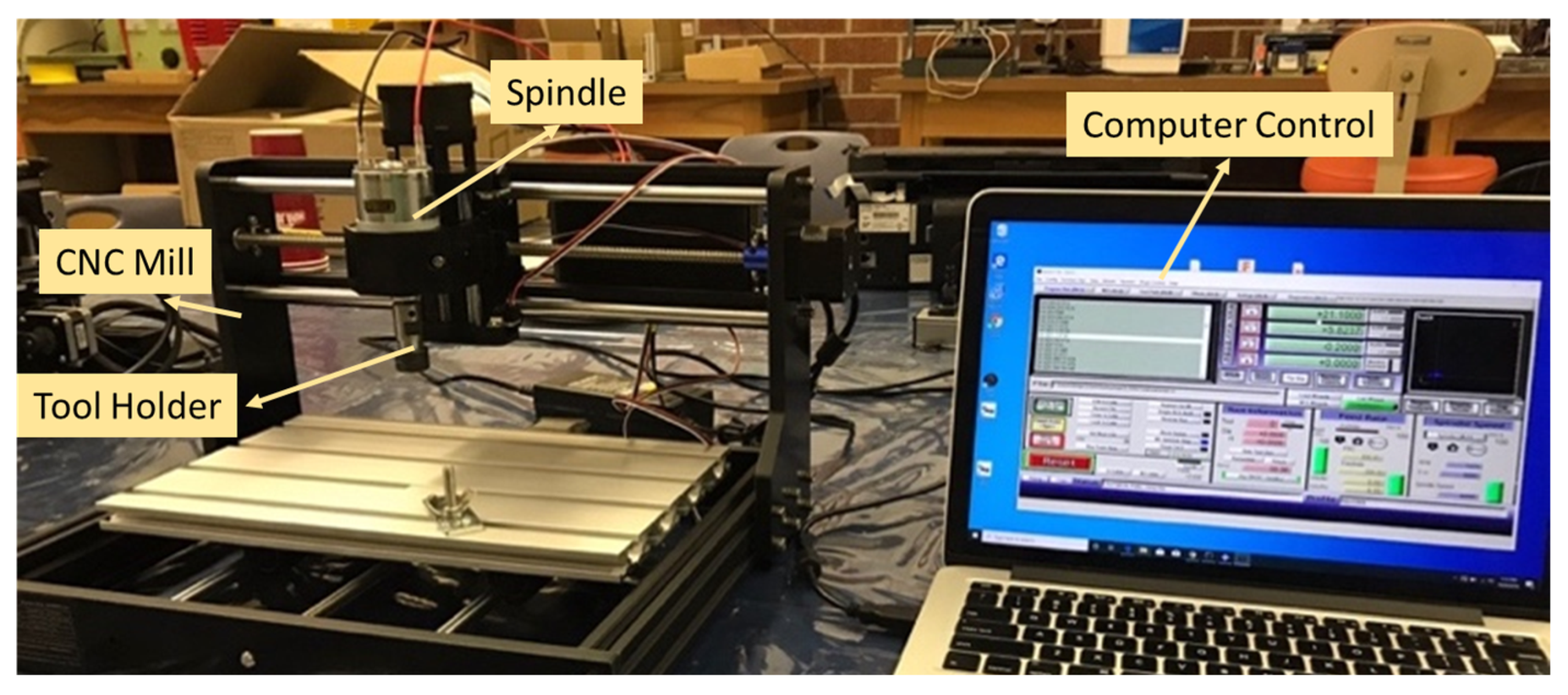
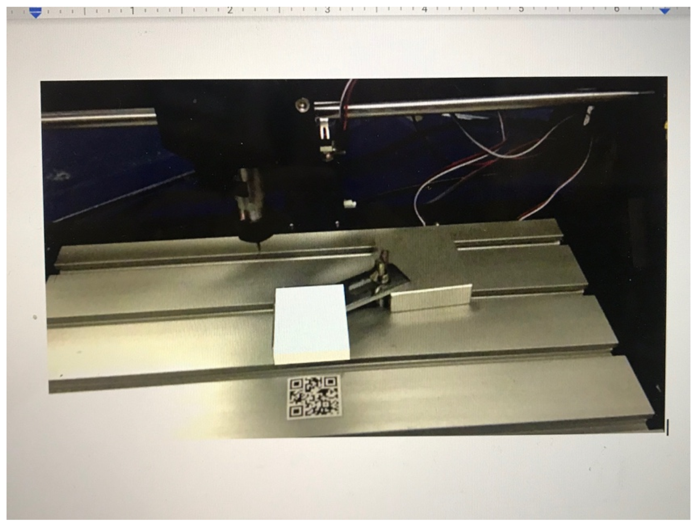
2.1. Experimentation: Real-World CNC Machining

For the case discussed in this paper—a CNC Milling Process is analyzed. A CNC Mill is a cutting machine where the workpiece is stationary (mounted to the table), and the cutting tool spins at a set revolution per minute (rpm). The tool travels in 3 different axes (x, y, z) and traverses across the workpiece based on a feed rate (inches per minute). In an ideal case, when the tool is engaged in the material, two essential factors determine the size of the cut: axial depth of cut and radial depth of cut. An example where an endmill is contouring the side edge of a workpiece—the axial depth of cut (d.o.c.) represents how deep the tool is engaged in the material (typically in relation to the z-axis), and the radial d.o.c. also known as step-over represents how much of the diameter of the tool is engaged in the material (in the x-axis and/or y-axis).
In a real-world case, several factors have significant effects on how accurate the cut is in relation to the program’s exact values. For example, a CNC Mill can be programmed to take a 0.020″ (or 0.508 mm) radial d.o.c. at a depth of 0.500″ (or 12.7 mm) (axial d.o.c.), and in the aforementioned ideal case above, this programmed tool path would produce a new feature in the workpiece with these exact dimensions. In reality, the dimension of the new feature can either be larger or smaller. Some significant challenges that cause this difference include tool deflection due to excessive tool pressure caused from taking too large of a cut; “rubbing” of the tool from poor cutting-edge engagement caused by too small of a cut, an incorrect spindle speed and/or feed rate; and variations in the properties of the material specifically it’s machinability rating which is based on factors including hardness and ultimate tensile strength (UTS). When parameters are incorrect, it translates to the workpiece in different forms, including surface roughness caused by vibration and, more prominently, excessive heat from either too much material being removed or material being removed too quickly. This excess heat can also cause a phenomenon known as work hardening, where the material gains hardness during the process making it more challenging to control size and surface smoothness on additional cuts.
The biggest challenge with the real-world case is how a technician working on the machine adjusts help produce the most accurate cut possible. These adjustments (i.e., reducing the feed rate or increasing the spindle speed) are made from extensive machining experience and knowledge. Additional benefits to a cutting process that produces accurate cuts are longer tool life, reduced wear on the machine, and safer working conditions for the operator. For the specific example in this paper, the focus is given on the average interaction temperature with moderate d.o.c., feed rate, and spindle speed (parameters determined from historical machining data and experimentation). With this in mind, assumption is made that the tool is rigid (minimal tool deflection). The workpiece set-up is robust. The workpiece material has ideal homogenous properties that can be resembled in engineering software.
The CNC Machine used for testing is a CNC Mill (Make: SainSmart, China), as seen below in Figure 1, which can be programmed to travel in the x, y, and z directions. The machine will be using a 0.125″ (or 3.175 mm) diameter 4-flute square-end carbide endmill with a length of cut of 0.500″ (or 12.7 mm) as it’s cutting tool and will machine into an AA6061-T6 Aluminum alloy workpiece mounted on the table. The initial size of the workpiece is a 2″ × 2″ × 2″ block. The initial operating parameters for the tool are 1200 rpm, a feed rate of 5 ipm, a radial d.o.c. of 0.025″ (or 0.635 mm) and an axial d.o.c. of 0.500″ (or 12.7 mm). In relation to the tool dimensions, the radial d.o.c. is a 20% stepover and the axial d.o.c. is 100% of the length of cut available.
The first step of the testing process is to do some initial cuts using the parameters above and determine how accurate the initial cutting process is. Multiple cuts are taken with the 0.025″ step over, and after each cut—a micrometer measuring tool is used to measure the width of the block, allowing us to determine how much material is removed. The settled upon feed rate (5 ipm or 127 mm per minute) and rpm (1200) gave us material removal accuracy to the 0.001″. The tool engaged the material for a length of 1″ and this is repeated 3 times over with temperatures taken after each pass using an Infrared (IR) temperature gun. The average initial temperature of the workpiece material before the first cut is 18.055 °C. The IR thermometer used is an EXTECH Model 42510A (Make: Extech Instruments, Nashua, NH, USA) with a temperature range of −50 °C to 650 °C.

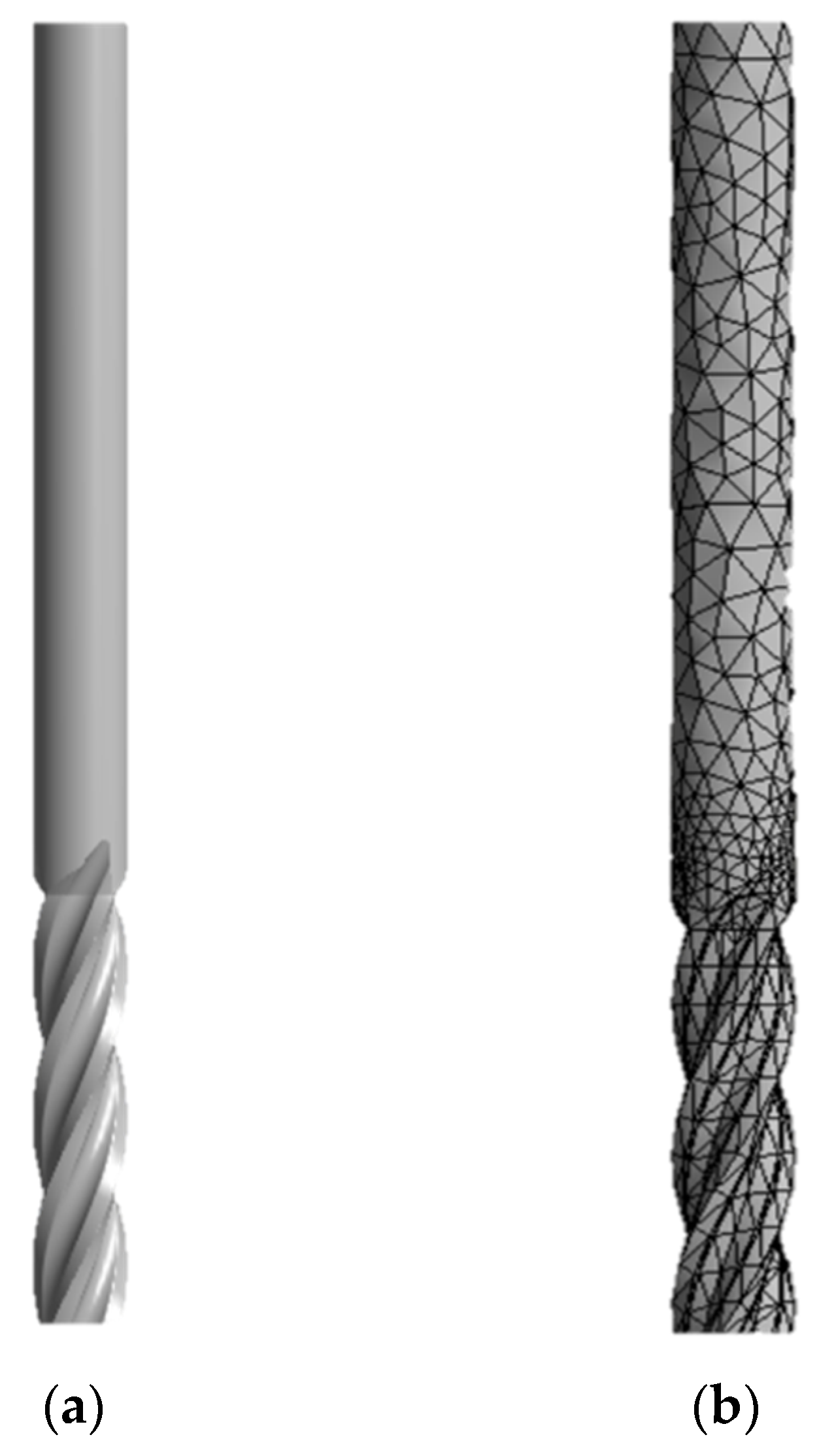
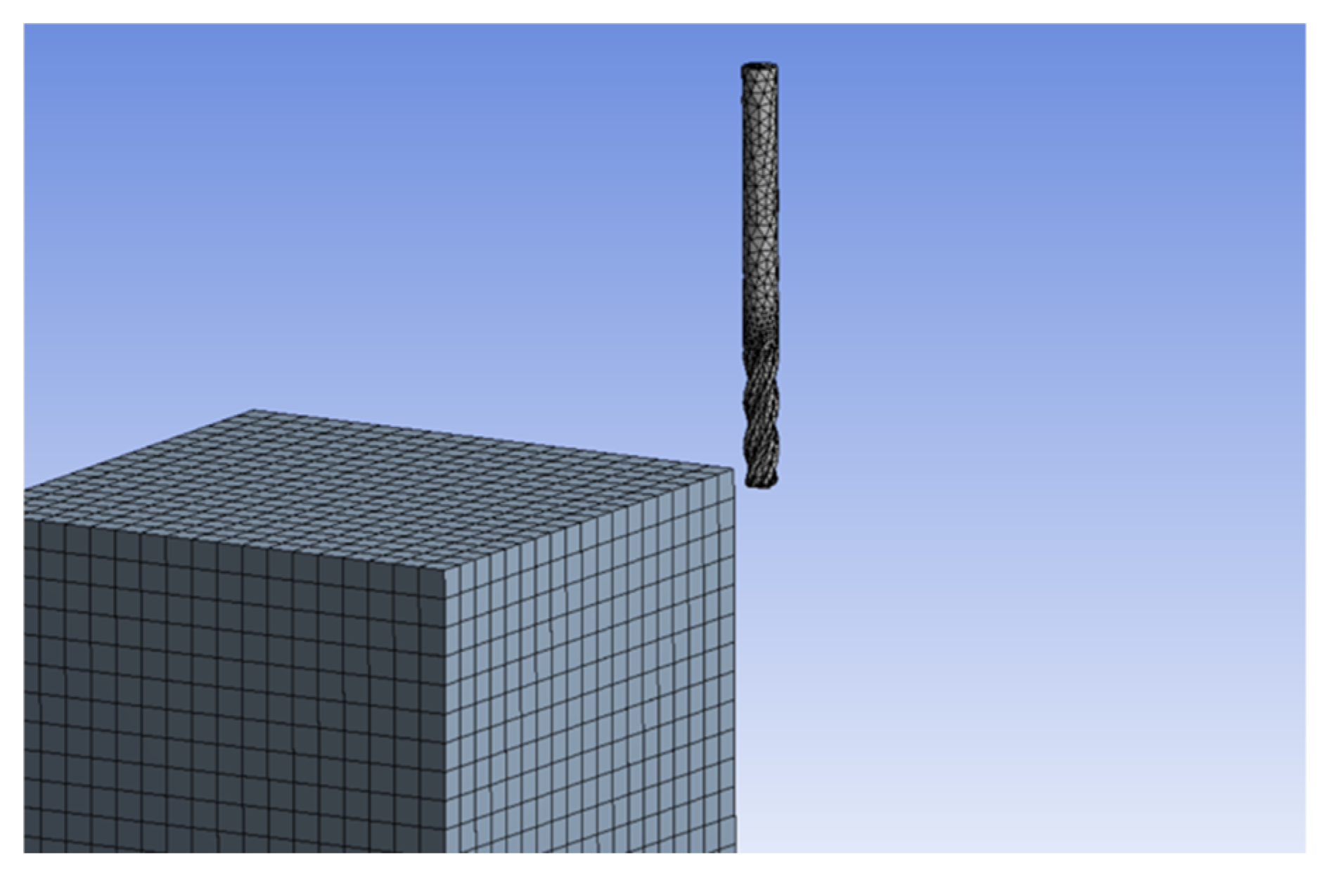
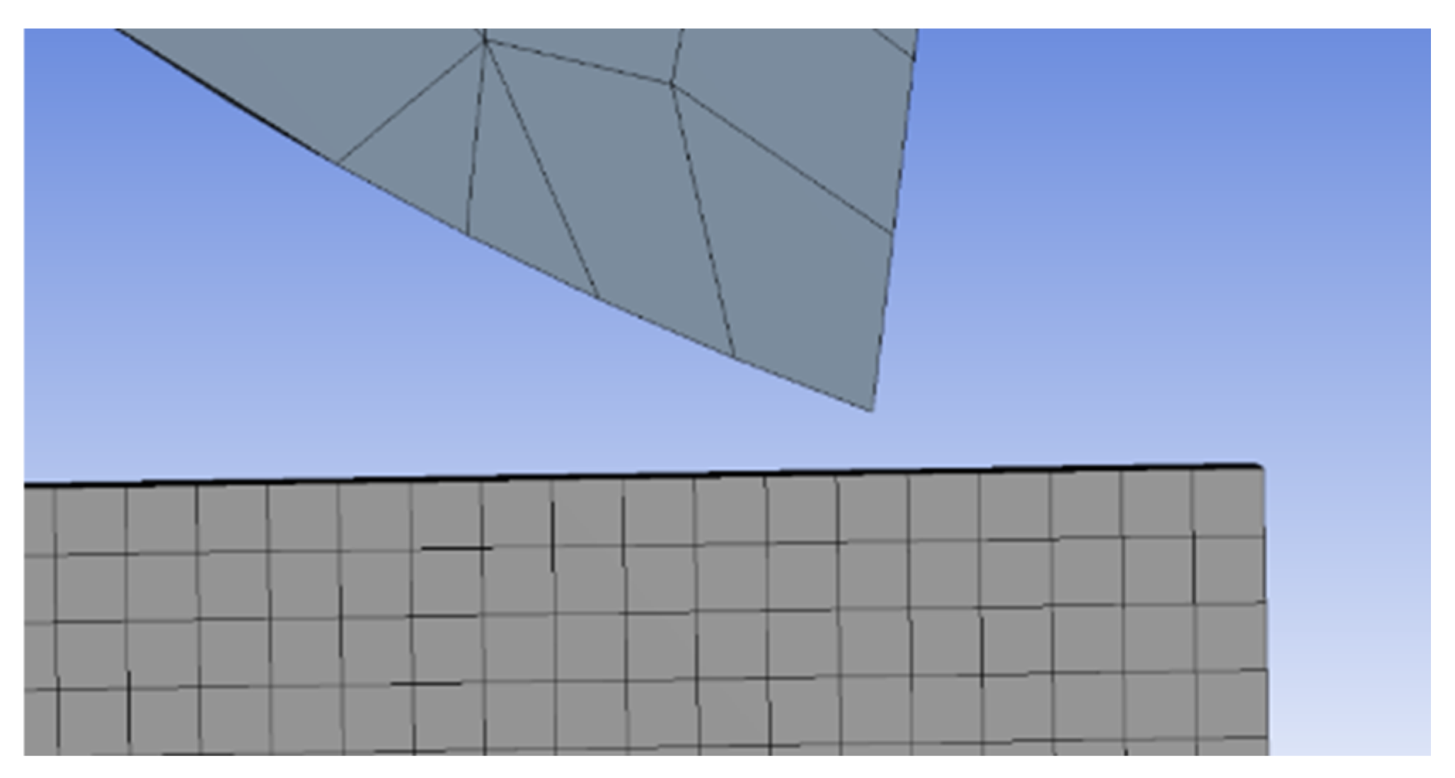
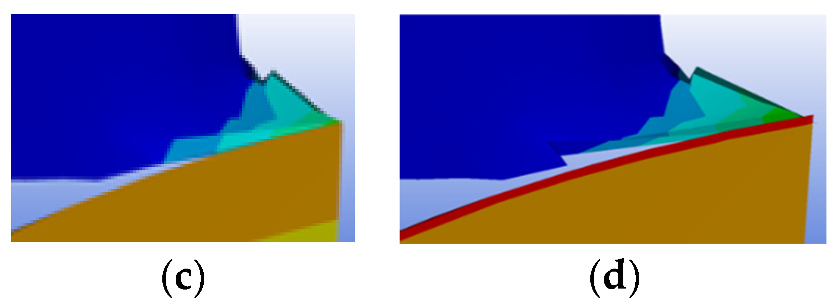
2.2. Finite Element Analysis and Simulation

The next step of the process is to input these parameters (tool size and geometry, workpiece and tool material, cutting parameters) into the FEA software (Version: ANSYS 2020, Ansys, Inc., Canonsburg, PA, USA)and run a cutting simulation. This simulation can show the cutting interaction average temperature, which, as discussed above, is a leading indicator for the quality of the cut. The simulation can predict how the chip formation will occur, resulting in a real-life material removal rate (MRR). This information can help determine if the original cutting parameters used are optimal. For example, if the feed rate is too high or the d.o.c. is too large, the software will show extremely high temperatures, poor chip formation, and varying size measurements across the length of the cut. This high-temperature condition on the actual machine could result in the tool breaking, extreme “chatter” in the cut due to non-smooth cutting action, and even the workpiece moving on the machine. The explicit dynamics simulation representing a steel cutting tool engaging in an aluminum alloy workpiece (same interaction as above) is completed using ANSYS 2020. For the simulation, the material specifications are loaded for steel and AA6061-T6 aluminum alloy. The coefficient of static friction is set at 0.61, and the dynamic coefficient is set at 0.42, which represents the relationship between aluminum alloy and steel and is used as a body interaction in the simulation. For the boundary conditions of the model, the velocity (in positive X) is set to 5 ipm (or 127 mm per minute), and angular velocity (around Y) is set to 1200 rpm. A Hex Dominant Method Mesh pattern (mixed element type, predominantly hexahedral elements), as seen below in Figure 2, is used, setting the mesh of the tool body (rigid) at 0.025″ and the mesh of the workpiece (flexible) is set at 0.004″ (or 0.1016 mm). The mesh sizes are determined based on a mesh-sensitivity analysis. The workpiece mesh considered here consists of 15,625 nodes.
The simulation’s end time is set to 4.1 × 10⁻⁴ s, which gives enough time for the cutting edge on the tool to engage and remove material associated with the one cut fully. For this experiment, the first tool engagement average temperature is correlated directly to the temperature taken at the cutting interaction with the IR temperature gun on the “real” workpiece. The minimum step time is set to 5 × 10⁻⁹ s. There is fixed support set up on the bottom face of the workpiece representing the clamping force of the “real” material being held on the machine. The set-up of the tool to the workpiece is shown below in Figure 3, along with the Initial Cutting Engagement shown above in Figure 4. Table 1 shows the key parameters used in this study.

3. Results and Discussion

3.1. Integration of Real-World Machining and FEA Simulation

For the simulation, the initial environmental temperature is set at 18.055 °C (same as the actual cutting parameters). It then is adjusted for each trial with the final average temperature of the previous simulation trial (representing how the piece gets hotter after every cut). Figure 5 below shows a time-lapse of the first cutting tool engagement to the workpiece. The first image shows the cutting engagement at 1.025 × 10⁻⁴ s, the second image shows the cutting engagement at 2.05 × 10⁻⁴ s, the third image shows the cutting engagement at 3.075 × 10⁻⁴ s, and the fourth image shows the cutting engagement at 4.1 × 10⁻⁴ s. In Figure 5 below, the blue represents the ambient temperature of 18.055 °C and the color gets lighter as the temperature rises culminating in the red color at the cutting edge representing the high temperatures of the tool engagement.
The temperature data from the real cutting is recorded. This data is compared to similar data created from the FEA simulation. This correlation can be analyzed to determine if any additional factors are causing a disconnect and how accurate the software is in relation to the application. Based on basic machining principles, excessive temperatures are related to poor cutting quality and reduced dimensional accuracy. Therefore, a guide could be created to help an inexperienced operator make adjustments based on visual indicators from the real-time FEA.
These findings would help manufacturing industries utilize a highly accurate FEA simulation and superimpose it into real-time MR environments. It allows adjustments to be made to cutting parameters based on basic visual indicators instead of more difficult indicators requiring extensive experience to recognize. This simulation and actual cut resulted in the following data shown below in Table 2.
Overall, there is a clear correlation between the temperature of the “real” part being machined and the temperature shown during the simulation with similar parameters shown below in Figure 6. Looking at the graphs in Figure 6, there is an initial offset of temperatures between the simulation and real-cut shown on the second temperature taken, which then follows a trend line correlating the data. This initial grid shift can be explained through a rise in temperature occurring when the first cutting edge engages the material, and this is challenging for the software to accurately determine this point of engagement. Although the trend lines of the data are offset, the similar temperature changes prove that the data from the simulation and the cut can be adjusted and used to accurately predict a real cutting situation. There is a correlation between the temperature-induced in the part and how accurate the cut is from determining the initial parameters. The technology is available today to accurately provide the FEA simulation and utilize it in a mixed reality environment. This combination of technologies has been seen in education, training, and force values for equipment usage, such as the force put into a ladder step—but has not specifically been combined in a CNC machining application. Additional simulation parameters can be easily added to this (measuring stress-induced in part by the cutting tool, the vibration of workpiece and tool in cut, sound measurements), all of which can reinforce the real-time mixed reality environment giving the machine operator even more information to help troubleshoot a poor cutting scenario.

3.2. Integrated Mixed-Reality Based Visualization Platform

After the simulations run, the future goal is to superimpose this simulation onto the real-life workpiece creating an MR environment. Unity 3D software is used to place a solid model block onto the workpiece block. Next, the simulation, which can be considered a compilation of still images, is superimposed on the machine while it is in its cutting motion. At this step, the FEA simulation is related in real-time to the actual cutting interaction showing exactly the temperatures the cutting tool is adding to the workpiece. This system will significantly reduce the operator’s experience to make changes to improve part quality. Below in Figure 7, a 3D model representation is shown of the workpiece and the cutting tool. This workpiece is loaded into Unity 3D, where it is superimposed on the real workpiece creating at Mixed-Reality environment shown below in Figure 8.
This combination of technology can also be used on other manufacturing processes, from 3D printing to welding, to help inexperienced technicians with the tools to show exactly what is happening to the workpiece in real-time and help guide them to make decisions that will improve the quality of the operation at hand. Additional MR based research can be expanded into different FEA studies, including yield stress, tensile stress, vibration to help predict surface finish and fluid flow to determine the benefits of using cutting fluids. The research can also be expanded into other manufacturing processes, including drilling, turning, saw cutting, and 5-axis profile milling. The future work for this project will include more experimentation with parameter changes including workpiece material, cutting size and material, and cutting parameters. With additional data taken, the simulation can be fine-tuned to improve results and give accurate data quickly. This technology can be implemented in real-life manufacturing environments helping industries including medical devices, aerospace and automotive industries.

4. Conclusions

In this study, the use of real-time Finite Element Analysis (FEA) in an MR environment is demonstrated for CNC machining applications. The following conclusions are drawn:
  • FEA can be simulated in a way that is efficient and quick, giving similar results to an actual machining process.
  • Real-Time FEA in an MR environment can be a useful tool in helping improve a CNC machining process.
  • The study also determined that FEA and MR technologies can be integrated to benefit various manufacturing processes and applications.
The outcome of this research would pave the way for future manufacturing operations to be economically competitive with higher efficiencies and improved sustainability. The applications of this research may be limited by the extensive computational requirements for mixed reality technologies.

Author Contributions

S.J. conceived the idea for research. S.J. and G.E. designed the methodology and experimental setup and outlined the paper. G.E. conducted the literature review, performed experiments, and collected data. S.J. and G.E. analyzed the data and wrote the manuscript’s results. All authors have read and agreed to the published version of the manuscript.

Funding

This research received no external funding.

Data Availability Statement

Not applicable.

Acknowledgments

The College of Engineering and Computer Science (ECS) facilities at California State University Fullerton are acknowledged.

Conflicts of Interest

The authors declare no conflict of interest.

References

  1. Mourtzis, D.; Zogopoulos, V.; Katagis, I.; Lagios, P. Augmented Reality based Visualization of CAM Instructions towards Industry 4.0 paradigm: A CNC Bending Machine case study. Procedia CIRP 2018, 70, 368–373. [Google Scholar] [CrossRef]
  2. Bagheri, B.; Yang, S.; Kao, H.-A.; Lee, J. Cyber-physical systems architecture for self-aware machines in industry 4.0 environment. IFAC-Pap. 2015, 48, 1622–1627. [Google Scholar] [CrossRef]
  3. Cui, Y.; Kara, S.; Chan, K.C. Manufacturing big data ecosystem: A systematic literature review. Robot. Comput.-Integr. Manuf. 2020, 62, 101861. [Google Scholar] [CrossRef]
  4. Auschitzky, E.; Hammer, M.; Rajagopaul, A. How Big Data Can Improve Manufacturing. 2014. Available online: https://www.mckinsey.com/capabilities/operations/our-insights/how-big-data-can-improve-manufacturing (accessed on 20 January 2023).
  5. Hu, S.J. Evolving paradigms of manufacturing: From mass production to mass customization and personalization. Procedia Cirp 2013, 7, 3–8. [Google Scholar] [CrossRef] [Green Version]
  6. Tien, J.M. Manufacturing and services: From mass production to mass customization. J. Syst. Sci. Syst. Eng. 2011, 20, 129–154. [Google Scholar] [CrossRef]
  7. Orji, I.J. Examining barriers to organizational change for sustainability and drivers of sustainable performance in the metal manufacturing industry. Resour. Conserv. Recycl. 2019, 140, 102–114. [Google Scholar] [CrossRef]
  8. Niaki, M.K.; Torabi, S.A.; Nonino, F. Why manufacturers adopt additive manufacturing technologies: The role of sustainability. J. Clean. Prod. 2019, 222, 381–392. [Google Scholar] [CrossRef]
  9. Jaegers, T.; Lipp-Lingua, C.; Amil, D. High-technology and medium-high technology industries main drivers of EU-27’s industrial growth. Stat. Focus 2013, 1. [Google Scholar]
  10. Valentino, J.; Goldenberg, J. Introduction to Computer Numerical Control (CNC); Prentice Hall: Englewood Cliffs, NJ, USA, 2003. [Google Scholar]
  11. Yang, D.C.; Kong, T. Parametric interpolator versus linear interpolator for precision CNC machining. Comput.-Aided Des. 1994, 26, 225–234. [Google Scholar] [CrossRef]
  12. Lasemi, A.; Xue, D.; Gu, P. Recent development in CNC machining of freeform surfaces: A state-of-the-art review. Comput.-Aided Des. 2010, 42, 641–654. [Google Scholar] [CrossRef]
  13. Kara, F.; Aslantaş, K.; Cicek, A. Prediction of cutting temperature in orthogonal machining of AISI 316L using artificial neural network. Appl. Soft Comput. 2016, 38, 64–74. [Google Scholar] [CrossRef]
  14. Markopoulos, A.P. Finite Element Method in Machining Processes; Springer Science & Business Media: Berlin/Heidelberg, Germany, 2012. [Google Scholar] [CrossRef]
  15. Jin, X.; Altintas, Y. Prediction of micro-milling forces with finite element method. J. Mater. Process. Technol. 2012, 212, 542–552. [Google Scholar] [CrossRef]
  16. Ribeiro, J.P.; Tavares, S.M.; Parente, M. Stress–strain evaluation of structural parts using artificial neural networks. Proc. Inst. Mech. Eng. Part L J. Mater. Des. Appl. 2021, 235, 1271–1286. [Google Scholar] [CrossRef]
  17. Özel, T.; Ulutan, D. Prediction of machining induced residual stresses in turning of titanium and nickel based alloys with experiments and finite element simulations. CIRP Ann. 2012, 61, 547–550. [Google Scholar] [CrossRef]
  18. Joldes, G.R.; Wittek, A.; Miller, K. Real-time nonlinear finite element computations on GPU–Application to neurosurgical simulation. Comput. Methods Appl. Mech. Eng. 2010, 199, 3305–3314. [Google Scholar] [CrossRef] [PubMed] [Green Version]
  19. Berkley, J.; Turkiyyah, G.; Berg, D.; Ganter, M.; Weghorst, S. Real-time finite element modeling for surgery simulation: An application to virtual suturing. IEEE Trans. Vis. Comput. Graph. 2004, 10, 314–325. [Google Scholar] [CrossRef]
  20. Linder-Ganz, E.; Yarnitzky, G.; Yizhar, Z.; Siev-Ner, I.; Gefen, A. Real-time finite element monitoring of sub-dermal tissue stresses in individuals with spinal cord injury: Toward prevention of pressure ulcers. Ann. Biomed. Eng. 2009, 37, 387. [Google Scholar] [CrossRef]
  21. Phellan, R.; Hachem, B.; Clin, J.; Mac-Thiong, J.M.; Duong, L. Real-time biomechanics using the finite element method and machine learning: Review and perspective. Med. Phys. 2021, 48, 7–18. [Google Scholar] [CrossRef]
  22. Duriez, C. Control of elastic soft robots based on real-time finite element method. In Proceedings of the 2013 IEEE International Conference on Robotics and Automation, Karlsruhe, Germany, 6–10 May 2013; pp. 3982–3987. [Google Scholar]
  23. Huang, J.; Ong, S.-K.; Nee, A.Y. Real-time finite element structural analysis in augmented reality. Adv. Eng. Softw. 2015, 87, 43–56. [Google Scholar] [CrossRef]
  24. Huang, J.; Ong, S.-K.; Nee, A.Y. Visualization and interaction of finite element analysis in augmented reality. Comput.-Aided Des. 2017, 84, 1–14. [Google Scholar] [CrossRef]
  25. Speicher, M.; Hall, B.D.; Nebeling, M. What is mixed reality? In Proceedings of the 2019 CHI Conference on Human Factors in Computing Systems, Glasgow, UK, 4–9 May 2019; pp. 1–15. [Google Scholar]
  26. Chen, L.; Day, T.W.; Tang, W.; John, N.W. Recent developments and future challenges in medical mixed reality. In Proceedings of the 2017 IEEE International Symposium on Mixed and Augmented Reality (ISMAR), Nantes, France, 9–13 October 2017; pp. 123–135. [Google Scholar]
  27. Gonzalez-Franco, M.; Pizarro, R.; Cermeron, J.; Li, K.; Thorn, J.; Hutabarat, W.; Tiwari, A.; Bermell-Garcia, P. Immersive mixed reality for manufacturing training. Front. Robot. AI 2017, 4, 3. [Google Scholar] [CrossRef] [Green Version]
  28. Watanuki, K. A mixed reality-based emotional interactions and communications for manufacturing skills training. In Emotional Engineering; Springer: Berlin/Heidelberg, Germany, 2011; pp. 39–61. [Google Scholar]
  29. Lee, J.; Han, S.; Yang, J. Construction of a computer-simulated mixed reality environment for virtual factory layout planning. Comput. Ind. 2011, 62, 86–98. [Google Scholar] [CrossRef]
  30. Liverani, A.; Amati, G.; Caligiana, G. Interactive control of manufacturing assemblies with Mixed Reality. Integr. Comput. -Aided Eng. 2006, 13, 163–172. [Google Scholar] [CrossRef]
  31. Lee, J.-M.; Lee, K.-H.; Kim, D.-S.; Kim, C.-H. Active insp ection supporting system based on mixed reality after design and manufacture in an offshore structure. J. Mech. Sci. Technol. 2010, 24, 197–202. [Google Scholar] [CrossRef]
  32. Munoz, A.; Mahiques, X.; Solanes, J.E.; Marti, A.; Gracia, L.; Tornero, J. Mixed reality-based user interface for quality control inspection of car body surfaces. J. Manuf. Syst. 2019, 53, 75–92. [Google Scholar] [CrossRef]
Figure 1. CNC Mill—cutting parameters controlled through computer inputs.
Metals 13 00286 g001
Figure 2. (a) CAD model of the 4 flute endmill and (b) Model with mesh geometry.
Metals 13 00286 g002
Figure 3. Cutting Tool with Workpiece—tool before contour engagement.
Metals 13 00286 g003
Figure 4. Initial Cutting Engagement—first engagement of cutting tool on the workpiece.
Metals 13 00286 g004
Figure 5. Cutting Tool Engagement over 4 discrete time periods—(a) at 1.025 × 10⁻⁴, (b) 2.05 × 10⁻⁴, (c) 3.075 × 10⁻⁴, and (d) 4.1 × 10⁻⁴.
Metals 13 00286 g005aMetals 13 00286 g005b
Figure 6. Comparison of real-world experimentation and FEA simulation data.
Metals 13 00286 g006
Figure 7. Computer Model Simulation—Virtual Reality.
Metals 13 00286 g007
Figure 8. Image of Mixed Reality Block—representing the block model superimposed over the real-world workpiece.
Metals 13 00286 g008
Table 1. Simulation Parameters used in this study.
Time step5 × 10−9 s
Ambient temperature18.055 °C
Tool bodyRigid, mesh size 0.025″
Workpiece bodyFlexible, mesh size 0.004″
Table 2. Real Workpiece vs. Simulation Data.
ConditionRealSimulation
Ambient, °C18.05518.055
Pass 1, °C23.55619.124
Pass 2, °C24.27820.193
Pass 3, °C26.27821.262
Disclaimer/Publisher’s Note: The statements, opinions and data contained in all publications are solely those of the individual author(s) and contributor(s) and not of MDPI and/or the editor(s). MDPI and/or the editor(s) disclaim responsibility for any injury to people or property resulting from any ideas, methods, instructions or products referred to in the content.

