Abstract
Carbon nanoparticles have excellent lubricating properties, however, they are less involved in metal protection. In this study, easily prepared candle soot was added to electroless nickel-phosphorus plating as a re-enforcement particle. Ball-disc friction and wear tests were conducted to evaluate the wear-resistance capabilities of the electroless Ni-P coating and Ni-P-CS (Candle Soot) composite coatings. The parameters for the friction coefficient, wear amount, and friction morphology of the Ni-P-CS composite coatings were studied after being heat-treated (300 °C, 400 °C, 500 °C, and 600 °C). The surface morphology and phase composition of the Ni-P-CS composite coatings after thermal treatment at various temperatures were also investigated. The results are as follows: heat treatment strengthens the local hardness of the Ni-P-CS composite coating but does not further enhance wear resistance. Compared with the Ni-P coating and the heat-treated Ni-P-CS composite coating, the Ni-P-CS composite coatings without heat treatment have a lower friction coefficient (0.35) and better wear resistance.
1. Introduction
Electroless plating is a process of reducing metal ions in the plating solution with an oxidation of the reducing agent without electric plating. Composite particles are deposited on a metal surface with reduced metal ions simultaneously in a plating solution in order to form a composite coating. In 1844, Wurtz first detected that nickel atoms could be deposited in an aqueous solution in the presence of ions. Since then, chemical nickel-phosphorus plating and chemical composite plating have been extensively explored by researchers [1]. Over the past few decades, researchers have conducted countless studies on chemical composite plating. Now, the research focus has shifted to the performance and application of chemical composite coatings. In former investigations, there were numerous composite coatings with excellent wear resistance and corrosion resistance [2], i.e., Ni-P-PTFE, Ni-P-SiO2-Al2O3, Ni-P-Co, CeO2, and Ni-P/Ni-B-B4C have noticeably enhanced the wear resistance or mechanical properties of nickel-phosphorus-based chemical coatings [3,4,5,6]. Tamilarassan et al. [7] explored the wear and scratch behaviors of the chemical Ni-P/TiO2 and experimentally confirmed that the optimal concentration of surfactant could produce a coating with extreme wear resistance and a low friction coefficient. There also exists much research on self-lubricating coatings; these are composite coatings that exhibit an anti-wear effect. The added composite particles are commonly called ‘solid lubricating particles’ and exhibit a self-lubrication effect [8], examples include MoS2, BN, graphite, and polytetrafluoroethylene (PTFE). When these particles are uniformly distributed within the matrix coating, they act as lubricants and wear-reducing agents during surface friction and present excellent wear resistance. Ni-P-based self-lubricating composite coatings are exploited in precision instrument fittings, automobile clutch parts, plastic and plastic moldings, bearings, gears, nuts and bolts, and more. However, the solid lubricating particles incorporated in previous explorations are difficult to utilize in a broad range of applications due to their small size, cost, and because they are difficult to prepare, thereby, few investigations have been devoted to the combination of carbon nanoparticles and electroless plating.
In this study, we have successfully prepared a wear-resistant Ni-P-CS composite coating on a low-carbon steel substrate by adding candle soot enriched with carbon nanoparticles. The wear resistance of the composite coating was evaluated by friction and wear tests, and the effect of heat treatment on the performance of the composite coating is discussed. The friction mechanism of the wear-resistant coating is also discussed in some detail. The Ni-P-CS composite coating shows promise as a low-cost, easy-to-prepare wear-resistant coating that can be employed in numerous applications in aerospace, automotive, electronics, petroleum, chemical, metallurgy, and nuclear energy.
2. Materials and Methods
2.1. Coatings Preparation
Preparation of Ni-P-CS composite coatings. Step 1: A total of 1 L of deionized water was added into a beaker. Then, 0.1 mg sodium dodecyl sulfonate and candle soot (0.75 g) were added into the deionized water and heated to 60 °C while stirring. Step 2: Nickel sulfate hexahydrate (20 g), sodium hypophosphite (24 g), citric acid (16 g), and sodium succinate (6 g) were added into the solution in step 1 and stirred for 5 min. Step 3: The mixture from step 2 was placed in an ultrasonic cleaning machine for 10 min to obtain a compound chemical bath solution. The Ni-P coating was also prepared in the same procedure only without candle soot added. The thickness of the coating was controlled by the plating time. In this work, the plating time was 2 h.
The substrate material for chemical deposition was common grade Q235B low-carbon steel, a kind of mild steel. Due to its low strength, hardness, and softness, Q235B steel is low-cost and extensively utilized, so its surface modifications have more economic value. The chemical compositions of low-carbon steel are provided in Table 1. All the substrate steel was cut into a sample size of 10 mm × 3 mm by using a wire-cutting machine. The low-carbon steel samples were then polished with SiC sandpaper with meshes of 100#, 320#, 400#, 500#, 800#, 1000#, and 1200# in sequence to obtain a smooth surface. The samples were then activated in a 10% HCl solution for about 1 min and washed with deionized water. After washing, the sample was placed in the bath solution at 85 °C for 2 h.

Table 1.
Composition of Q235B low-carbon steel.
2.2. Wear Test and Characterization
The wear resistance of Ni-P-CS coating was tested by a WTM-2E sphere-disc friction wear test machine with a friction ball radius of 2 mm. The load magnitude was 10 N and the friction time was 30 min. The counter-body grinding material was a GCr15 sphere and the friction condition was dry grinding. Microscopic hardness was measured by employing the HVS-1000 micro Vickers hardness tester (made by shjingmi, Shanghai, China) with a load of 0.45 N, and the average of five measurement results was taken as the measured value. An SEM (Scanning Electron Microscope) (SIGMA 500, made by Carl Zeiss, Jena, Germany) was utilized for microscopic characterization and structural analysis. The XRD test was conducted by Shimadzu X-Ray powder Diffraction (XRD-6000, made by Shimadzu, Kyoto, Japan) with Cu-target and 3 KW of maximum power. The scanning range of the angle was 10°–80°, the step size was 0.02°, and the step number was 4. The KSL-1700X Muffle furnace (made by Kejing Group, Hefei, China) was also used for the heating treatment which lasted 1 h.
3. Results and Discussion
3.1. Characterization of Ni-P-CS Coatings
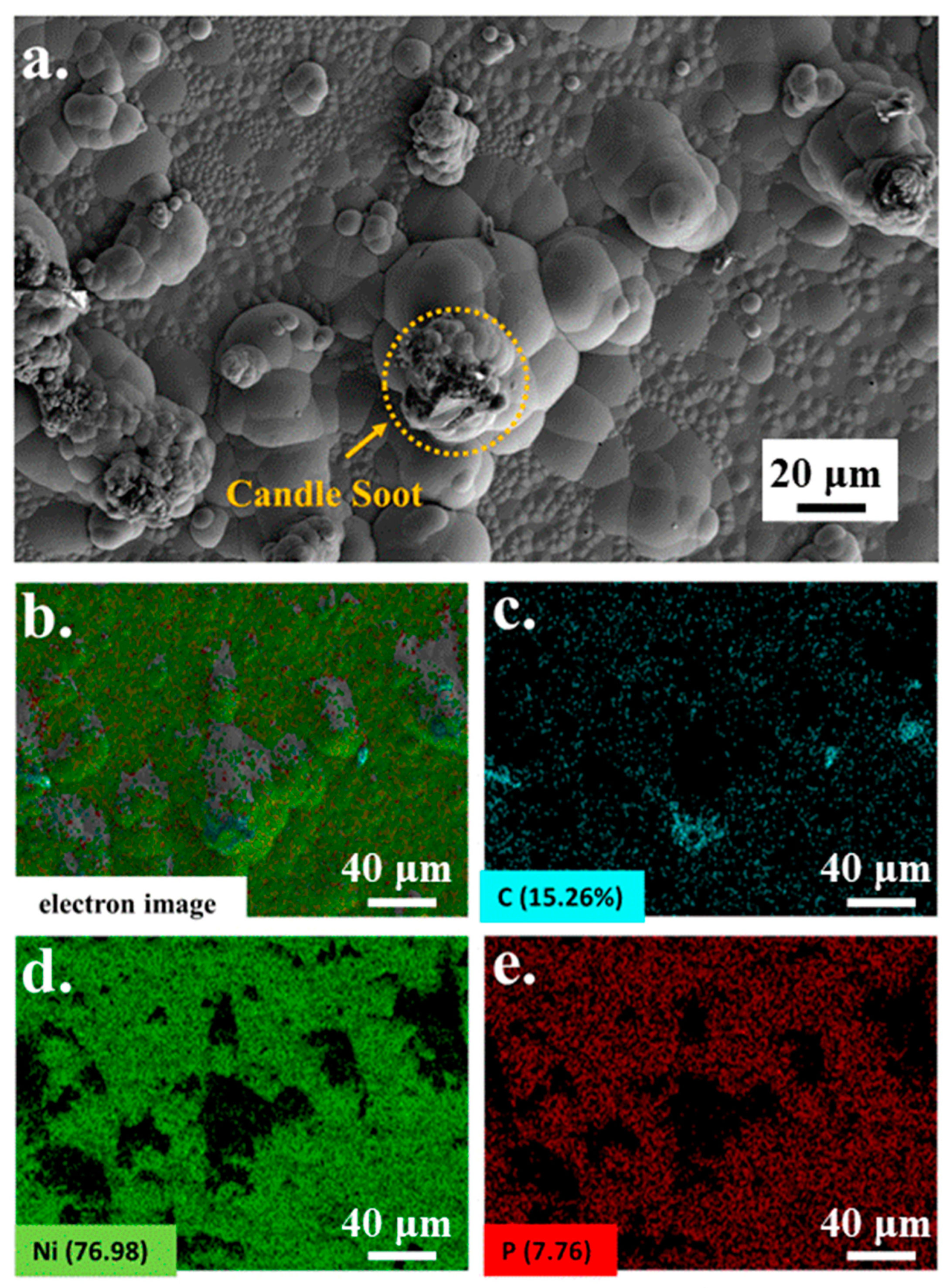
A microscopic image of candle soot is presented in Figure 1. Candle soot is a spherical carbon nanoparticle with an average size of 41.77 nm, calculated by the software of NanoMeasurer. Chemical nickel-phosphorus coatings are amorphous coatings with a cellular structure. The SEM and EDS were implemented to analyze the coating surfaces and to obtain electron images to observe their particular morphologies (see Figure 2). As demonstrated in the picture, the carbon nanoparticles appear as aggregates. According to the electron image (see Figure 2c), other reinforced carbon elements were uniformly distributed over the coating surface.
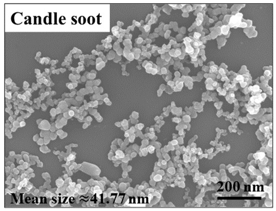
Figure 1.
SEM of candle soot.
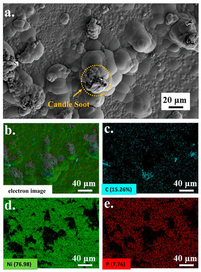
Figure 2.
SEM (a) of Ni-P-CS and EDS (b–e) element content of Ni-P-CS.
From Figure 2, we can see that Ni and P are evenly distributed throughout the coating, while element C is partly concentrated upon the hump of the coating. The other element C is uniformly distributed over the test surface as seen in Figure 2c. The amount of C is less than Ni and P. From Figure 2a, we found that some candle soot is still agglomerated on the hump of the coating.
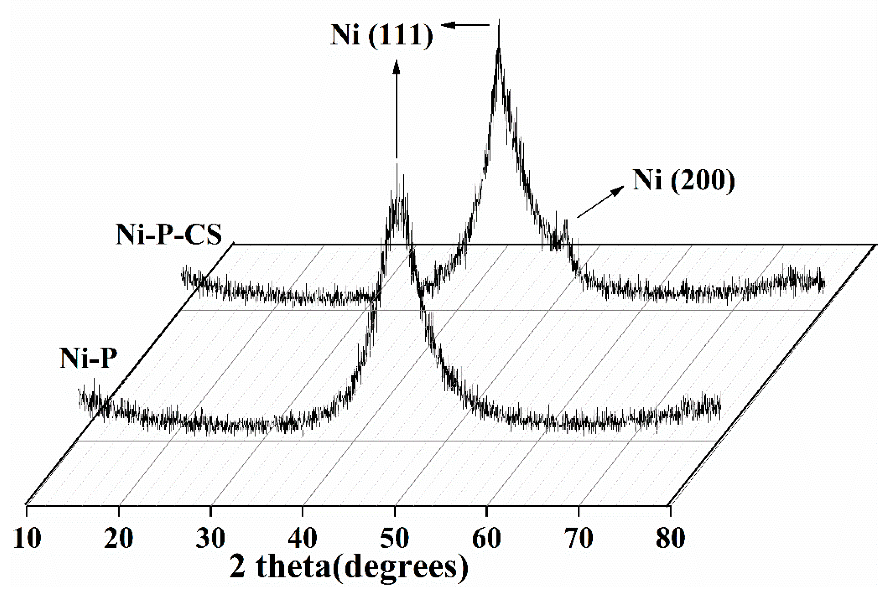
X-ray diffraction profiles were employed to examine the effect of the candle soot on the coating structure (see Figure 3). The picture reveals that the coating exhibited an amorphous structure with or without the candle soot. The graph of the Ni-P-CS coating shows an additional Ni (200) absorption peak compared with the Ni-P coating with a Ni (111) peak. Theoretically, the disorder of the atomic arrangement manifests itself in the X-ray diffraction pattern as a wide-ranging peak [9]. During the chemical deposition process, phosphorus atoms are stochastically trapped on top of nickel atoms, and the deflection rate of these atoms mostly determines the crystallinity of the deposit. Out of these two atoms, phosphorus diffuses at a lower rate compared to nickel [10]. Therefore, the reduced rate of binding of nickel and phosphorus atoms after candle soot doping inevitably leads to the formation of an ordered Ni lattice, which is reflected in the XRD diagram by the narrowing of the diffraction peak of the composite coating and the presence of an additional dwarf peak in the Ni (200) crystal plane. This issue is consistent with that reported in ref. [11].
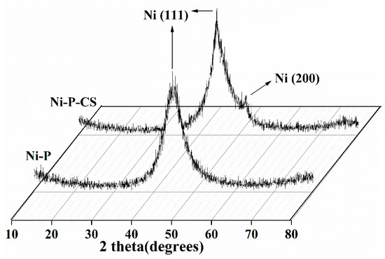
Figure 3.
XRD of the Ni-P and Ni-P-CS composite coatings.
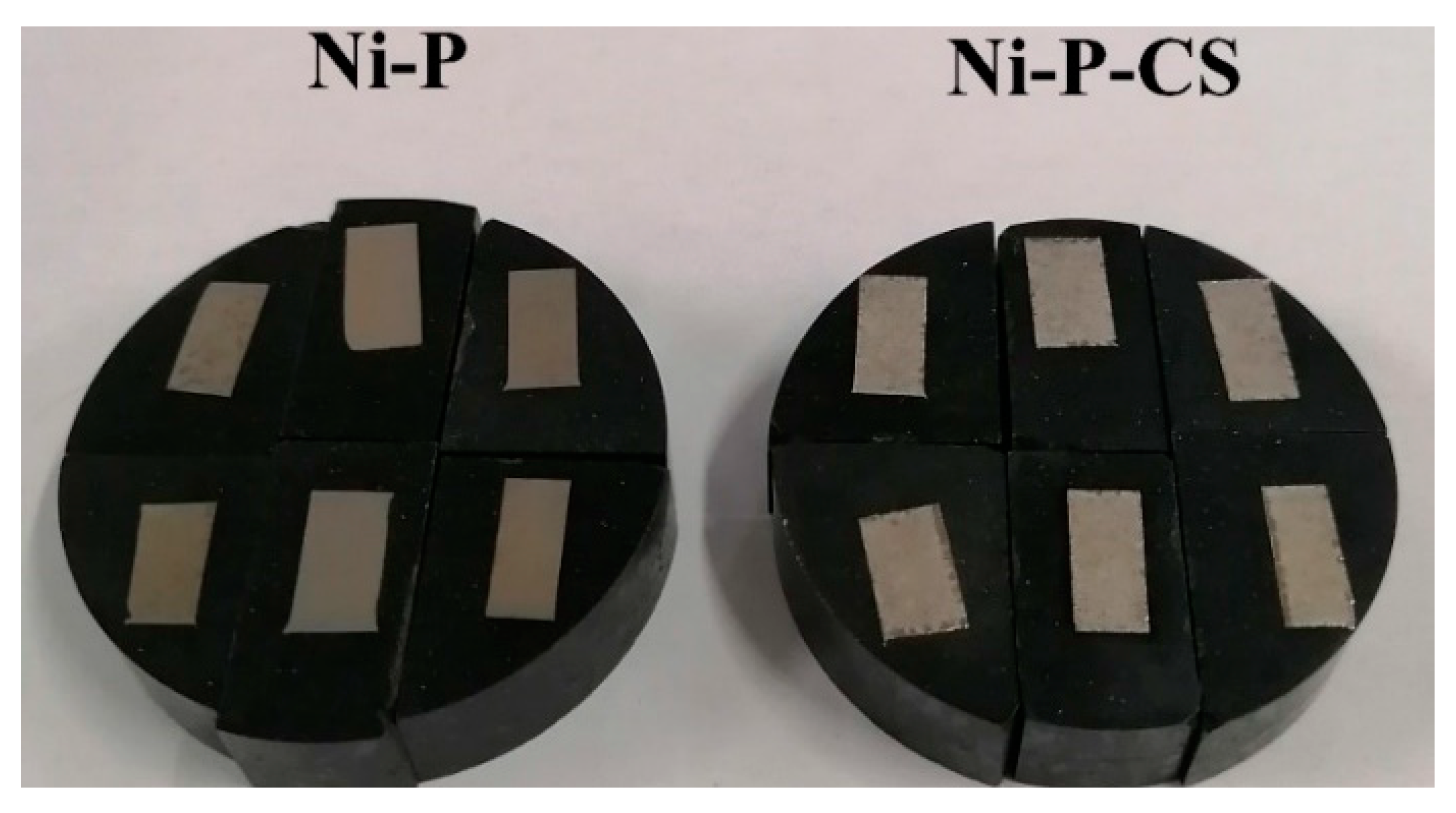
Physical images of Ni-P coatings and Ni-P-CS composite coatings are presented in Figure 4. There is a clear color difference between the two coatings, with the Ni-P coating showing a yellow metallic luster and the Ni-P-CS composite coating showing a silver metallic luster; both coatings have no apparent cracks or defects on the surface and are relatively flat.

Figure 4.
Ni-P coating and Ni-P-CS composite coatings.
3.2. The Effect of Heat Treatment on the Ni-P-CS Coating
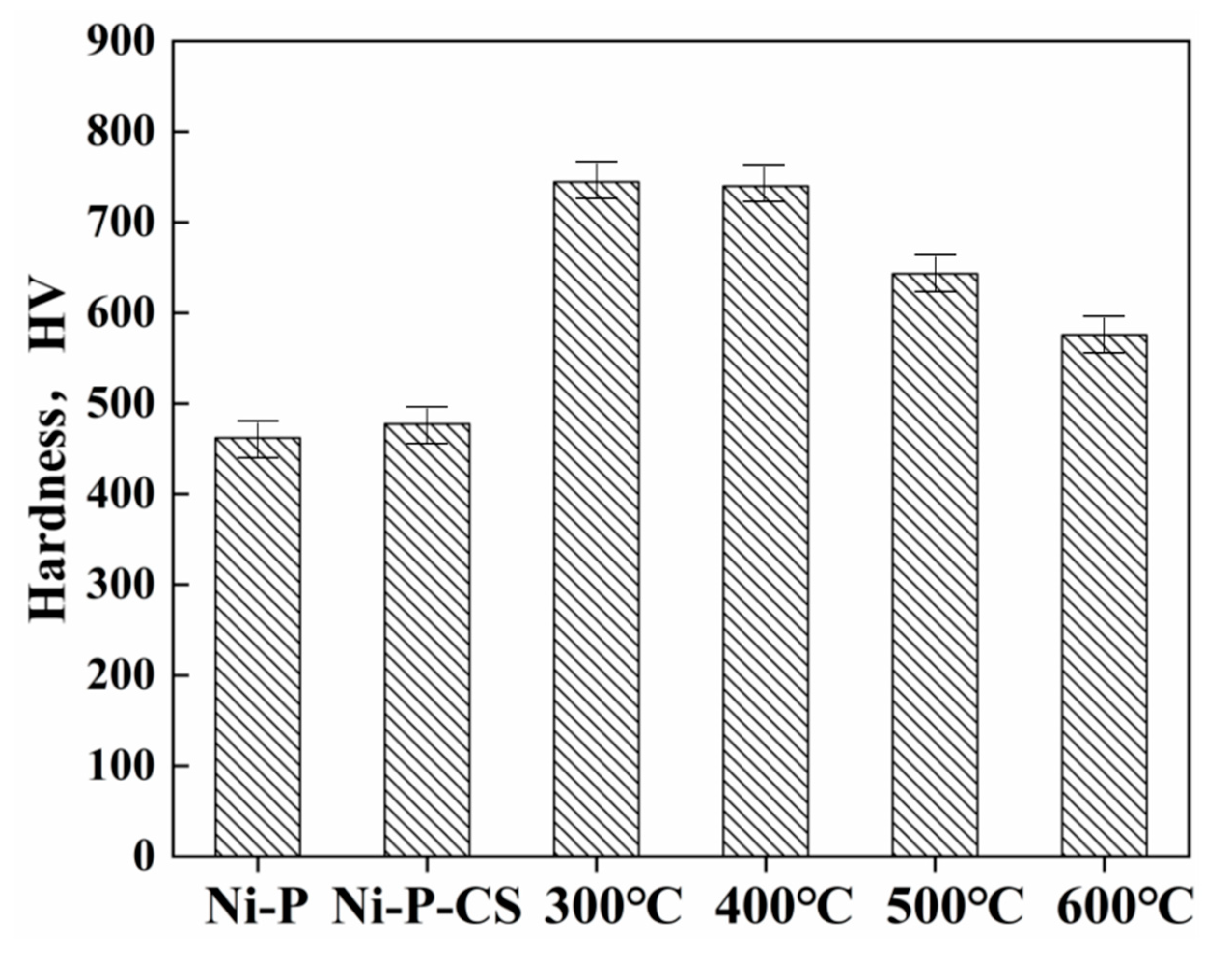
Thermal treatment has been proposed as an approach to enhance the hardness of nickel-phosphorus coatings, and the precipitation of the Ni3P phase was an essential reason for the hardness improvement [12]. Figure 5 illustrates the average microhardness, revealing that the thermal treatment noticeably improved the coatings’ hardness. The heat treatment temperature affected the hardness of the Ni-P-CS coating to a certain extent, but the thermal treatment temperature over 400 °C led to a reduction in the hardness. This result is consistent with that reported in the literature [13].
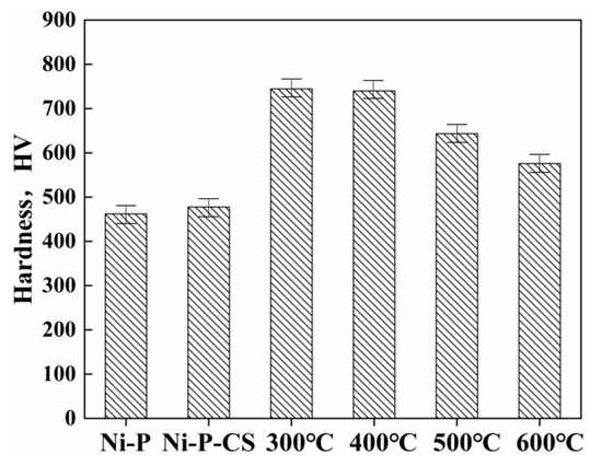
Figure 5.
Microhardness of Ni-P and Ni-P-CS (after heat treatment at different temperatures).
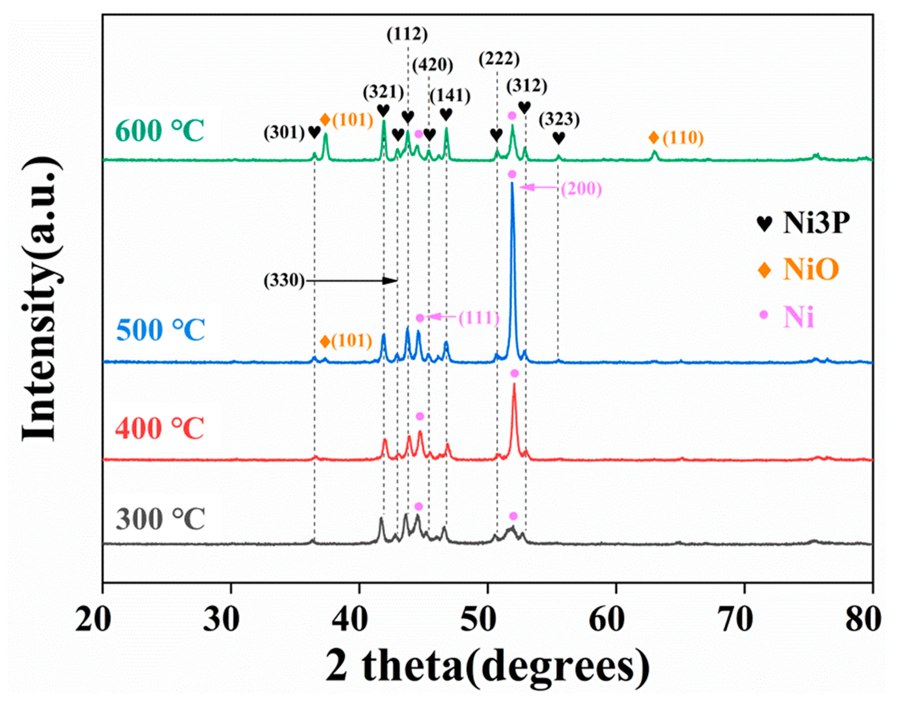
For the heat treatment at 300 °C, the phase composition was mainly in the Ni3P and Ni (111) phases. With the growth of the heat treatment temperature, the absorption peak intensity of the Ni (111) and Ni (200) phases grows up to 400 °C, reaching the maximum at 500 °C, as demonstrated in Figure 6. It is also worth mentioning that the NiO phase appears in the coating when the heat treatment is performed at 500 °C, indicating that the oxidation of the composite coating becomes obvious at this time, with an absorption peak associated with the (101) crystal plane of NiO. As the temperature rises to 600 °C, the absorption peak of the NiO phase is apparently enhanced, and the (110) crystal plane of NiO appears since the composite coating is oxidized at the elevated temperature.
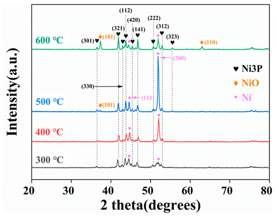
Figure 6.
XRD of Ni-P-CS treated at different temperatures.
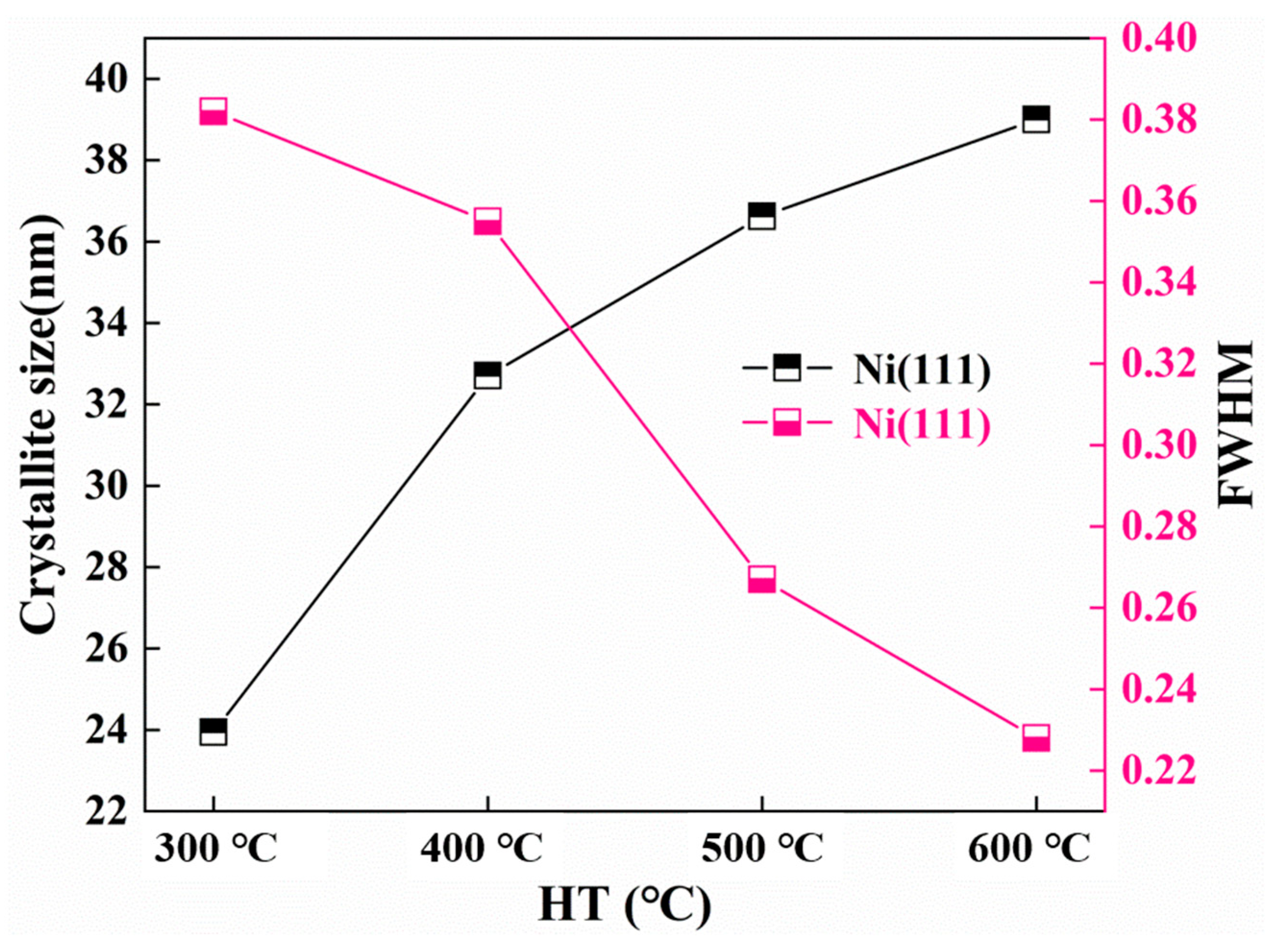
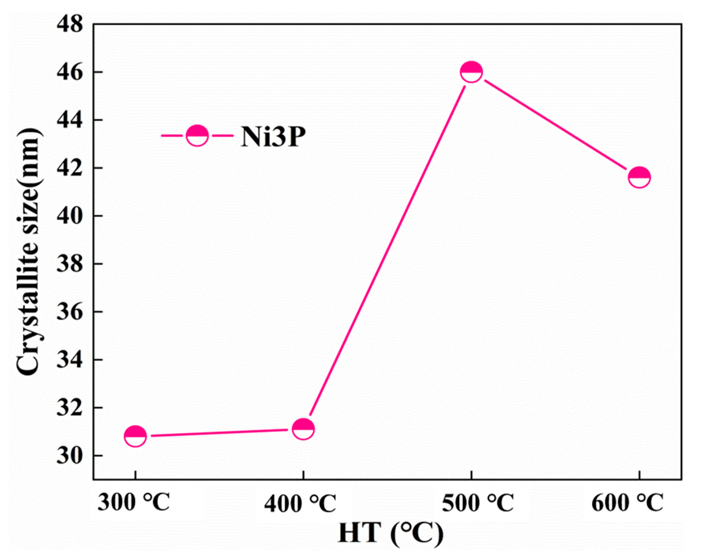
The FWHM and crystallite size of the Ni (111) and Ni3P phase after heat treatment at various temperatures were determined by the proposed formula by the Scherrer formula [14]. The dynamic changes of the crystal size and FWHM of the Ni (111) crystallite size as a function of the temperature change are shown in Figure 7. By increasing the heat treatment temperature, the FWHM of Ni (111) lessens, and the crystal size increases. As can be seen from Figure 8, the influence of the heat treatment temperature on the crystallite size of Ni3P first magnifies and then lessens, reaching the maximum at 500 °C. The overall behaviors of the Ni (111) and Ni3P observed in the present work have been similarly reported in ref. [15].

Figure 7.
Crystallite size and the half-peak full width of Ni (111).
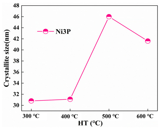
Figure 8.
Crystallite size of Ni3P.
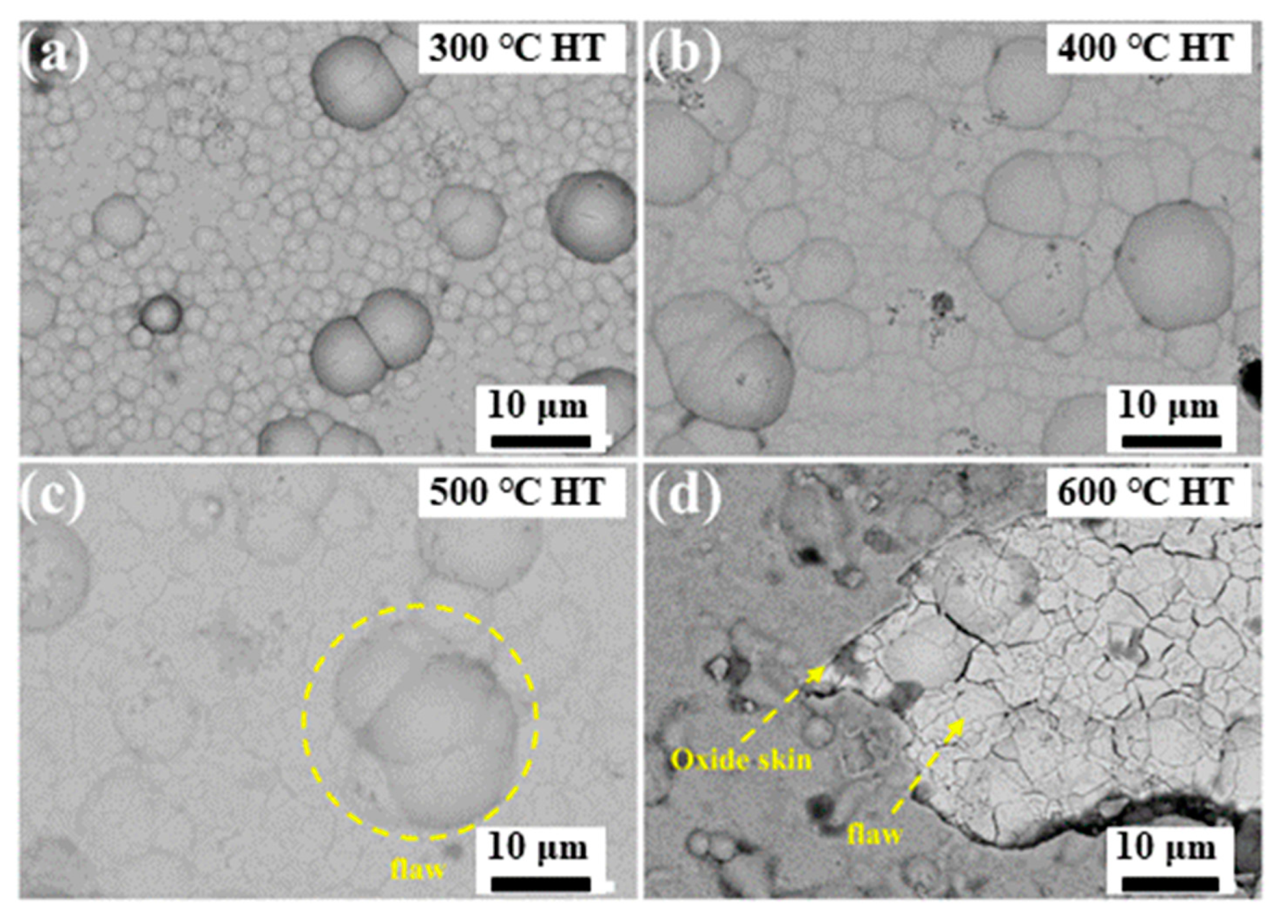
After heat treatment at 300 °C (see Figure 9a), the surface morphology of the composite coatings became more uniform, no obvious cracks and defects were found on the surface, and the composite coating was relatively dense. As the heat treatment temperature increased, grain growth behavior was observed. Compared with the surface morphology of the heat treatment at 300 °C, the cell structure pertinent to the heat treatment at 400 °C becomes remarkably larger. As demonstrated in Figure 9b, no cracks or defects appeared on the coated surface. However, a large area of cracks was detected in the coating starting at 500 °C, but no defects were observed (see Figure 9c). From 600 °C, a large number of oxide skinning and surface defects appeared locally on the coating surface, as illustrated in Figure 9d. Then, the cracks deepened, and the oxide skinning fell off. During the thermal treatment, the escape of carbon dioxide oxidized by the candle soot aggravated the thermal fatigue of the Ni-P-CS coating, resulting in apparent defects on the coating surface.

Figure 9.
Surface morphology of the Ni-P-CS coating after heat treatment at different temperatures. (a) 300 °C Heat Treatment, (b) 400 °C Heat Treatment, (c) 500 °C Heat Treatment, (d)600 °C Heat Treatment.
3.3. Friction Performance of Ni-P and Ni-P-CS Coatings
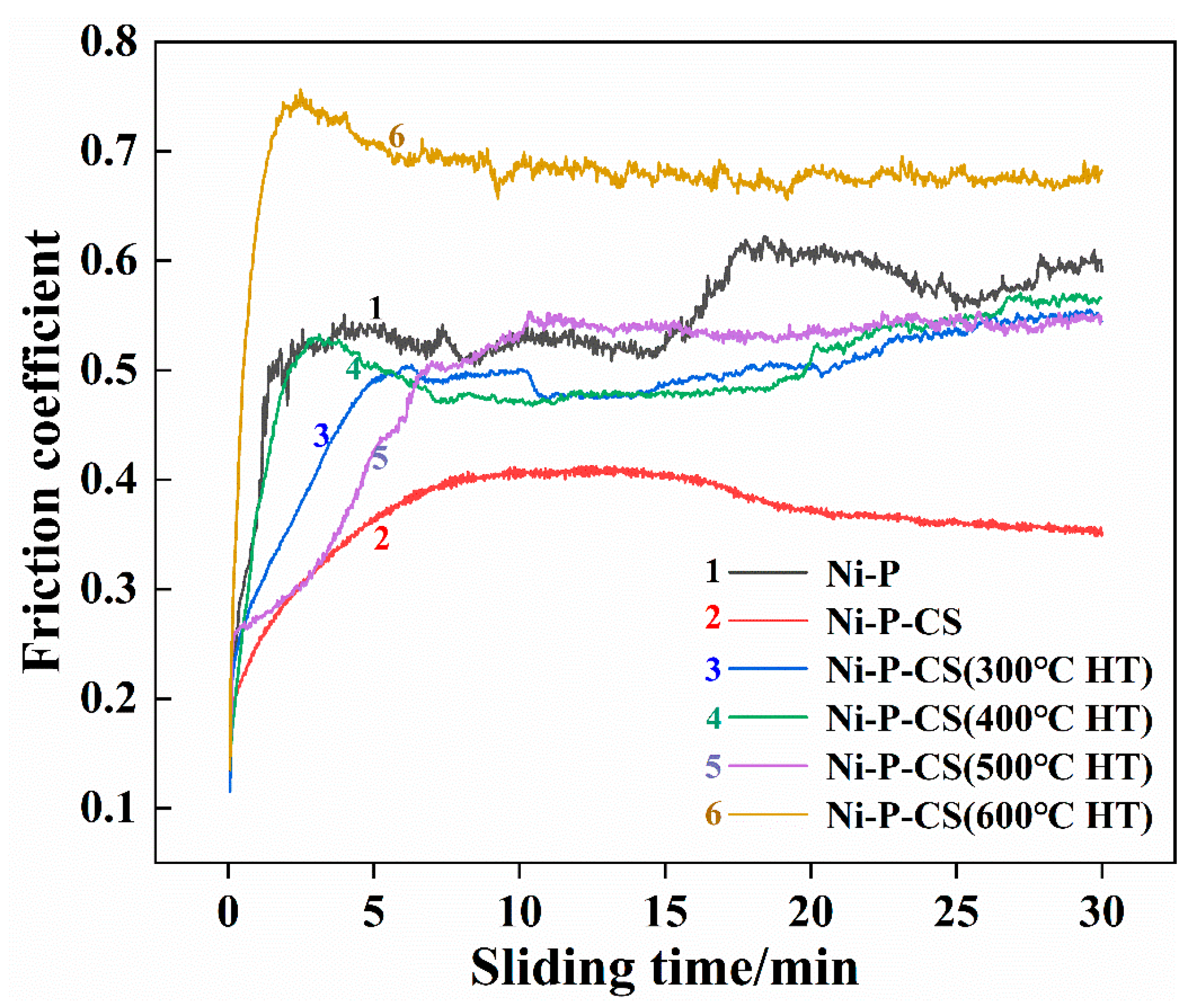
The wear behavior was examined in the domains of friction coefficient and wear extent. As demonstrated in Figure 10, the Ni-P-CS coating exhibited a lower friction coefficient compared with the Ni-P coating. However, the coating after heat treatment showed unsatisfactory wear resistance. One possible reason was that the candle soot was volatilized during the heat treatment, which caused the thermal fatigue of the composite coating to be exacerbated. This phenomenon is consistent with the analysis of the surface morphology after thermal treatment.
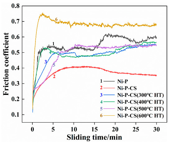
Figure 10.
The friction coefficients of different coatings.
Table 2 presents the weight loss of the wear test for both the Ni-P coating and Ni-P-CS coating. The presented results reveal that the presence of the candle soot effectively yields a decrease in the amount of wear on the coating.
Table 2.
Wear quantity.
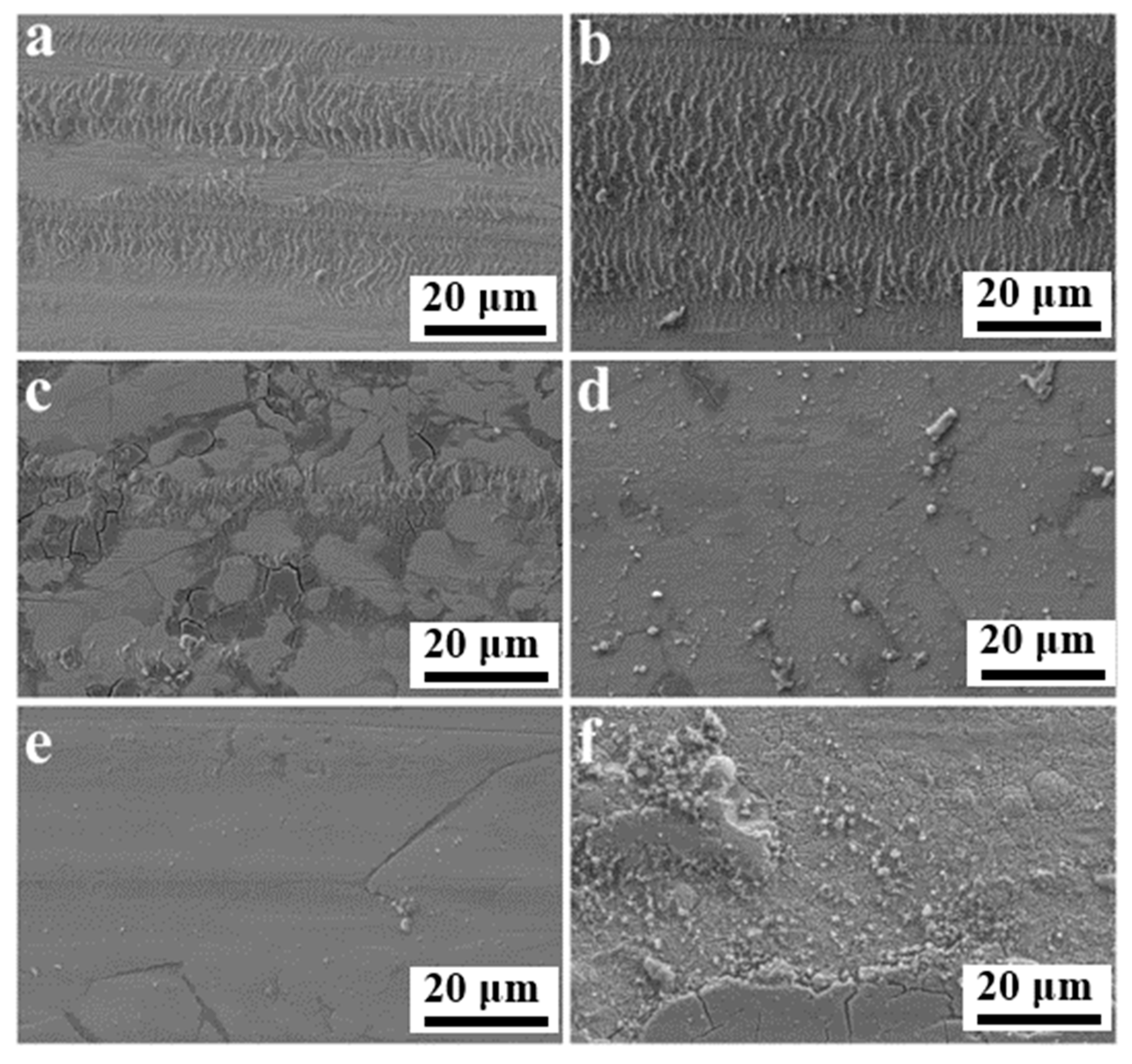
In order to understand the mechanism of wear in coatings, optical and scanning electron microscopy were implemented to explore the pattern of wear traces. The relevant subfigures are presented in Figure 11. The wear behavior of the coatings was adhesive wear and mild abrasive wear. The friction traces shown in Figure 11a,b were extremely similar but differed in the friction coefficient and amount of wear. A comprehensive analysis of the plotted results reveals that the Ni-P-CS coatings with candle soot had better wear resistance, and that candle soot is capable of acting as a solid lubricant during friction. However, the worn morphology of the coating after heat treatment was not promising (see Figure 10c–f). This issue could be explained by the fact that, on the one hand, the coating after heat treatment became defective by the evaporation of the candle soot. On the other hand, due to the increased hardness and surface inhomogeneity of the coating after heat treatment, the tough phase was ground away during the wear process, and the adhesive wear effect was reduced.

Figure 11.
SEM of friction and wear surface of (a) Ni-P, (b) Ni-P-CS, and (c–f) Ni-P-CS composite coatings heat-treated at 300 °C~600 °C.
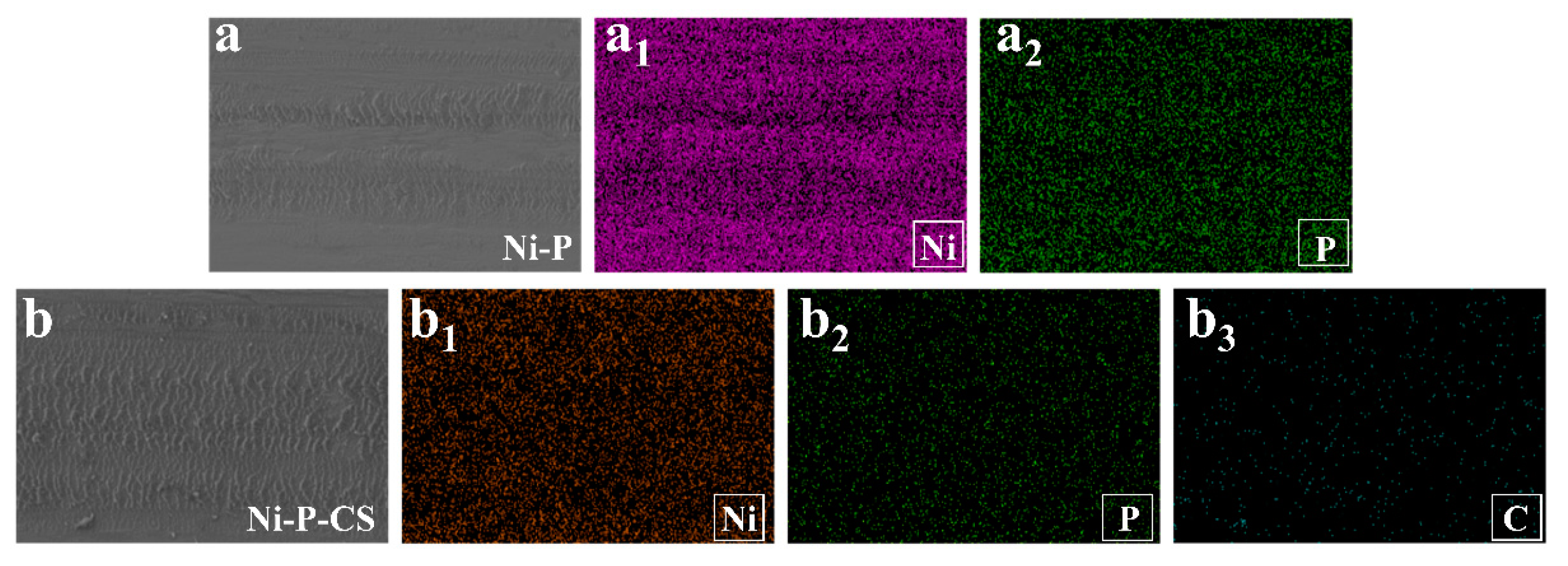
The EDS of wear of the Ni-P coating and Ni-P-CS composite coatings after friction is shown in Figure 12. The reason for the difference in wear resistance between the two coatings is probably because of the carbon in the layers.
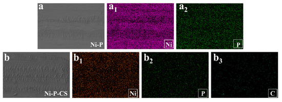
Figure 12.
The EDS after friction and wear of the Ni-P coating and Ni-P-CS composite coatings.((a): SEM of Ni-P coating, (a1): Ni element, (a2): P element, (b): SEM of Ni-P-CS coating, (b1): Ni element, (b2): P element, (b3): C element).
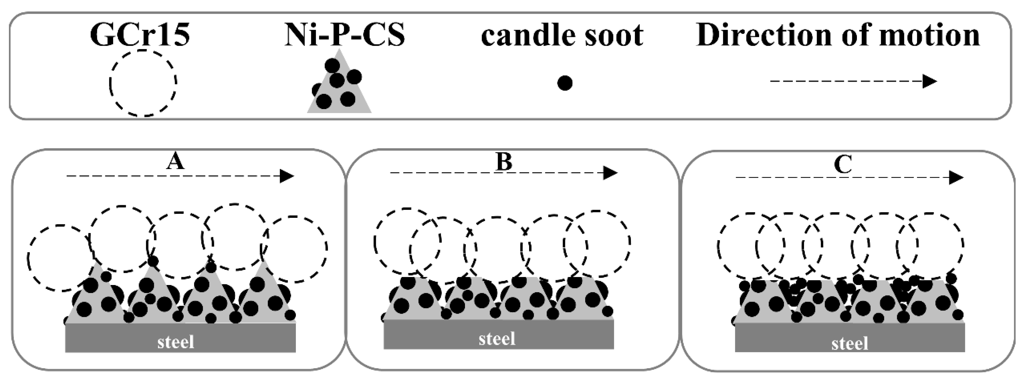
Further comprehensive analysis reveals that the friction mechanism of Ni-P-CS composite coating could be divided into three stages, as illustrated in Figure 13, consisting of the early stage of friction, the middle stage of friction, and the late stage of friction.

Figure 13.
Friction mechanism of the Ni-P-CS composite coatings.
A: The friction pair was in initial contact with the coating surface. During friction and wear, the hardness of the ground material becomes greater than that of the coating, and the softer material will be ground down; this is manifested as the cracking and peeling of the coating. The protrusion on the composite coating surface acts as a bearing, and the coating removed by the grinding enters the next wear with the extrusion and adhesion of the grinding material.
B: With the progress of the friction and wear, due to the grease of the candle soot, the candle soot acts as a solid lubricant between the coating and grinding material, reducing the friction force of the whole system, and thereby the friction coefficient lessens.
C: With the coating being ground down to the grinding material, the candle soot in the coating is squeezed in the wear gap, the coating surface becomes smooth and has a certain lubricity, and the friction coefficient tends stabilize.
4. Conclusions
In this study, the friction and wear behavior of electroless Ni-P and Ni-P-CS composite coatings were studied and the effect of heat treatment on the wear resistance of Ni-P-CS composite coatings was discussed. The results showed that:
- Candle soot can combine well with chemical Ni-P plating.
- The Ni-P-CS composite coatings improved the wear behavior of the Ni-P coating.
- The composite coating of Ni-P-CS effectively reduces the friction coefficient and the amount of wear on the Ni-P coating.
- Thermal treatment improves the hardness of Ni-P-CS coatings but does not reduce the friction coefficient of the coatings.
- The introduction of candle soot particles in the electroless Ni-P coatings produces a significant rise in wear resistance.
Author Contributions
Conceptualization, H.W. and G.L.; methodology, G.L. and H.W.; software, H.W.; validation, X.Z. and G.L.; formal analysis, X.Z. and H.W.; investigation, X.Z. and H.W.; resources, G.L.; data curation, X.Z.; writing—original draft preparation, H.W.; writing—review and editing, X.Z.; supervision, X.Z.; project administration, G.L.; funding acquisition, G.L. and X.Z. All authors have read and agreed to the published version of the manuscript.
Funding
This work was supported by the National Natural Science Foundation of China [21865001], the Key Research and Development Program of Ningxia [2018BEE03017] and Innovation and Entrepreneurship Program for Overseas Returnees of Ningxia [2018711], and the Fundamental Research Funds of the Central Universities, North Minzu University [2019KJ06].
Institutional Review Board Statement
Not applicable.
Informed Consent Statement
Not applicable.
Data Availability Statement
The data presented in this study are available on request from the corresponding author. The data are not publicly available due to all authors’ decisions.
Conflicts of Interest
The authors declare no conflict of interest.
References
- Pancrecious, J.K.; Ulaeto, S.B.; Ramya, R.; Rajan, T.P.D.; Pai, B.C. Metallic composite coatings by electroless technique—A critical review. Int. Mater. Rev. 2018, 63, 488–512. [Google Scholar] [CrossRef]
- Agarwala, R.C.; Agarwala, V. Electroless alloy/composite coatings: A review. Sadhana 2003, 28, 475–493. [Google Scholar] [CrossRef]
- Li, D.Y.; Cui, X.F.; Wen, X.; Feng, L.T.; Hu, Y.T.; Jin, G.; Liu, E.B.; Zheng, W. Effect of CeO2 nanoparticles modified graphene oxide on electroless Ni-P coating for Mg-Li alloys. Appl. Surf. Sci. 2022, 593, 153381. [Google Scholar] [CrossRef]
- Sadreddini, S.; Rahemi Ardakani, S.; Rassaee, H. Corrosion Behavior and Microhardness of Ni-P-SiO2-Al2O3 Nano-composite Coatings on Magnesium Alloy. Mater. Chem. Phys. 2017, 26, 2032–2039. [Google Scholar] [CrossRef]
- Hu, J.; Fang, L. Influences of different reinforcement particles on performances of electroless composites. Surf. Eng. 2016, 8, 362–368. [Google Scholar] [CrossRef]
- Rezagholizadeh, M.; Ghaderi, M.; Heidary, A.; Vaghefi, S.M.M. Electroless Ni-P/Ni-B-B4C duplex composite coatings for improving the corrosion and tribological behavior of Ck45 steel. Prot. Met. Phys. Chem. Surf. 2015, 51, 234–239. [Google Scholar] [CrossRef]
- Valentini, R.; Cavaliere, P.; Valerini, D. Nanoindentation and scratch behaviour of Ni–P electroless coatings. Tribol.-Mater. Surf. Interfaces 2019, 14, 22–32. [Google Scholar] [CrossRef]
- Fanjing, M.; Pang, M.; Ma, L. Application selection of dry film lubricant on carbon steel surface and antifriction mechanism. Ind. Lubr. Tribol. 2020, 74, 868–875. [Google Scholar] [CrossRef]
- Warren, B.E. X-Ray Diffraction; Addison-Weseley Publishing Company: Boston, MA, USA, 1969. [Google Scholar]
- Szasz, A.; Fabian, D.J.; Paal, Z.; Kojnok, J. Chemical mechanisms in electroless deposition: A study on the role of hydrogen in layer formation. J. Non.-Cryst. Solids. 1988, 103, 21–27. [Google Scholar] [CrossRef]
- Palaniappa, M.; Seshadri, S.K. Friction and wear behavior of electroless Ni–P and Ni–W–P alloy coatings. Wear 2008, 265, 735–740. [Google Scholar] [CrossRef]
- Gutsev, D.; Antonov, M.; Hussainova, I.; Grigoriev, A.Y.A. Effect of SiO2 and PTFE additives on dry sliding of NiP electroless coating. Tribol. Int. 2013, 65, 295–302. [Google Scholar] [CrossRef]
- Oguocha, I.N.A.; Taheri, R.; Yannacopoulos, S.; Uju, W.A.; Sammynaiken, R.; Wettig, S.; Hu, Y.F. Temperature effects on the chemical composition of nickel–phosphorus alloy thin films. Thin Solid Film. 2010, 518, 2045–2049. [Google Scholar] [CrossRef]
- Balaraju, J.N.; Rajam, K.S. Surface morphology and structure of electroless ternary NiWP deposits with various W and P contents. J. Alloys Compd. 2009, 486, 468–473. [Google Scholar] [CrossRef]
- Kong, L.; Bi, Q.; Zhu, S.; Yang, J.; Liu, W. Tribological properties of ZrO2 (Y2O3)–Mo–BaF2/CaF2 composites at high temperatures. Ttibol. Int. 2012, 45, 43–49. [Google Scholar] [CrossRef]

Disclaimer/Publisher’s Note: The statements, opinions and data contained in all publications are solely those of the individual author(s) and contributor(s) and not of MDPI and/or the editor(s). MDPI and/or the editor(s) disclaim responsibility for any injury to people or property resulting from any ideas, methods, instructions or products referred to in the content. |
© 2023 by the authors. Licensee MDPI, Basel, Switzerland. This article is an open access article distributed under the terms and conditions of the Creative Commons Attribution (CC BY) license (https://creativecommons.org/licenses/by/4.0/).