Article

Optimization of Femtosecond Laser Drilling Process for DD6 Single Crystal Alloy

1
Science and Technology on Plasma Dynamics Laboratory, Air Force Engineering University, Xi’an 710038, China
2
Key Lab of Advanced Technologies of Materials, Tribology Research Institute, Southwest Jiaotong University, Chengdu 610031, China
*
Author to whom correspondence should be addressed.
Metals 2023, 13(2), 333; https://doi.org/10.3390/met13020333
Submission received: 29 December 2022 / Revised: 3 February 2023 / Accepted: 4 February 2023 / Published: 7 February 2023

Abstract

:
In this paper, we explore the optimal combination of femtosecond laser drilling parameters for micro-hole processing on DD6 single-crystal high-temperature alloy and analyze the significance of parameter variations on the microstructure characteristics of the holes. The L25(56) orthogonal test was performed by controlling six parameters during femtosecond laser ring processing: average power; overlap rate; defocus rate; feed amount; gas pressure; and end position. The significance of the influence of the factors was analyzed by ANOVA, and the parameters were optimized by genetic algorithm. Scanning electron microscopy was performed on the micropores and the salient features of the pores were analyzed. Finally, we calculated the extreme differences and conducted single-factor effect analysis. We conclude that the defocus rate has the most significant level on the hole drilling by femtosecond laser ring processing for DD6 single crystal high-temperature alloy; and the effect of the end position is smaller than others. The optimized parameters are power 6.73 W; overlap 99%, defocus 0 mm; pressure 0.2 MPa; feed 0.02 mm, and end −0.4 mm.

1. Introduction

DD6 single crystal high-temperature alloy has become a key material in the aerospace industry because of its high-temperature strength, good organizational stability, and excellent overall performance, and is widely used in turbine blades and other hot-end components of aero engines [1,2]. As aircraft engines continue to develop to a higher level, the efficiency and thrust-to-weight ratio continue to improve the service temperature of the turbine blades and has put forward higher requirements [3]. The air film hole cooling technology is the main cooling technology applied to engine blades at this stage. However, the air film hole processing is prone to thermal effects, forming micro-cracks, remelting recast layers, and other defects, causing some damage to the surface integrity of the air film cooling hole [4,5,6,7]. Femtosecond laser pulse widths are extremely short, thus preventing thermal diffusion, and it has a minimal thermal effect on the material compared to conventional processes. For DD6 alloy, the electrical discharge machining process is prone to fatigue cracks on both sides of the gas film hole, while the laser hole-making process is more likely to have one-sided fatigue cracks. Internal defects in the recast layer and radial cracks are the most important factors leading to failure [8]. So, the femtosecond laser can process small holes without significant impact around the hole, and unique small hole features can be obtained by controlling the laser parameters. Therefore, for complex hot-end components inside aero-engines, such as high-pressure turbine blades where thousands of gas film holes need to be prepared, micro-hole processing by femtosecond laser on DD6 nickel-based single crystal alloy is of interest [9,10,11].
The effect of current femtosecond laser parameters on single-crystal high-temperature alloys has been studied by scholars to some extent. It has been shown that the diameter increases with increasing single pulse energy in the range of 80 μJ to 130 μJ [12]. The entrance and exit diameters and roundness tend to be stable, while the taper exhibits a slight variation. The defocus rate has a significant effect on the characteristics of the micropores. With the increase of the defocusing rate, the diameter changed considerably. Zhai [13] et al. found a good linear relationship between the number of pulses of the femtosecond laser and the size of the processed nickel-based single crystal material in their study, with the hole diameter becoming larger with an increasing number of pulses. By observing the surface morphology of the sample after the action of femtosecond laser with DD6 single crystal high-temperature alloy, Yu [14] et al. divided the orifice of the small hole processed by femtosecond laser into four regions: ablation region, melting region, laser-induced region, and radiation region, and the mechanism of laser action in different regions is different. In the actual processing, it is not only necessary to select reasonable laser parameters to ensure the processing quality of the micro-hole, but also to select a suitable processing method according to the characteristics of the material and the requirements for the micro-hole [15]. However, the influence law of each laser parameter on the micro-hole quality (such as taper, orifice morphology, etc.) when processing small holes on DD6 alloy by femtosecond laser is still unclear and needs to be studied systematically.
Related studies have shown that changes in important parameters, such as the average power of the laser, overlap rate, and defocus amount, affect the quality of small holes when processing them with femtosecond lasers [16,17,18,19,20,21,22,23,24,25]. There are many factors that affect the quality of laser hole making during processing, and the test could not test all combinations of factors at the same time. So, in this paper, five different sets of test variables under six parameters (average power A, overlap rate B, defocus rate C, feed amount D, gas pressure E, and end position F) were mainly chosen for the experimental study. The relationship between the structural characteristics of the small holes and the femtosecond laser parameters was investigated using the orthogonal test method, and the optimized parameters were subsequently obtained by processing the laser parameters. The experimental results can provide a theoretical basis and guidance for small-hole processing by femtosecond laser on DD6 single-crystal high-temperature alloy.

2. Materials and Methods

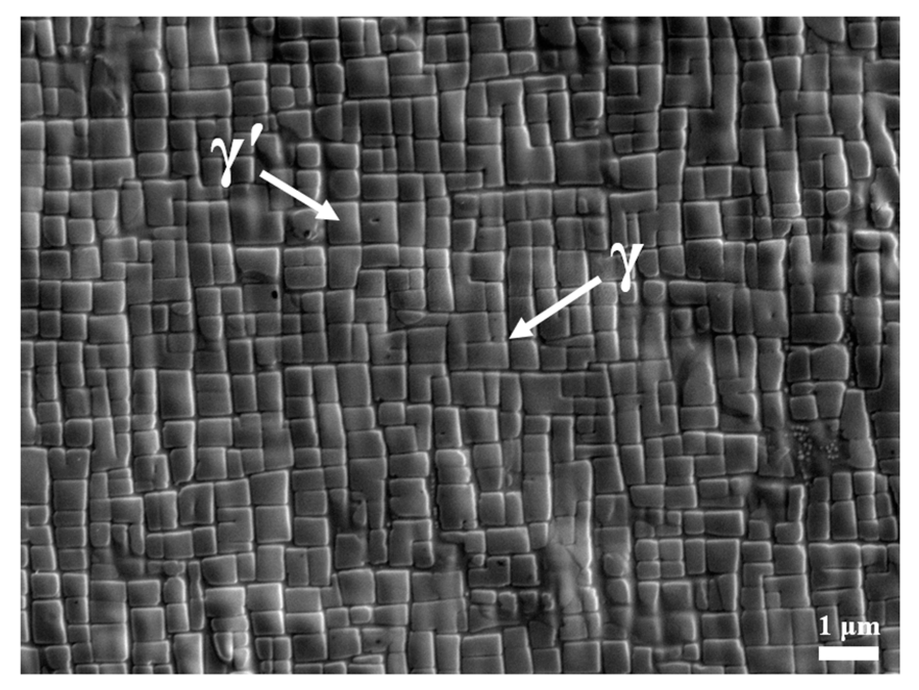
2.1. Experiment Material

In this experiment, DD6 single crystal high-temperature alloy of 20 mm in length, 15 mm in width, and 2 mm in thickness was chosen as the base material, and its chemical composition (in mass fraction) is shown in Table 1.
The microscopic morphology of the sample was observed under the scanning electron microscope (SEM), as shown in Figure 1. It can be observed that the DD6 single crystal high-temperature alloy is mainly composed of γ’ phase and γ phase, where the size of γ’ phase is relatively uniform and no fine secondary γ’ phase is precipitated.

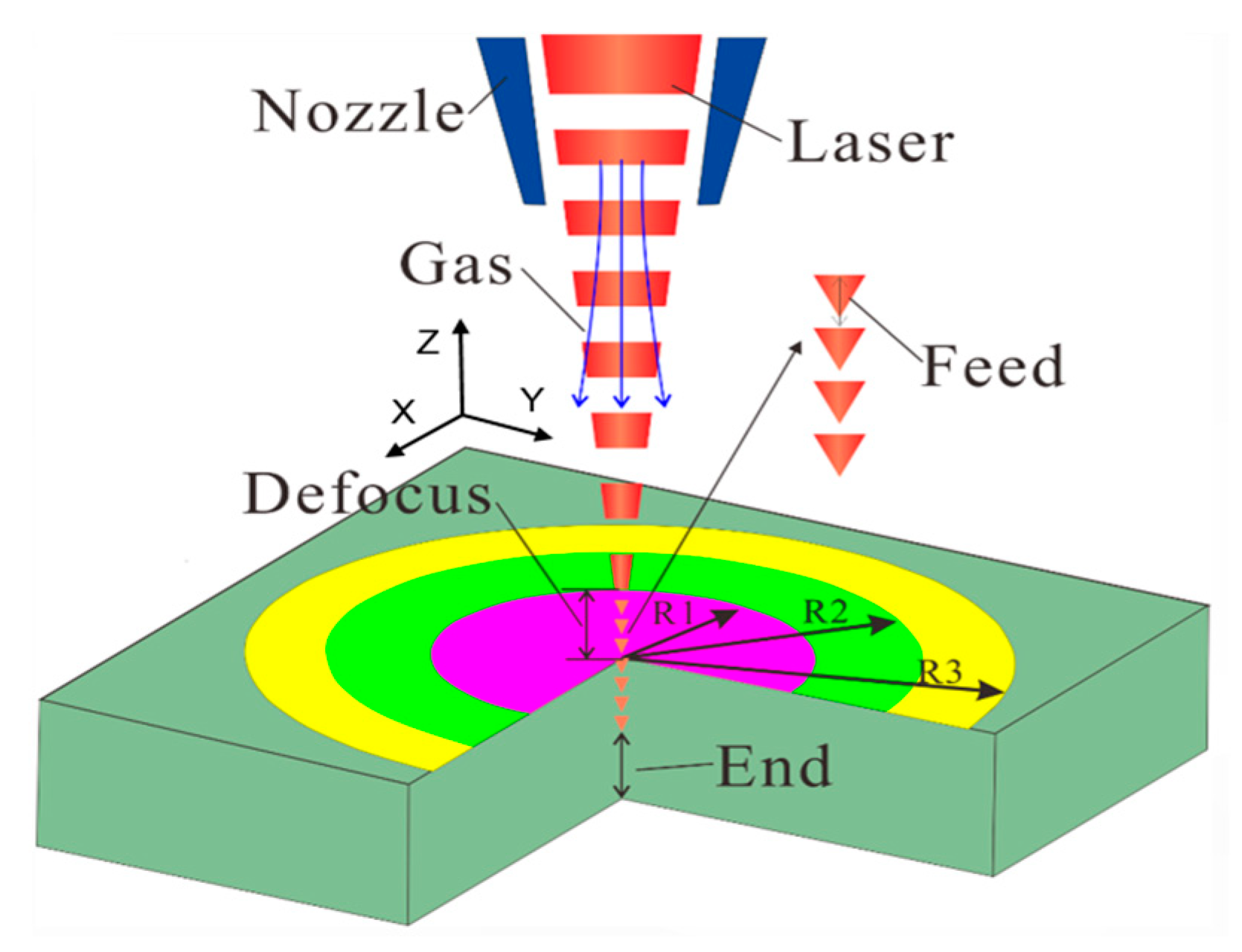
2.2. Hole-Making Process

The experiment uses a femtosecond laser processing system developed solely by Xi’an Institute of Optical Precision, which consists of four main parts: lasers equipment, processing table equipment, computer control equipment, and software system. The optical path diagram is shown in Figure 2. The laser output device is mainly responsible for the laser beam output, as well as the focusing process at the processing platform, which is the core part to realize the micro processing of materials. The processing table is responsible for carrying the sample, which is fixed on the platform. The computer control equipment sends corresponding commands, which can control the table to move along the X, Y, and Z axes, control the on and off of the beam through the optical switch. We use the software system to realize various processing methods, such as micro-hole processing and surface processing. The laser used in the processing is the PHAROS series (Light Conversion Inc, Vilnius, Lithuania).
The experimental laser hole-making method is spiral processing, the main processing process is shown in Figure 3. The test was performed in three stages, where the laser beam was emitted from the top accompanied by an auxiliary gas, and the sample was placed on a movable stage, where the holes were processed sequentially with radius R1, R2, and R3, and at the end of which the holes were processed at the bottom at a set speed for 10 s. In this paper, repeated orthogonal tests were conducted according to the parameters in the factor level table in Table 2, and each group of experiments was repeated three times. The results of the tests were measured, and the average values of the entrance and exit diameters were taken as the resultant hole diameters, respectively, while the taper values were derived using Figure 4 and Equation (1).
Taper = Arctan[(d1 − d2)⁄2L]

2.3. Data Design and Processing Methods

Genetic algorithm (GA) is an adaptive search technique that evolved according to the evolutionary laws of biological reproduction in nature. The GA as a general global solution to the problem of finding the best parameter, as shown in Figure 5, can calculate the fitness value of the population, then rank the fitness of the individuals, and finally find the optimal parameters by selection, crossover, and mutation operations. It is fully feasible and effective in solving global optimization problems under complex situations, such as large-scale, with peaked polymorphic functions, and containing discrete variables. The search approach of GA starts from the population and has the ability to process the problem in parallel, allowing comparisons between multiple individuals to be made simultaneously. The advantage of this over traditional optimization algorithms is that it avoids the possibility of falling into a local optimum solution because of individual solving for the optimal value.
The Taguchi method is a low-cost and highly effective quality engineering method. The orthogonal table is used to select experimental parameters and arrange experiments, and more factors affecting the experimental results are evaluated through fewer parameter combinations. According to the existing research [16,17,18,19,20,21,22,23,24,25], the six parameters shown in Table 2 have a prominent impact on the processing quality. Therefore, we use the Taguchi method to design the parameters of the orthogonal test, and the resulting orthogonal table is shown in Table 2.
In order to process the data efficiently, we used analysis of variance (ANOVA) to analyze the significance of the parameters, and then used analysis of range (ANOR) to try to find the law of influence of each parameter on the quality of hole machining. The mean value of the experimental investigation index (the entrance, exit diameters, and taper) of each factor at different levels was used as the measurement factor. In this paper, we use the GA to perform the optimization search for the optimal parameters, and the entrance and exit diameters of 400 µm and the minimum taper are considered optimal factors.

3. Results

3.1. Results of ANOVA

Table 3 shows the specific grouping of the orthogonal test and the experimental results of each group. The entrance and the exit values are the average values of three independent repetitions of the test, and the taper value is taken from the values under the average value.
The range analysis can simply and visually give the major and minor factors and give a judgment on whether the effect of each factor on the test index is positive or not. However, ANOVA can more accurately provide a criterion for examining and judging whether the effect of each factor is significant or not. The purpose of ANOVA is to find out the factors that have a significant effect through data analysis. This paper uses the ANOVA method to study the most influential factors of the characteristics, and the ANOVA test was carried out with a 95% confidence level and a probability value of (α = 0.05). Statistically, the F-test is an important tool in ANOVA, which can be used to explore which parameters have a significant effect on the characteristics. Usually, when F > 4, it can be tentatively considered that the change of parameters has a significant effect on the characteristics.
The p-value is used to measure the magnitude of the difference with the control group, where the p-value is less than 0.05, it indicates a significant difference, and where the p-value is less than 0.01, it indicates the most significant difference. As shown in Table 4, the results of the comparison of the differences in the levels of entrance, exit, and taper indicators corresponding to different levels in different contexts, respectively, show that the factors corresponding to different levels exhibit different levels of statistically significant differences.
The results of the comparison of differences in the levels of entrance indicators showed that defocus showed the most significant statistical difference (p = 0.000 <0.01), while all other factors were insignificant. The results of the comparison of differences for the level of exit indicators show that both power and defocus (p = 0.000 <0.01) show the most significant statistical difference, and combined with the results of the extreme difference analysis, although both are the most significant level, the defocus has a greater effect on exit. So, the final power is an extremely significant level and all other factors are insignificant. For taper, the defocus (p = 0.003 <0.01) reached the level of the most significant difference along with pressure (p = 0.006 <0.01). Power (p = 0.035 <0.05) and feed (p = 0.023 <0.05) reached the level of significance. A higher F-ratio value implies that the process parameter alteration has caused a significant change in the performance characteristic. Combined with the results of the extreme difference analysis, it can be obtained that the effect of defocus and pressure is the most significant, and defocus is stronger than pressure; the effect of power and feed is significant, and feed is stronger than power. So, the final pressure is at an extremely significant level and all other factors are insignificant.

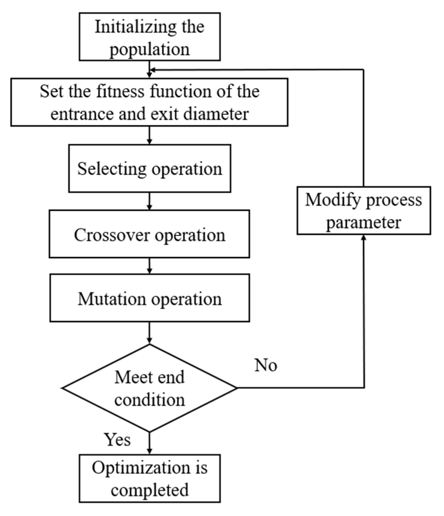
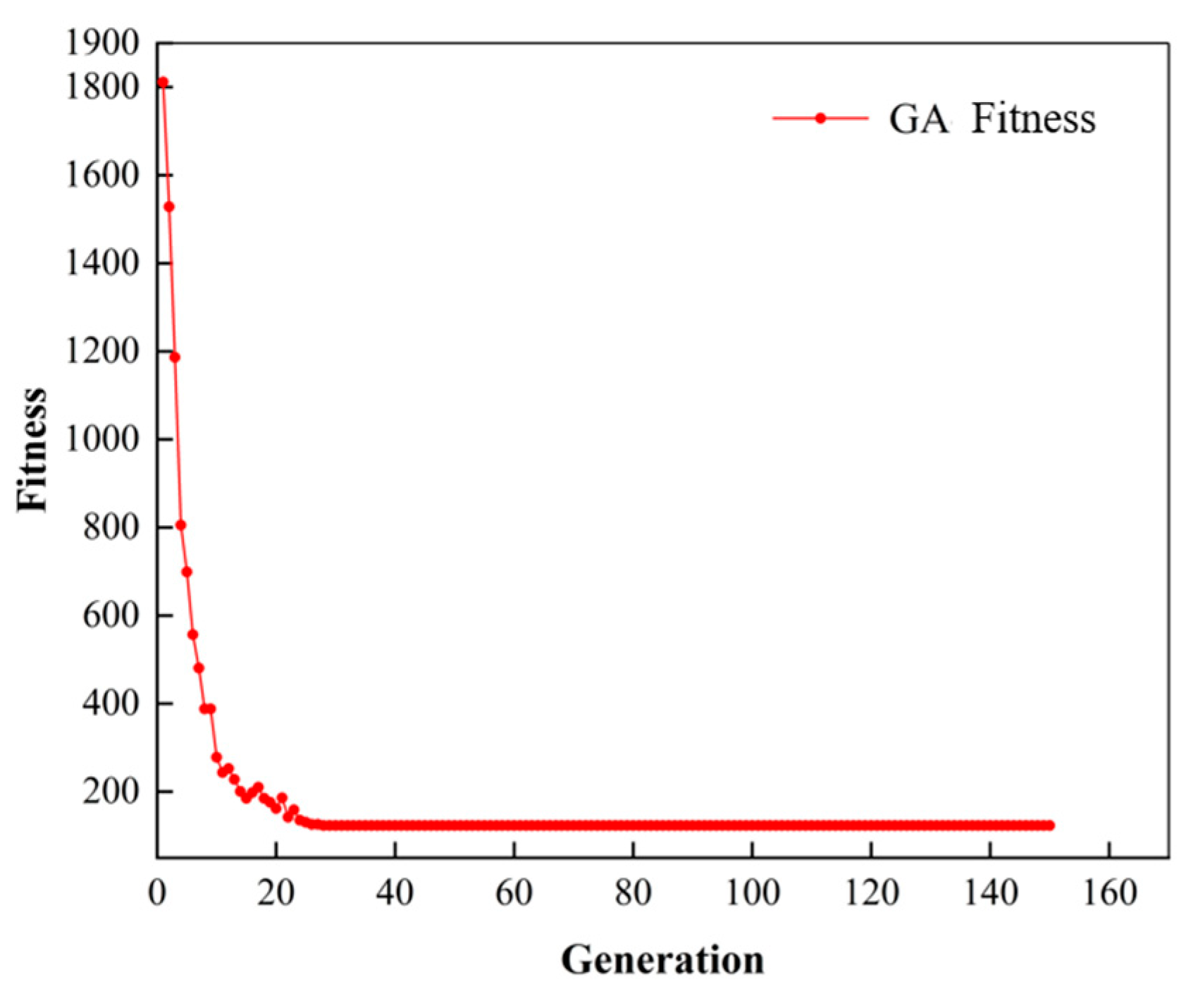
3.2. Parameter Optimization

From Figure 4, it is clear that the parameter optimization of GA includes population initialization, fitness function, selection operator, crossover operator, and mutation operator. The parameters of the genetic algorithm are shown in Table 5, and the populations can be selected with equal probability. The regression equations corresponding to the values of the six variables with the factors are obtained by function fitting, as in Equations (2) and (3). Where E n is the entrance diameter and E x is the exit diameter.
En = 150 + 13.57A + 1.84B + 300.5C − 35.5D − 1565E + 8.2F
(Ex5 − 1 ) (5 × 423.2424) = −169 + 27.37A + 0.71B + 208.3C+ 188D − 2399E + 5.8F
The goal of optimization is to achieve an entrance and exit diameter of 400 μm. Since the entrance diameter is usually used as a statistical object in industry, this paper sets the entrance weight to 0.6 and the exit weight to 0.4, and verifies the taper after obtaining the results. Therefore, the fitness function is:
F = 0.6 × (En − 400)2 + 0.4 × (Ex − 400)2
In this paper, the above regression equation and parameter settings are used to implement the simulation of GA with MATLAB software. Figure 6 shows the optimization process of iterations, which, under the condition of 150 total iterations, shows that the fitness value no longer changes and reaches the minimum value at the 28th generation. The result after optimization by GA is A 1 B 5 C 3 D 1 E 3 F 1 , namely power 6.73 W, overlap 99%, defocus 0 mm, pressure 0.2 MPa, feed 0.02 mm, and end −0.4 mm. The entrance diameter is 387.796 μm, the exit diameter is 406.916 μm, and the taper is −0.273° for this parameter, satisfying the requirements of industrial preparation.

4. Discussion

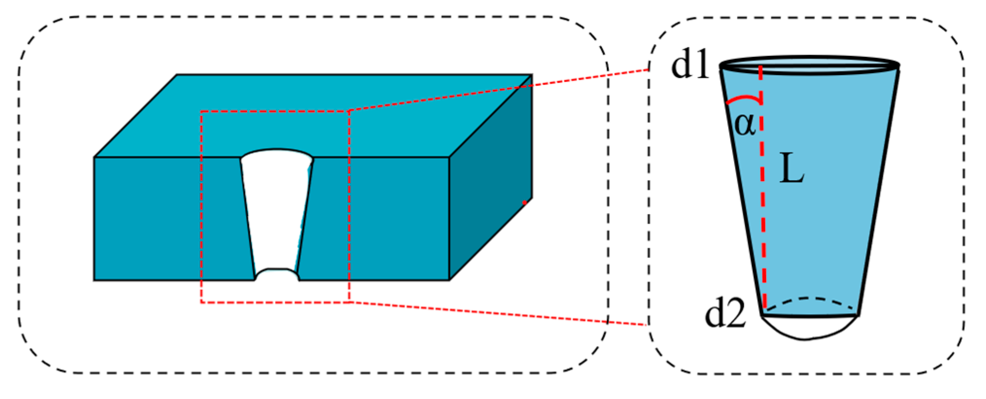
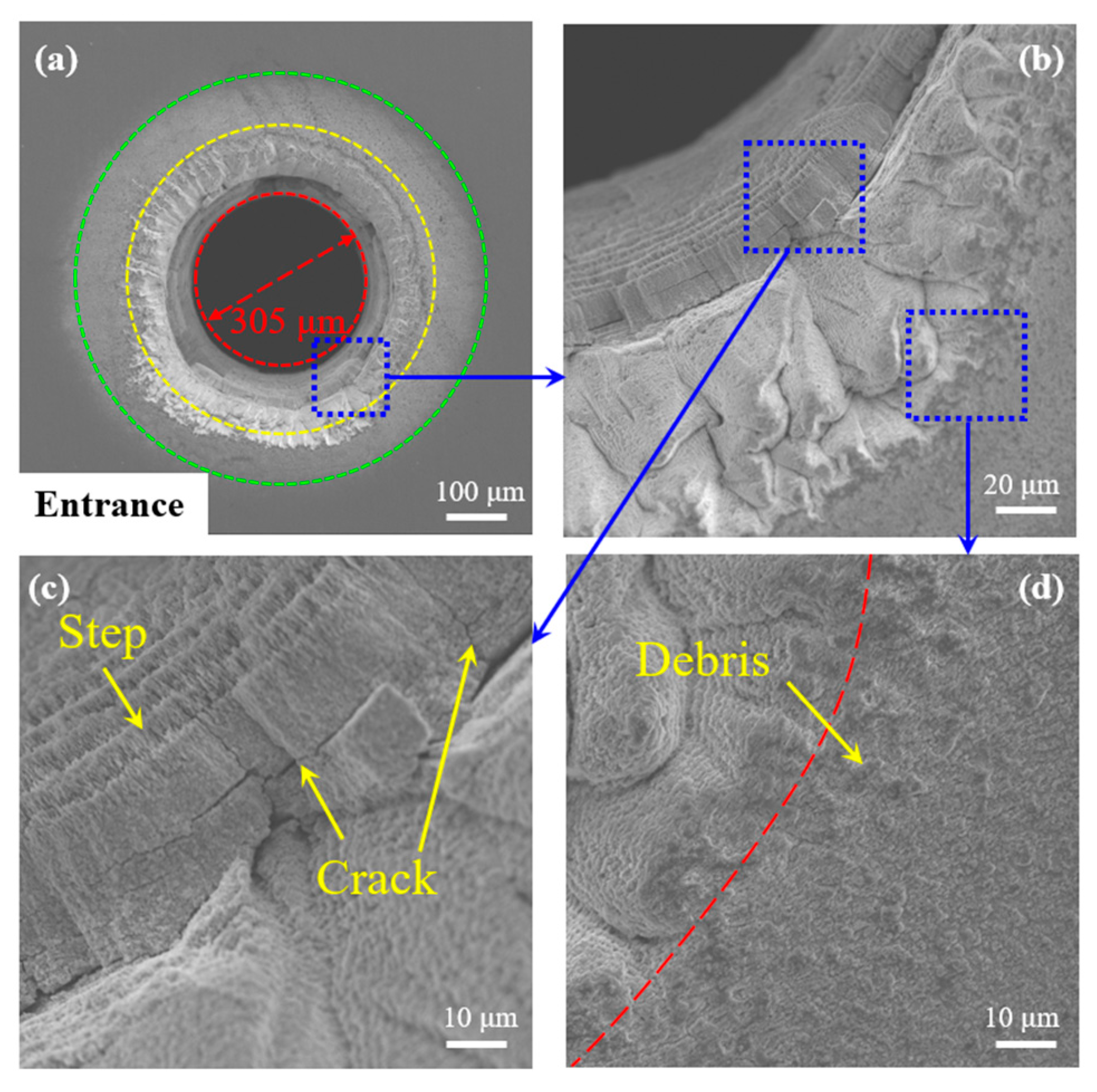
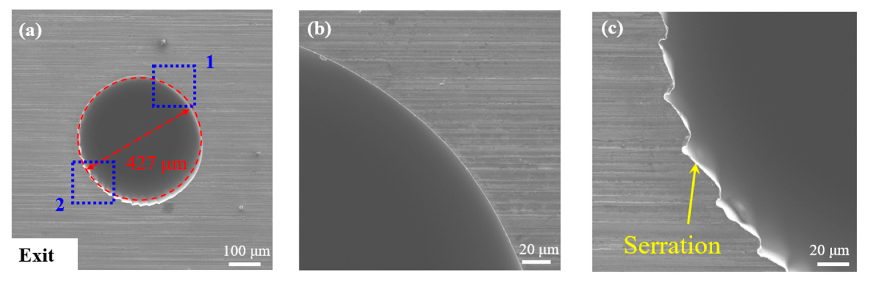
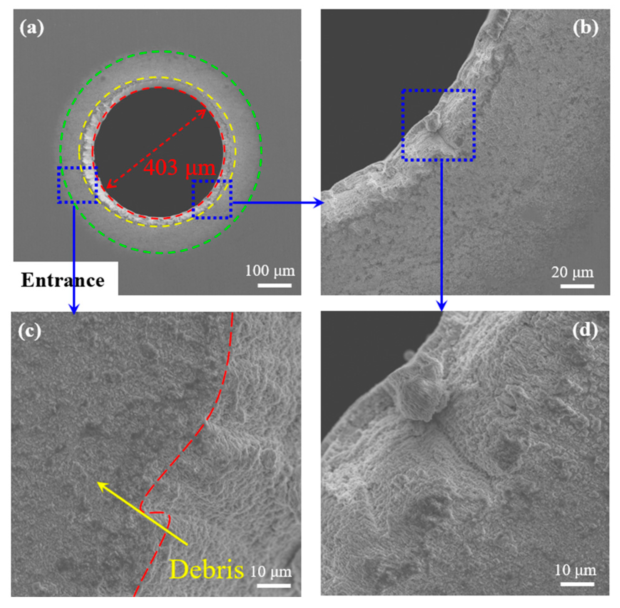
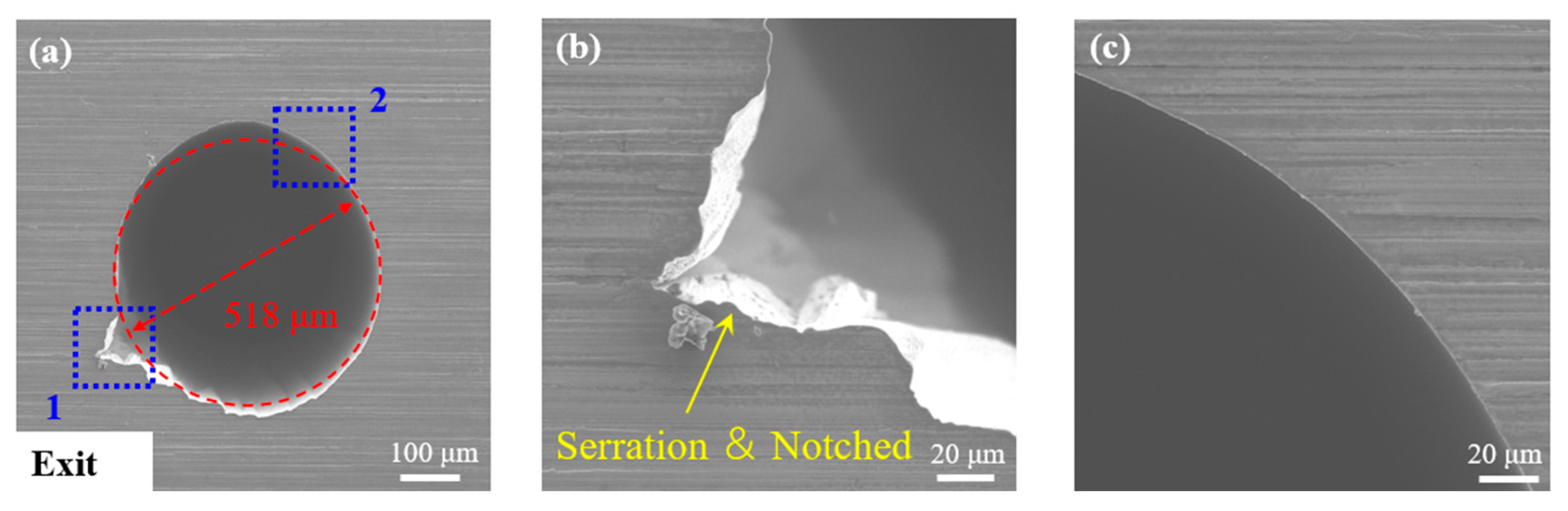
4.1. Morphological Analysis

The macroscopic morphology of the sample after femtosecond laser processing is shown in Figure 7 and the micromorphology results of each group of orifices under the SEM are shown in Figure 8 and Figure 9. Through-hole entrances machined with different process parameters were found to have good roundness, with large variations in entrance diameter, and most entrances produced a stepped structure after machining. Compared to the entrance, the exit is poorly rounded, with an increased variation in diameter and a partially elliptical shape. It can also be observed that when the defocus amount is +0.4 mm (as shown in the reverse diagonal of Figure 8 and Figure 9), the entrance, as well as the exit, always maintains essentially the same dimensions and characteristics regardless of the other parameters. At this time, the roundness is better, the diameter size variation is smaller, and there is almost no stepped structure. However, by the observation of 2-5-1-2-3-4 exits in Figure 9, it did not form an effective exit. After repeated tests, it was verified that this set of parameters could not form an effective through-hole, i.e., power 7.84 W, overlap 99%, defocus −0.4 mm, pressure 0.25 MPa, feed 0.02 mm, and end +0.2 mm. This phenomenon should be related to the Gaussian distribution of the pulsed laser in space. When the defocus is less than −1, the entrance diameter is close to the zero defocus, but the exit diameter is much smaller than the zero defocus [26], which results in a poor removal effect due to the coupling of other parameters.
For better comparative analysis, two through-hole morphologies with typical features and diameters close to 400 µm were selected for micro-area enlargement, as shown in Figure 10, Figure 11, Figure 12 and Figure 13. From the blue enlarged area in Figure 10 and Figure 12, it can be observed that there is a stepped structure at the entrance, and some material inside the hole is not removed. We note that this phenomenon is commonly seen on entrances where the defocus amount is less than 0. This is because when processing with R3, the angle of incidence of the laser increases with regard to the material. According to the Fresnel effect [27], when the angle of incidence of the laser increases, the absorption rate of the material decreases. The pore wall cannot absorb all the energy and the ablation rate gradually decreases [28]. When the energy density absorbed by the material is lower than the ablation threshold, the ablation process ends and the stepped morphology is formed. Therefore, in the actual machining process, we can consider optimizing the feed amount to improve the above situation when machining with R3. Furthermore, some crack generation was found on the internal material (as shown in Figure 10c). These cracks are defects caused by the formation of stepped structures, and the ridge-like accumulation and step-like residue of the orifice were both in the form of nanopillars, but with different orientations, which required further analysis. Figure 11 shows the exit without any accumulation of residue, while some of the edges are smoother and some are serrated. Compared with Figure 10 and Figure 12, there is no visible stepped residual material inside the hole, and the ridge-like accumulation has the same orientation of nanopillars present as the former, but its size is substantially reduced compared to the previous one. Comparing Figure 11 with Figure 13, the basic shape at the exit is consistent. However, it can be observed in Figure 13 that it possesses a notch in addition to the serrated edge. There are also some exits, such as 5-1-5-4-3-2 from Figure 9, that also possess this feature. This damage should be related to the final stopping position of the spiral processing laser rotation, which needs to be verified by further tests.

4.2. Single-Factor Influence Law Analysis

Table 6 shows the analytical calculation results data, which can be derived from the DD6 single crystal high-temperature alloy hole size as well as the extreme difference distribution of taper. Figure 14 shows the influence pattern of different parameters on the DD6 single crystal high-temperature alloy.
Mi is considered as the average of all experimental data under this parameter and R is the range. The relationship between R and Mi is
R = Max (Mi) − Min (Mi)
According to Figure 14a, it can be observed that as the laser power increases, both the entrance and exit diameter increase, with the exit diameter increasing more rapidly, thus leading to a decrease in the taper. Figure 14b shows that the effect of overlap on the entrance diameter is not significant, but the effect on the exit diameter and taper is large, which has no significant pattern. The comparison reveals that the relative slope of the defocus in Figure 14c is the largest, so its effect is the most significant. With the increase of the defocusing amount, both the entrance and exit diameter increase. From Figure 14d, we can see that the gas pressure has little effect on the entrance diameter, but the exit diameter has a greater effect. When observing the samples, it was observed that the exit diameter increases with increasing air pressure greater than 0.25 MPa, which is due to the fact that the larger gas pressure can carry away the plasma more efficiently after the through-hole is formed. According to Figure 14e, it was found that an increase in feed leads to a decrease in the entrance bore diameter, and the experimental results show that when feed was zero, this is beneficial to obtain a through-hole of 400 mm. When the feed is 2mm, there is a data point anomaly; we can guess that this is related to the failure of parameters 2-5-1-2-3-4 to form an effective exit. After removing this group of data and recalculating it, the average value of exit at this time was 451.24mm and the taper was −0.461, which did not affect the basic trend in Figure 14e when compared with the original data. So, the feed of 0.02 mm is beneficial for machining small taper through-holes and smaller exit holes due to increased feed. The increase in the end before 0.2 mm in Figure 14f causes a reduction in the entrance and exit diameters, but its taper has improved. This is the same as the power phenomenon, which is due to the appearance of an increase in taper due to a drop in exit more than in entrance.

5. Conclusions

In this paper, the influence law of femtosecond laser parameters on the hole making of DD6 single crystal high-temperature alloy was studied by an orthogonal test, the optimization of relevant parameters was carried out, and significance evaluation was performed using ANOVA. The following conclusions were drawn:
(1)
The optimal parameters after GA optimization are power 6.73 W, overlap 99%, defocus 0 mm, pressure 0.2 MPa, feed 0.02 mm, and end −0.4 mm. For this parameter, the entrance diameter is 387.796 μm, the exit diameter is 406.916 μm, and the taper is −0.273°.
(2)
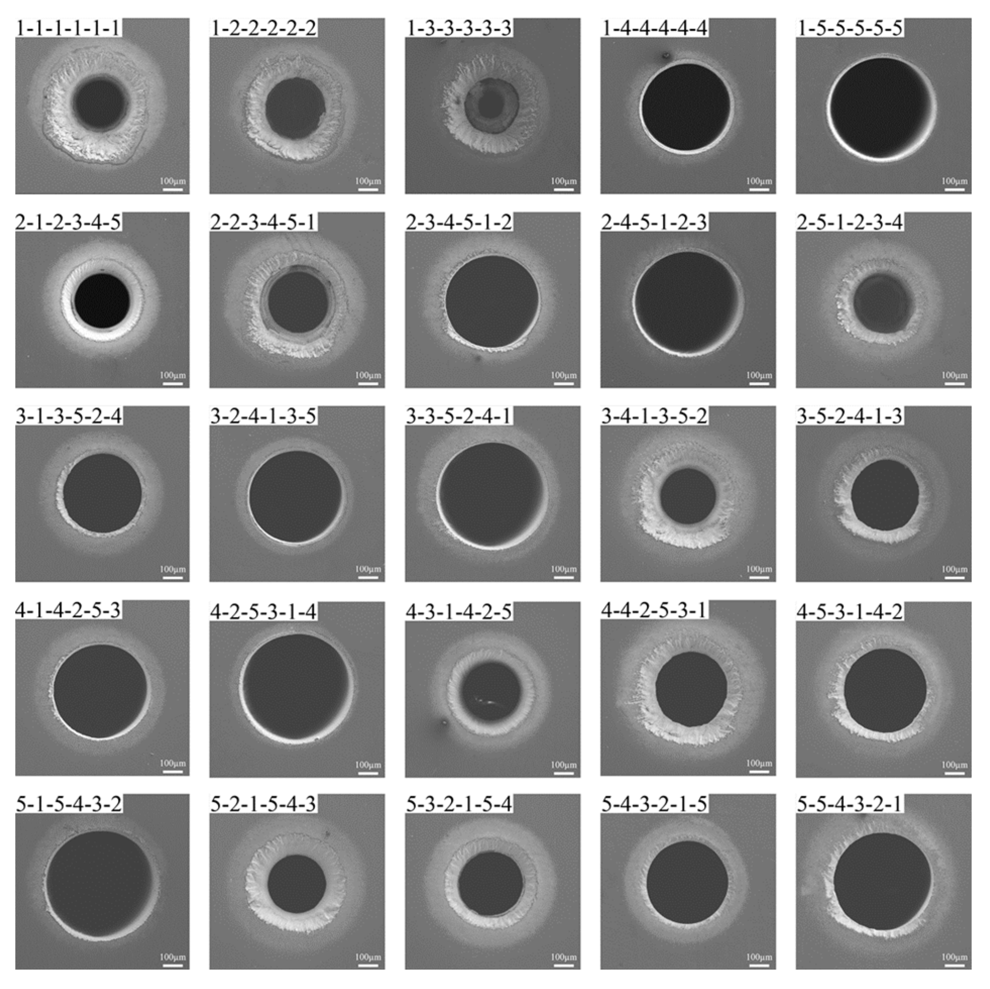
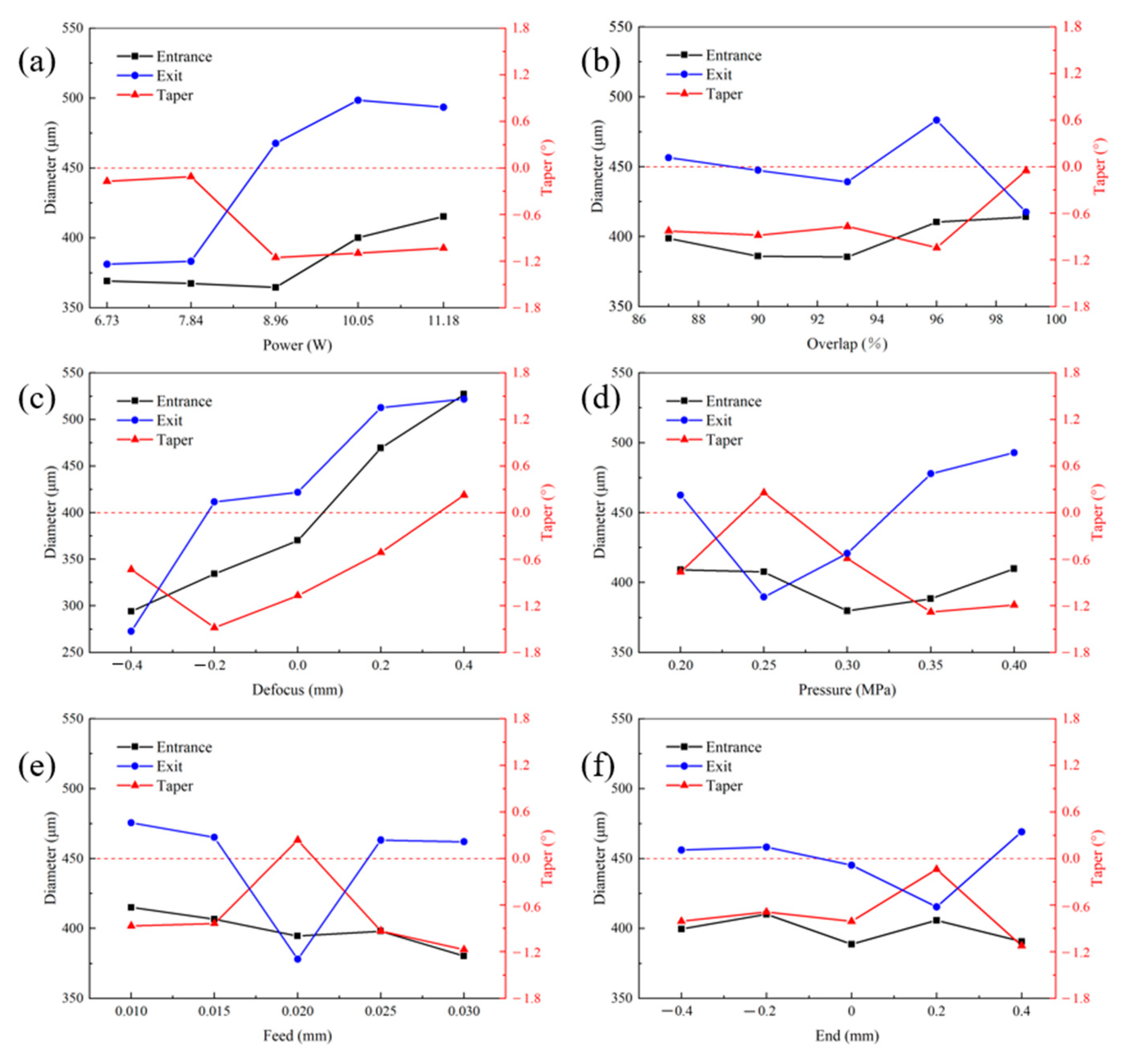
The through-hole entrances processed under different process parameters have good roundness, but the diameters have large variations, and the exits have no accumulation of residues and are poorly rounded, almost all being elliptical in shape, while some jagged edges exist. In response to the increase in the exit diameter after the gas pressure is greater than 0.25 MPa, this is related to the fact that the larger gas pressure can carry away the plasma more effectively after the through-hole is generated.
(3)
The increase in the laser power causes an increase in the entrance and exit diameters, but the exit diameter increases more rapidly, thus leading to a decrease in the taper. The feed of 0.02 mm is beneficial for machining small taper through-holes, and the end position has less effect on the structural characteristics.
(4)
For the entrance and the exit, the defocus has the most significant level; as well as, the power, which has the most significant level for the exit. For taper, the defocus is also the most significant level, and the level of pressure is the same as the defocus. The power and feed are significant levels.

Author Contributions

Conceptualization, T.D. and X.L.; formal analysis, X.L., L.W., W.J. and X.P.; methodology, L.Z. and Z.C.; resources, L.Z.; validation, Y.Y. and Z.C.; writing—original draft preparation, T.D. All authors have read and agreed to the published version of the manuscript.

Funding

This research was funded by the “National Science and Technology Major Project of China, grant number J2019-III-0008-0051”; and “the Natural Science Foundation of China, grant number 51875574”.

Institutional Review Board Statement

Not applicable.

Informed Consent Statement

Not applicable.

Data Availability Statement

The data used to support the findings of this study are available from the corresponding author upon request.

Acknowledgments

The authors gratefully acknowledge financial support from the National Science and Technology Major Project of China [J2019-III-0008-0051]; and the Natural Science Foundation of China [51875574].

Conflicts of Interest

The authors declare no conflict of interest.

References

  1. Shi, Z.X.; Liu, S.Z.; Li, J.R. Rejuvenation Heat Treatment of the Second-Generation Single-Crystal Superalloy DD6. Acta Metall. Sin. (Engl. Lett.) 2015, 28, 1278–1285. [Google Scholar] [CrossRef]
  2. Li, J.; Zhong, Z.; Tang, D.; Liu, S.Z.; Wei, P.; Wu, Z.T.; Huang, D.; Han, M. A Low-cost second geneution single crystal superalloy DD6. Superalloys 2000, 777–783. [Google Scholar]
  3. Xia, W.; Zhao, X.; Yue, L.; Zhang, Z. Microstructural evolution and creep mechanisms in Ni-based single crystal superalloys: A review. J. Alloys Compd. 2020, 819, 152954. [Google Scholar] [CrossRef]
  4. Pei, H.; Wang, J.; Li, Z.; Li, Z.; Yao, X.; Wen, Z.; Yue, Z. Oxidation behavior of recast layer of air-film hole machined by EDM technology of Ni-based single crystal blade and its effect on creep strength. Surf. Coat. Technol. 2021, 419, 127285. [Google Scholar] [CrossRef]
  5. Zhang, Q.; Sun, S.-F.; Zhang, F.-Y.; Wang, J.; Lv, Q.-Q.; Shao, Y.; Liu, Q.-Y.; Shao, J.; Liu, X.-F.; Zhang, Y. A study on film hole drilling of IN718 superalloy via laser machining combined with high temperature chemical etching. Int. J. Adv. Manuf. Technol. 2019, 106, 155–162. [Google Scholar] [CrossRef]
  6. Abbas, N.; Solomon, D.; Bahari, M. A review on current research trends in electrical discharge machining (EDM). Int. J. Mach. Tool. Manu. 2007, 47, 1214–1228. [Google Scholar] [CrossRef]
  7. Zhigilei, L. Dynamics of the plume formation and parameters of the ejected clusters in short-pulse laser ablation. Appl. Phys. A 2003, 76, 339–350. [Google Scholar] [CrossRef]
  8. Li, F.; Zhang, Y.; Wu, Z.; Ren, X.; Yue, X.; Pei, H.; Yue, Z. Fatigue crack initiation and propagation behavior of nickel-based single crystal DD6 under different drilling processes. Mater. Sci. Eng. A 2022, 831, 142246. [Google Scholar] [CrossRef]
  9. Feng, Q.; Picard, Y.N.; Liu, H.; Yalisove, S.M.; Mourou, G.; Pollock, T.M. Femtosecond laser micromachining of a single-crystal superalloy. Scr. Mater. 2005, 53, 511–516. [Google Scholar] [CrossRef]
  10. Feng, Q.; Picard, Y.N.; McDonald, J.P.; Van Rompay, P.A.; Yalisove, S.M.; Pollock, T.M. Femtosecond laser machining of single-crystal superalloys through thermal barrier coatings. Mater. Sci. Eng. A 2006, 430, 203–207. [Google Scholar] [CrossRef]
  11. Wang, R.; Dong, X.; Wang, K.; Sun, X.; Fan, Z.; Duan, W. Investigation on millijoule femtosecond laser spiral drilling of micro-deep holes in thermal barrier coated alloys. Int. J. Adv. Manuf. Technol. 2021, 114, 857–869. [Google Scholar] [CrossRef]
  12. Yin, C.; Wu, Z.; Dong, Y.; You, Y.; Liao, T. Femtosecond laser helical drilling of nickel-base single-crystal super-alloy: Effect of machining parameters on geometrical characteristics of micro-holes. Adv. Prod. Eng. Manag. 2019, 14, 407–420. [Google Scholar] [CrossRef]
  13. Zhai, Z.; Wang, W.; Mei, X.; Li, M.; Li, X. Percussion drilling on nickel-based alloy with thermal barrier coatings using femtosecond laser. Optik 2019, 194, 163066. [Google Scholar] [CrossRef]
  14. Yu, Y.Q.; Zhou, L.C.; Cai, Z.B.; He, W.F. DD6 single-crystal superalloy with thermal barrier coating in femtosecond laser percussion drilling. Opt. Laser Technol. 2021, 133, 106555. [Google Scholar] [CrossRef]
  15. Zhang, F.; Wang, J.; Wang, X.; Zhang, J.; Hayasaki, Y.; Kim, D.; Sun, S. Experimental study of nickel-based superalloy IN792 with femtosecond laser drilling method. Opt. Laser Technol. 2021, 143, 107335. [Google Scholar] [CrossRef]
  16. Qi, H.; Lai, H. Micromachining of metals and thermal barrier coatings using a 532 nm nanosecond fiber laser. Phys. Procedia 2012, 39, 603–612. [Google Scholar] [CrossRef]
  17. Harilal, S.S.; Freeman, J.R.; Diwakar, P.K.; Hassanein, A. Femtosecond laser ablation: Fundamentals and applications. In Laser-Induced Breakdown Spectroscopy; Springer International Publishing: Berlin/Heidelberg, Germany, 2014; pp. 143–166. [Google Scholar]
  18. Ionin, A.; Kudryashov, S.I.; Seleznev, L.V.; Sinitsyn, D.V.; Bunkin, A.F.; Lednev, V.N.; Pershin, S.M. Thermal melting and ablation of silicon by femtosecond laser radiation. JETP Lett. 2013, 116, 347–362. [Google Scholar] [CrossRef]
  19. Povarnitsyn, M.; Fokin, V.; Levashov, P. Microscopic and macroscopic modeling of femtosecond laser ablation of metals. Appl. Surf. Sci. 2015, 357, 1150–1156. [Google Scholar] [CrossRef]
  20. Wang, S.Y.; Ren, Y.; Cheng, C.W.; Chen, J.K.; Tzou, D.Y. Micromachining of copper by femtosecond laser pulses. Appl. Surf. Sci. 2013, 265, 302–308. [Google Scholar] [CrossRef]
  21. Kelly, R.; Miotello, A. Comments on explosive mechanisms of laser sputtering. Appl. Surf. Sci. 1996, 96, 205–215. [Google Scholar] [CrossRef]
  22. Oh, B.; Kim, D.; Kim, J.; Lee, J.-H. Femtosecond laser ablation of metals and crater formation by phase explosion in the high-fluence regime. Phys. Conf. Ser. 2007, 59, 567. [Google Scholar] [CrossRef]
  23. Cheng, C.; Xu, X. Molecular dynamic study of volumetric phase change induced by a femtosecond laser pulse. Appl. Phys. A 2004, 79, 761–765. [Google Scholar] [CrossRef]
  24. Cheng, C.; Xu, X. Mechanisms of decomposition of metal during femtosecond laser ablation. Phys. Rev. B 2005, 72, 165415. [Google Scholar] [CrossRef]
  25. Putzer, M.; Ackerl, N.; Wegener, K. Geometry assessment of ultra-short pulsed laser drilled micro-holes. Int. J. Adv. Manuf. Technol. 2021, 117, 2445–2452. [Google Scholar] [CrossRef]
  26. Zhang, Z.; Wang, W.; Jiang, R.; Jin, C. Experimental Study on Geometric Precision of Microholes Drilling by Picosecond Laser. In Proceedings of the ASME International Mechanical Engineering Congress and Exposition, Salt Lake City, UT, USA, 11–14 November 2019. [Google Scholar]
  27. Verbeeck, J.; Bertoni, G.; Schattschneider, P. The Fresnel effect of a defocused biprism on the fringes in inelastic holography. Ultramicroscopy 2008, 108, 263–269. [Google Scholar] [CrossRef]
  28. Fan, N.; Xia, Z.; Sun, X.; Hu, Y. Experimental study on stainless steel micro-hole trepanned by femtosecond laser. Laser Infrared 2016, 46, 1200–1205. [Google Scholar]
Figure 1. SEM image showing the microstructure of test sample.
Metals 13 00333 g001
Figure 2. Optical path diagram of femtosecond laser processing.
Metals 13 00333 g002
Figure 3. Schematic diagram of annular drilling.
Metals 13 00333 g003
Figure 4. Schematic diagram of taper calculation.
Metals 13 00333 g004
Figure 5. Femtosecond laser process parameters optimization flow chart with genetic algorithm.
Metals 13 00333 g005
Figure 6. Training results of GA algorithm.
Metals 13 00333 g006
Figure 7. Macro morphology of femtosecond laser drilling samples (a) front; (b) back.
Metals 13 00333 g007
Figure 8. Morphology of femtosecond laser entrance hole.
Metals 13 00333 g008
Figure 9. Morphology of femtosecond laser exit hole.
Metals 13 00333 g009
Figure 10. Enlarged view of the 2-2-3-4-5-1 entrance hole morphology micro area (a) entrance hole; (bd) enlarged view.
Metals 13 00333 g010
Figure 11. Enlarged view of the 2-2-3-4-5-1 exit hole morphology micro area (a) exit hole; (b) area 1; (c) area 2.
Metals 13 00333 g011
Figure 12. Enlarged view of the 3-1-3-5-2-4 entrance hole morphology micro area (a) entrance hole; (bd) enlarged view.
Metals 13 00333 g012
Figure 13. Enlarged view of the 3-1-3-5-2-4 exit hole morphology micro area (a) exit hole; (b) area 1; (c) Area 2.
Metals 13 00333 g013
Figure 14. Effect of relevant parameters on DD6 single crystal superalloy. (a) power; (b) overlap; (c) defocus; (d) pressure; (e) feed; (f) end.
Metals 13 00333 g014
Table 1. Chemical composition of the DD6 single crystal alloy used in this study.
ElementCrTaWMoReAlNbHfNi
Content4.506.787.362.002.045.681.010.10bal
Table 2. Factors and levels.
LevelsFactors
Power A
(W)
Overlap B
(%)
Defocus C
(mm)
Pressure D
(MPa)
Feed E
(mm)
End F
(mm)
16.7387−0.40.200.010−0.4
27.8490−0.20.250.015−0.2
38.96930.00.300.0200.0
410.05960.20.350.0250.2
511.18990.40.400.0300.4
Table 3. Orthogonal design and measurement results of DD6 single crystal superalloy.
NumABCDEFEntrance (μm)Exit (μm)Taper (°)
1111111290.97333.04−0.603
2122222319.07335.37−0.234
3133333292.95265.090.399
4144444446.43482.09−0.511
5155555496.18490.080.087
6212345282.24386.82−1.498
7223451304.95427.36−1.753
8234512470.45510.33−0.571
9245123522.70506.690.229
10251234296.6585.013.029
11313524403.49518.34−1.645
12324135462.00505.96−0.630
13335241530.13503.050.388
14341352286.75313.10−1.809
15352413352.98497.67−2.072
16414253471.61513.10−0.594
17425314540.53525.180.220
18431425292.14450.8−2.271
19442531375.83502.62−1.815
20453142428.53500.58−1.032
21515432545.56531.290.204
22521543303.35443.59−2.008
23532154341.63466.54−1.789
24543215420.37511.64−1.307
25554321496.07514.29−0.261
Table 4. ANOVA results for each factor.
SymbolSum of SquaresMean SquareFPSig.
EntrancePower A37,997.15918,338.691.0750.376
Overlap B10,662.17011,895.440.2890.884
Defocus C560,708.462141,549.20102.1630.000**
Pressure D11,685.43212,136.640.3170.866
Feed E10,347.26111,821.220.280.89
End F5173.17910,601.610.1390.967
ExitPower A222,670.80864,684.836.1740.000**
Overlap B34,762.32720,392.110.7430.566
Defocus C269,519.63775,727.768.0720.000**
Pressure D108,975.52237,885.222.5600.046
Feed E95,686.3534,752.782.2090.077
End F25,150.77118,126.530.5310.713
TaperPower A16.4565.6142.7420.035*
Overlap B8.8943.8311.3830.249
Defocus C24.5667.5254.4360.003**
Pressure D22.6107.0654.0020.006**
Feed E17.9955.9773.0430.023*
End F7.7573.5641.1940.321
The ** is the most significant level, and the * is the significant level.
Table 5. Parameters of genetic algorithm.
Population SizeMaximal Hereditary GenerationCrossover ProbabilityMutation Probability
401500.90.1
Table 6. Extreme difference analysis for each factor.
ProjectsFactors
Power A
(W)
Overlap B
(%)
Defocus C
(mm)
Pressure D
(MPa)
Feed E
(mm)
End F
(mm)
Entrance diameter (mm) k 1 369.118398.770293.971409.166415.060399.589
k 2 367.371385.980334.349407.566406.690410.069
k 3 364.547385.460370.056379.706394.600388.717
k 4 400.047410.420469.311388.410398.130405.745
k 5 415.302414.082527.017409.858380.220390.586
Range50.75528.623233.04630.15234.83821.354
Exit diameter (mm) k 1 381.134456.522345.106462.562475.572456.072
k 2 383.242447.493437.801389.632465.110458.132
k 3 467.624439.163444.601420.895377.990445.227
k 4 498.456483.235505.155477.841463.234415.430
k 5 493.470417.528511.258492.990462.030469.059
Range117.32265.7020166.152103.35897.57753.629
Taper
(°)
k 1 −0.172−0.827−0.733−0.764−0.867−0.809
k 2 −0.113−0.881−1.4810.256−0.836−0.688
k 3 −1.154−0.769−1.068−0.5900.237−0.809
k 4 −1.098−1.043−0.513−1.281−0.932−0.139
k 5 −1.032−0.0500.226−1.190−1.172−1.124
Range1.0410.9931.7071.5371.4090.985
Disclaimer/Publisher’s Note: The statements, opinions and data contained in all publications are solely those of the individual author(s) and contributor(s) and not of MDPI and/or the editor(s). MDPI and/or the editor(s) disclaim responsibility for any injury to people or property resulting from any ideas, methods, instructions or products referred to in the content.

