Article

Cutting Parameters Optimization for Minimal Total Operation Time in Turning POM-C Cylindrical Stocks into Parts with Continuous Profile Using a PCD Cutting Tool

by
Milan Trifunović
1,
Miloš Madić
1,
Dragan Marinković
2,* and
Velibor Marinković
1
1
Faculty of Mechanical Engineering in Niš, University of Niš, 18000 Niš, Serbia
2
Department of Structural Analysis, Technical University Berlin, 10623 Berlin, Germany
*
Author to whom correspondence should be addressed.
Metals 2023, 13(2), 359; https://doi.org/10.3390/met13020359
Submission received: 29 December 2022 / Revised: 27 January 2023 / Accepted: 6 February 2023 / Published: 10 February 2023
(This article belongs to the Section Metal Casting, Forming and Heat Treatment)

Abstract

:
Turning is a complex machining process that can be characterized by a number of performances for a given machining system, workpiece material, cutting tool, and selected cutting regime. In addition to the characteristics of the machined surface quality, the estimation of machining time is particularly important for manufacturers, since machining time is directly related to other important performances of the turning process, such as productivity, cost, and energy consumption. In this paper, a model for estimation of total operation time in turning of a part with continuous profile, made of polyoxymethylene copolymer (POM-C), using a polycrystalline diamond (PCD) cutting tool, was developed. Face centred central composite design (CCD) and Box–Cox transformation approaches were applied for that purpose. The developed model was then used as the objective function in the proposed optimization model, which also included three practical constraints related to quality of the machined surface (surface roughness and workpiece deflection) and machinability aspects of the workpiece material (favourable chip forms). Nonlinear and linear models, used as constraints, were developed based on the results of experimental investigation of turning of POM-C using a PCD cutting tool. The total operation time estimation model showed good agreement with the results of tool path simulations in CAM software and validation experimental trial in real manufacturing environment. By applying the optimal solution, 44% of the total time being saved for machining of a single part can be achieved, compared to the recommended cutting parameter values, which indicates significant optimization benefits in turning industrial plastics.

1. Introduction

Companies in the machining industry strive to manufacture high-quality parts in a short time with minimal costs [1], although these are conflicting goals and not easily achievable simultaneously in practice in many cases. In this regard, special attention is paid to the optimization of the machining processes [2]. Turning is the most common machining process. In this machining process, the material is removed from the surface of a rotating workpiece by using a single-point cutting tool. The resulting geometry is determined by the feed trajectory of the cutting tool. The magnitudes of primary (rotational) and feed (linear) motion are defined by the values of the cutting speed and feed rate, which, together with the depth of cut, form a set of technological cutting parameters.
Turning is a complex process with multiple inputs and outputs [3]. This is reflected in numerous studies that deal with the analysis of various performances and phenomena in the turning process. These studies involved different workpiece materials, operations, cutting regimes, cutting fluid types and supply strategies, tools geometries and grades, machining methods and strategies. Different constraints, related to the required specifications of the finished part, cutting tool, and machine tool were also considered in studies.
A group of studies with experimental and theoretical considerations can be distinguished. Sitarz and Powalka [4] analysed processing efficiency in turning of noncircular cross-section workpieces using different machining strategies. In order to analyse how feed rate and cutting speed affect quality characteristics (surface roughness, roundness and cylindricity of machined surface) of five different workpiece materials, Zmarzly [5] proposed the application of technological heredity concept. Khanna et al. [6] compared conventional flood coolant, minimum quantity lubrication (MQL), and cryogenic coolant (liquid carbon dioxide) based on machinability criteria (tool wear, surface roughness, and cutting forces) for the turning of Ti-6Al-4V alloy. The effects of cutting speed and magnetic flux density values on machining stability (measured as vibration amplitude and other related parameters), surface roughness, chip forms, and cutting temperature in the turning of AISI 4140 steel were analysed by Sofuoglu and Cakir [7]. Agrawal et al. [8] made comprehensive analysis of tool wear, power consumption, surface roughness, machining costs, and carbon emissions in turning Ti-6Al-4V titanium alloy under cryogenic and wet conditions. The effects of workpiece material heat treatment and coolant pressure on cutting forces, tool wear, chip formation, and surface roughness for turning of Haynes 282 superalloy were analysed by Suárez et al. [9]. Das et al. [10] performed a comparative evaluation of machinability (cutting temperature, tool wear, surface roughness, chip morphology, and principal cutting force) and machining cost in dry turning of hardened AISI D6 die steel using conventional TiCN-coated insert and insert with supernitride nanocomposite HSN2-TiAlxN coating. Storchak et al. [11] proposed a methodology for determining the tool-chip contact length, an important parameter which ultimately affects friction and heat transfer, using an experimental and numerical simulation study. A comprehensive study to identify the best insert grades and chipbreakers for turning of Inconel 718, considering cutting forces, tool wear, surface roughness, and surface integrity, was performed by Fernández-Valdivielso et al. [12]. Mallick et al. [13] made a comparative evaluation of CVD- and PVD-coated carbide inserts in the hard turning of AISI D2 steel, considering tool wear, tool life, surface roughness, and surface texture. A life cycle assessment (LCA) for sustainability analysis and investigation of energy consumption with varying feed rate and cutting speed for eight different cooling techniques in turning of precipitation hardened stainless steel (PHSS) was performed by Khanna et al. [14]. Mia et al. [15] presented an experimental work regarding the investigation of three sustainable techniques and one traditional cutting fluid supply strategy on cutting temperature, surface roughness, chip forms, and tool wear in the turning of hardened AISI 1060 steel. Tool wear effects on surface integrity and surface roughness for the dry turning of AISI 1045 steel were examined by Magalhães et al. [16]. Kim et al. [17] analysed tool wear, tool life, machining cost, and CO2 emissions in the cryogenic-assisted hard turning of AISI 52100 steel. Rahman et al. [18] investigated the mechanics of chip formation in the turning of aluminium alloy using different machining strategies. Ranjan and Hiremath [19] performed an in-depth experimental analysis of the effects of different coated carbide tools and parameters (cutting speed, feed, and depth of cut) on tool wear, cutting forces, surface roughness, surface defect, residual stresses, and chip morphology. Pereira et al. [20] compared the combination of cryogenic cooling and MQL with other near-to-dry machining techniques for the turning of AISI 304 stainless steel considering cutting forces, tool wear, and surface integrity. Uysal and Jawahir [21] proposed a novel slip-line model for the analysis of machining mechanics in the orthogonal turning of AISI 304 stainless steel under different cooling/lubricating conditions. Different empirical models were developed for the analysis of power, energy, CO2 emissions, and production costs. Kuruc et al. [22] investigated the effects of cutting parameters on chip compression and plastic deformation during the turning of carbon and tool steels. Leksycki et al. [23] analysed the material side flow phenomenon in the finish turning of AISI 316L stainless steel by applying the parameter space investigation (PSI) method for experimental research. Suárez et al. [24] compared insert wear patterns during the face-turning of IN 718 nickel-based alloy using conventional and high-pressure cooling. An experimental analysis of the effects of cutting parameters on surface integrity, characterized by surface roughness, residual stresses, microhardness and microstructure, in turning Inconel 718 using ceramic and carbide inserts, was performed by Tan et al. [25].
Studies from the second group deal with modelling and optimization. Fernando et al. [26] performed an L9 orthogonal array design to analyse and optimize energy consumption, cutting fluid consumption, surface roughness and material removal rate in wet and dry turning of AISI P20 steel. The analysis of the effects of feed rate, depth of cut and cutting speed on surface integrity (surface roughness, residual stresses, and white layer) and cutting forces in the hard turning of AISI 4317 case carburized, quenched, and tempered steel was performed by Branco et al. [27]. Arora et al. [28] performed a full factorial design to analyse and model the relationships between cutting parameters (cutting speed, feed rate and depth of cut) and surface roughness and generated noise level in the wet turning of EN-19 alloy steel using PVD-TiN-coated mixed ceramic (Al2O3 + TiCN) inserts. Tzotzis et al. [29] developed and investigated the relationship between cutting speed, feed rate, and depth of cut and cutting force components in the turning of AISI 4140 steel using both the finite element method (FEM) and empirical modelling based on the use of response surface methodology (RSM). A comparison of machining performance, in terms of surface roughness, cutting temperature and material removal rate, between conventional and high-speed turning of Ti6Al4V alloy using polycrystalline diamond (PCD) tool was made by Abdelnasser et al. [30]. An experimental investigation and prediction of machining performances, such as cutting force components, tool flank wear, surface roughness, and chip thickness, using the hybrid deep convolutional neural network was performed by Palaniappan and Subramaniam [31]. A machinability and sustainability analysis of high-pressure coolant assisted turning of Inconel 718 was investigated by Cica and Kramar [32]. The effects of cutting parameters on surface roughness, chip reduction coefficient and cutting forces in turning of 100Cr6 bearing steel using advanced C-type cutting tools was analysed by Bhandarkar et al. [33]. Chen and Hsu [34] applied the uniform design method to perform a machining experiment and investigate the effects of cutting speed, feed rate, and depth of cut on tool wear, surface roughness, machining time and cutting forces in turning of nickel alloy. Rafighi [35] investigated the cutting sound effect on surface roughness, power consumption, and cutting force in dry turning of Ti-6Al-4V titanium alloy. A holistic sustainability assessment of lubrication (Al-GnP nanofluid) and cooling (cryogenic LN2) approaches in turning of Ti-6Al-4V alloy was performed by Khan et al. [36]. The turning of martensitic stainless steel X20Cr13 was analysed by Sterpin-Valic et al. [37] to determine optimal cutting regime, cutting fluid type, and supply strategy that minimize surface roughness and tool life while maximizing material removal rate at the same time. Hadjela et al. [38] used different optimization methods to find cutting parameter values resulting in minimum surface roughness and flank wear and maximum material removal rate, when turning AISI 4140 alloy steel. Palacios et al. [39] used two approaches to determine stable cutting regimes resulting in an optimal material removal rate for the turning of Inconel 718 using SNMG and VBMT inserts. Dragičević et al. [40] investigated the influence of minimum quantity lubrication and cooling (MQLC) parameters (oil and water flow) on surface roughness and resultant cutting force for the turning of St 50-2 steel.
Table 1 gives an overview of recent research aspects in turning.
Recent review papers provide a detailed insight into the state of research regarding certain aspects of the turning process and machining processes in general, such as cutting tool coatings [44], machining of hardened steels [45], artificial intelligence systems for tool condition monitoring [46], cutting fluid types and supply strategies [47,48,49,50], sustainable machining of titanium and its alloys [51], energy consumption [52], and techniques for chatter avoidance [53].
Workpiece materials used in recent studies were mainly metals. The most researched aspect of the turning process recently was the quality of the machined surface, followed by machining mechanics (cutting forces), tool wear, and chip formation. One can also notice an increased interest in machining economics and surface integrity. This is not surprising, since there is a constant demand for high-quality products that would preferably be accessible to a wider range of customers on the market.
Based on the data in Table 1, one can conclude that machining time was not a well-studied aspect of the turning process recently. On the other hand, it is a particularly important aspect of the turning process, related to many other aspects as well. Machining time, multiplied by shop rate (sum of machine tool costs and labour costs), determines the machining cost [54], which is another important aspect of the machining economy. For some specific products, such as plastic injection moulds, machining time has the greatest impact on the total tool cost [42]. There is also a relationship between machining time and profit rate. Energy consumed during machining, which is directly proportional to machining time, and energy embodied in consumed resources are responsible for carbon emissions [36]. The machining time is also used as an indicator to the tool wear and tool life. The quality of the machined surface and machining time were rated as more important than reduction of energy consumption in a survey of end mills manufacturers and users [55]. According to some studies, decreasing the process time increases energy efficiency to a greater extent than decreasing the process load [56].
The machining time is the function of three cutting parameters and the total tool path [57]. However, it is highly nonlinear, and there is no analytical expression for the machining of varying part geometry [58]. There is a lack of tools for machining time estimation, especially in situations where small series of parts are manufactured, where geometry and required machining operations change from series to series [59].
Armillotta [41] improved machining time estimation in the early stage of product development by combining complexity, expressed as a function of part dimensions and tolerances, with three additional parameters: the total area of the machined features, the envelope volume of the part, and the workpiece material. The proposed regression model predicted machining time with an average error of 25%, compared to a feature-based method, for sample parts of different sizes, geometries, and materials, involving several machining processes.
Known analytical models for machining time cannot be used for parts with complex geometry. Moreover, the development of analytical models is usually time-expensive and requires certain assumptions and generalizations, as well as considerable expert domain knowledge [60]. On the other hand, the development of an empirical machining time model for a given part with complex geometry from physical experimental trials is time-consuming and expensive [61]. Instead of performing physical experimental trials, Jeang [61] used CAM software to determine simulated machining times for different combinations of cutting parameter values and developed an empirical machining time model for a given part with complex geometry, machined by milling. The developed machining time model was used as an objective function within an optimization study, which also considered the tolerance impact on cutting parameter determination. Rodrigues et al. [42] presented a model using artificial neural network (ANN) to predict machining time for standard injection mould parts, with a per cent error of 2.52%. The data needed to train the ANN model were generated using the CAM software. Input variables were the workpiece material, total number of elements, volume of removed material, and machined surface area for each group of similar features. End milling machining time was one of the outputs of the ANN model developed by Parmar et al. [43]. Input variables were cutting the parameter values and mechanical properties of the workpiece material. ANN models are considered more accurate compared to regression models [41].
A single-objective optimization problem with constraints for longitudinal multi-pass turning of a part with continuous profile, made of industrial plastic, was studied in the present research. The optimization problem comprises total operation time as an objective function, and three practical constraints related to quality of the machined surface (surface roughness and workpiece deflection) and machinability aspects of the workpiece material (favourable chip forms). Machining time was not a well-studied aspect of the turning process recently, and there are very few models for machining time estimation for parts with continuous profile. Existing models are intended mainly for milling. On the other hand, the quality of the machined surface is the most researched aspect of the turning process recently and is rated as the most important aspect by cutting tool manufacturers and users. There is also a lack of studies analysing the influence of workpiece deflection on the quality of machined surface. This type of analysis is particularly important in the machining of industrial plastics. The chosen workpiece material and cutting tool grade were not represented in recent studies related to machining time estimation. Finally, stopping the machine tool for removal of unfavourable chip forms, which affects the machining time, can be avoided by applying the constraint related to favourable chip forms.

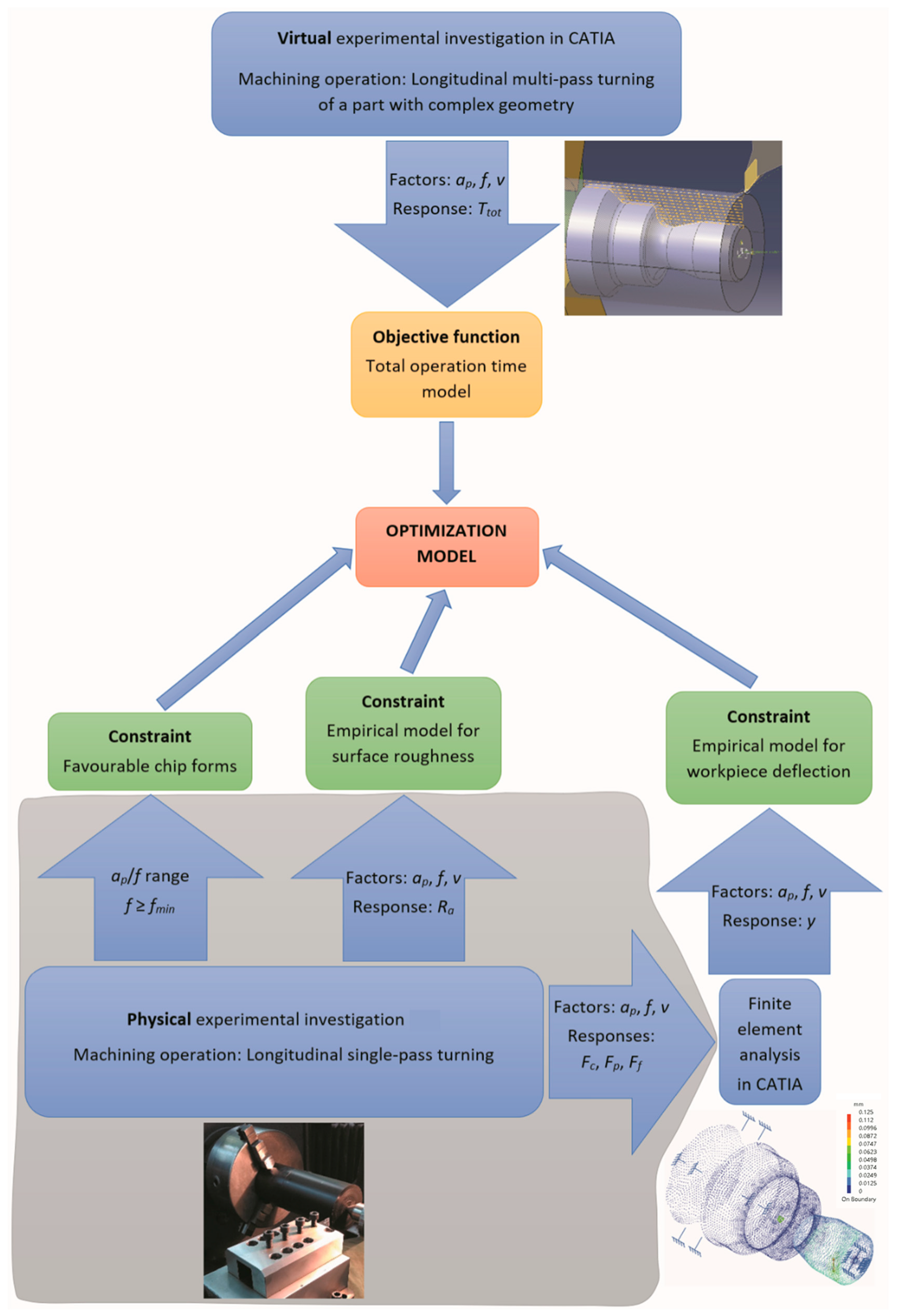
2. Materials and Methods
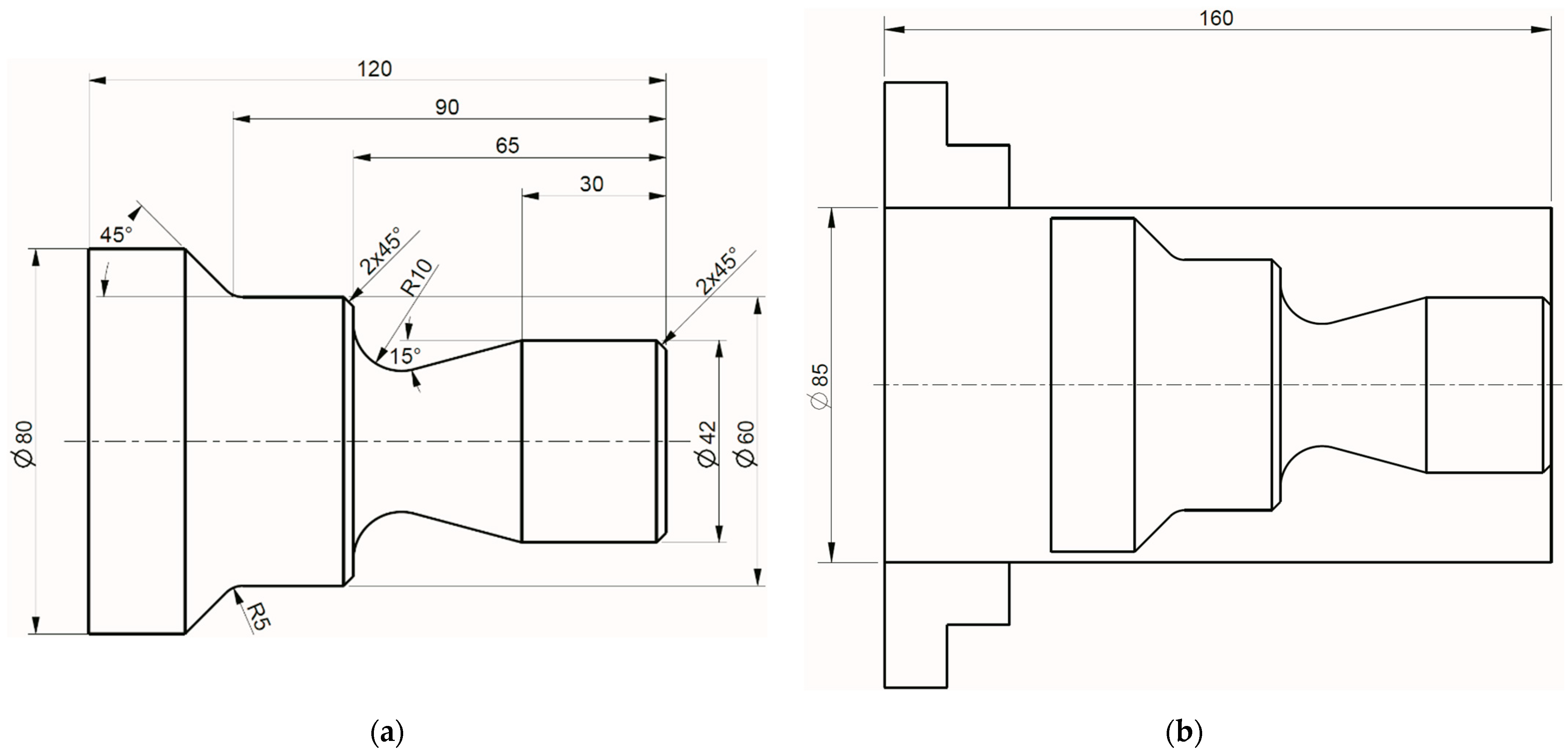
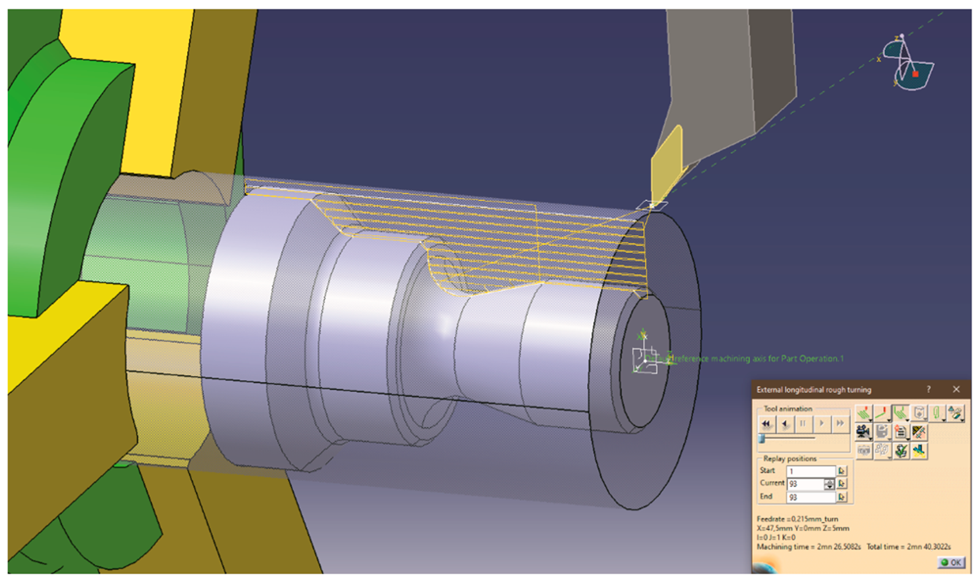
Case Study

Longitudinal multi-pass turning of a part with continuous profile, made of polyoxymethylene copolymer (POM-C), was considered as a case study to verify the proposed approach (Figure 1).
Stock is a bar with the diameter of 85 mm and the length of 160 mm made of POM-C. Material properties of POM-C are shown in Table 2. POM-C is a semicrystalline thermoplastic, widely used in food processing, agriculture, medical, electric, electronic, and automotive industries, due to good wear properties, low friction coefficient, high strength, and stiffness. It is also considered an easy machinable material.
The machine tool was the CNC lathe Gildemeister NEF 520 with the motor power of Pm = 12 kW. The spindle speed range was n = 10–3000 rpm and the maximal feed velocity was vfmax = 5000 mm/min.
The cutting tool was a toolholder Sandvik Coromant SVJBR 2020K 16 (cutting edge angle of κ = 93°), with a Walter VCGT160408FS-1 insert (rake angle of γ0i = 10°, effective cutting edge length le = 4.5 mm, nose radius rε = 0.8 mm, and grade of WDN10 (PCD)). The main advantages of the chosen positive basic shape insert with FS-1 geometry are extremely low cutting forces and extremely high surface quality [62]. Cutting insert manufacturer recommended the following cutting conditions: depth of cut of ap = 0.1–4.0 mm, feed rate of f = 0.03–0.38 mm/rev and cutting speed of v = 840–1500 m/min [62]. Cutting parameter ranges were subsequently narrowed considering machining handbooks recommendations and machining recommendations from the industrial plastic manufacturers. Since the depth of cut should be no less than the insert nose radius [63], minimal value of the depth of cut (ap) was set as 1 mm. According to the machining recommendations for POM-C from the industrial plastic manufacturers [64,65], minimal value of the feed rate (f) was set as 0.05 mm/rev, while the cutting speed (v) values were narrowed to range between 200 and 500 m/min. Final cutting conditions for the virtual experiment were: ap = 1.0–4.0 mm, f = 0.05–0.38 mm/rev and v = 200–500 m/min.
In this study, some of the results of our previous physical experimental investigation [66] were used for developing empirical models, which will be used as constraints in the formulation of the optimization problem. The study dealt with the same workpiece material (POM-C), cutting tool (VCGT160408FS-1), factors, and experimental design. This study combined experimental data from physical and virtual experiments. Figure 2 illustrates the applied research methodology for the development of single-objective turning optimization model with three constraints.
Face centred central composite design (CCD) was adopted for the virtual experimental investigation. This design is used extensively in building second-order mathematical models [67]. This design of experiments (DOE) plan represents a systematic method for creating response surface as a function of input parameters [68]. The coded and real values of the considered cutting parameters for each virtual experimental trial are given in Table 3.
For each virtual experimental trial, longitudinal multi-pass turning operation was simulated in CATIA software (V5) (Figure 3), and total time values were obtained. Total operation time is the sum of machining time and non-machining time (time needed for pre-travelling, infeed, taking off, and return) [57].
The values of cutting force components for the given cutting parameter values are required for the calculation of the displacement in specific location on the workpiece. Cutting force components were one of the responses from our previous physical experimental investigation [66], and they were used in this study. Numerical methods, as the finite element method, have gained high importance in engineering analysis, given that time and cost-intensive experimental investigations can be reduced to a minimum [69]. Finite element static structural analysis of the workpiece (finished part) was performed for each virtual experimental trial in CATIA software. Measured cutting force components for the given cutting parameter values were applied at the critical cross section of the workpiece and the maximal displacement (maximal workpiece deflection) values were obtained (Figure 4). A mesh convergence study was also performed.

3. Results and Discussion

3.1. Total Operation Time Mathematical Model

In order to define the objective function for the optimization problem, i.e., total operation time for part production, for all virtual experimental trials, tool path simulations in CATIA software were performed and the corresponding experimental values were recorded (Table 3).
The second-order polynomial model with interactions was developed initially, based on the least square method, for the prediction of the total operation time for part production. However, a graphical analysis of residuals showed that there was a nonconstant variance of residuals and few large residuals, which resulted in inadequacy of model predictions. Moreover, for certain combinations of cutting parameters, the developed model predicted negative values of total operation time for part production. In order to improve the results obtained from the quadratic mathematical model, the Box–Cox transformation approach was employed [67,70]. This approach estimated the best (optimal) lambda value of −0.36 for the transformation of the dependent variable (Ttot). The resulting prediction model, in coded form, was obtained in the following form:
T t o t 0.36 = 0.1606 0.03 · a p 0.044 · f 0.0215 · v 0.0046 · a p 2 0.00155 · f 2 0.0047 · v 2 + 0.0076 · a p · f + 0.0043 · a p · v + 0.0064 · f · v
where Ttot (s) is the total operation time for part production.
Statistics, such as predicted and adjusted coefficient of determinations, and an ANOVA analysis proved the developed model’s adequacy and statistical significance of all model terms. Moreover, a mean absolute percentage error (MAPE) between the estimated Ttot (as recorded in CATIA software) and the predicted Ttot for all tested cutting regimes was 3.53%, and is significantly lower than MAPE value of 65.12%, which was obtained prior to Box–Cox transformation of the response variable. Therefore, the derived prediction model can be used in the formulation of the optimization problem as an objective function to be minimized.

3.2. Formulation of the Machining Optimization Model

In order to determine optimal cutting regime for machining of a particular feature with respect to a given criterion and predefined process and machining constraints, the formulation and solving of a machining optimization problem is inevitable.

3.2.1. Objective Function

Given that machining companies strive to increase productivity on the machine tools they use, the estimation and analysis of production time, with respect to different alternative cutting regimes, is of utmost importance. In the present study, the mathematical model, relating cutting parameters and total operation time for part production, was selected as an objective function:
T t o t = 1 / 0.1606 0.03 · a p 0.044 · f 0.0215 · v 0.0046 · a p 2 0.00155 · f 2 0.0047 · v 2 + 0.0076 · a p · f + 0.0043 · a p · v + 0.0064 · f · v 2.778
The developed objective function is of minimization type, that is, the goal is to determine the cutting regime which would yield the lowest possible total operation time for part production.

3.2.2. Process and Machining Constraints

The specification of process and machining constraints in the formulation of a machining optimization problem is a necessary step, since for a given case study, one must consider the capabilities and technological limitations of the used machining system, imposed requirements, as well as the achievement of favourable process performances in terms of cutting mechanics.

Chip Forms and Cross-Sectional Ratio

The resulting chip form, which is obtained during machining, is dependent on the cross-sectional ratio (CSR), which is the ratio of the depth of cut and feed rate [57]. For different workpiece materials being machined, there are different ranges of CSR that result in favourable chip forms, which can be easily handled. Therefore, with respect to favourable CSRs, the following constraint may be given:
ξ m i n a p f ξ m a x
where ξmin and ξmax are the minimal and maximal CSR, whose empirical values can be found in referential literature [71]. Following empirical values for the minimal and maximal CSR for POM-C, workpiece materials were determined by Trifunović et al. [66]: ξmin = 8 and ξmax = 33, with the recommended feed rate constraint f ≥ 0.124 mm/rev (Figure 5). Chip form is one of the criteria for the evaluation of the workpiece material machinability, along with other important criteria, such as cutting force, torque, and surface roughness [72]. CSR constraint is important, given that the chip form was identified as prevalent criteria for the evaluation of POM-C machinability [66].

Surface Roughness

Surface roughness is one of the most important criteria for the assessment of the quality of the machined surface. Typically, arithmetic mean roughness (Ra) is used [1]. Its theoretical values for turning can be estimated, with respect to feed rate and tool nose radius, using the well-known analytical model. However, due to noise factors, such as built-up edge, tool wear, and chatter, significant differences between theoretical and experimental roughness values may be present [73]. Therefore, in the present research, the surface roughness constraint was based on the empirical model, in coded form, which relates the arithmetic mean roughness (Ra) from our previous physical experimental investigation [66] and cutting parameters in the following form:
R a = α 0 + α 1 · a p + α 2 · f + α 3 · v + α 11 · a p 2 + α 22 · f 2 + α 33 · v 2 + α 12 · a p · f + α 13 · a p · v + α 23 · f · v R a M A X
where Ra (μm) is the arithmetic mean roughness, and α0, α1, α2, α3, α11, α22, α33, α12, α13, and α23 are empirical constants determined by using obtained physical experimental data, and RaMAX (μm) is the maximal allowable arithmetic mean roughness (in the present study corresponding to ISO roughness grade of N6).
Estimated empirical constants of surface roughness prediction model are given in Table 4.

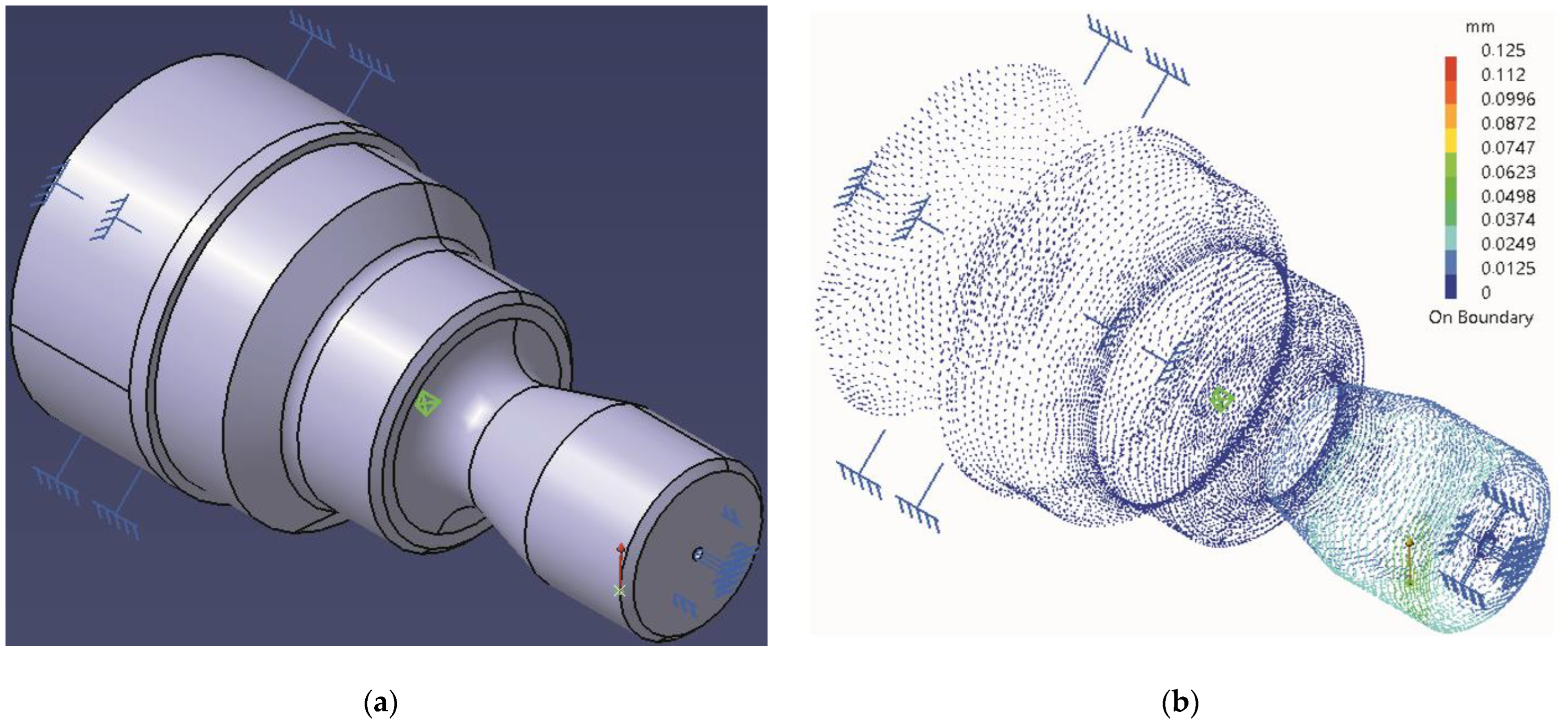
Workpiece Deflection

As argued by Benardos et al. [74], due to elastic workpiece deflections during machining, the actual depth of cut can differ from the set depth of cut, which ultimately affects the dimensional accuracy of the produced part. Since the most important quality requirement, in addition to the surface roughness, is dimensional accuracy of the produced part, the workpiece deflection during machining is considered in the present research, given that the Young’s modulus of elasticity for POM-C (E = 2900 N/mm2) is significantly lower compared to metals.
A finite element analysis of the workpiece provided a set of data, so that the following workpiece deflection model was developed:
y = β 0 + β 1 · a p + β 2 · f + β 3 · v + β 11 · a p 2 + β 22 · f 2 + β 33 · v 2 + β 12 · a p · f + β 13 · a p · v + β 23 · f · v y M A X
where y (mm) is the workpiece deflection, and β0, β1, β2, β3, β11, β22, β33, β12, β13, and β23 are empirical constants determined by performing a finite element analysis of the workpiece using obtained cutting force physical experimental data, and yMAX (mm) is the maximal allowable workpiece deflection based on dimensional tolerance or surface finish requirement. In the present study, yMAX was set at approximately 20% of the tolerance field size, as recommended by Krol [75].
Estimated empirical constants of workpiece deflection model are given in Table 4.

Other Process and Machining Constraints

Cutting force, cutting power, and torque constraints were not considered in the formulation of the present optimization problem, since turning of industrial plastics, including POM-C, does not result in high cutting forces [66] and, hence, do not violate the limitations of the used machine tool regarding maximal available torque and power on the machine tool, as well as rigidity of the machine tool. In addition, the constraint, which would specify that the minimal tool life should be at least more than the required time to finish the product, is omitted given that PCD cutting tools have much longer tool life than coated carbides, especially when machining plastic materials [76].

3.2.3. Cutting Parameter Bounds

Considering adopted cutting parameter ranges, based on insert manufacturer recommendations, machining handbooks recommendations, machining recommendations from the industrial plastic manufacturers, and validity of the developed empirical models for the covered experimental space, each cutting parameter (independent variable) is constrained with the bottom and top allowable bounds:
a p m i n a p a p m a x f m i n f f m a x v m i n v v m a x

3.3. Single-Objective Machining Optimization Problem with Constraints

The values for empirical constants, imposed requirements and constraints, valid for the present case study and experimental research, are given in Table 4.
After setting the values from Table 4, the final mathematical form of the turning optimization model can be written as:
M i n i m i z e : T t o t = 1 / 0.1606 0.03 · a p 0.044 · f 0.0215 · v 0.0046 · a p 2 0.00155 · f 2 0.0047 · v 2 + 0.0076 · a p · f + 0.0043 · a p · v + 0.0064 · f · v 2.778 S u b j e c t   t o : 8 a p f 33   chip   forms   and   cross - sec tional   ratio   constraint f 0.124 m m r e v chip   forms   and   cross - sec tional   ratio   constraint R a = 0.693 + 0.009 · a p + 0.528 · f 0.008 · v + 0.024 · a p 2 + 0.299 · f 2 + 0.0015 · v 2 + 0.012 · a p · f 0.014 · a p · v + 0.005 · f · v 0.8   surface   roughness   constraint y = 0.0427 + 0.0289 · a p + 0.0329 · f 0.0002 · v + 0.00006 · a p 2 + 0.002795 · f 2 + 0.00024 · v 2 + 0.01863 · a p · f + 0.00192 · a p · v 0.00126 · f · v 0.06   workpiece   deflection   constraint
The formulation of the developed turning optimization model, given in Equation (7), represents a single-objective optimization problem with three constraints (linear and non-linear) and three independent variables (depth of cut, cutting speed, and feed rate). With respect to the optimization problem type and complexity, and given that it represents one of the most popular methods in the field of constrained optimization [77], the sequential quadratic programming (SQP) method was applied to determine optimal solution.
Starting from the combination of low levels of all three cutting parameters, as an initial point in optimization hyper-space, the optimal combination of cutting parameter values was determined as: ap = 2.97 mm, f = 0.247 mm/rev, and v = 500 m/min. This cutting regime minimized the total operation time to Ttot = 90.5 s, and at the same time satisfied all imposed constraints. The tool path simulation in CATIA software, for the determined optimal values of cutting parameters, yielded the total operation time Ttot = 93.28 s, indicating good agreement with MAPE of about 3%. The theoretical arithmetic mean roughness value for the optimal feed rate value was Ra = 9.533 μm.
The obtained result suggests that the combination of the highest cutting speed and certain ratio of the depth of cut and feed rate represents an optimal solution. The obtained result differs from optimization studies dealing with the minimization of total production time when machining steels and cast steels [78,79], where, due to imposed cutting power and cutting force constraints, resulting optimal cutting speeds had intermediate values.
Graphical representation of the optimal cutting regime can be identified in the upper right vertex of the feasible optimization space (Figure 6). As could be observed, it is located in the intersection of maximal allowable workpiece deflection (yMAX = 0.06 mm) and maximal allowable arithmetic mean roughness (RaMAX = 0.8 μm). With respect to the determined optimal point, a further decrease in total operation time for part production by an increase in the depth of cut is restricted by the maximal allowable workpiece deflection constraint. On the other hand, a decrease in total operation time for part production by increase in the feed rate is restricted by the maximal allowable arithmetic mean roughness.
From Figure 6, one could also observe that if surface roughness constraint is relaxed, negligibly decreased total operation time for part production of Ttot = 88.19 s would be obtained with the following combination of cutting parameter values: ap = 2.49 mm, f = 0.302 mm/rev, and v = 500 m/min. However, this cutting regime would produce an arithmetic mean roughness of Ra = 1.052 μm, which is more than 25% higher compared to the arithmetic mean roughness for optimal solution.
If one considers the combination of cutting parameter values as recommended by the cutting insert manufacturer, machining handbooks, and industrial plastic manufacturers (starting values at the middle of the range) as an initial solution (ap = 2.5 mm, f = 0.215 mm/rev, and v = 350 m/min), it could be shown that all three imposed constraints would be satisfied (ap/f = 11.63, f ≥ 0.124 mm/rev, Ra = 0.693 μm and y = 0.043 mm). However, the resulting total operation time would be Ttot = 160.82 s. In accordance with these results, one can argue that determined optimal cutting regime ensures higher production rate, i.e., saving 44% of time (70.32 s) for the machining of a single part. This is significant, given that for machining of industrial plastics using PCD cutting tool the main costs rise from the labour and machine costs, and not from the cutting tool costs. Namely, as discussed in [76], PCD tools, as one of the hardest tools available, provide excellent abrasive wear resistance, and the attainable tool life may be over 1 million parts or equivalent tool life of several months without replacement in high volume production.

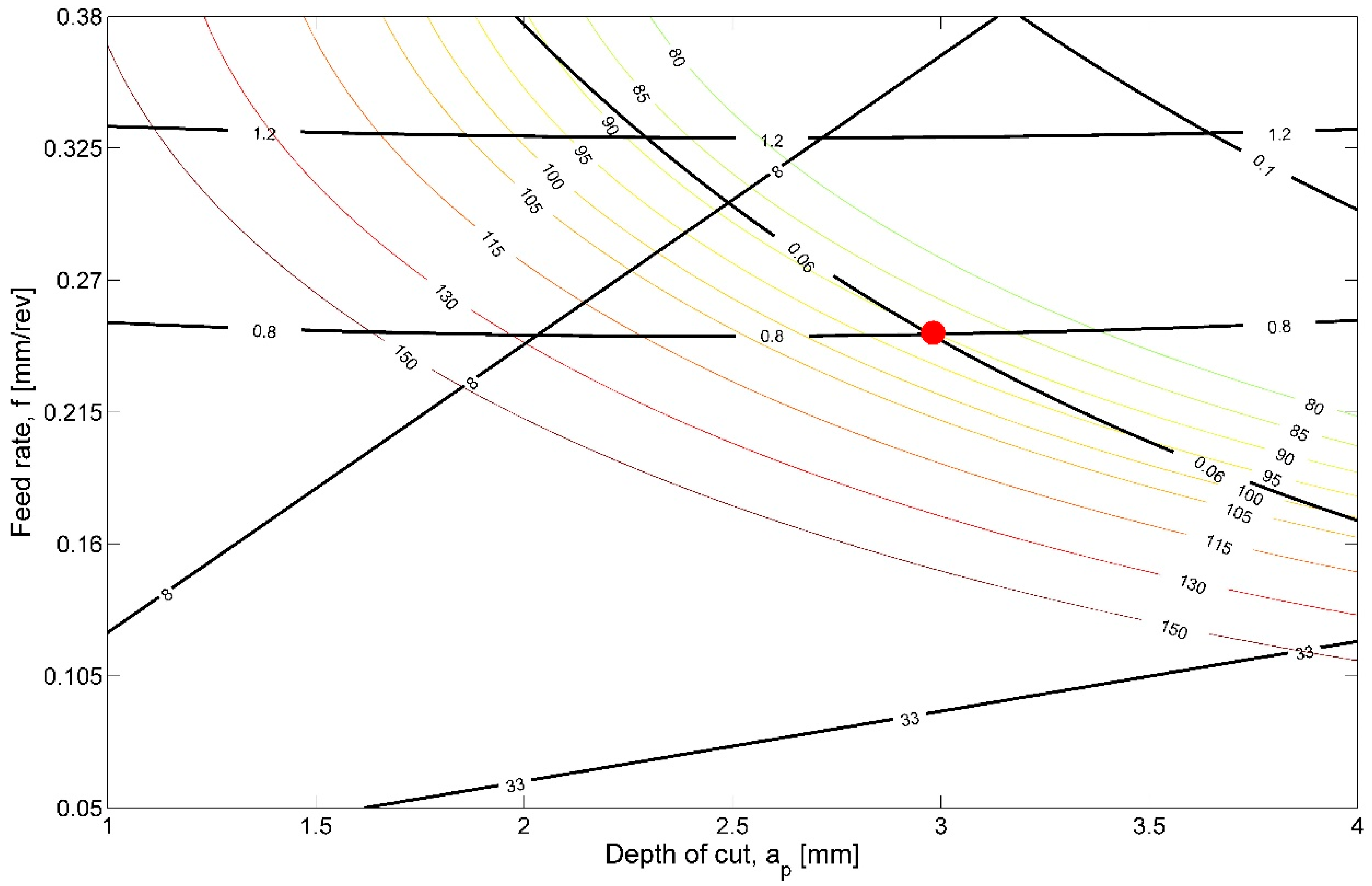
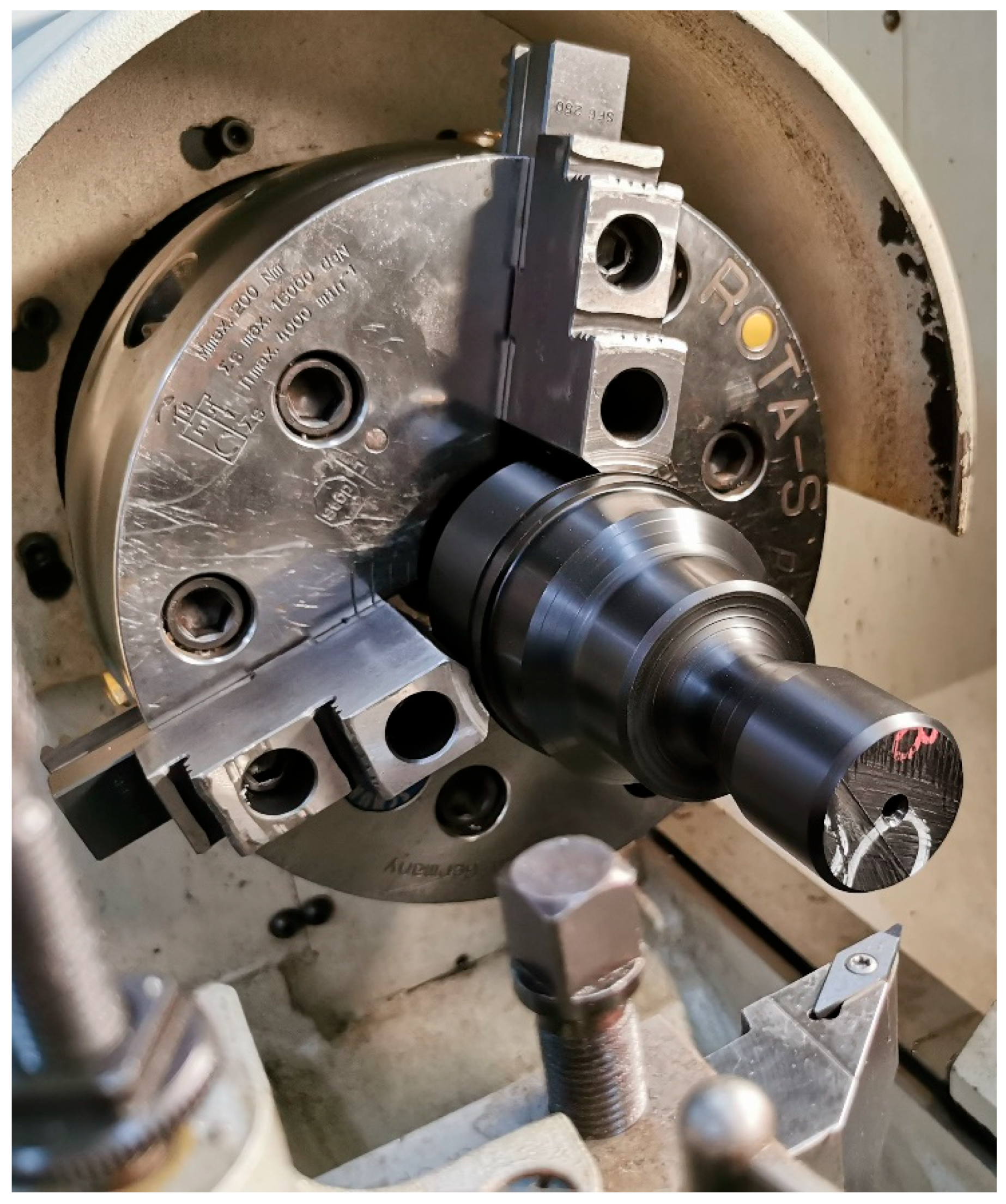
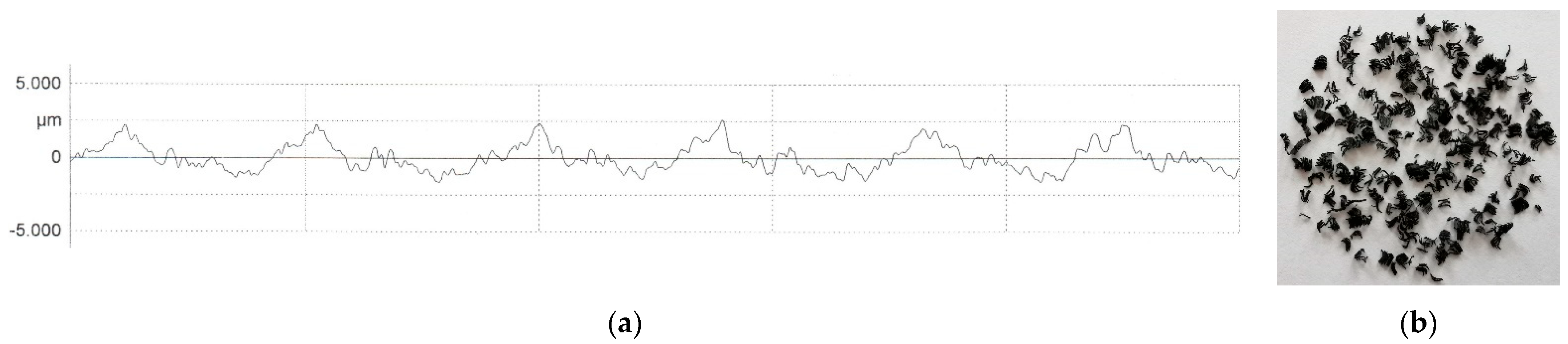
3.4. Validation Experiment Trial

In order to assess the level of consent between predictions of the developed optimization model and experimental data, the validation experiment was performed under the optimal combination of cutting parameter values, that is: ap = 2.97 mm, f = 0.247 mm/rev, and v = 500 m/min (Figure 7). During machining, the workpiece was supported by a centre mounted in the tailstock. In this way, actual machining conditions were set precisely as in the performed finite element static structural analysis of the workpiece (finished part) in CATIA software. The same machining conditions were also set in our previous study [66]. The total operation time recorded on the CNC lathe was Ttot = 90.22 s.
All three imposed constraints were satisfied for the optimization solution. The surface roughness was measured using a Mahr MarSurf XR 1 PC-based roughness measuring unit. The measured arithmetic mean value of roughness (Ra = 0.748 μm) did not violate the imposed surface roughness constraint (RaMAX = 0.8 μm). The measured maximum height of the profile was Rz = 3.785 μm. The roughness profile is shown in Figure 8a. The resulting chip form (Figure 8b), with the cross-sectional ratio of ξ = 12.02, is considered as favourable.
It has also been observed that imposition of the workpiece deflection constraint resulted in high dimensional accuracy of turned part, although low modulus of elasticity of materials tend to increase workpiece deflection and associated diameter errors [80]. Namely, at the farthest point from the chuck on the most critical diameter (D = 42 mm), the diameter value of 41.91 mm was measured, which represents a satisfactory result considering dimensional tolerance (within the permissible deviation). The obtained negative diameter error indicated overcutting during turning, which is believed to be associated with the specific properties of the used workpiece material. As observed by Islam [80], the harder the workpiece material, the less is the overcut during turning. In addition, measurements on diameters at points closer to the chuck show that as the distance from the clamping point decreases, the error on the 42 mm diameter also decreases.

4. Conclusions

The present study focused on total operation time prediction in longitudinal multi-pass turning of a part with continuous profile, made of POM-C, using a PCD cutting tool. The total operation time model was developed based on a virtual experiment, conducted in CATIA software. A single-objective optimization problem, considering total operation time as an objective function, and chip form and empirical models for surface roughness and workpiece deflection as constraints, was developed and solved. Based on the analysis of the obtained solutions, the following conclusions may be drawn:
  • The cutting parameter values recommended by the cutting insert manufacturer do not take into account the constraints. Setting constraints sets the basis for the most efficient use of the manufacturing system capabilities, primarily the capabilities of tools and machine tools, while satisfying the criteria of dimensional accuracy and quality of the machined surface.
  • The approach proposed in this paper can benefit companies that produce large series of parts with continuous profile from specific workpiece material, where the geometry of the part changes between series. In these situations, only one simple physical experimental investigation of specific workpiece material is needed to measure cutting force components and surface roughness and collect chip forms. After that, the virtual experimental investigation presented in this paper can be performed for any complex part geometry, followed by an optimization study.
  • Relaxing the surface roughness constraint results in a slightly shorter total operation time for part production, due to active workpiece deflection constraint, but also in noticeable increase in the arithmetic mean roughness, and less favourable chip form.
  • The obtained results revealed that there is a significant difference in the resulting total operation time, which would be obtained considering recommended cutting parameter values and optimized values, which justifies the optimization study.
  • An analysis of the empirical constants of prediction model for total operation time for part production showed that the feed rate has the greatest effect on the total operation time for part production, followed by the depth of cut and the cutting speed. Interaction effects involving feed rate are pronounced.
  • Defining dimensional tolerances for the turning of POM-C should be considered carefully, given possible overcutting and consequent non-conformity of machined part with respect to geometrical specifications. For the considered case study, only a fine class of general dimensional tolerances can be achieved for critical dimensions.
  • Theoretical arithmetic mean roughness value for the optimal combination of cutting parameter values is 12.74 times higher compared to the arithmetic mean roughness value measured in the validation experiment. Hence, the empirical model is much more reliable as surface roughness constraint compared to analytical one.
  • The cross-sectional ratio range, combined with the additional feed rate constraint, can be successfully used as favourable chip forms constraint. This was also proven by the results of the validation experiment. The omission of the favourable chip forms constraint in turning optimization model can lead to a situation where the optimal combination of cutting parameter values results in low surface roughness, which would be deteriorated in reality by unfavourable chip forms. The same stands for the machining time since unfavourable chip forms can lead to obstruction of the machining process and consequent machine tool shut down or idling.
  • The developed turning optimization model can serve as a benchmark optimization problem that can be solved by applying other optimization algorithms.
  • A comprehensive analysis of the influence of cutting parameters on dimensional accuracy of parts of different dimensions and geometries manufactured by turning will be in focus for the future research, since, per the authors’ knowledge, there is a limited number of recent studies on the relationship between workpiece deflection, which depends on cutting parameter values and dimensional accuracy of the finished part.
  • The development of the prediction model for the unit production time for a part with several features, where machining is performed in several different operations, will also be in focus for the future research.

Author Contributions

Conceptualization, M.M. and M.T.; methodology, M.M., M.T. and V.M.; validation, M.T. and M.M.; formal analysis, M.M., M.T. and D.M.; investigation, M.T., M.M. and D.M.; resources, M.T.; writing—original draft preparation, M.T. and M.M.; writing—review and editing, M.M., M.T., D.M. and V.M.; visualization, M.M., M.T. and V.M.; funding acquisition, D.M. All authors have read and agreed to the published version of the manuscript.

Funding

This research received no external funding.

Institutional Review Board Statement

Not applicable.

Informed Consent Statement

Not applicable.

Data Availability Statement

Not applicable.

Acknowledgments

We acknowledge support by the German Research Foundation and the Open Access Publication Fund of TU Berlin for funding this publication.

Conflicts of Interest

The authors declare no conflict of interest.

References

  1. Radovanović, M. Multi-objective optimization of multi-pass turning AISI 1064 steel. Int. J. Adv. Manuf. Technol. 2019, 100, 87–100. [Google Scholar] [CrossRef]
  2. Perec, A. Desirability Function Analysis (DFA) in Multiple Responses Optimization of Abrasive Water Jet Cutting Process. Rep. Mech. Eng. 2022, 3, 11–19. [Google Scholar] [CrossRef]
  3. Bhattacharya, S.; Chakraborty, S. Application of XGBoost algorithm as a predictive tool in a CNC turning process. Rep. Mech. Eng. 2021, 2, 190–201. [Google Scholar] [CrossRef]
  4. Sitarz, P.; Powalka, B. A new approach to improve noncircular turning process. Int. J. Adv. Manuf. Technol. 2019, 104, 3343–3360. [Google Scholar] [CrossRef]
  5. Zmarzly, P. Technological Heredity of the Turning Process. Tech. Gaz. 2020, 27, 1194–1203. [Google Scholar] [CrossRef]
  6. Khanna, N.; Shah, P.; López de Lacalle, L.N.; Rodríguez, A.; Pereira, O. In pursuit of sustainable cutting fluid strategy for machining Ti-6Al-4V using life cycle analysis. Sustain. Mater. Technol. 2021, 29, e00301. [Google Scholar] [CrossRef]
  7. Sofuoglu, M.A.; Cakir, F.H. Improving machining stability of AISI-4140 with magnetic field. Proc. Inst. Mech. Eng. C J. Mech. Eng. Sci. 2022, 236, 6095–6102. [Google Scholar] [CrossRef]
  8. Agrawal, C.; Wadhwa, J.; Pitroda, A.; Pruncu, C.I.; Sarikaya, M.; Khanna, N. Comprehensive analysis of tool wear, tool life, surface roughness, costing and carbon emissions in turning Ti–6Al–4V titanium alloy: Cryogenic versus wet machining. Tribol. Int. 2021, 153, 106597. [Google Scholar] [CrossRef]
  9. Suárez, A.; Veiga, F.; López de Lacalle, L.N.; Polvorosa, R.; Wretland, A. An investigation of cutting forces and tool wear in turning of Haynes 282. J. Manuf. Process. 2019, 37, 529–540. [Google Scholar] [CrossRef]
  10. Das, A.; Gupta, M.K.; Das, S.R.; Panda, A.; Patel, S.K.; Padhan, S. Hard turning of AISI D6 steel with recently developed HSN2-TiAlxN and conventional TiCN coated carbide tools: Comparative machinability investigation and sustainability assessment. J. Braz. Soc. Mech. Sci. Eng. 2022, 44, 138. [Google Scholar] [CrossRef]
  11. Storchak, M.; Drewle, K.; Menze, C.; Stehle, T.; Mohring, H.C. Determination of the Tool–Chip Contact Length for the Cutting Processes. Materials 2022, 15, 3264. [Google Scholar] [CrossRef] [PubMed]
  12. Fernández-Valdivielso, A.; López de Lacalle, L.N.; Urbikain, G.; Rodriguez, A. Detecting the key geometrical features and grades of carbide inserts for the turning of nickel-based alloys concerning surface integrity. Proc. Inst. Mech. Eng. C J. Mech. Eng. Sci. 2016, 230, 3725–3742. [Google Scholar] [CrossRef]
  13. Mallick, R.; Kumar, R.; Panda, A.; Sahoo, A.K. Hard turning performance evaluation using CVD and PVD coated carbide tools: A comparative study. Surf. Rev. Lett. 2022, 29, 2250020. [Google Scholar] [CrossRef]
  14. Khanna, N.; Shah, P.; Sarikaya, M.; Pusavec, F. Energy consumption and ecological analysis of sustainable and conventional cutting fluid strategies in machining 15–5 PHSS. Sustain. Mater. Technol. 2022, 32, e00416. [Google Scholar] [CrossRef]
  15. Mia, M.; Gupta, M.K.; Singh, G.; Krolczyk, G.; Pimenov, D.Y. An approach to cleaner production for machining hardened steel using different cooling-lubrication conditions. J. Clean. Prod. 2018, 187, 1069–1081. [Google Scholar] [CrossRef]
  16. Magalhães, L.C.; Carlesso, G.C.; López de Lacalle, L.N.; Souza, M.T.; de Oliveira Palheta, F.; Binder, C. Tool Wear Effect on Surface Integrity in AISI 1045 Steel Dry Turning. Materials 2022, 15, 2031. [Google Scholar] [CrossRef] [PubMed]
  17. Kim, D.M.; Kim, H.I.; Park, H.W. Tool wear, economic costs, and CO2 emissions analysis in cryogenic assisted hard-turning process of AISI 52100 steel. Sustain. Mater. Technol. 2021, 30, e00349. [Google Scholar] [CrossRef]
  18. Rahman, M.A.; Bhuiyan, M.S.; Sharma, S.; Kamal, M.S.; Imtiaz, M.M.M.; Alfaify, A.; Nguyen, T.T.; Khanna, N.; Sharma, S.; Gupta, M.K.; et al. Influence of Feed Rate Response (FRR) on Chip Formation in Micro and Macro Machining of Al Alloy. Metals 2021, 11, 159. [Google Scholar] [CrossRef]
  19. Ranjan, P.; Hiremath, S.S. Investigation of Coated Tool Performance on the Machinability, Surface Residual Stress and Chip Morphology of Martensitic AISI 420 Steel. Arab. J. Sci. Eng. 2022, 47, 8503–8522. [Google Scholar] [CrossRef]
  20. Pereira, O.; Rodríguez, A.; Fernández-Abia, A.I.; Barreiro, J.; López de Lacalle, L.N. Cryogenic and minimum quantity lubrication for an eco-efficiency turning of AISI 304. J. Clean. Prod. 2016, 139, 440–449. [Google Scholar] [CrossRef]
  21. Uysal, A.; Jawahir, I.S. Analysis of slip-line model for serrated chip formation in orthogonal machining of AISI 304 stainless steel under various cooling/lubricating conditions. J. Manuf. Process. 2021, 67, 447–460. [Google Scholar] [CrossRef]
  22. Kuruc, M.; Vopat, T.; Peterka, J.; Necpal, M.; Šimna, V.; Milde, J.; Jurina, F. The Influence of Cutting Parameters on Plastic Deformation and Chip Compression during the Turning of C45 Medium Carbon Steel and 62SiMnCr4 Tool Steel. Materials 2022, 15, 585. [Google Scholar] [CrossRef] [PubMed]
  23. Leksycki, K.; Feldshtein, E.; Ociepa, M. On the effect of the side flow of 316L stainless steel in the finish turning process under dry conditions. Facta Univ. Ser. Mech. Eng. 2021, 19, 335–343. [Google Scholar] [CrossRef]
  24. Suárez, A.; López de Lacalle, L.N.; Polvorosa, R.; Veiga, F.; Wretland, A. Effects of high-pressure cooling on the wear patterns on turning inserts used on alloy IN718. Mater. Manuf. Process. 2017, 32, 678–686. [Google Scholar] [CrossRef]
  25. Tan, L.; Yao, C.; Li, X.; Fan, Y.; Cui, M. Effects of Machining Parameters on Surface Integrity when Turning Inconel 718. J. Mater. Eng. Perform. 2022, 31, 4176–4186. [Google Scholar] [CrossRef]
  26. Fernando, R.; Gamage, J.; Karunathilake, H. Sustainable machining: Environmental performance analysis of turning. Int. J. Sustain. Eng. 2022, 15, 15–34. [Google Scholar] [CrossRef]
  27. Branco, F.K.; Delijaicov, S.; Bordinassi, E.C.; Bortolussi, R. Surface Integrity Analisys in the Hard Turning of Cemented Steel AISI 4317. Mater. Res. 2018, 21, e20171032. [Google Scholar] [CrossRef]
  28. Arora, D.; Duvedi, R.K.; Singh, D. Effect of Machining Parameters on Surface Finish and Noise Patterns for Machining EN-19 Steel with PVD-TiN Coated Mixed Ceramic Inserts in CNC Turning Operation. J. Sci. Ind. Res. 2020, 79, 235–240. [Google Scholar]
  29. Tzotzis, A.; Garcia-Hernandez, C.; Huertas-Talon, J.L.; Kyratsis, P. 3D FE Modelling of Machining Forces during AISI 4140 Hard Turning. Stroj. Vestn.-J. Mech. Eng. 2020, 66, 467–478. [Google Scholar] [CrossRef]
  30. Abdelnasser, E.; Barakat, A.; Elsanabary, S.; Nassef, A.; Elkaseer, A. Precision Hard Turning of Ti6Al4V Using Polycrystalline Diamond Inserts: Surface Quality, Cutting Temperature and Productivity in Conventional and High-Speed Machining. Materials 2020, 13, 5677. [Google Scholar] [CrossRef]
  31. Palaniappan, T.; Subramaniam, P. Experimental Investigation and Prediction of Mild Steel Turning Performances Using Hybrid Deep Convolutional Neural Network-Based Manta-Ray Foraging Optimizer. J. Mater. Eng. Perform. 2022, 31, 4848–4863. [Google Scholar] [CrossRef]
  32. Cica, D.; Kramar, D. Machinability investigation and sustainability analysis of high-pressure coolant assisted turning of the nickel-based superalloy Inconel 718. Proc. Inst. Mech. Eng. B J. Eng. Manuf. 2022, 237, 43–54. [Google Scholar] [CrossRef]
  33. Bhandarkar, L.R.; Mohanty, P.P.; Sarangi, S.K. Experimental study and multi-objective optimization of process parameters during turning of 100Cr6 using C-type advanced coated tools. Proc. Inst. Mech. Eng. C J. Mech. Eng. Sci. 2021, 235, 7634–7654. [Google Scholar] [CrossRef]
  34. Chen, S.H.; Hsu, C.H. Using uniform design and regression methodology of turning parameters study of nickel alloy. Int. J. Adv. Manuf. Technol. 2021, 116, 3795–3808. [Google Scholar] [CrossRef]
  35. Rafighi, M. The cutting sound effect on the power consumption, surface roughness, and machining force in dry turning of Ti-6Al-4V titanium alloy. Proc. Inst. Mech. Eng. C J. Mech. Eng. Sci. 2022, 236, 3041–3057. [Google Scholar] [CrossRef]
  36. Khan, A.M.; Anwar, S.; Jamil, M.; Nasr, M.M.; Gupta, M.K.; Saleh, M.; Ahmad, S.; Mia, M. Energy, Environmental, Economic, and Technological Analysis of Al-GnP Nanofluid- and Cryogenic LN2-Assisted Sustainable Machining of Ti-6Al-4V Alloy. Metals 2021, 11, 88. [Google Scholar] [CrossRef]
  37. Sterpin Valic, G.; Cukor, G.; Jurkovic, Z.; Brezocnik, M. Multi-Criteria Optimization of Turning of Martensitic Stainless Steel for Sustainability. Int. J. Simul. Model. 2019, 18, 632–642. [Google Scholar] [CrossRef] [PubMed]
  38. Hadjela, S.; Belhadi, S.; Ouelaa, N.; Safi, K.; Yallese, M.A. Straight turning optimization of low alloy steel using MCDM methods coupled with Taguchi approach. Int. J. Adv. Manuf. Technol. 2022, 124, 1607–1621. [Google Scholar] [CrossRef]
  39. Palacios, J.A.; Olvera, D.; Urbikain, G.; Elías-Zúñiga, A.; Martínez-Romero, O.; López de Lacalle, L.N.; Rodríguez, C.; Martínez-Alfaro, H. Combination of simulated annealing and pseudo spectral methods for the optimum removal rate in turning operations of nickel-based alloys. Adv. Eng. Softw. 2018, 115, 391–397. [Google Scholar] [CrossRef]
  40. Dragičević, M.; Begović, E.; Ekinović, S.; Peko, I. Multi-Response Optimization in MQLC Machining Process of Steel St50-2 Using Grey-Fuzzy Technique. Tech. Gaz. 2023, 30, 248–255. [Google Scholar] [CrossRef]
  41. Armillotta, A. On the role of complexity in machining time estimation. J. Intell. Manuf. 2021, 32, 2281–2299. [Google Scholar] [CrossRef]
  42. Rodrigues, A.; Silva, F.J.G.; Sousa, V.F.C.; Pinto, A.G.; Ferreira, L.P.; Pereira, T. Using an Artificial Neural Network Approach to Predict Machining Time. Metals 2022, 12, 1709. [Google Scholar] [CrossRef]
  43. Parmar, J.G.; Dave, K.G.; Gohil, A.V.; Trivedi, H.S. Prediction of end milling process parameters using artificial neural network. Mater. Today Proc. 2021, 38, 3168–3176. [Google Scholar] [CrossRef]
  44. Sousa, V.F.C.; Silva, F.J.G. Recent Advances in Turning Processes Using Coated Tools—A Comprehensive Review. Metals 2020, 10, 170. [Google Scholar] [CrossRef]
  45. Chinchanikar, S.; Choudhury, S.K. Machining of hardened steel—Experimental investigations, performance modeling and cooling techniques: A review. Int. J. Mach. Tools Manuf. 2015, 89, 95–109. [Google Scholar] [CrossRef]
  46. Pimenov, D.Y.; Bustillo, A.; Wojciechowski, S.; Sharma, V.S.; Gupta, M.K.; Kuntoglu, M. Artificial intelligence systems for tool condition monitoring in machining: Analysis and critical review. J. Intell. Manuf. 2022, 1–43. [Google Scholar] [CrossRef]
  47. Sen, B.; Mia, M.; Krolczyk, G.M.; Mandal, U.K.; Mondal, S.P. Eco-Friendly Cutting Fluids in Minimum Quantity Lubrication Assisted Machining: A Review on the Perception of Sustainable Manufacturing. Int. J. Precis. Eng. Manuf. Green Technol. 2021, 8, 249–280. [Google Scholar] [CrossRef]
  48. Krolczyk, G.M.; Maruda, R.W.; Krolczyk, J.B.; Wojciechowski, S.; Mia, M.; Nieslony, P.; Budzik, G. Ecological trends in machining as a key factor in sustainable production—A review. J. Clean. Prod. 2019, 218, 601–615. [Google Scholar] [CrossRef]
  49. Benedicto, E.; Carou, D.; Rubio, E.M. Technical, Economic and Environmental Review of the Lubrication/Cooling Systems used in Machining Processes. Procedia Eng. 2017, 184, 99–116. [Google Scholar] [CrossRef]
  50. Goindi, G.S.; Sarkar, P. Dry machining: A step towards sustainable machining—Challenges and future directions. J. Clean. Prod. 2017, 165, 1557–1571. [Google Scholar] [CrossRef]
  51. Gupta, K.; Laubscher, R.F. Sustainable machining of titanium alloys: A critical review. Proc. Inst. Mech. Eng. B J. Eng. Manuf. 2017, 231, 2543–2560. [Google Scholar] [CrossRef]
  52. Zhao, G.Y.; Liu, Z.Y.; He, Y.; Cao, H.J.; Guo, Y.B. Energy consumption in machining: Classification, prediction, and reduction strategy. Energy 2017, 133, 142–157. [Google Scholar] [CrossRef]
  53. Urbikain, G.; Olvera, D.; López de Lacalle, L.N.; Beranoagirre, A.; Elías-Zuñiga, A. Prediction Methods and Experimental Techniques for Chatter Avoidance in Turning Systems: A Review. Appl. Sci. 2019, 9, 4718. [Google Scholar] [CrossRef]
  54. Trifunović, M.; Madić, M.; Radovanović, M. Pareto optimization of multi-pass turning of grey cast iron with practical constraints using a deterministic approach. Int. J. Adv. Manuf. Technol. 2020, 110, 1893–1909. [Google Scholar] [CrossRef]
  55. Thorenz, B.; Oßwald, F.; Schotz, S.; Westermann, H.H.; Dopper, F. Applying and Producing Indexable End Mills: A Comparative Market Study in Context of Resource Efficiency. Procedia Manuf. 2020, 43, 167–174. [Google Scholar] [CrossRef]
  56. Westermann, H.H.; Kafara, M.; Steinhilper, R. Development of a reference part for the evaluation of energy efficiency in milling operations. Procedia CIRP 2015, 26, 521–526. [Google Scholar] [CrossRef]
  57. Tschatsch, H. Applied Machining Technology; Springer Science & Business Media: New York, NY, USA, 2009; pp. 34, 70–72. [Google Scholar]
  58. Chung, C.; Wang, P.C.; Chinomona, B. Optimization of turning parameters based on tool wear and machining cost for various parts. Int. J. Adv. Manuf. Technol. 2022, 120, 5163–5174. [Google Scholar] [CrossRef]
  59. Silva, F.J.G.; Sousa, V.F.C.; Pinto, A.G.; Ferreira, L.P.; Pereira, T. Build-Up an Economical Tool for Machining Operations Cost Estimation. Metals 2022, 12, 1205. [Google Scholar] [CrossRef]
  60. Madić, M.; Gostimirović, M.; Rodić, D.; Radovanović, M.; Coteata, M. Mathematical modelling of the CO2 laser cutting process using genetic programming. Facta Univ. Ser. Mech. Eng. 2022, 20, 665–676. [Google Scholar] [CrossRef]
  61. Jeang, A. Robust cutting parameters optimization for production time via computer experiment. Appl. Math. Model. 2011, 35, 1354–1362. [Google Scholar] [CrossRef]
  62. Walter. General Catalogue; Walter AG: Tübingen, Germany, 2017. [Google Scholar]
  63. Sandvik, C. Metal Cutting Technology Training Handbook; SANDVIK Coromant: Stockholm, Sweden, 2017. [Google Scholar]
  64. Dotmar. Machining Instructions. 2013. Available online: http://www.dotmar.com.au/images/machining_instructions.pdf (accessed on 20 January 2023).
  65. Mitsubishi Chemical Advanced Materials. Machining Instructions. 2014. Available online: https://media.mcam.com/fileadmin/quadrant/documents/QEPP/EU/Brochures_PDF/Machining_instructions_Quadrant_EPP_version_2014.pdf (accessed on 20 January 2023).
  66. Trifunović, M.; Madić, M.; Janković, P.; Rodić, D.; Gostimirović, M. Investigation of cutting and specific cutting energy in turning of POM-C using a PCD tool: Analysis and some optimization aspects. J. Clean. Prod. 2021, 303, 127043. [Google Scholar] [CrossRef]
  67. Montgomery, D.C. Design and Analysis of Experiments, 9th ed.; John Wiley & Sons: Hoboken, NJ, USA, 2017; pp. 288, 657–659. [Google Scholar]
  68. Hassanzadeh, M.; Moussavi Torshizi, S.E. Multi-objective Optimization of Shot-peening Parameters using Design of Experiments and Finite Element Simulation: A Statistical Model. J. Appl. Comput. Mech. 2022, 8, 838–852. [Google Scholar] [CrossRef]
  69. Strzalka, C.; Marinkovic, D.; Zehn, M.W. Stress Mode Superposition for a Priori Detection of Highly Stressed Areas: Mode Normalisation and Loading Influence. J. Appl. Comput. Mech. 2021, 7, 1698–1709. [Google Scholar] [CrossRef]
  70. Osborne, J.W. Improving your data transformations: Applying the Box-Cox transformation. Pract. Assess. Res. Eval. 2010, 15, 12. [Google Scholar] [CrossRef]
  71. Kopač, J. Odrezavanje; Fakulteta za strojništvo: Ljubljana, Slovenija, 1991. [Google Scholar]
  72. Stanojković, J.; Radovanović, M. Influence of the cutting parameters on force, moment and surface roughness in the end milling of aluminum 6082-T6. Facta Univ. Ser. Mech. Eng. 2022, 20, 157–165. [Google Scholar] [CrossRef]
  73. Madić, M.; Trifunović, M.; Janković, T. Development and analysis of a surface roughness model in dry straight turning of C45E steel. Innov. Mech. Eng. 2022, 1, 11–21. [Google Scholar]
  74. Benardos, P.G.; Mosialos, S.; Vosniakos, G.C. Prediction of workpiece elastic deflections under cutting forces in turning. Robot. Comput. Integr. Manuf. 2006, 22, 505–514. [Google Scholar] [CrossRef]
  75. Krol, O. Metal Cutting in Tasks for Machine Tool Designers; Prof. Marin Drinov Academic Publishing House of Bulgarian Academy of Sciences: Sofia, Bulgaria, 2022; p. 62. [Google Scholar]
  76. Stephenson, D.A.; Agapiou, J.S. Metal Cutting Theory and Practice, 3rd ed.; CRC Press: Boca Raton, FL, USA, 2016; p. 547. [Google Scholar]
  77. Arora, R.K. Optimization: Algorithms and Applications; CRC Press: Boca Raton, FL, USA, 2015; p. 176. [Google Scholar]
  78. Shin, Y.C.; Joo, Y.S. Optimization of machining conditions with practical constraints. Int. J. Prod. Res. 1992, 30, 2907–2919. [Google Scholar] [CrossRef]
  79. Agapiou, J.S. The Optimization of Machining Operations Based on a Combined Criterion, Part 1: The Use of Combined Objectives in Single-Pass Operations. J. Manuf. Sci. Eng. 1992, 114, 500–507. [Google Scholar] [CrossRef]
  80. Islam, M.N. Effect of additional factors on dimensional accuracy and surface finish of turned parts. Mach. Sci. Technol. 2013, 17, 145–162. [Google Scholar] [CrossRef]
Figure 1. Technical drawing of the finished part (a) and stock (b).
Metals 13 00359 g001
Figure 2. Flowchart of the research methodology used for the case study. Gray background indicates results from previous physical experimental investigation that were used.
Metals 13 00359 g002
Figure 3. Tool path simulation in CATIA software with results.
Metals 13 00359 g003
Figure 4. Workpiece deflection analysis: CAD model with boundary conditions (a) and displacements computed by means of FE models (b).
Metals 13 00359 g004
Figure 5. Chip forms obtained for different values of the depth of cut and the feed rate, when turning POM-C with a PCD cutting tool. Values in purple indicate the cross-sectional ratio. Favourable chip forms are framed by green lines.
Metals 13 00359 g005
Figure 6. Graphical representation of the determined optimal solution (overlaid contour diagram).
Metals 13 00359 g006
Figure 7. Finished part within the CNC lathe.
Metals 13 00359 g007
Figure 8. Roughness profile obtained under optimized cutting conditions (a). Resulting chip form obtained under optimized cutting conditions (b).
Metals 13 00359 g008
Table 1. Overview of recent research aspects in turning.
AspectExperimental and Theoretical Considerations Modelling and Optimization
Chip formation
Chip forms[7,9,10,15,18,19]
Chip thickness[21][31]
Tool-chip contact length[11][32]
Chip reduction coefficient [33]
Chip compression[22]
Plastic deformation[22]
Side flow[23]
Machining mechanics (cutting forces)[6,9,10,12,19,20,21,24][27,29,31,32,33,34,35,40]
Machining stability (vibration amplitude and other vibrational parameters)[7][39]
Noise level [28]
Cutting temperature[7,10,15][30]
Environmental performance
Energy consumption[14][26,36]
Power consumption[8][35,36]
Cutting fluid consumption [26]
Tool wear[6,8,9,10,12,13,15,16,17,19,20,24][31,32,34,38]
Tool life[13,17][32,37]
Machining economics
Machining cost[8,10,17][32,36]
Machining time[41][34,42,43]
Surface integrity
Residual stresses[12,19,25][27]
White layer [27]
Microhardness and microstructure[12,16,20,25]
Surface texture[13]
Surface defect[19]
Quality of the machined surface
Surface roughness[5,6,7,8,9,10,12,13,15,16][25,26,27,28,30,31,33,34,35,37,38,40]
Roundness and cylindricity of the machined surface[5]
Productivity (material removal rate) [26,30,32,37,38,39]
Sustainability
Carbon emissions[8,17][32,36]
Life cycle assessment[14]
Process efficiency[4]
Table 2. Properties of POM-C.
PropertyValue
Yield stress (N/mm2)65
Modulus of elasticity in tension (N/mm2)2900
Shore D Hardness81
Poisson ratio0.43
Thermal coefficient of linear expansion (K−1·10−5)11
Mass density (g/cm3)1.41
Table 3. Face centred CCD design for virtual experimental trials and resulting total operation time.
Experimental
Trial
Coded ValuesReal ValuesTotal
Operation Time
apfvap (mm)f (mm/rev)v (m/min)Ttot (s)
1−1−1−11.00.0502002457.44
21−1−14.00.050200663.38
3−11−11.00.380200359.03
411−14.00.380200112.25
5−1−111.00.0505001018.52
61−114.00.050500277.56
7−1111.00.380500150.89
81114.00.38050048.00
9−1001.00.215350346.20
101004.00.215350101.34
110−102.50.050350628.24
120102.50.38035098.73
1300−12.50.215200279.11
140012.50.215500117.84
150002.50.215350160.30
160002.50.215350160.30
170002.50.215350160.30
Table 4. Turning optimization model data.
ParameterValueParameterValueParameterValue
ξmin8 α220.299β3−0.0002
ξmax33α330.0015β110.00006
RaMAX0.8 μmα120.012β220.002795
α00.693α13−0.014β330.00024
α10.009α230.005β120.01863
α20.528β00.0427β130.00192
α3−0.008β10.0289β23−0.00126
α110.024β20.0329yMAX0.06 mm
apmin1 mmfmin0.05 mm/revvmin200 m/min
apmax4 mmfmax0.38 mm/revvmax500 m/min
Disclaimer/Publisher’s Note: The statements, opinions and data contained in all publications are solely those of the individual author(s) and contributor(s) and not of MDPI and/or the editor(s). MDPI and/or the editor(s) disclaim responsibility for any injury to people or property resulting from any ideas, methods, instructions or products referred to in the content.

