Article

Strength Analysis of Eight-Wheel Bogie of Bucket Wheel Excavator

1
Institute of Information Technologies, University of Kragujevac, 34 000 Kragujevac, Serbia
2
Faculty of Engineering, University of Kragujevac, 34000 Kragujevac, Serbia
3
Department of Industrial Engineering, University of Bologna, 40136 Bologna, Italy
*
Authors to whom correspondence should be addressed.
Metals 2023, 13(3), 466; https://doi.org/10.3390/met13030466
Submission received: 16 January 2023 / Revised: 13 February 2023 / Accepted: 20 February 2023 / Published: 23 February 2023

Abstract

:
Crawler travel gear is a type of heavy vehicle propulsion that is commonly found in tanks, excavators, and specialized off-road vehicles. They have an advantage over wheels when it comes to robust vehicle weight distribution over soft terrain, and some disadvantages as well. They can damage paved roads and have complex design so, considering the enormous weight they must carry, their reliability must be determined and verified. The main parts of the assembly are the drive wheels, which move the crawler, and the supporting structure that holds four-wheel bogies and two-wheel bogies. In this paper, we present a methodology for FEM analysis of parts of an eight-wheel bogie according to DIN 22261-2 standard.

1. Introduction

The operation fuel of thermal power plants in Serbia is lignite [1]. Lignite production is carried out in open-pit mines. Spreaders, bucket wheel excavators (BWEs), etc., are a group of heavy machines commonly used in the mining, power, and bulk-handling industries. The primary application of BWEs is in lignite mining. Due to the great demand for lignite, lignite mining has also been one of the areas of greatest development for BWEs. The additions of automated systems and greater maneuverability, as well as components designed for specific applications, have increased the reliability and efficiency of BWEs [2]. Bucket wheel excavators are one of the largest and heaviest machines in the world that are used for large-scale mining operations. The Guinness World Record for the tallest land vehicle is shared by Bagger 293 with Bagger 288. Bagger 293 is 96 m high, 225 m long (same as Bagger 287), weighs 14,200 tons, and requires five people to operate it [2]. BWEs are designed for many years of operation. In Serbia, 32 BWEs are in operation in surface coal mines [3].
There is a difference in design for BWEs and depending on block width, cutting height, and site conditions, a difference is made between compact and large bucket wheel excavators. Design and testing of specialized mining and material handling equipment requires a lot of knowledge and experience due to the many applicable standards available. The literature in [4] presents and compares the theoretical assumptions stated in the three standards DIN 22261, ISO 5049, and AS 4324. The construction of the BWEs consists of a superstructure to which several other components are attached: the bucket wheel with drive, bucket wheel conveyor, pylon structure, maintenance crane, center chute, operation cabin, crawler travel gear, counterweight boom, and slewing platform. The bucket wheel from which the machines obtain their name is a large, round wheel with a configuration of scoops that is fixed to a boom and is capable of rotating. Material picked up by the cutting wheel is transferred back along the boom. A discharge boom receives material through the superstructure from the cutting boom and carries it away from the machine, frequently to an external conveyor system. A counterweight boom balances the cutting boom and is cantilevered either on the lower part of the superstructure (in the case of compact BWEs) or the upper part (in the case of mid-size C-frame BWEs). To allow it to complete its duties, the superstructure of a BWE is capable of rotating about a vertical axis (slewing). The cutting boom can be tilted up and down (hoisting). Slewing is driven by large gears, while hoisting generally makes use of a cable system. Identification of its basic parameters of static stability (BPSS: weight and position of the center of gravity) is of equally crucial significance in design of a BWE and in its exploitation [5]. The main part of the construction of the bucket wheel excavator (BWE) is the slewing platform. The occurrence and propagation of cracks in the zones of the slewing platform shell can probably lead to the collapse of the BWE. In the paper in [6], the authors investigated the causes of crack occurrence in the zone of the slewing platform mantle holes, reconstructed the design of the mantle, and verified the reconstructed structure by numerical–experimental analysis. For machines such as excavators, large-sized thrust ball bearings of extremely large size and capacity are common applied. This kind of thrust bearing can perform both slewing movements as well as rotational movements, and because of that, “slewing bearing” is their common name. In the paper in [7], research into the possible causes of failures of thrust ball bearings in BWE is presented.
There is research concerning damage and breakdowns of the parts of bucket wheel excavators (BWE). Most components and elements of vital structures of bucket wheel excavators are exposed to a significantly strong effect of dynamic loads, which depend on conditions of exploitation (resistance to digging and own oscillations). Continuous exploitation in difficult working conditions leads to the appearance of plastic deformations and fatigue cracks. Propagation fatigue crack in the vital parts of the support structure, such as tie-rods (of the bucket wheel boom [8,9], counterweight arm or portal [10]) and their supports can lead to breaks in vital parts [11,12,13,14,15,16,17,18,19,20]. After a part breaks, it is necessary to find the cause of the break, make repairs, and assess the remaining life of the structure [8,10,13,14,15]. Based on the presented results in the paper in [8], it is clear that the support failure was a consequence of the superposition of negative effects caused by inadequate shaping and dimensioning of the supporting assembly for the given load conditions. The paper in [13] examines the causes of bucket wheel axle fractures. The numerical analysis of the bucket wheel axle shows that the negative influences of support of the axle reflect through the increase in the stress concentration and the occurrence of the initial crack are the main causes of the axle fracture.
Through the life cycle of the BWE, periodic checks of the responsible parts of the structure are carried out, after which an assessment of the remaining life of the structure is required [9,11,12]. The paper in [9] presents the determination of the remaining fatigue life of the bucket wheel based on the stress–state characteristics in the welded joint defined by experimental research in real working conditions. A methodological approach for the assessment of the service life of vital welded structures of a bucket wheel excavator boom was presented in the papers [11,12].
Under the superstructure lays the movement systems. Newer BWEs are frequently equipped with crawlers, which grant them increased flexibility of motion. Failures of crawler travel gear parts (drive shaft [21,22], crawler chain link [23], chassis [24], two-wheel bogie [25,26]) are always followed by high financial losses and replacements of damaged parts are executed on site, often in hard working conditions. The drive shaft fracture of the bucket wheel excavator is analyzed in paper [21]. In this BWE, the drive shaft fracture occurs at the point of support on the penetration side. The goal of the study presented in paper [23] was to diagnose the cause of the damage of the bucket wheel excavator crawler chain links. Based on the results of the numerical experimental analyses, it was concluded that the chain link failures are predominantly caused by so-called ‘manufacturing-in’ defects. The investigation into the reasons of the TWB structure failure and its redesign is given in [25,26]. The results of finite element analysis of two-wheel (TWB), four-wheel (FWB), and eight-wheel (EWB) bogies given in [27] identified weak points in the equalizing system (ES) structure. Finite element method (FEM) simulations [28,29] are widely used for solving various problems in the heavy machinery industry because they can determine the condition of parts and assemblies without damaging or destroying them. FEM results provide very useful information about the significant loading zones in the analyzed structure.

2. Calculation of Loads

In most of the previously mentioned papers, the causes of breakage in the exploitation of parts of bucket wheel excavators are analyzed. This paper presents the strength analysis of the bucket wheel excavator’s support structure of an eight-wheel body in the design phase. On the upper side of the supporting structure, there are four mounting points for the power station. On the lower side of the supporting structure, there are two joints to which the four-wheel bogies are attached. It is not possible to analytically determine the stress in the support structure of the eight-wheel, four-wheel, and two-wheel bogies, so the FE method was used to check the strength according to the DIN 22261-2 standard [30]. Several cases of load combinations are considered in the evaluation of crawler systems. The relevant load case consider here is load case HZG (haupt zusätzlich grenz) main, additional, and extraordinary loads according to DIN 22261-2 standard [30].

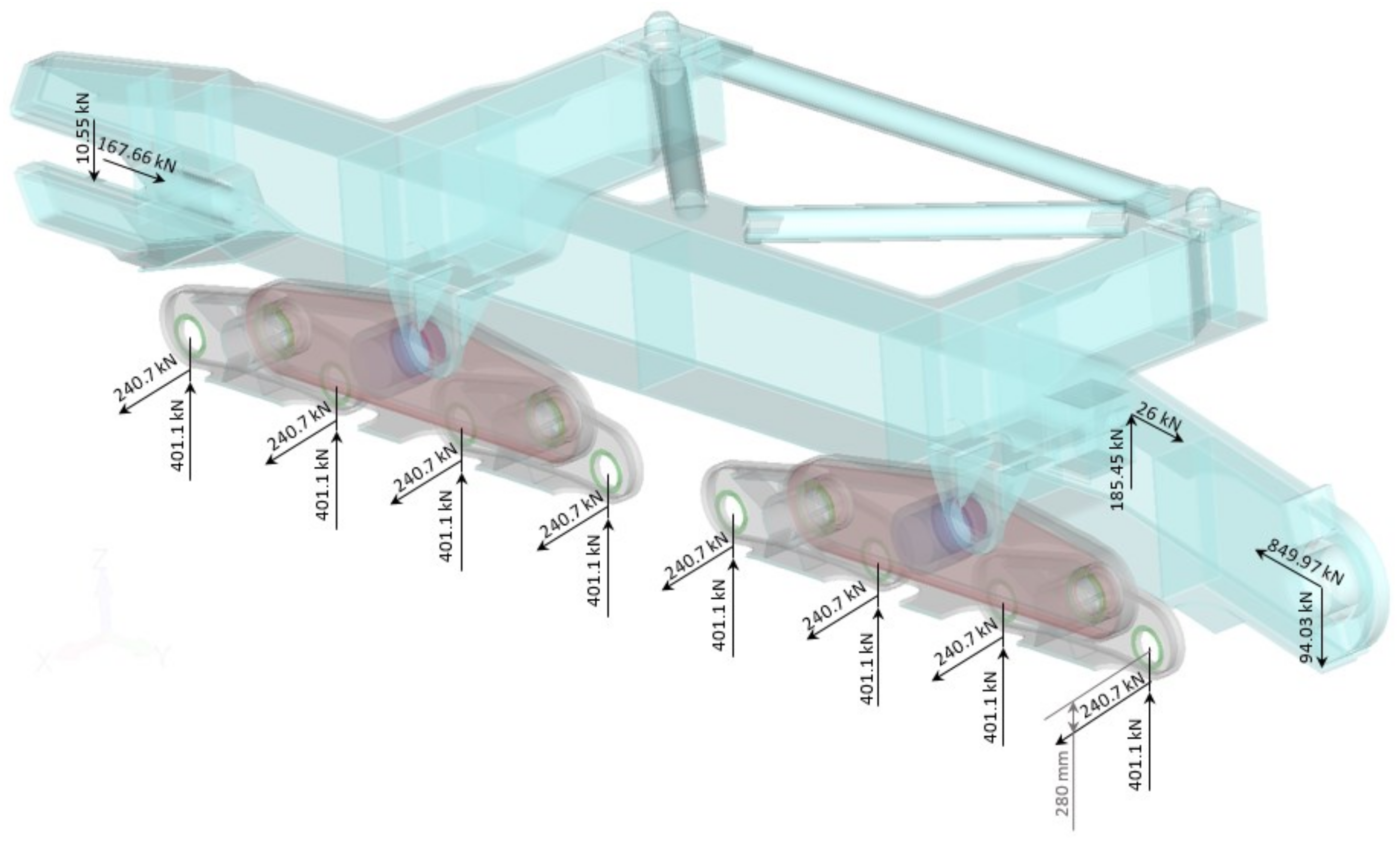
2.1. Mean Vertical Wheel Load

According to calculations [31,32], the vertical force per wheel is V T = 401.1   kN . The horizontal force, according to DIN22261-2 standard [30], is
H T = H T max = μ V T = 0.6 401.1 = 240.7   kN
where μ is coefficient of friction. The horizontal force acts on a point 280 mm distant from the wheel axis centre; see Figure 1.

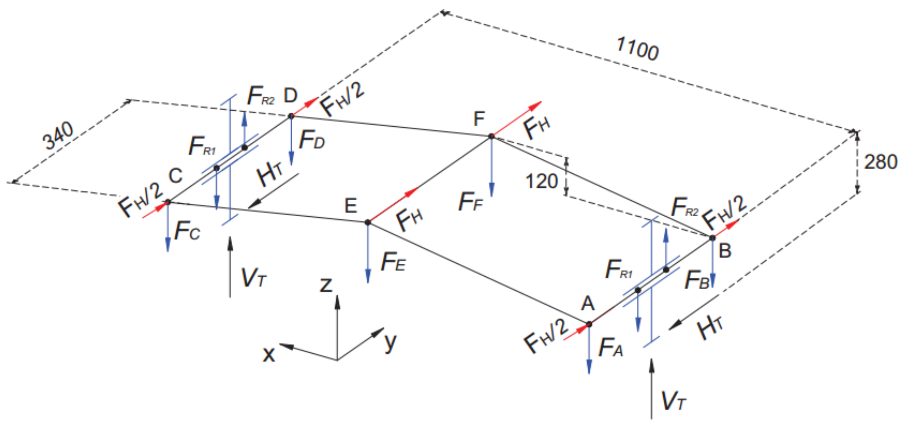
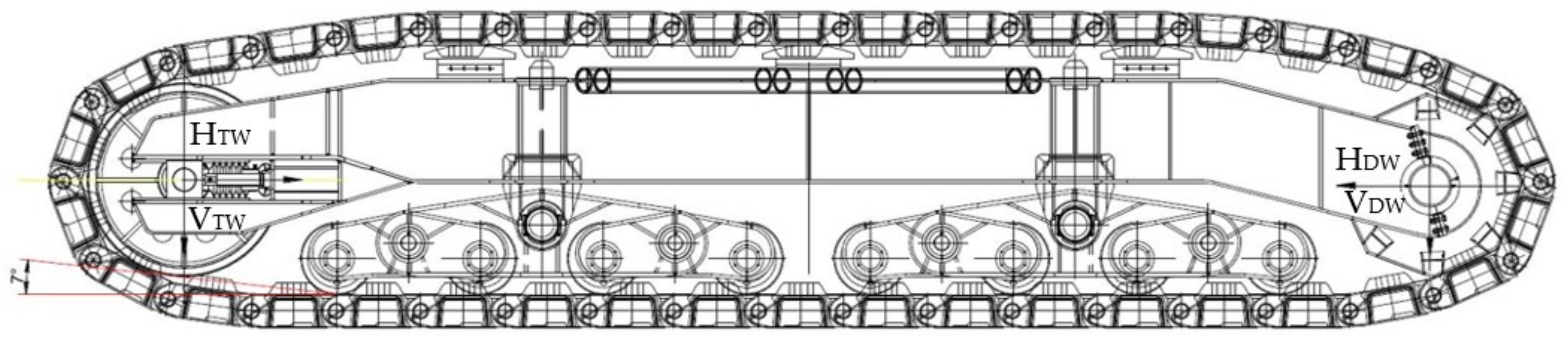
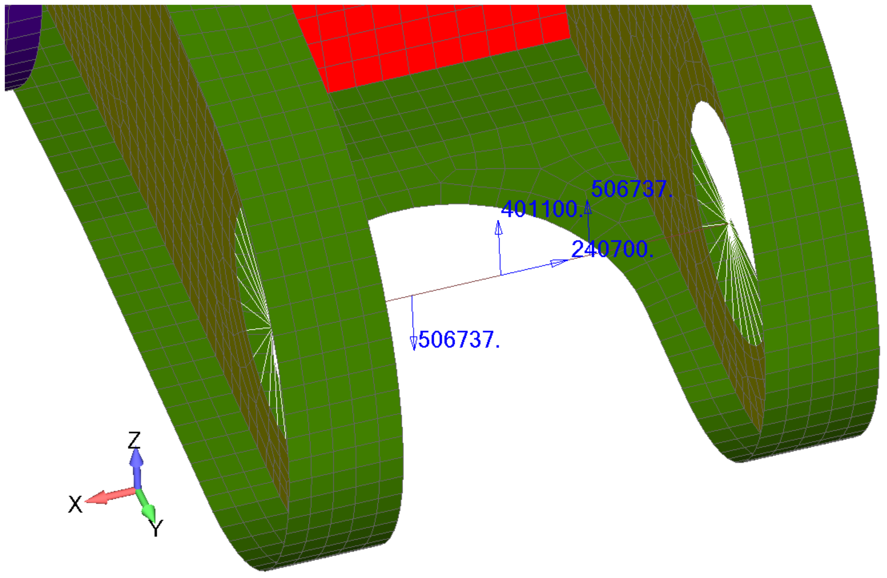
2.2. Loads on the Supporting Structure from the Tension of the Crawler’s Chain

Loads that these wheels apply to the supporting structure can be decomposed to the horizontal and vertical parts (Hdw, Vdw, Htw, Vtw); see Figure 2. The track chain is driven by a sprocket wheel, also known as a driving wheel (DW), while on the other side is an idler tension wheel (TW).
These load components are calculated using the following expressions [30,31]:
H D W = F P N + F m o t 1.6 cos 7 ° = 849.97   kN
V D W = F m o t 1.6 sin 7 ° = 94.03   kN
H T W = F P N ( 1 + cos 7 ° ) = 167.66   kN
V T W = F D W sin 7 ° = 10.55   kN
where F P N = 84.144   kN represents the preload force of chain links and F m o t 1.6 = 771.562   kN is the maximum driving force (when the motor is overload 60%, i.e., the maximum driving force of the motor is 160%) according to [30,31].
The positions of the motor and the reduction gearing regarding the support structure and the sprocket wheel are shown in Figure 3.
For motor torque M m o t = 437.6   Nm and transmission ratio i R = 864.639 , [31] momentum in the z direction is:
M Z = M m o t i R = 378366   Nm
therefore, the total force from the motor is:
F M O = M Z / 2.02 = 378366 / 2.02 = 187.31   kN
The vertical and the horizontal components [31] are calculated as:
V M O = F M O cos 8 ° = 185.45   kN
H M O = F M O sin 8 ° = 26   kN
Loads acting on the eight-wheel bogie are shown in Figure 4.

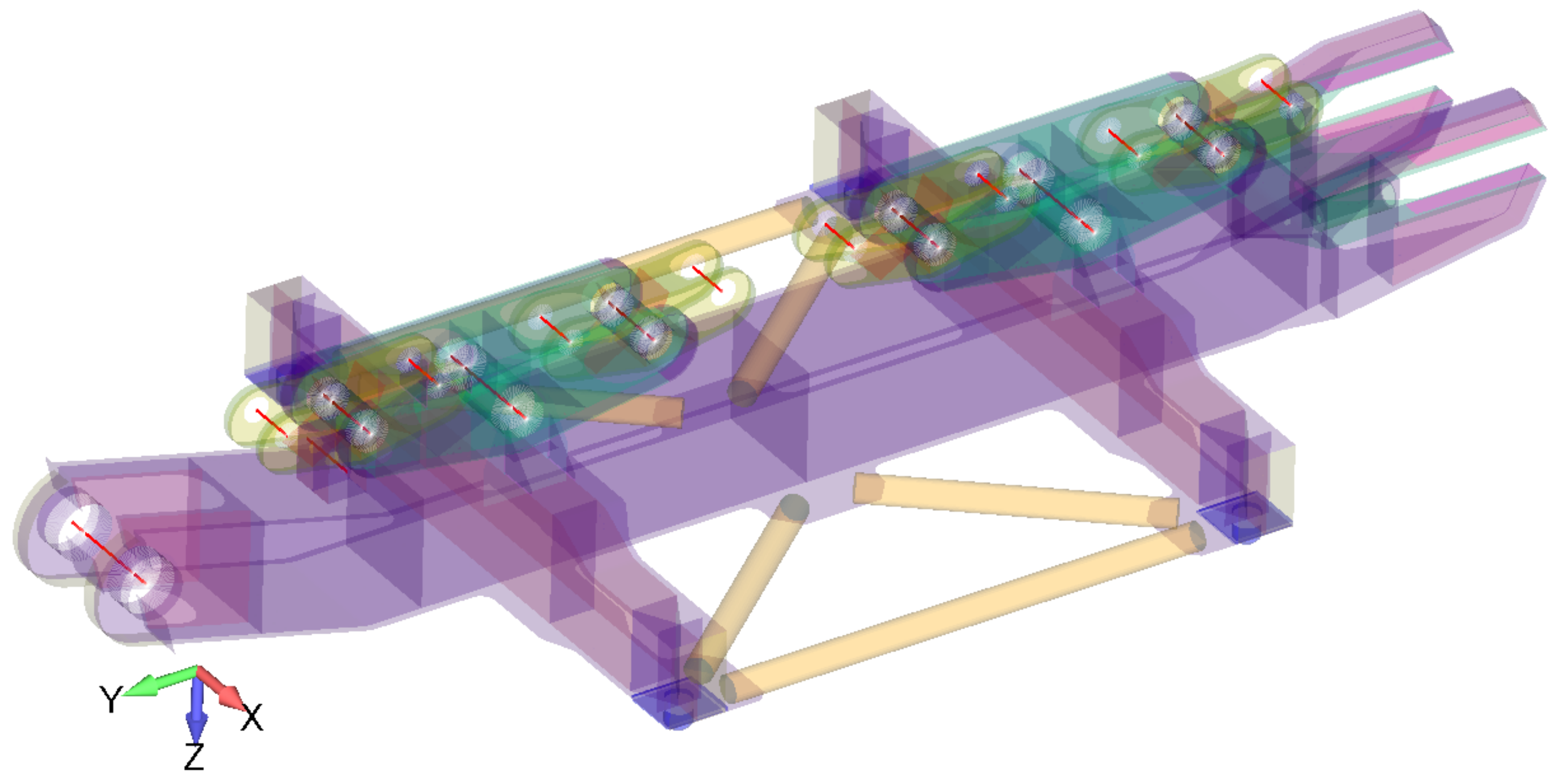
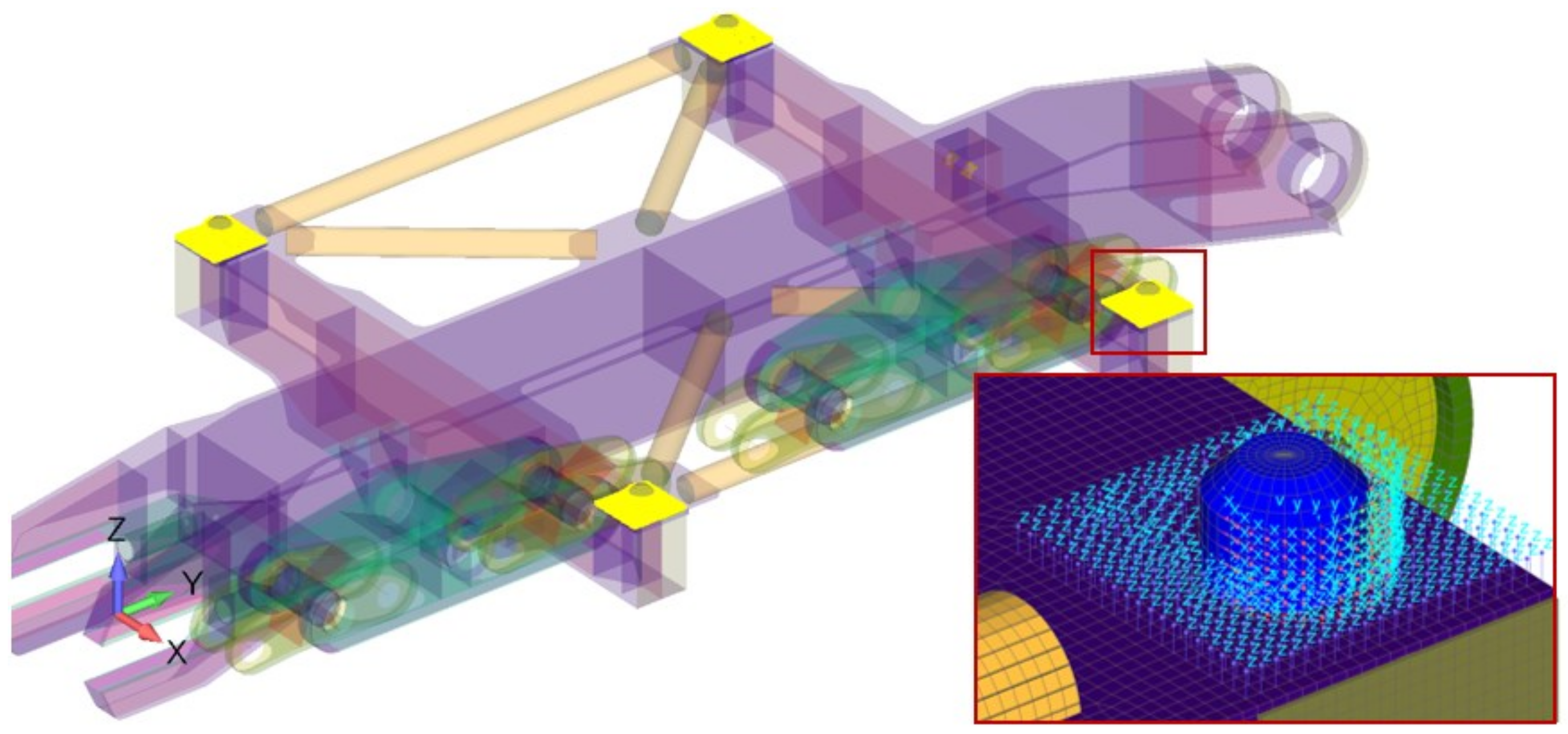
3. FEM Model of Eight-Wheel Bogie

Based on the CAD 3D model shown in Figure 5, a FEM model of the eight-wheel bogie is created in FEMAP [32] pre/post-processing software, as can be seen in Figure 6. A single eight-wheel bogie (EWB) is composed of two four-wheel bogies (FWB) and four two-wheel bogies (TWB); see Figure 5 and Figure 6.
The eight-wheel bogie is modelled with shell elements (element without mid nodes). The different colors in Figure 6 indicate the different thickness of the shell elements. The axes are modelled with beam elements; see Figure 7. In Figure 6, the shell and beam elements with the thickness/cross section option turned on is shown. The mandrels and support points of the drive station on the supporting bogie structure are modelled with 3D hex elements, which are the red-colored elements in Figure 8. The connections between the axles of the crawler wheels and the vertical plates of the two-wheel bogies are defined by rigid elements RB3; see Figure 7. The RBE3 rigid element is used to transmit loads, and rigid body motion (velocity) without adding rigidity to the model. The two-wheel bogie is supported by the four-wheel bogie. The connection between the TWB and FWB is realized by an axle modelled as a beam. The rigid RB3 elements are used to define the connection between the axle and the plate of the FWB. The same method was used for the connection between the FWB and EWB finite element models.
The surface on which the drive station rest is constrained in the vertical (z) direction, the outer surfaces of the mandrels are limited in the horizontal plane (x and y direction); see Figure 9.
The total number of elements in the whole model is 288,481, which includes all element types mentioned previously. The eight-wheel bogie is made from steel, with the material parameters given in Table 1.
In standard [30], the permissible stress approach is used in the designing process. For the analyzed load case HZG according to DIN 22261-2 standard [30], the safety coefficient is γ = 1.1 . Permissible stress is obtained from the yield stress according to the following equation:
σ a l l = R e , 0.2 γ
Yield stress and permissible stress are dependent on the thickness, as can be seen from Table 2.
In the finite element model (FEM), the track wheel axles of two-wheel bogies are loaded by the vertical force V T , by the horizontal force H T (Equation (1)), and by the bending moment gained by a reduction in the horizontal force. Vertical and horizontal wheel load is prescribed on the middle of the beam, which represents the wheel axis in the FEM model of the two-wheel bogie; see Figure 10. The bending moment is defined by two force, F R 1 and F R 2 ; see Figure 2 and Figure 10. The forces in the model are given in Newtons. Loads from the drive wheel to the supporting structure, Equations (2) and (3), are given on the middle of the drive wheel axle, Figure 11a. Figure 11b shows the load from the tension wheel; see Equations (4) and (5). Load V T W is given as pressure in the finite element model. Loads on the supporting structure from the motor are shown in Figure 12. These force components are prescribed as concentrated forces on the beam node; see Equations (8) and (9), and Figure 12.

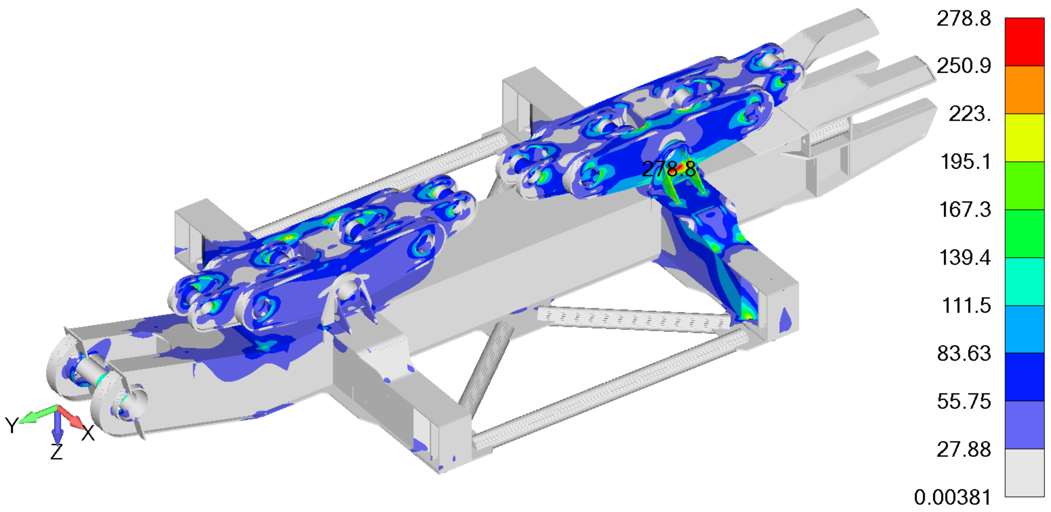
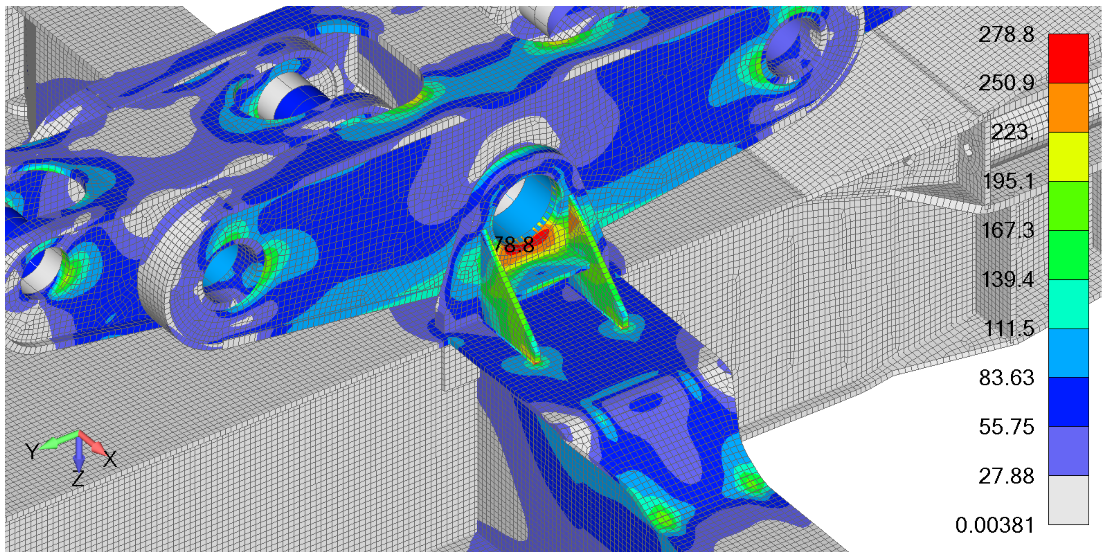
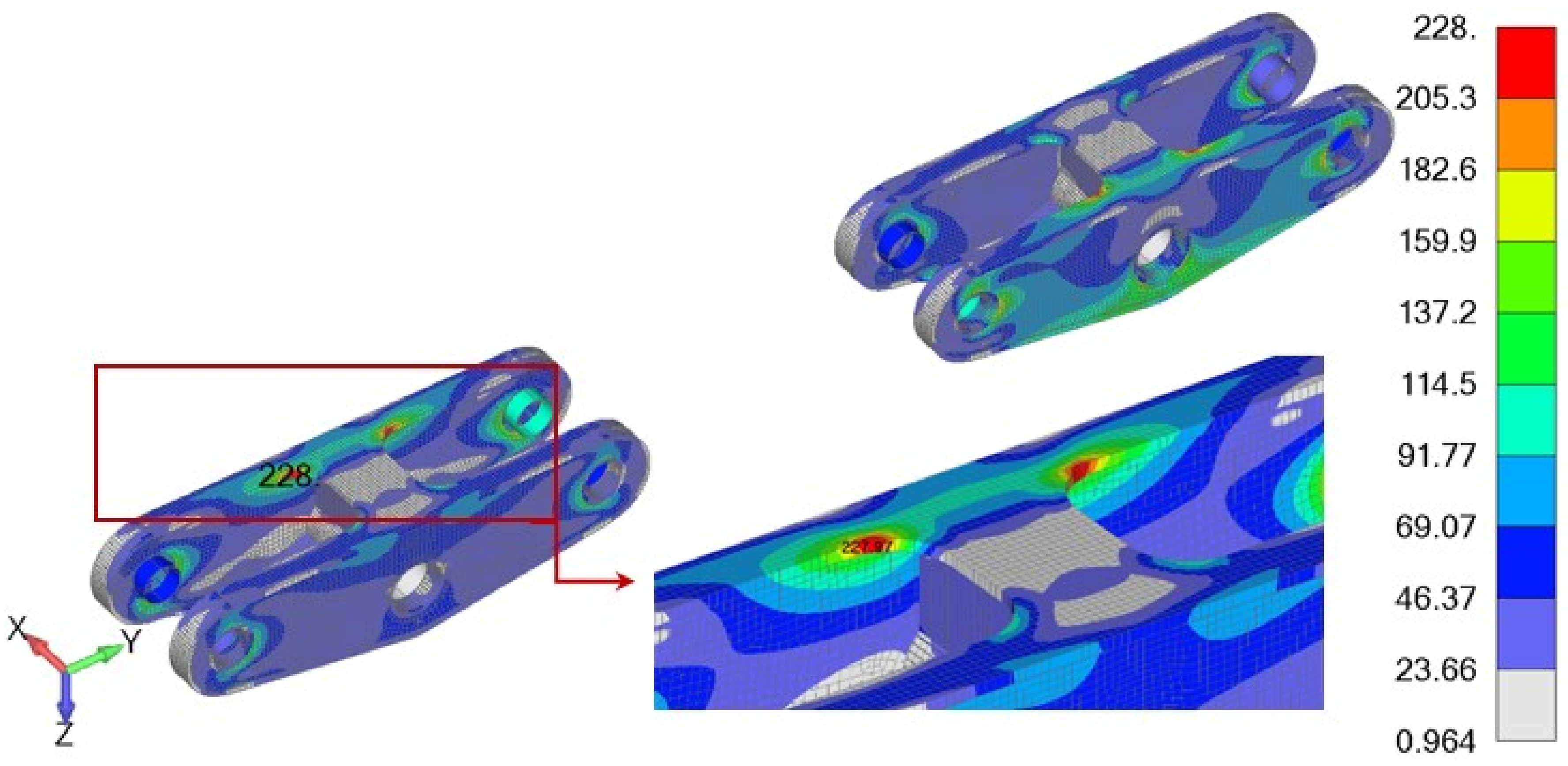
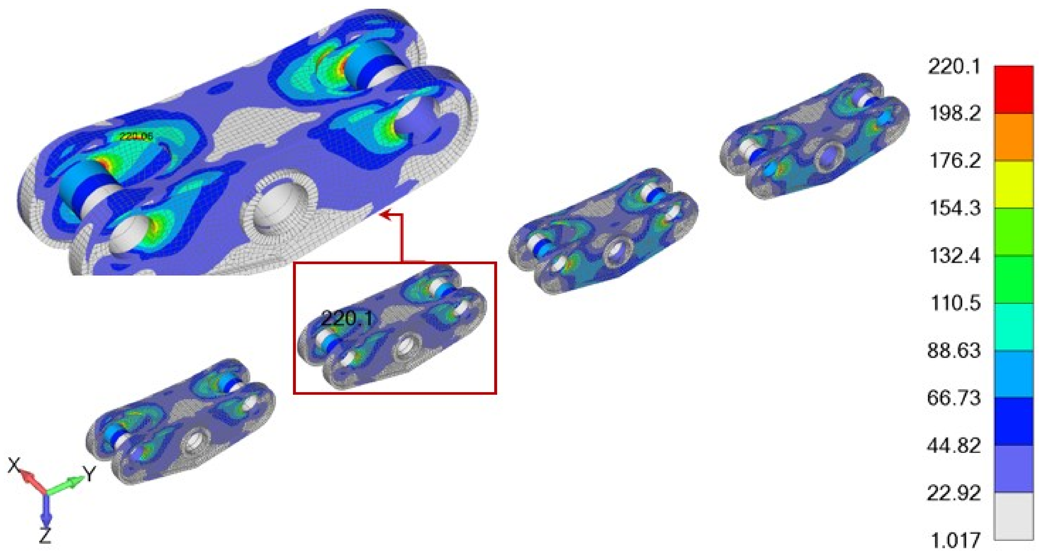
4. Results and Discussion

FEM analysis shows that in the assembly that consists of eight-wheel bogie, four-wheel bogie, and two-wheel bogie, the values of the von Mises stress in MPa are less than the permissible stress given in Table 2, as can be seen in Figure 13. The maximum value of the von Mises stress is in the fastening that holds the four-wheel bogie axis, which is given in detail in Figure 14.
The maximum calculated values of von Mises stress in the Mpa of the four-wheel bogie are shown in Figure 15. The maximum values of von Mises stress appear in the lower stiffening plates of the four-wheel bogie. The maximum values of von Mises stress in the two-wheel bogie are shown in Figure 16. The results presented in Figure 13 and Figure 14 show that, in most parts of the supporting structure, the values of von Mises stress are negligible, with zones of stress concentration located at the fastening and its near vicinity. Identification of the most critical areas of the supporting structure is important, because it shows maintenance crews where to look for potential problems such as fatigue cracks or corrosion. It can also be used for optimization during the design of new excavators, as some sections of the support structure can be made using thinner, lighter plates. On the other hand, four-wheel bogies and two-wheel bogies are very well-dimensioned (Figure 15 and Figure 16).
The analysis obtained the zones of maximum stress on TWB and FWB as being in the same positions as in papers [25,26,27]. Based on the above, it can be concluded that the presented method of modeling the connection between TWB and FWB, as well as FWB and EWB, can be used in the future.

5. Conclusions

In this paper, FEM analysis of key parts of the crawler travel gear is shown. The most important activity in the presented methodology is the calculation of loads based on the excavator dimensions/weight, and in accordance with DIN standard [30]. To ensure safe operation, the worst-case scenario must be considered. Based on the FEM results, Von Mises stress field is obtained for the whole assembly. Even in the areas of the highest stress concentration, permissible stress is never exceeded, hence, we can conclude that the analyzed assembly will not fail during the exploitation. The following degrees of safety were obtained: 1202 for eight-wheel bogie; 1513 for four-wheel bogie; 1567 for two-wheel bogie. This conclusion assumes that the analyzed parts are protected from corrosion, which can, if left untreated, reduce shell thickness in the critical areas and cause stress to exceed the permissible value. Another essential presumption is that the welded joints are good quality and that they contain no impurities that could be the source of fatigue cracks. Von Mises stress field obtained by FEM analysis can be used to spotlight high-risk areas, but also present opportunities for design optimization and weight reduction in less loaded areas.

Author Contributions

Conceptualization, S.V., M.Z. and R.V.; writing—original draft preparation, M.T. and S.V.; writing—review and editing, S.V. and A.P.; visualization, S.V. and A.P.; supervision, M.Z.; project administration, M.Z. All authors have read and agreed to the published version of the manuscript.

Funding

This research is supported by the Ministry of Education, Science and Technological Development, Republic of Serbia, grant TR32036 and 451-03-9/2021-14/200378, Nacionalni programi i projekti (mfkg.rs).

Data Availability Statement

Not applicable.

Conflicts of Interest

The authors declare no conflict of interest.

References

  1. Thermal Power Plants. Available online: https://www.eps.rs/eng/Poslovanje-EE/Pages/Termoelektrane.aspx (accessed on 10 November 2022).
  2. Bagger 293: Největší a Nejtěžší Vozidlo na Světě. Available online: https://www.stoplusjednicka.cz/bagger-293-nejvetsi-nejtezsi-vozidlo-na-svete (accessed on 27 January 2013).
  3. Savkovic, S.; Jovancic, P.; Djenadic, S.; Tanasijevic, M.; Miletic, F. Development of the hybrid MCDM model for evaluating and selecting bucket wheel excavators for the modernization process. Expert Syst. Appl. 2022, 201, 117199. [Google Scholar] [CrossRef]
  4. Moczko, P.; Pietrusiak, D.; Rusiński, E. Material handling and mining Equipment: International standards recommendations for design and testing. FME Trans. 2018, 46, 291–298. [Google Scholar] [CrossRef]
  5. Bošnjak, S.; Gnjatović, N. Bucket Wheel Excavators: Balancing and Dynamic Response of the Slewing Superstructure. In Proceedings of the 5th International Mechanical Engineering in XXI Century, Nis, Serbia, 9–10 December 2020. [Google Scholar]
  6. Bošnjak, S.; Pantelić, M.; Zrnić, N.; Gnjatović, N.; Đorđević, M. Failure analysis and reconstruction design of the slewing platform mantle of the bucket wheel excavator O&K SchRs 630. Eng. Fail. Anal. 2011, 18, 658–669. [Google Scholar] [CrossRef]
  7. Marinković, A.; Lazović, T.; Grbović, A.; Stanković, M.; Minewitsch, A. Contact stress study and FME analysis of large size thrust ball bearings. In Proceedings of the 5th International Conference on Power Transmissions BAPT2016, Ohrid, Republic of North Macedonia, 5–8 October 2016; pp. 7–14. [Google Scholar]
  8. Bošnjak, S.; Zrnić, N.; Simonović, A.; Momčilović, D. Failure analysis of the end eye connection of the bucket wheel excavator portal tie-rod support. Eng. Fail. Anal. 2009, 16, 740–750. [Google Scholar] [CrossRef]
  9. Bošnjak, S.M.; Arsić, M.A.; Zrnić, N.Đ.; Rakin, M.P.; Pantelić, M.P. Bucket wheel excavator: Integrity assessment of the bucket wheel boom tie-rod welded joint. Eng. Fail. Anal. 2011, 18, 212–222. [Google Scholar] [CrossRef]
  10. Danicic, D.; Sedmak, S.; Ignjatovic, D.; Mitrovic, S. Bucket Wheel Excavator Damage by Fatigue Fracture—Case Study. Procedia Mater. Sci. 2014, 3, 1723–1728. [Google Scholar] [CrossRef] [Green Version]
  11. Arsić, D.; Gnjatović, N.; Sedmak, S.; Arsić, A.; Uhričik, M. Integrity assessment and determination of residual fatigue life of vital parts of bucket-wheel excavator operating under dynamic loads. Eng. Fail. Anal. 2019, 105, 182–195. [Google Scholar] [CrossRef]
  12. Arsić, M.; Bošnjak, S.; Gnjatović, N.; Sedmak, S.; Arsić, D.; Savić, Z. Determination of Residual Fatigue Life of Welded Structures at Bucket-Wheel Excavators through the Use of Fracture Mechanics. Procedia Struct. Integr. 2018, 13, 79–84. [Google Scholar] [CrossRef]
  13. Savković, M.; Gašić, M.; Arsić, M.; Petrović, R. Analysis of the axle fracture of the bucket wheel excavator. Eng. Fail. Anal. 2011, 18, 433–441. [Google Scholar] [CrossRef]
  14. Bošnjak, S.M.; Savićević, S.D.; Gnjatović, N.B.; Milenović, I.L.; Pantelić, M.P. Disaster of the bucket wheel excavator caused by extreme environmental impact: Consequences, rescue and reconstruction. Eng. Fail. Anal. 2015, 56, 360–374. [Google Scholar] [CrossRef]
  15. Bošnjak, S.M.; Petković, Z.D.; Simonović, A.M.; Zrnić, N.; Gnjatović, N.B. ‘Designing-in’ failures and redesign of bucket wheel excavator undercarriage. Eng. Fail. Anal. 2013, 35, 95–103. [Google Scholar] [CrossRef]
  16. Fragassa, C.; Berardi, L.; Balsamini, G. Magnetorheological fluid devices: An advanced solution for an active control on the wood manufacturing process. FME Trans. 2016, 44, 333–339. [Google Scholar] [CrossRef] [Green Version]
  17. Beno, P.; Krilek, J.; Kovac, J.; Kozak, D.; Fragassa, C. The analysis of the new conception transportation cableway system based on the tractor equipment. FME Trans. 2018, 46, 17–22. [Google Scholar] [CrossRef] [Green Version]
  18. Martini, A.; Bellani, G.; Fragassa, C. Numerical Assessment of a New Hydro-Pneumatic Suspension System for Motorcycles. Int. J. Automot. Mech. Eng. 2018, 15, 5308–5325. [Google Scholar] [CrossRef]
  19. Pavlovic, A.; Fragassa, C.; Minak, G. Buckling analysis of telescopic boom: Theoretical and numerical verification of sliding pads. Teh. Vjesn. 2017, 24, 729–735. [Google Scholar] [CrossRef] [Green Version]
  20. Fragassa, C.; Minak, G.; Pavlovic, A. MEASURING DEFORMATIONS IN THE TELESCOPIC BOOM UNDER STATIC AND DYNAMIC LOAD CONDITIONS. Facta Univ. Ser. Mech. Eng. 2020, 18, 315–328. [Google Scholar] [CrossRef]
  21. Savković, M.; Gašić, M.; Petrović, D.; Zdravković, N.; Pljakić, R. Analysis of the drive shaft fracture of the bucket wheel excavator. Eng. Fail. Anal. 2012, 20, 105–117. [Google Scholar] [CrossRef]
  22. Rusiński, E.; Czmochowski, J.; Moczko, P. Half-shaft undercarriage systems—Designing and operating problems. J. Achiev. Mater. Manuf. Eng. 2009, 33, 62–69. [Google Scholar]
  23. Bošnjak, S.M.; Momčilović, D.B.; Petković, Z.D.; Pantelić, M.P.; Gnjatović, N.B. Failure investigation of the bucket wheel excavator crawler chain link. Eng. Fail. Anal. 2013, 35, 462–469. [Google Scholar] [CrossRef]
  24. Maślak, P.; Smolnicki, T.; Pietrusiak, D. Strain gauges measurements and fem analysis of elements of chassis of open cast mining machines. Tech. Gaz. 2013, 20, 655–658. [Google Scholar]
  25. Bošnjak, S.; Petković, Z.; Zrnic, N.; Pantelić, M.; Obradovic, A. Failure analysis and redesign of the bucket wheel excavator two-wheel bogie. Eng. Fail. Anal. 2010, 17, 473–485. [Google Scholar] [CrossRef]
  26. Bošnjak, S.; Petković, Z.; Gnjatović, N.; Milenović, I.; Jerman, B. Impact of the track wheel axles on the strength of the bucket wheel excavator two-wheel bogie. Teh. Vjesn. 2013, 20, 803–810. [Google Scholar]
  27. Bošnjak, S.; Petković, Z.; Gnjatović, N.; Milenović, I.; Milojević, G. Strength analysis of bucket wheel excavator’s eight-wheel equalizing system. In Proceedings of the 13th International Conference Research and Development in Mechanical Industry RaDMI 2013, Kopaonik, Serbia, 12–15 September 2013. [Google Scholar]
  28. Kojić, M.; Slavković, R.; Živković, M.; Grujović, N. Finite Element Method 1—Linear Analysis, 2nd ed.; University of Kragujevac, Mechanical Faculty: Kragujevac, Serbia, 2010. (In Serbian) [Google Scholar]
  29. Bathe, K. Finite Element Procedures; Prentice Hall: Hoboken, NJ, USA; Pearson Education, Inc.: New York, NY, USA, 2006. [Google Scholar]
  30. DIN 22261-2; Excavators, Spreaders and Auxiliary Equipment in Opencast Lignite Mines—Part 2: Calculation Principles. Deutsches Institut für Normung: Berlin, Germany, 2016.
  31. Durst, W.; Vogt, W. Bucket Wheel Excavator; Trans Tech Publications: Clausthal-Zellerfeld, Germany, 1989. [Google Scholar]
  32. FEMAP. User Guide Version 11.2; Siemens Product Lifecycle Management Software Inc.: Plano, TX, USA, 2016. [Google Scholar]
Figure 1. Loads acting on the two-wheel bogie.
Metals 13 00466 g001
Figure 2. Loads on the supporting structure from the tension of the crawler’s chain.
Metals 13 00466 g002
Figure 3. Motor and reduction gearing position.
Metals 13 00466 g003
Figure 4. Loads acting on the eight-wheel bogie.
Metals 13 00466 g004
Figure 5. CAD 3D model: (a) eight-wheel bogie; (b) four-wheel bogie; (c) two-wheel bogie.
Metals 13 00466 g005
Figure 6. FEM model: (a) eight-wheel bogie; (b) four-wheel bogie; (c) two-wheel bogie.
Metals 13 00466 g006
Figure 7. FEM model: the beam elements.
Metals 13 00466 g007
Figure 8. FEM model: 3D linear hex elements.
Metals 13 00466 g008
Figure 9. FEM model: boundary conditions.
Metals 13 00466 g009
Figure 10. FEM model: load of track wheel axles.
Metals 13 00466 g010
Figure 11. Loads on the supporting structure from the tension of the crawler’s chain: (a) H D W and V D W ; (b) H T W and V T W .
Metals 13 00466 g011
Figure 12. Loads on the supporting structure from the tension of the crawler’s chain: H M O and V M O .
Metals 13 00466 g012
Figure 13. Von Mises stress field.
Metals 13 00466 g013
Figure 14. Place of the maximum von Mises stress.
Metals 13 00466 g014
Figure 15. Von Mises stress field of the four-wheel bogie.
Metals 13 00466 g015
Figure 16. Von Mises stress field of the two-wheel bogie.
Metals 13 00466 g016
Table 1. Material (physical) parameters of the eight-wheel bogie.
MaterialModulus of Elasticity/MPaPoisson’s RatioDensity/kg·m−3
S355J2 + N2.1 × 1050.37850
Table 2. Material (mechanical) parameters of the eight-wheel bogie.
Thickness/mm Yield   Stress   R e , 0.2 / MPa Permissible   Stress   σ a l l / MPa
d ≤ 16355322.7
16 < d ≤ 40345313.6
40 < d ≤ 63335304.5
Disclaimer/Publisher’s Note: The statements, opinions and data contained in all publications are solely those of the individual author(s) and contributor(s) and not of MDPI and/or the editor(s). MDPI and/or the editor(s) disclaim responsibility for any injury to people or property resulting from any ideas, methods, instructions or products referred to in the content.

