Abstract
Thin-walled structures are widely used in anti-collision devices for various vehicles due to their light weight and high energy absorption. Offset collision is a common scene in various traffic accidents. Because the commonly used thin-walled structures do not consider this complex collision method, the energy absorption effect of the structure cannot meet the requirements. In this paper, a C-shaped frame structure composed of thin-walled steel tubes is proposed. The configuration of the structure is studied through theoretical analysis and numerical simulation, and it is found that the structure can absorb energy stably in the offset collision. The offset experiment and simulation were carried out, and the crashworthiness of the structure was investigated to verify the accuracy and feasibility of the numerical analysis method. A large-scale parameter simulation analysis was carried out, and the influence characteristics of the structure configuration, different materials and different sections were investigated. Based on the above test and numerical analysis results, an optimal design method for improving the crashworthiness of structures considering offset collisions is proposed. This paper can provide theoretical and technical support for the related research on the integrated anti-climbing energy-absorbing parts of rail trains under offset collision.
1. Introduction
Collision is a common mechanical phenomenon in the engineering field, such as car collision, train collision, ship–bridge collision, etc. The accidents have caused considerable property losses. According to statistics, traffic accidents caused millions of casualties every year [1]. Methods of reducing post-collision damage have become a very interesting research topic [2].
The quality of the response performance of the vehicle when it experiences a collision is characterized by crashworthiness, which often depends on the energy absorption capacity of the structure in the collision, but the load on the structure is usually unpredictable because of the contingency and suddenness of the collision. The deformation mode and energy absorption capacity vary greatly under different loading conditions, so it is necessary to develop structures that can stabilize energy absorption and obtain the energy absorption performance of such structures under different loading conditions. Only in this way can a more comprehensive evaluation of the crashworthiness of the structure be carried out. Offset collision is a very common scenario in all kinds of traffic accidents. The offset loading will make the structure unable to deform and absorb energy in the expected way. For example, the EU’s train crashworthiness standard EN15227 clearly requires that the performance of the vehicle must meet the requirements in the presence of a 40 mm height offset collision [3]. This paper is to study the response of the structure in the offset collision scenario, which has strong practical significance.
Thin-walled structures have the advantages of light weight and large energy absorption and are widely used in various projects and vehicles. The academic community has carried out considerable research on the crashworthiness of thin-walled structures [4,5,6,7,8]. Since a thin-walled tube can form a large number of plastic hinges to absorb the collision energy when it is loaded along the axial direction, extensive research has been carried out on the axial energy absorption of this type of structure. Alexander, Jones, Abramowicz, and Wierzbicki [9,10,11,12] put forward a formula for calculating the average force for the axial compression of circular and square tubes, respectively.
In order to further improve the energy absorption efficiency of thin-walled pipes [13,14], researchers have also tried different methods, such as changing the section of thin-walled pipes to increase the plastic deformation area or filling with lightweight, energy-absorbing materials. Zhang [15] and Kim [16] found that the multicellular structure can significantly improve the energy absorption of thin-walled tubes, and the SEA (specific energy absorption) value can even be increased by 100%; a number of different formulas for calculating the average force of multicellular thin-walled structures are proposed.
In terms of filling materials for thin-walled pipes, Reid uses PU foam [17,18], Hanssen uses foamed aluminum [19,20], and Santosa uses honeycomb material [21]; they found that although the filling materials are different, several different types of composite structures can increase the energy absorption efficiency or reduce the peak force, which can significantly improve the crashworthiness of the structure.
In the actual collision, the thin-walled structure will not just bear the pure axial impact, and the oblique load will cause overall instability and will not lead to progressive deformation during the impact, so the resistance of the thin-walled structure under oblique compression crash performance has attracted considerable attention. Reid and Nagel found that inclined tubes can absorb more energy than straight tubes when they are obliquely compressed, and their energy absorption decreases with an increase in the loading inclination angle. When the inclination angle exceeds a value, the structure changes from progressive deformation to overall instability and the energy absorption drops significantly [22,23]. Tran [24] changed the section of the square tube to multicell tube, predicted the average force based on the simplified super-folded element theory, validated it by simulation, and proposed a multiobjective optimization design method of SEA and PCF (initial peak stress) based on the oblique collision coefficient. Qi and Yang [25,26] established the SEA and PCF Kriging surrogate models of trapezoidal, multicellular hollow and foam-filled square tubes with different loading angles through parametric simulation methods, and applied the MOPSO strategy to optimize the design, the results showed that different loading angles had different values for the optimization parameters. In order to reflect the crashworthiness of thin-walled tubes under oblique loading, they also adopted the concept of composite crashworthiness criterion in the optimization objective and proposed this as one of the optimization objectives. Zhang [27] fabricated a conical gradient tube and found that this type of tube has greater advantages than a simple circular tube as an energy-absorbing element under oblique loading. When the loading angle was 15°, the energy absorption of the conical gradient tube increased by about 80%, indicating that the oblique bearing capacity of the structure can be greatly improved through structural changes and optimization. Kecman [28] found that rectangular tubes and square tubes can be divided into four stages when they are bent. The plastic hinge method can be used to analyze the bending failure modes of rectangular tubes and square tubes and deduce the relationship of bending moment and bending angle. They also verified the correctness of the formula through 56 static pressure tests, which are used as reference for the subsequent research on the bending of rectangular tubes. Poonaya [29] believed that the bending failure of thin-walled circular tubes can be divided into three stages: elastic section, plateau section, and failure section. Through theoretical derivation, the bending moment and angle formulas of different stages were obtained, which can better predict the bending moment of thin-walled circular tubes during the bending process. Bambach [30,31,32] conducted an in-depth analysis of the dynamic response of carbon steel, stainless steel pipes, and concrete-filled carbon steel under lateral impact and deduced the change of structural bearing capacity during the deformation process. They corrected the structural bearing capacity under different boundary conditions. It is found that material properties, fillers, and restraint forms have a great influence on the lateral bearing capacity of thin-walled square and round tubes. In order to improve the lateral impact crashworthiness of thin-walled tubes, Wang [33] added partition plates in different directions in the square tube to study the effect of different partition arrangements on the lateral bearing capacity. Tang [34] changed the section shape and comparing the changes in the crashworthiness of sections with different geometric shapes under lateral impact. Zhang [35] used a folded thin-walled structure to analyze the changes in its energy absorption capacity and crushing force under three-point bending. The results show that adding ribs along the loading direction can significantly improve the crashworthiness of the structure. Additionally, some researchers use a frame composed of thin-walled parts as the energy-absorbing structure of the vehicle. For example, Xu and Li [36,37] used thin-walled metal to construct an end structure for a rail vehicle that could absorb energy in stages. They studied energy absorption capacity in frontal collision and used the response surface method to establish a surrogate model between energy absorption, peak force, and various parameters, and then optimized the designed structure.
From the references, it is found that thin-walled parts are widely used in engineering as a lightweight and efficient energy-absorbing material. There are many studies on thin-walled parts and their combined structures, such as axial compression, oblique compression, and lateral compression of thin-walled structures. However, the research on offset loading of thin-walled tube structures is rare, and the energy absorption of offset collision is significantly lower than forward collision, which seriously affects the energy absorption performance of the structure [38,39,40,41]. The offset collision is similar to the oblique impact condition, so the goal of this paper is to propose a structure that can stably absorb energy in the offset collision and to study the change of its energy-absorbing performance during the collision. Additionally, we propose a crashworthiness optimization design method.
2. Material Preparation and Parameters Definition
2.1. Test Specimen
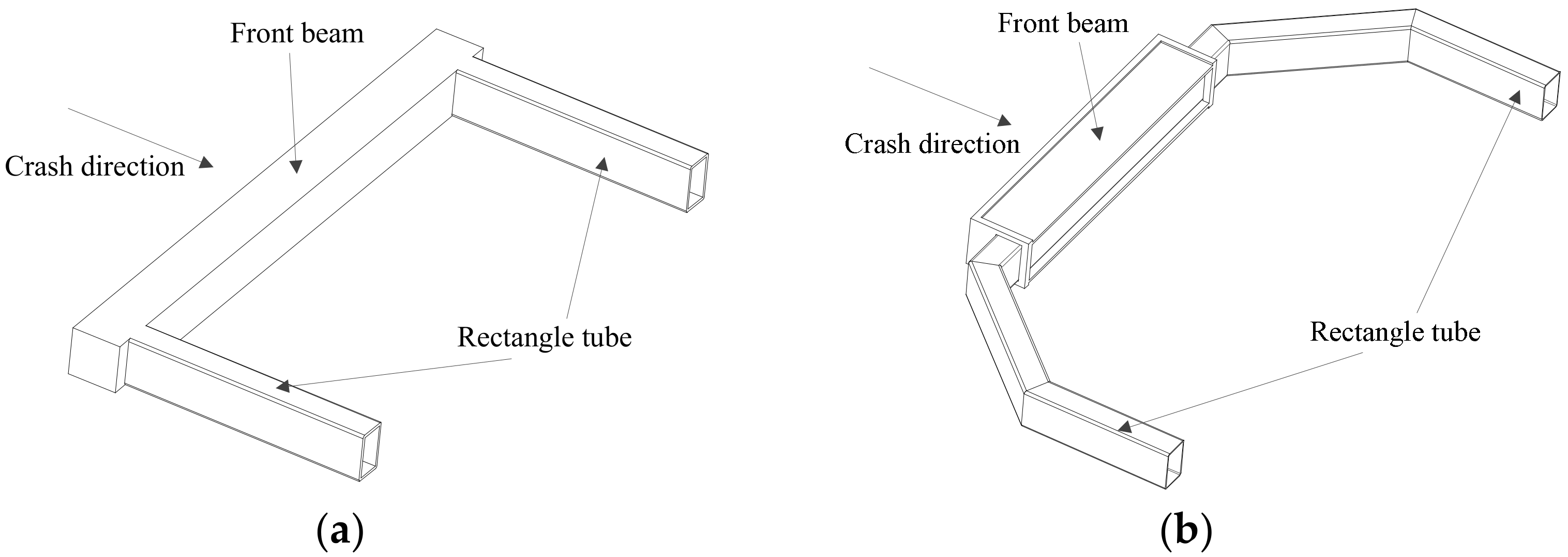
The front equipment of a common vehicle uses a C-frame energy-absorbing structure, as shown in Figure 1a. The front beam has a higher bearing capacity than the rectangular tubes on both sides. When a collision occurs, the front beam transmits the force to the rectangular tubes, and the rectangular tubes absorb energy. The newly designed structure in this paper is shown in Figure 1b. When the five-section tubular C-shaped frame collides, the front beam does not deform and the collision energy is absorbed by the bending deformation of the rectangular tubes on both sides.
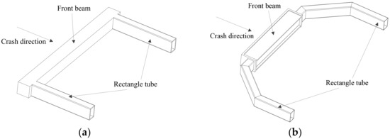
Figure 1.
Frame energy-absorbing structure. (a) Normal style, (b) five-section tubular C-shaped frame.
The longitudinal length and lateral width of the front-end chassis of the driver’s cab of the subway in China are about 1.3 m and 3 m, respectively. It is difficult and expensive to test with a true size. Some researches [24,25,35] found that if the theoretical or simulation results of the bearing capacity and energy absorption can be consistent with the test under a certain section size when the pipe members are subjected to lateral loads, the theoretical or simulation results are still credible when the size is enlarged by 3 times. Based on this study, the size of the test piece in this paper is about 1/3 of the actual vehicle. Two plates are welded to the root of the rectangular tube of the test piece. During the test, the test piece is installed on the fixture through the tooling plate with 8 screws, and a load is applied to the front beam. During the test, the load of the structure crushing process should be recorded automatically.
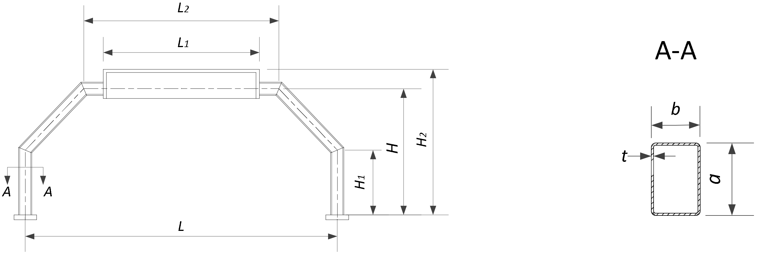
The parameters of the specimen are defined as shown in Figure 2, in which the parameters L, L1, L2, H, H1, and H2 determine the structural configuration, and the parameters a, b, and t characterize the cross-sectional shape of the structure. In this study, L, H, and H2 are fixed values, and L1, L2, H1, a, b, and t are variable.
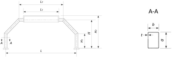
Figure 2.
Parameters of five-segment tubular C-shaped frame.
In this study, 301 L stainless steel, a material commonly used in rail vehicles, was selected to make specimens. The fixed parameters of the structure are: L = 960 mm, H = 390 mm, H2 = 450 mm; the rest of the parameters are variables.
2.2. Test Preparation
2.2.1. Drop Weight Test
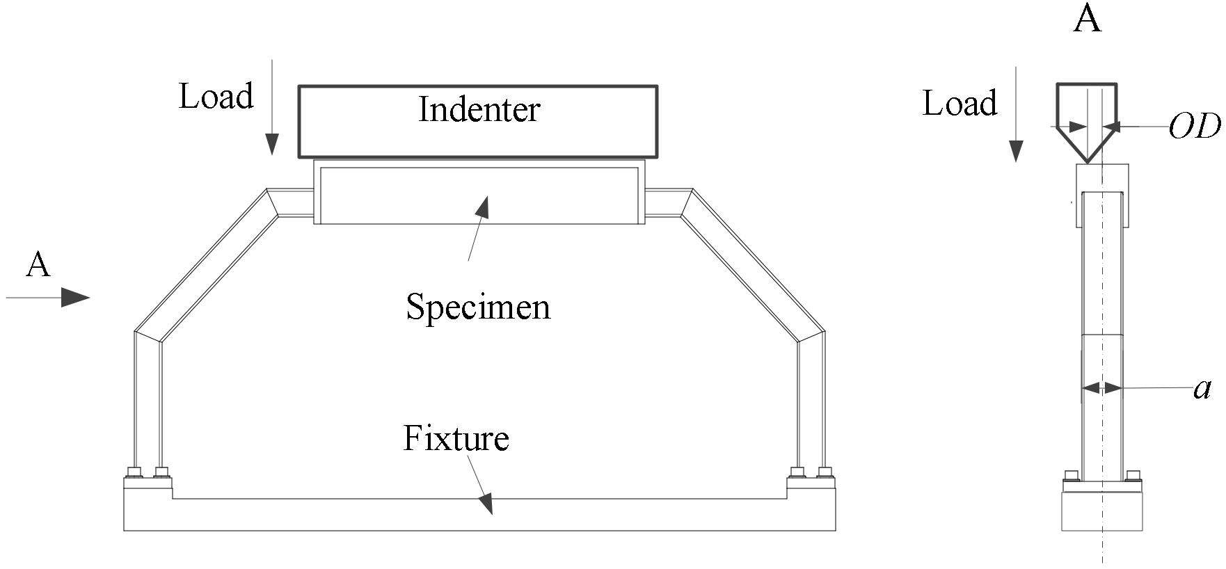
In order to demonstrate the load-bearing performance of the material under real working conditions, this test is carried out by means of drop weight loading. The installation and loading of the specimen are shown in Figure 3. When the center line of the indenter deviates from the center of the loading surface, an offset load can be applied to the frame structure, and the offset distance is represented by OD in this paper.
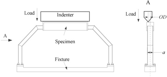
Figure 3.
Loading method.
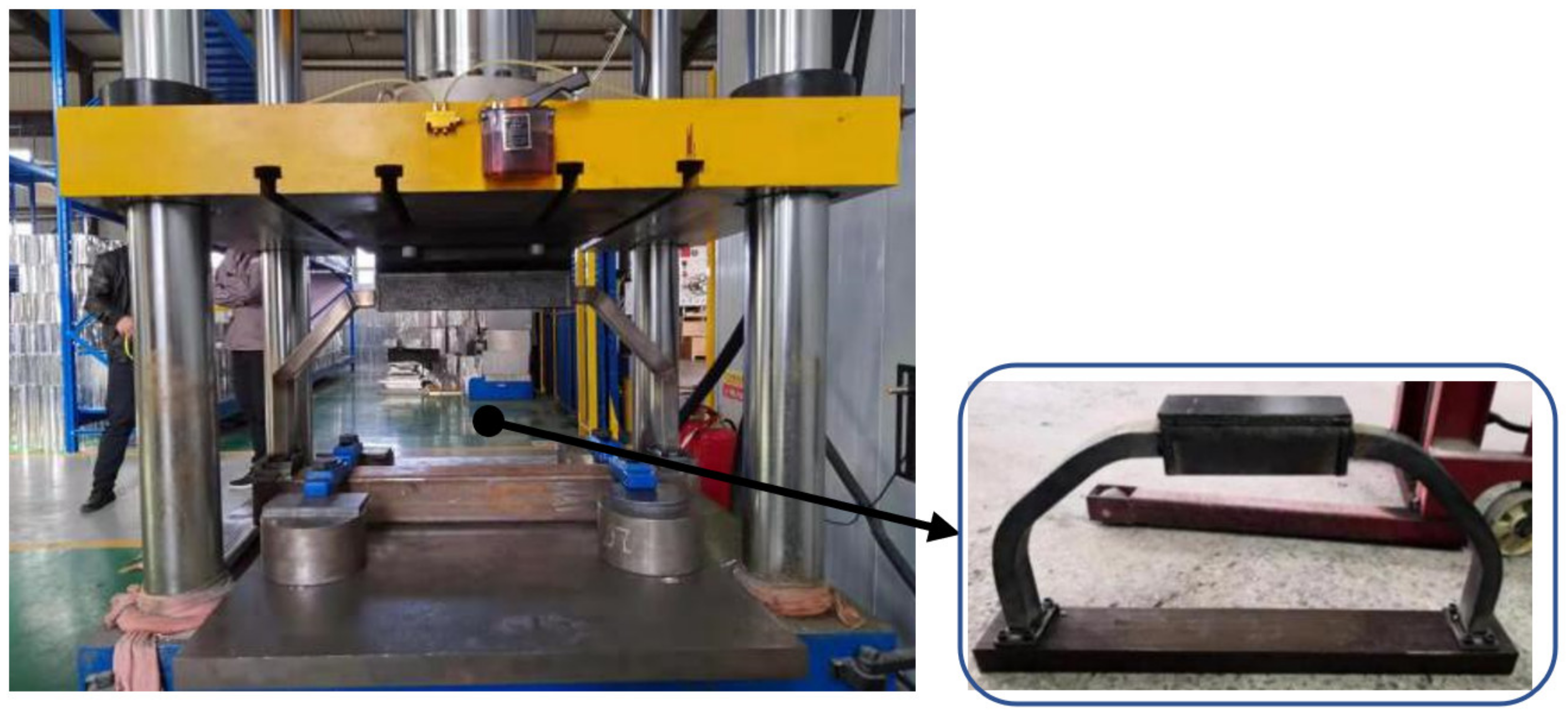
The dynamic test adopts the drop weight test equipment. The installation of the specimen is shown in Figure 4. The initial speed of the collision is controlled by the height of the drop weight, and the impact energy is adjusted to match the weight of the drop weight. In the test, the magnetic grid is used to measure the loading displacement and the dynamic force sensor FC-200t to measure the crushing force and use a high-speed camera to record the deformation process of the specimen.
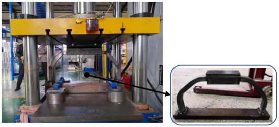
Figure 4.
Drop weight loading diagram.
The impact speed of all tests in this study before it hits the specimen is 25 km/h, the drop weight height is 2.5 m, and the drop weight is 425 kg, ensuring that the energy-absorbing stroke of the frame can reach more than 200 mm. The offset loading in this paper is realized by adjusting the relative position between the specimen and the hammer head. The offset distance OD in this paper is 10 mm.
2.2.2. Dynamic Simulation Settings
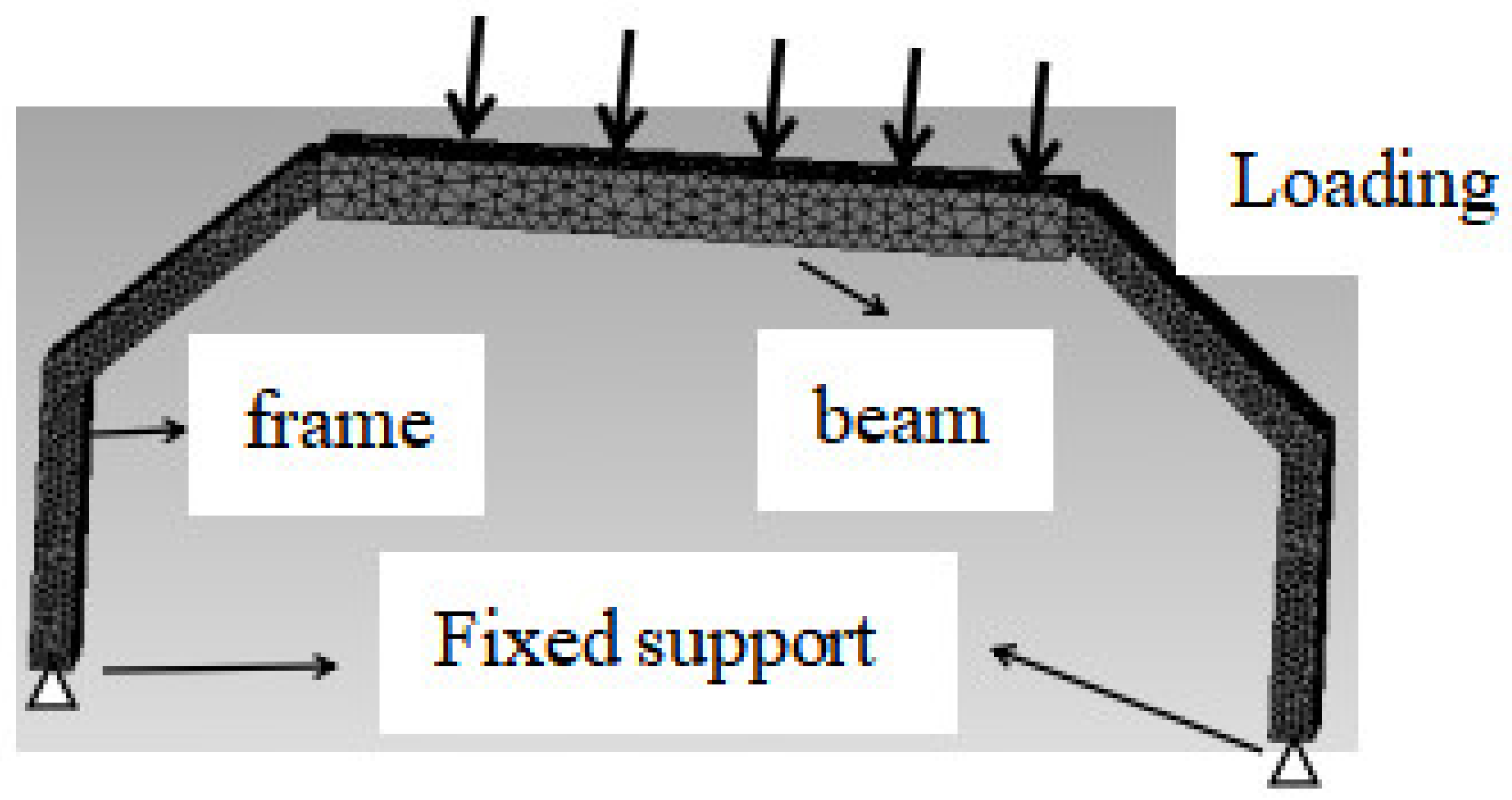
The establishment, calculation and post-processing of the finite element model of this structure are based on the ANSYS/LS-DYNA module. The steel plate and section steel in the structure use shell element SHELL163, and the thicker steel plates use solid element SOLID164. The mesh size of each component is divided according to the characteristics of the structural area, and the main mesh size is 5 mm; the material constitutive model adopts elastic plastic constitutive. The property of steel structure is density = 7930 kg/m3, elastic modulus = 194,000 MPa, Poisson’s ratio= 0.3, yield stress = 205 MPa, tangent modulus = 80 MPa. This model sets three types of contact methods: surface-to-surface, nodes-to-surface, and single-surface, of which single-surface uses automatic search for frictional contact, and the friction coefficient is 0.15. The loading speed of the dynamic simulation is 7 m/s under the drop weight condition. The upper end of the beam is loaded, the lower end is fixed, and the beam and the frame are bonded together (Figure 5). References [36,37] show that when the ratio of mesh size to element size is 0.125 (mesh size/element size = 0.125), the simulation results are in good agreement with the experimental results. In this paper, the setting of the mesh is based on this formula, and at the thinnest point of the tube, the mesh is not less than three layers.
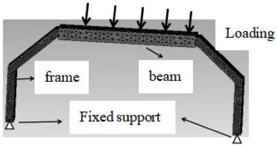
Figure 5.
Simulation settings.
2.3. Definition of Structural Crashworthiness
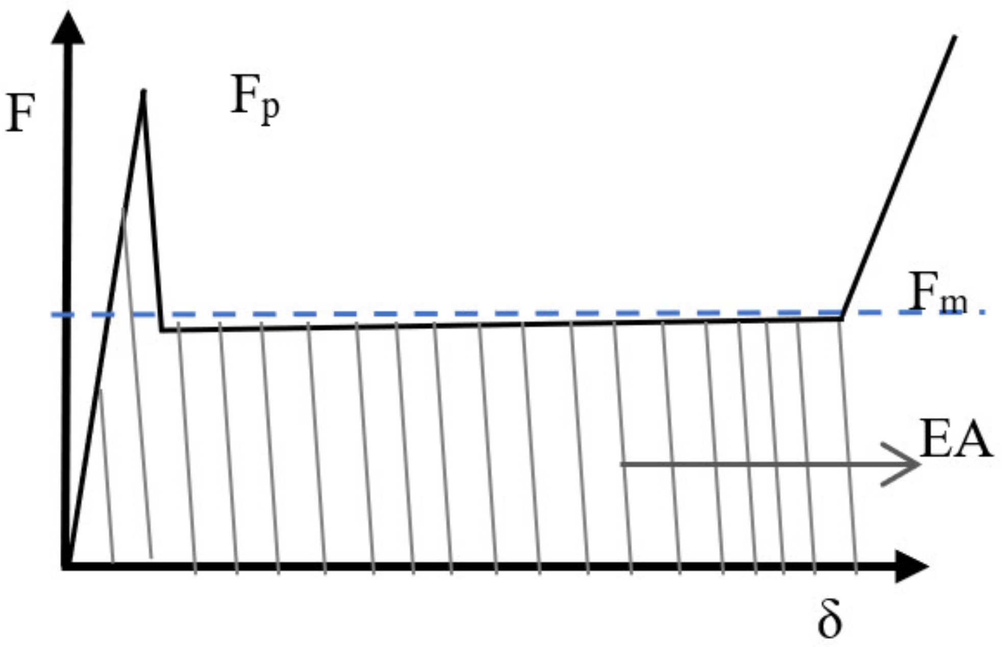
Common structural crashworthiness indicators include EA, SEA, Fm, Fp, CFE, etc. Figure 6 shows the stress-strain curve of the energy-absorbing element under ideal conditions, and their definitions are as follows. EA refers to the energy absorption of the structure during the collision process [42,43]: , where δ represents the total energy absorption stroke, F(x) represents the crushing force, and the shaded part in Figure 6 is the energy absorption.
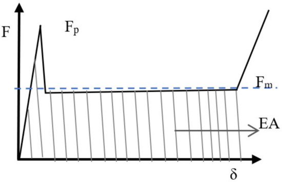
Figure 6.
Force–displacement curve of energy-absorbing element in ideal state.
SEA refers to the mass specific energy absorption of the structure: . where m represents the weight of the structure. Fm is the mean crushing force: . Fp is the crush peak force. CFE is crush force efficiency: .
3. Results and Discussion
3.1. Comparison of Simulation and Test Results
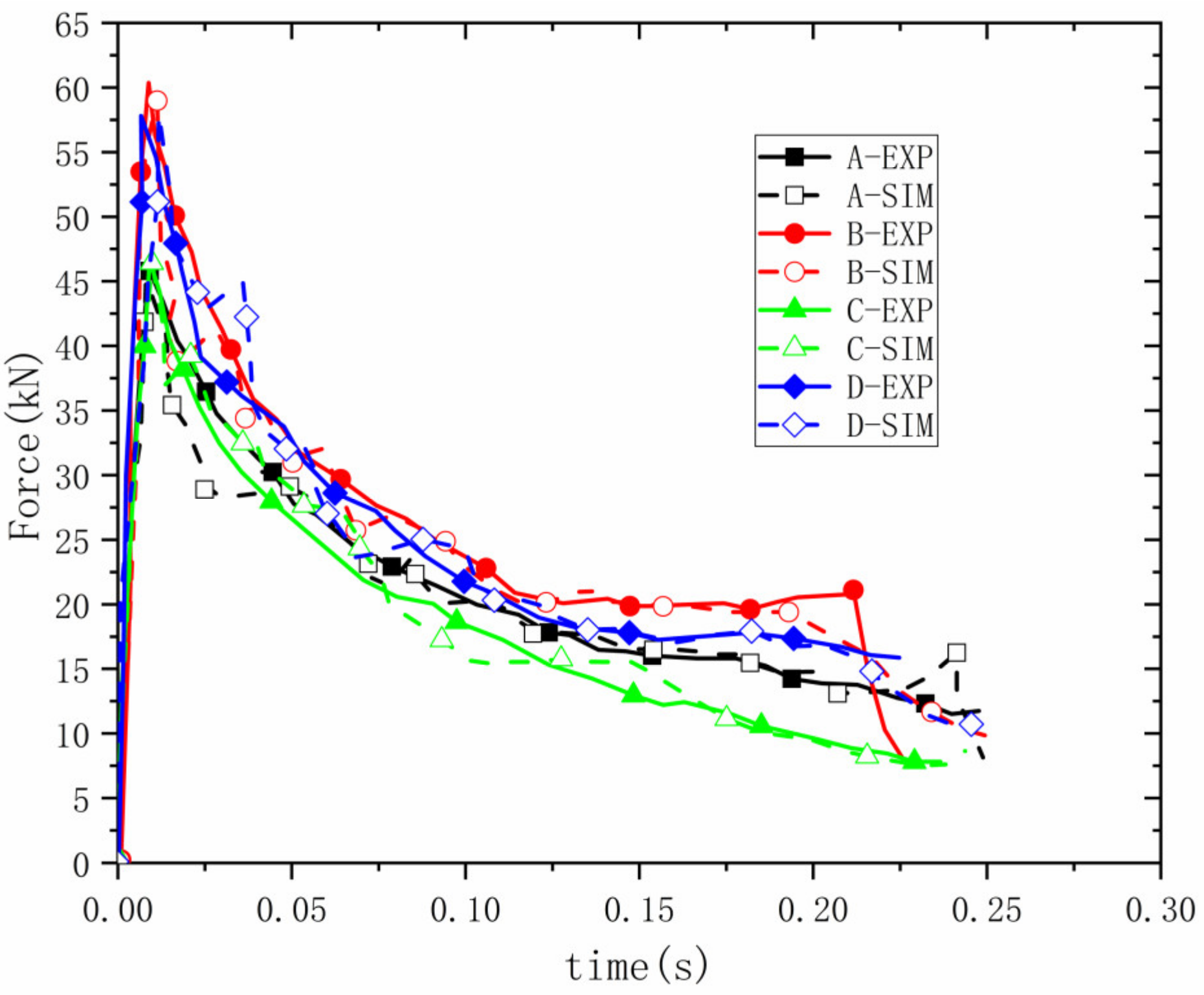
Firstly, several groups of five-section tubular C-shaped frames are simulated and compared with experiments. Taking four groups of samples 1A, 2B, 3C, and 4D as examples, the relevant parameters of the four groups of samples are shown in Table 1. The four groups of samples have the same cross-section. The overall height and width are different. The dynamic change process of the material is shown by means of simulation. First, through several sets of simulation data to compare the completed test data, it is found that the deformation process and stress curve of the material are relatively similar to the test. Therefore, the dynamic mechanical properties of the material are characterized by means of simulation. The forward collision test and simulation are compared, and the test and simulation results are shown in Figure 7. Through the comparison, it is found that the test and simulation results are relatively consistent. In order to reduce the number of tests, the method of simulation instead of test is adopted in the analysis.

Table 1.
Four groups of sample-related size parameters.
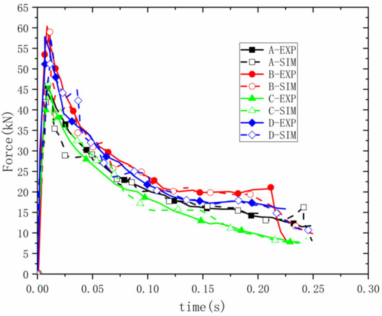
Figure 7.
Comparison between test and simulation of five-section tubular C-frame.
3.2. Parametric Simulation Results
3.2.1. Influence of Structural Parameter Changes on Crashworthiness
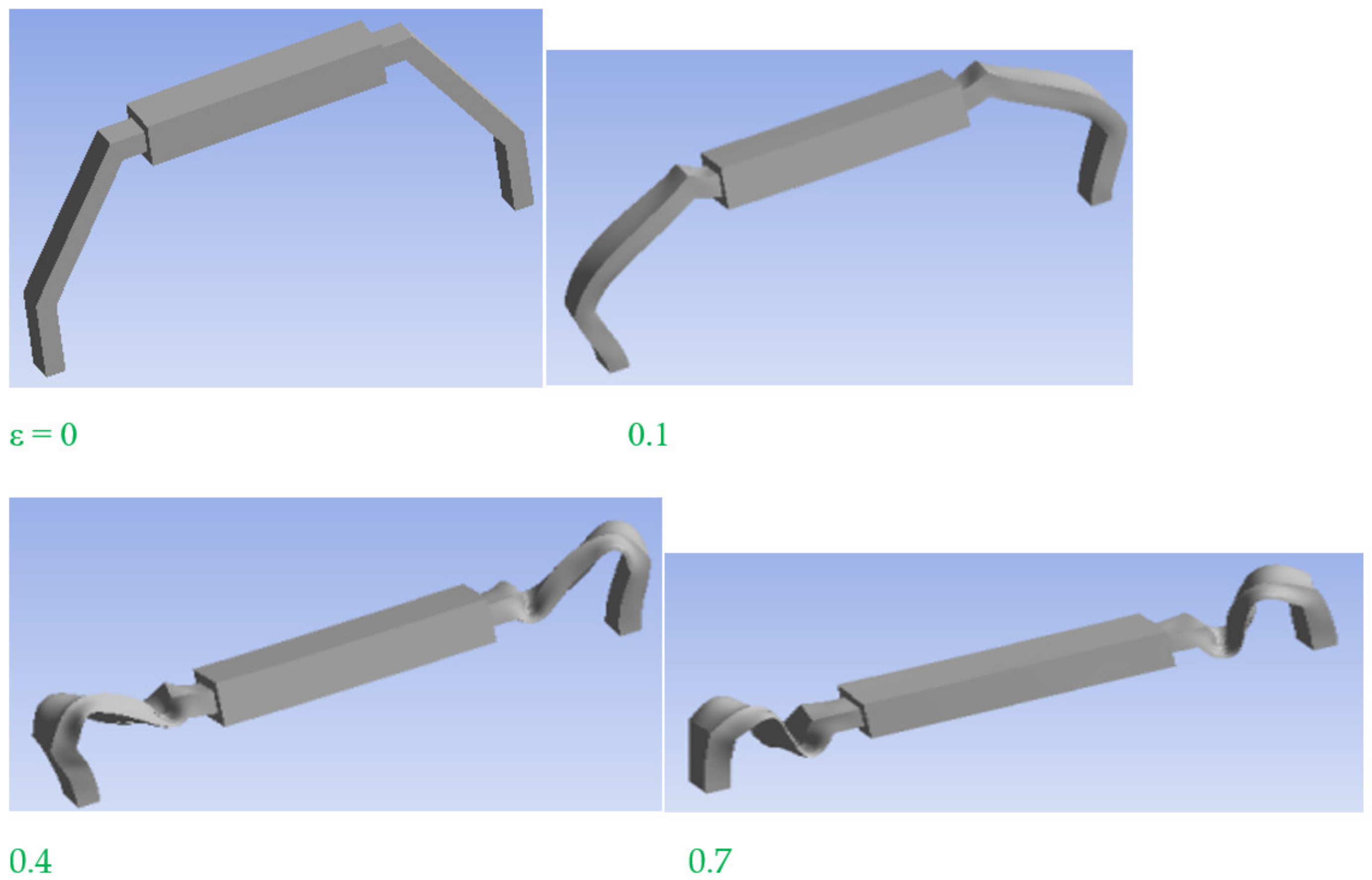
The center composite design model of design-expert is used to design the five parameters affecting the five-section tubular C-shaped frame. The structural parameter ranges are set as follows according to the actual conditions: L1 [280, 580] mm, H1 [140, 230] mm, a [50, 80] mm, b [25, 40] mm, t [2, 3.5] mm. The selected parametric simulation parameters are shown in Table 2. When studying different structural materials under impact load, it can be found through the above research that when the offset distance is greater, the stability performance is weaker. In order to demonstrate the performance of the five-section tubular C-shaped frame under extreme conditions, this part studies the mechanical properties of the load at 7 m/s when the offset distance is 10 mm. Figure 8 shows the simulation process of 1A.

Table 2.
Parametric structural design table.
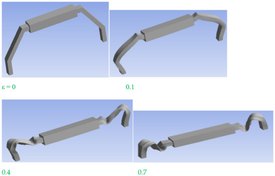
Figure 8.
Simulation deformation process.
In this study, two indicators EA and CFE were used to characterize the crashworthiness of the structure.
In order to optimize the energy absorption performance of the five-segment tubular C-shaped frame, the maximum energy absorption and the maximum CFE are taken as the optimization objectives, and the optimization problem is written in the following multiobjective optimization form:
Based on the fourth-order approximate EA and CFE empirical model, the expression can be written as follows:
EA = 1.45 + 0.0509 × A −1.28 × B − 0.079 × C + 0.104× D + 0.108 × E + 0.035 × AB − 0.027 × AC − 0.116 × AD − 0.047 × AE + 0.053 × BC + 0.0365 × BD − 0.036 × BE + 0.0499 × CD − 0.129 × CE + 0.0627 × DE − 0.189 × A^2 − 0.395 × B^2 − 0.00072 × C^2 − 0.128 × D^2 − 0.0958 × E^2 + 0.0979 × ABC − 0.0024 × ABD + 0.0385 × ABE + 0.159 × ACD − 0.111 × ACE − 0.114 × ADE + 0.0848 × BCD − 0.113 × BCE − 0.205 × BDE − 0.102 × CDE + 1.35 × A^2B + 0.115 × ABCD − 0.136 × ABCE − 0.0808 × ABDE + 0.0314 × ACDE + 0.101 × BCDE
R2 = 0.9854
CFE = 0.647 − 0.028 × A − 0.343852 × B − 0.0208 × C − 0.0027 × D − 0.002 × E + 0.0136 × AB + 0.0279 × AC − 0.02 × AD + 0.0014 × AE − 0.00158 × BC − 0.0154 × BD − 0.0351 × BE + 0.0288 × CD − 0.0305 × CE + 0.0234 × DE + 0.00353 × A^2 − 0.122 × B^2 − 0.00143 × C^2 − 0.0035 × D^2 + 0.00104 × E^2 + 0.0257 × ABC − 0.00808 × ABD + 0.0273 × ABE − 0.0026 × ACD − 0.00736 × ACE + 0.00198 × ADE − 0.0127 × BCD − 0.0142 × BCE − 0.0315 × BDE − 0.0285 × CDE + 0.32 × A^2B + 0.0205 × ABCD − 0.00665 × ABCE + 0.0062 × ABDE + 0.00475 × ACDE + 0.00994 × BCDE
R2 = 0.9433
R2 is introduced to evaluate the fitting error. The prediction accuracy of the model is very important to ensuring the optimization solution. Generally, a higher R2 indicates a higher model accuracy. When the model accuracy R2 > 0.9, it indicates that the prediction result is more accurate.
The optimal parameters are L1 = 423 mm, H1 = 140 mm, a = 50 mm, b = 40 mm, and t = 3.5 mm; the optimal energy absorption at this time is 2.98 MJ, and the CFE value is about 1. This shows that the smaller the length of the cross section, the larger the width, and the larger the thickness, the better the energy absorption performance of the material.
3.2.2. Influence of Configuration Parameters on Structural Crashworthiness
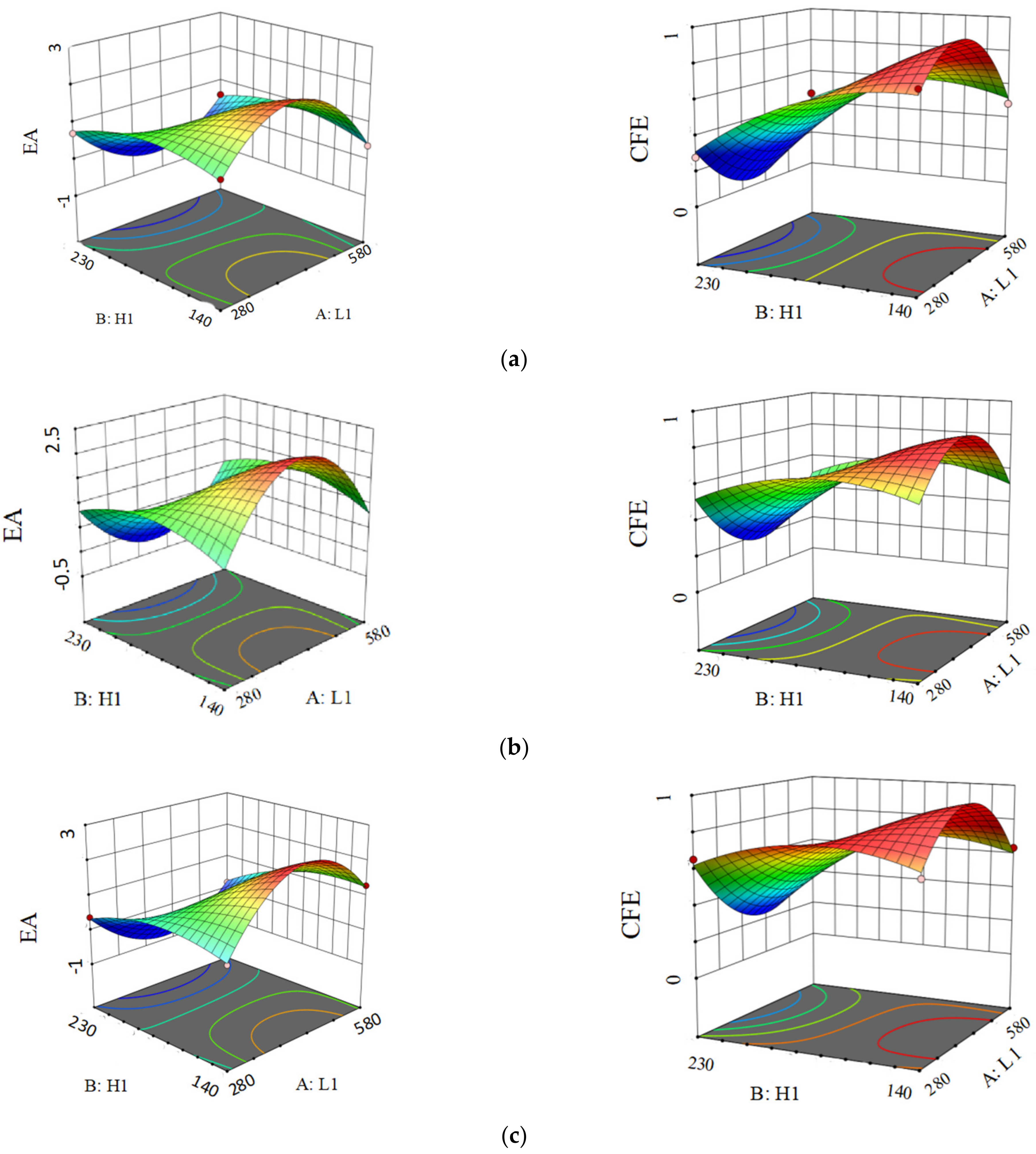
When the cross section parameters a, b, and t are fixed values, the changes of L1 and H1 will determine the frame type. Taking the data in Table 3 as an example, it can be concluded that when the cross-section is fixed, changing the height and width of the five-section pipe can be found; when the height increases, the energy absorption and CFE of the material decrease, which indicates that higher heights of the five-section tube are less conducive to the energy absorption of the material. This is because for offset loading, the higher the height of the five-section tube, the more easily it becomes unstable, which is not conducive to energy absorption.

Table 3.
Energy absorption and CFE under changing parameters L1 and H1.
Figure 9 shows the response surface graphs of energy absorption and CFE under different L1 and H1 under three sets of fixed a, b, and t parameters. It can be seen from the figure that both energy absorption and CFE will increase then decrease with the increase of L1 and H1.
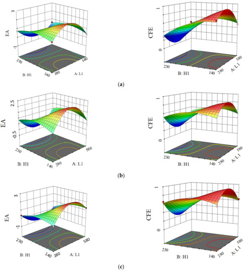
Figure 9.
Energy absorption and CFE response surfaces under different configuration parameters. (a) a = 80, b = 40, t = 3.5, (b) a = 62, b = 32.5, t = 2.75, (c) a = 50, b = 25, t = 2.
3.2.3. Influence of Different Materials on Structural Crashworthiness
The material and CFE performance analysis was carried out with two different materials (structural steel and aluminum 6061), and the data obtained are shown in Table 4 below.

Table 4.
Influence of different material properties on material crashworthiness.
Comparing the frames of three different structures, it can be found that the energy absorption of the two materials under the same structural size is not same. The energy absorption of the aluminum alloy material is smaller than that of the structural steel, which is related to the yield strength of the material. This shows that the choice of material is crucial to the crashworthiness of the structure.
3.2.4. Influence of Section Shape on Structural Crashworthiness
When L1 and H1 are fixed, changing a, b, or t can change the cross-sectional shape of the frame. Through a large number of calculations, it is concluded that when L1 and H1 are fixed, increasing the value of a will reduce the energy absorption of the material. Increasing the value of b and t increases the energy absorption of the material. The data obtained are shown in Table 5.

Table 5.
Influence of interface morphology on material crashworthiness.
4. Conclusions
In this paper, the traditional frame structure is improved and a five-section tubular C-shaped frame structure is prepared. First, the offset crashworthiness performance of several different structural parameters under dynamic loading is studied by means of experiment and simulation. Experiment is consistent with the simulation results.
Next, the influence of different structural parameters on the crashworthiness performance is discussed, mainly including the cross-sectional shape and the overall structural configuration. The deformation process of different types of materials is not same. The structural topography determines whether the deformation of the material is torsional buckling deformation or bending deformation, which is related to the overall structure. By means of simulation, the optimal structure size and optimal energy absorption value of the material are obtained through parametric design.
Furthermore, the effects of configuration, material properties, and cross-sectional shape on crashworthiness are discussed separately. The results showed that large size is not optimal and the value under a range will be better. The properties of different materials have different effects on performance. Under the same conditions, the performance of stainless steel is better than that of aluminum, which is related to the yield strength of the material. The crashworthiness of the material has the following relationship with the cross-sectional shape. When the length of the cross section is increased, the energy absorption of the material decreases; when the width of the cross section is increased, the energy absorption of the material increases; when the thickness of the cross section is increased, the energy absorption of the material increases. The above results provide some discussion for the stable energy absorption of the five-section frame under offset load.
Author Contributions
Conceptualization, W.W.; methodology, W.W.; software, R.L.; validation, W.W.; formal analysis, W.W.; investigation, Y.X.; resources, H.W.; data curation, F.Z.; writing—original draft preparation, W.W. and H.W.; writing—review and editing, H.W. and R.L.; visualization, Y.X.; supervision, W.W.; project administration, W.W.; funding acquisition, W.W. All authors have read and agreed to the published version of the manuscript.
Funding
This research received no external funding.
Institutional Review Board Statement
Not applicable.
Informed Consent Statement
Not applicable.
Data Availability Statement
Data available on request from the authors.
Conflicts of Interest
The authors declare no conflict of interest.
References
- Waters, H.; Hyder, A.; Phillips, T. Economic Evaluation of Interventions to Reduce Road Traffic injuries—A Review of the Literature with Applications to Low and Middie-income Countries. Asia Pac. J. Public Health 2004, 16, 23–31. [Google Scholar] [CrossRef] [PubMed]
- Li, R.; Cao, D.; Wu, H.; Wang, D. Collapse analysis and damage evaluation of typical simply supported double-pier RC bridge under truck collision. Structures 2021, 33, 3222–3238. [Google Scholar] [CrossRef]
- En15227-2008; Railway Applications—Crashworthiness Requirements for Railway Vehicle Bodies. British Standard: London, UK, 2008.
- Baroutaji, A.; Sajjia, M.; Olabi, A. On the crashworthiness performance of thin-walled energy absorbers: Recent advances and future developments. Thin-Walled Walled Struct. 2017, 118, 137–163. [Google Scholar] [CrossRef]
- Le, D.; Novak, N.; Arjunan, A.; Baroutaji, A.; Estrada, Q.; Tran, T.; Le, H. Crashworthiness of bio-inspired multi-stage nested multi-cell structures with foam core. Thin-Walled Struct. 2023, 182, 110245. [Google Scholar] [CrossRef]
- Lv, X.; Xiao, Z.; Fang, J.; Li, Q.; Lei, F.; Sun, G. On safety design of vehicle for protection of vulnerable road users: A review. Thin-Walled Struct. 2023, 182, 109990. [Google Scholar] [CrossRef]
- Estrada, Q.; Szwedowicz, D.; Rodriguez-Mendez, A.; Elías-Espinosa, M.; Silva-Aceves, J.; Bedolla-Hernández, J.; Gómez-Vargas, O.A. Identification of crashworthiness indicators of column energy absorbers with triggers in the form of cylindrical embossing on the lateral edges using artificial neural networks. Thin-Walled Struct. 2019, 140, 43–59. [Google Scholar] [CrossRef]
- Estrada, Q.; Szwedowicz, D.; Rodriguez-Mendez, A.; Elías-Espinosa, M.; Silva-Aceves, J.; Bedolla-Hernández, J.; Gómez-Vargas, O.A. Effect of radial clearance and holes as crush initiators on the crashworthiness performance of bi-tubular profiles. Thin-Walled Struct. 2019, 140, 43–59. [Google Scholar] [CrossRef]
- Alexander, J. An approximate analysis of the collapse of thin cylindrical shells under axial loading. Q. J. Mech. Appl. Math. 1960, 13, 10–15. [Google Scholar] [CrossRef]
- Abramowicz, W.; Jones, N. Dynamic progressive buckling of circular and square tubes. Int. J. Impact Eng. 1986, 4, 243–270. [Google Scholar] [CrossRef]
- Jones, N.; Abramowicz, W. Static and dynamic axial crushing of circular and square tubes. In Metal Forming & Impact Mechanics; Pergamon: Oxford, UK, 1985; pp. 225–247. [Google Scholar] [CrossRef]
- Wierzbicki, T.; Abramowicz, W. On the Crushing Mechanics of Thin-Walled Structures. J. Appl. Mech. 1983, 50, 727–734. [Google Scholar] [CrossRef]
- Lv, X.; Xiao, Z.; Fang, J.; Li, Q.; Lei, F.; Sun, G. Lightweight hybrid materials and structures for energy absorption: A state-of-the-art review and outlook. Thin-Walled Struct. 2023, 182, 109990. [Google Scholar] [CrossRef]
- Rogala, M.; Gajewski, J.; Gawdzińska, K. Crashworthiness analysis of thin-walled aluminum columns filled with aluminum–silicon carbide composite foam. Compos. Struct. 2022, 299, 116102. [Google Scholar] [CrossRef]
- Zhang, X.; Cheng, G.; Zhang, H. Theoretical prediction and numerical simulation of multi-cell square thin-walled structures. Thin-Walled Struct. 2006, 44, 1185–1191. [Google Scholar] [CrossRef]
- Kim, H.-S. New extruded multi-cell aluminum profile for maximum crash energy absorption and weight efficiency. Thin-Walled Struct. 2002, 40, 311–327. [Google Scholar] [CrossRef]
- Reid, S.; Reddy, T.; Gray, M. Static and dynamic axial crushing of foam-filled sheet metal tubes. Int. J. Mech. Sci. 1986, 28, 295–322. [Google Scholar] [CrossRef]
- Reid, S.; Reddy, T. Axial crushing of foam-filled tapered sheet metal tubes. Int. J. Mech. Sci. 1986, 28, 643–656. [Google Scholar] [CrossRef]
- Hanssen, A.; Langseth, M.; Hopperstad, O. Static and dynamic crushing of circular aluminium extrusions with aluminium foam filler. Int. J. Impact Eng. 2000, 24, 475–507. [Google Scholar] [CrossRef]
- Seitzberger, M.; Rammerstorfer, F.G.; Gradinger, R.; Degischer, H.P.; Blaimschein, M.; Walch, C. Experimental studies on the quasi-static axial crushing of steel columns filled with aluminium foam. Int. J. Solids Struct. 2000, 37, 4125–4147. [Google Scholar] [CrossRef]
- Santosa, S.; Wierzbicki, T. Crash behavior of box columns filled with aluminum honeycomb or foam. Comput. Struct. 1998, 68, 343–367. [Google Scholar] [CrossRef]
- Reid, S.; Reddy, T. Static and dynamic crushing of tapered sheet metal tubes of rectangular cross-section. Int. J. Mech. Sci. 1986, 28, 623–637. [Google Scholar] [CrossRef]
- Nagel, G.M.; Thambiratnam, D.P. Dynamic simulation and energy absorption of tapered thin-walled tubes under oblique impact loading. Int. J. Impact. Eng. 2006, 10, 1595–1620. [Google Scholar] [CrossRef]
- Tran, T.; Hou, S.; Han, X.; Nguyen, N.; Chau, M. Theoretical prediction and crashworthiness optimization of multi-cell square tubes under oblique impact loading. Int. J. Mech. Sci. 2014, 89, 177–193. [Google Scholar] [CrossRef]
- Qi, C.; Yang, S.; Dong, F. Crushing analysis and multiobjective crashworthiness optimization of tapered square tubes under oblique impact loading. Thin-Walled Struct. 2012, 59, 103–119. [Google Scholar] [CrossRef]
- Yang, S.; Qi, C. Multiobjective optimization for empty and foam-filled square columns under oblique impact loading. Int. J. Impact Eng. 2013, 54, 177–191. [Google Scholar] [CrossRef]
- Zhang, X.; Zhang, H. Relative merits of conical tubes with graded thickness subjected to oblique impact loads. Int. J. Mech. Sci. 2015, 98, 111–125. [Google Scholar] [CrossRef]
- Kecman, D. Bending collapse of rectangular and square section tubes. Int. J. Mech. Sci. 1983, 25, 623–636. [Google Scholar] [CrossRef]
- Poonaya, S.; Teeboonma, U.; Thinvongpituk, C. Plastic collapse analysis of thin-walled circular tubes subjected to bending. Thin-Walled Struct. 2009, 47, 637–645. [Google Scholar] [CrossRef]
- Bambach, M.; Jama, H.; Zhao, X.; Grzebieta, R. Hollow and concrete filled steel hollow sections under transverse impact loads. Eng. Struct. 2008, 30, 2859–2870. [Google Scholar] [CrossRef]
- Bambach, M. Design of hollow and concrete filled steel and stainless steel tubular columns for transverse impact loads. Thin-Walled Struct. 2011, 49, 1251–1260. [Google Scholar] [CrossRef]
- Yousuf, M.; Uy, B.; Tao, Z.; Remennikov, A.; Liew, J.R. Transverse impact resistance of hollow and concrete filled stainless steel columns. J. Constr. Steel Res. 2013, 82, 177–189. [Google Scholar] [CrossRef]
- Wang, Z.; Li, Z.; Zhang, X. Bending resistance of thin-walled multi-cell square tubes. Thin-Walled Struct. 2016, 107, 287–299. [Google Scholar] [CrossRef]
- Tang, T.; Zhang, W.; Yin, H.; Wang, H. Crushing analysis of thin-walled beams with various section geometries under lateral impact. Thin-Walled Struct. 2016, 102, 43–57. [Google Scholar] [CrossRef]
- Zhang, X.; Zhang, H.; Ren, W. Bending collapse of folded tubes. Int. J. Mech. Sci. 2016, 117, 67–78. [Google Scholar] [CrossRef]
- Xu, P.; Yang, C.; Peng, Y.; Yao, S.; Zhang, D.; Li, B. Crash performance and multi-objective optimization of a gradual energy-absorbing structure for subway vehicles. Int. J. Mech. Sci. 2016, 107, 1–12. [Google Scholar] [CrossRef]
- Li, J.; Gao, G.; Dong, H. Crushing analysis and multi-objective optimization of a railway vehicle driver’s cab. Thin-Walled Struct. 2016, 107, 554–563. [Google Scholar] [CrossRef]
- Yao, S.; Xiao, X.; Xu, P.; Qu, Q. Study on Impact Performance of Energy Absorbing Structures under Horizontal Offset Loading. In Proceedings of the International Conference on Applied Mechanics and Mechanical Automation, Phuket, Thailand, 6–7 August 2017; pp. 34–38. [Google Scholar] [CrossRef]
- Rui, D. Research on Development of an Energy Absorption and Anti-climbing Device for Metro Trains. Roll. Stock. 2014, 52, 25–28. [Google Scholar]
- Ismail, M.; Ismail, A. Eccentric crushing behavior of high strength steel tubes. Int. J. Mech. Mechatron. Eng. 2015, 15, 100–104. [Google Scholar]
- Jones, N.; Birch, S.E.; Birch, R.S.; Zhu, L.; Brown, M. An experimental study on the lateral impact of fully clamped mild steel pipes. Proc. Inst. Mech. Eng. Part E J. Process Mech. Eng. 1992, 206, 111–127. [Google Scholar] [CrossRef]
- Wu, X.; Yu, H.; Guo, L.; Zhang, L.; Sun, X.; Chai, Z. Experimental and numerical investigation of static and fatigue behaviors of composites honeycomb sandwich structure. Compos. Struct. 2019, 213, 165–172. [Google Scholar] [CrossRef]
- Xing, Y.; Yang, S.; Lu, S.; An, Y.; Zhao, E.; Zhai, J. Energy absorption and optimization of Bi-directional corrugated honeycomb aluminum. Compos. Part B Eng. 2021, 219, 108914. [Google Scholar] [CrossRef]
Disclaimer/Publisher’s Note: The statements, opinions and data contained in all publications are solely those of the individual author(s) and contributor(s) and not of MDPI and/or the editor(s). MDPI and/or the editor(s) disclaim responsibility for any injury to people or property resulting from any ideas, methods, instructions or products referred to in the content. |
© 2023 by the authors. Licensee MDPI, Basel, Switzerland. This article is an open access article distributed under the terms and conditions of the Creative Commons Attribution (CC BY) license (https://creativecommons.org/licenses/by/4.0/).

