
Compelling Evidence for the Role of Retained Austenite in the Formation of Low Cycle Fatigue Extrusions in a 9Ni Steel

 and
and 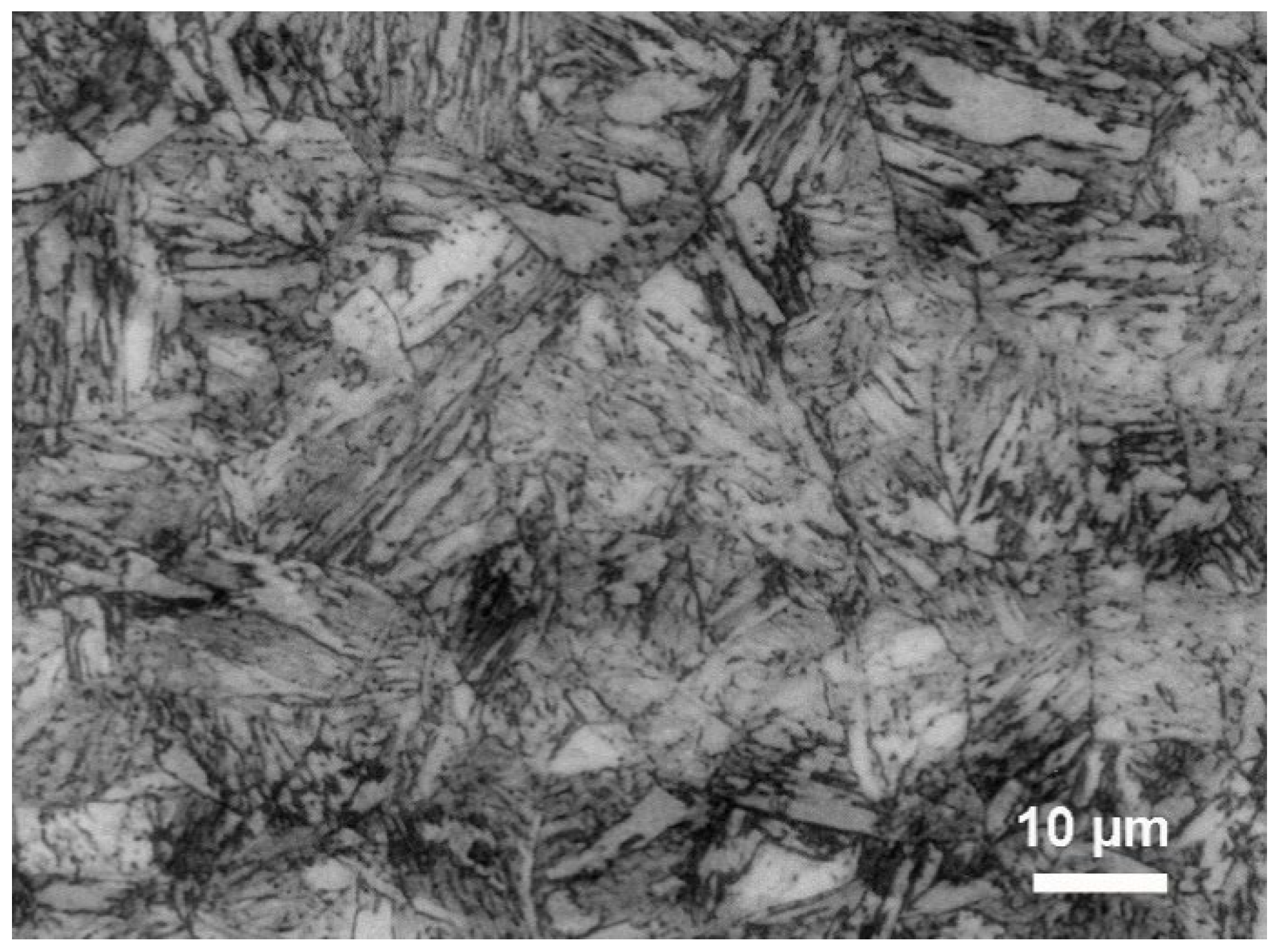
Abstract
1. Introduction
2. Material and Methods
2.1. Material and Conventional Techniques for Microstructure Identification
2.2. Fatigue Testing
3. Results and Discussion
3.1. Preliminary Results
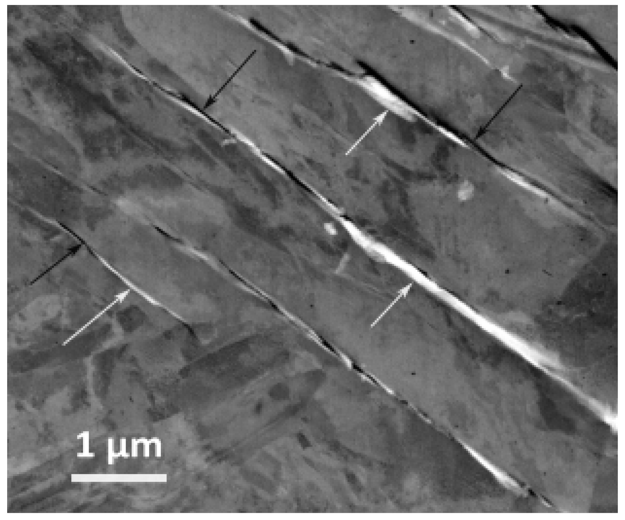
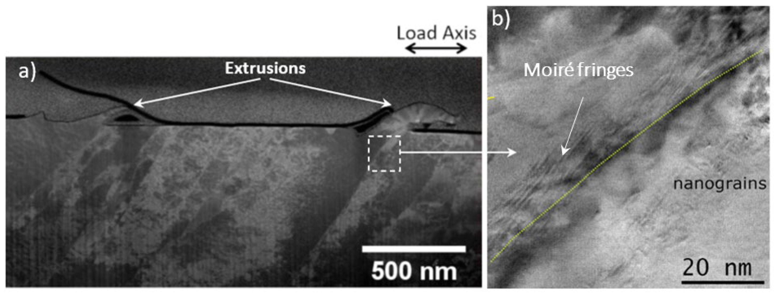
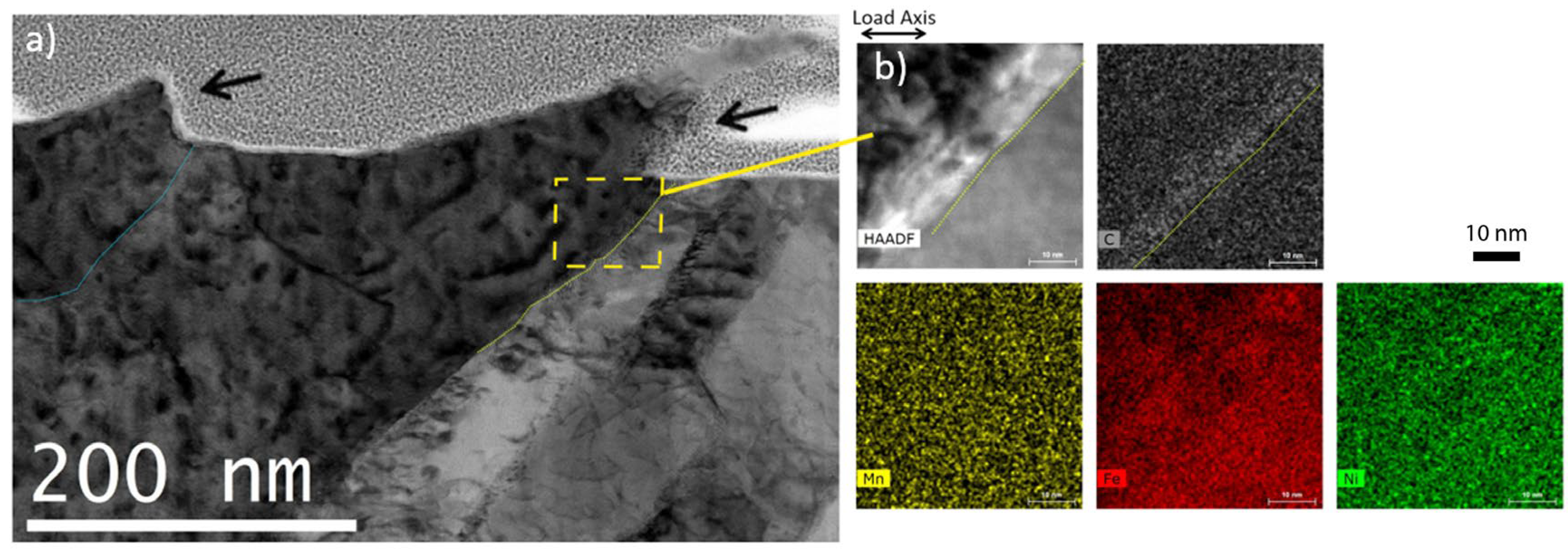
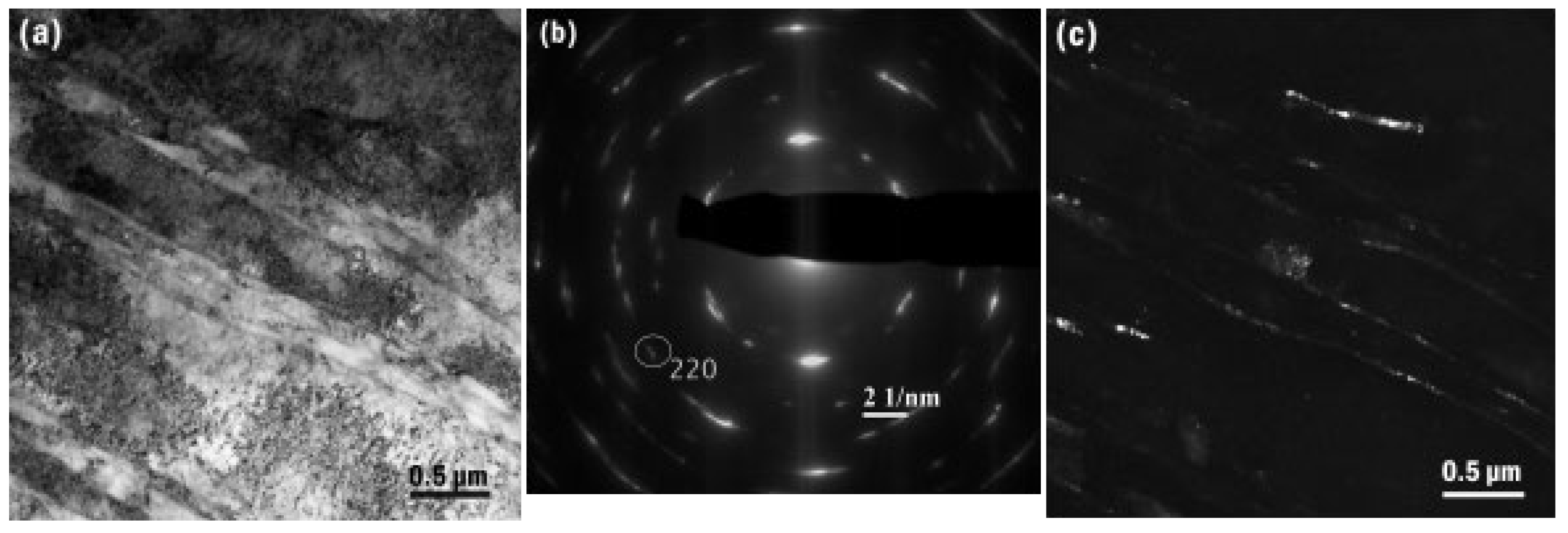
3.2. Link between Fatigue Etxrusion and Microstructure Revealed by TEM
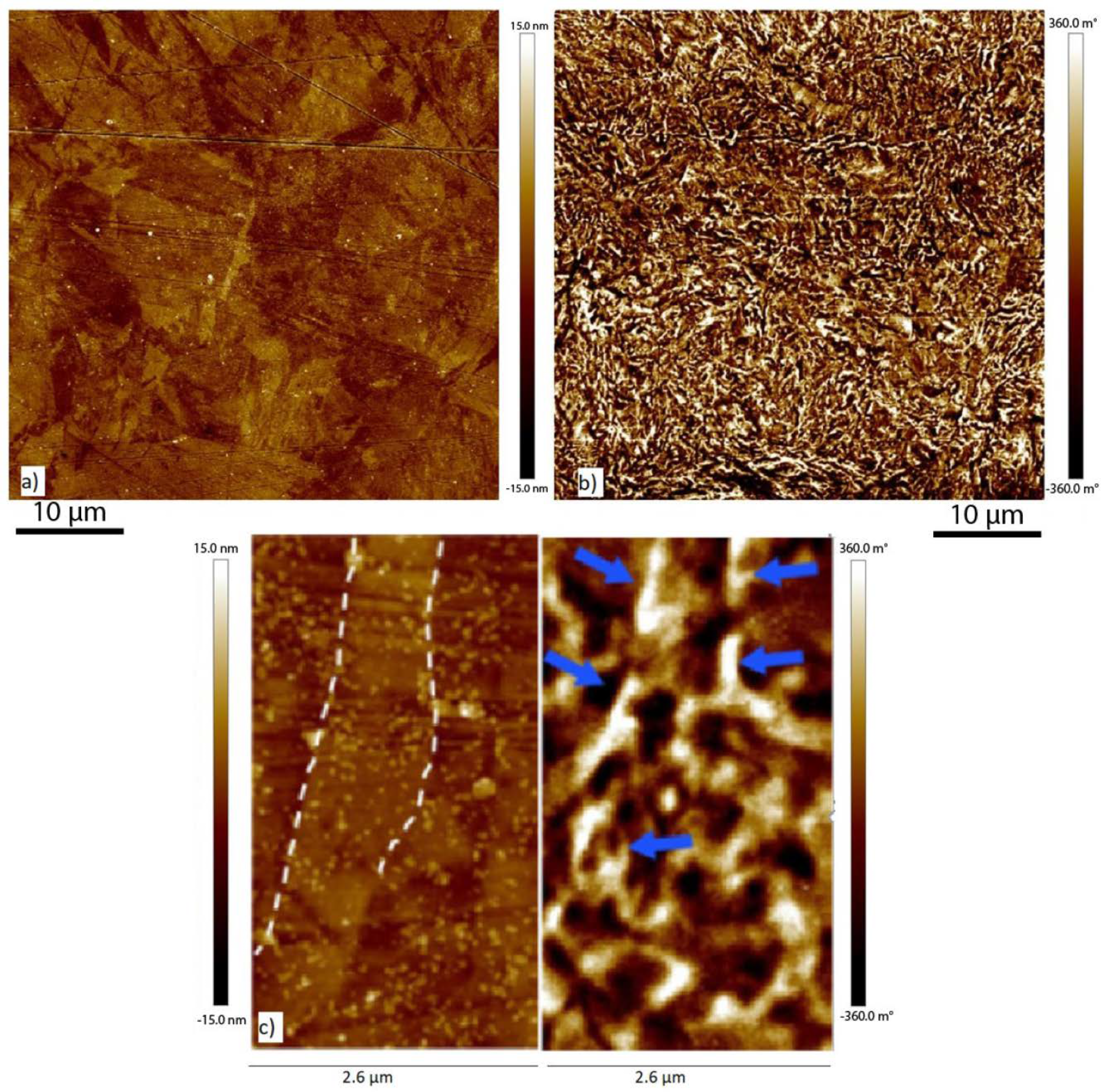
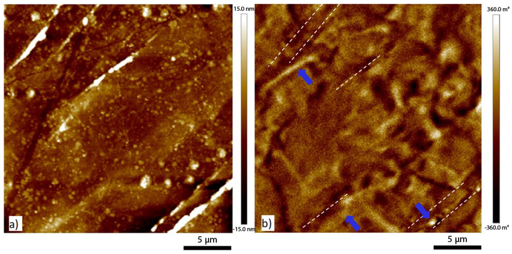
3.3. Clear Assesment of the Nature of Fatigue Extrusion and of the Link with Retained Austenite by MFM
4. Conclusions
Author Contributions
Funding
Institutional Review Board Statement
Informed Consent Statement
Data Availability Statement
Acknowledgments
Conflicts of Interest
References
- Laufer, E.E.; Roberts, W.N. Dislocations and persistent slip bands in fatigued copper. Philos. Mag. 1966, 14, 65–78. [Google Scholar] [CrossRef]
- Mecke, K.; Blochwitz, C. Internal displacements of persistent slip bands in cyclically deformed nickel single crystals. Phys. Status Solidi 1980, 61, K5. [Google Scholar] [CrossRef]
- Cheng, A.; Laird, C. Fatigue life behavior of copper single crystals. Part I: Observations of crack nucleation. Fat. Fract. Eng. Mater. 1981, 4, 331–341. [Google Scholar] [CrossRef]
- Brown, L.M. Dislocation substructures and the initiation of cracks by fatigue. Metal Sci. 1977, 11, 315–320. [Google Scholar] [CrossRef]
- Kim, W.H.; Laird, C. Crack nucleation and stage I propagation in high strain fatigue—II. Mechanism. Acta Metall. 1978, 26, 789–799. [Google Scholar] [CrossRef]
- Lukáš, P.; Kunz, L. Role of persistent slip bands in fatigue. Philos. Mag. 2004, 84, 317–330. [Google Scholar] [CrossRef]
- Piqueras, J.; Grosskreutz, J.C.; Frank, W. The influence of point-defect clusters on fatigue hardening of copper single crystals. Phys. Status Solidi 1972, 11, 567–580. [Google Scholar] [CrossRef]
- Lepistö, T.; Yli-Kauppila, J.; Kettunen, P.; Hautofärvi, P. Voids in fatigued copper single crystals. Phys. Status Solidi 1981, 67, K93–K97. [Google Scholar] [CrossRef]
- Polák, J. On the role of point defects in fatigue crack initiation. Mater. Sci. Eng. 1987, 92, 71–80. [Google Scholar] [CrossRef]
- Ho, H.S.; Risbet, M.; Feaugas, X.; Favergeon, J.; Moulin, G. Fundamental mechanisms of surface damage associated to the localization of the plastic deformation in fatigue. Proc. Eng. 2010, 2, 751–757. [Google Scholar] [CrossRef]
- Hu, Y.; Chen, Y.; He, C.; Liu, Y.; Wang, Q.; Wang, C. Bending Fatigue Behavior of 316L Stainless Steel up to Very High Cycle Fatigue Regime. Materials 2020, 13, 4820. [Google Scholar] [CrossRef]
- Salazar, D.; Serre, I.; Vogt, J.-B. LCF mechanisms of the 25Cr-7Ni-0.25N duplex stainless steel investigated by atomic force microscopy. In Proceedings of the Sixth International Conference on Low Cycle Fatigue (LCF 6), Berlin, Germany, 8–12 September 2008; DVM: Berlin, Germany, 2008; pp. 85–90. [Google Scholar]
- Ma, B.T.; Laird, C. Overview of fatigue behavior in copper single crystals—I. Surface morphology and stage I crack initiation sites for tests at constant strain amplitude. Acta Metall. 1989, 37, 325–336. [Google Scholar] [CrossRef]
- Basinski, Z.S.; Basinski, S.J. Low amplitude fatigue of copper single crystals–III. PSB sections. Acta Metall. 1985, 33, 1319–1327. [Google Scholar] [CrossRef]
- Höppel, H.; Goik, P.; Krechel, C.; Göken, M. Ex and in situ investigations on the role of persistent slip bands and grain boundaries in fatigue crack initiation. J. Mater. Res. 2017, 32, 4276–4286. [Google Scholar] [CrossRef]
- Man, J.; Vystavěl, T.; Weidner, A.; Kuběna, I.; Petrenec, M.; Kruml, T.; Polák, J. Study of cyclic strain localization and fatigue crack initiation using FIB technique. Int. J. Fatigue 2012, 39, 44–53. [Google Scholar] [CrossRef]
- Essmann, U.; Gösele, U.; Mughrabi, H. A model of extrusions and intrusions in fatigued metals I. Point-defect production and the growth of extrusions. Philos. Mag. A 1981, 44, 405–426. [Google Scholar] [CrossRef]
- Hunsche, A.; Neumann, P. Quantitative measurement of persistent slip band profiles and crack initiation. Acta Metall. 1986, 34, 207–217. [Google Scholar] [CrossRef]
- Polak, J.; Man, J. Mechanisms of extrusion and intrusion formation in fatigued crystalline materials. Mater. Sci. Eng. A 2014, 596, 15–24. [Google Scholar] [CrossRef]
- Polák, J. Role of Persistent Slip Bands and Persistent Slip Markings in Fatigue Crack Initiation in Polycrystals. Crystals 2023, 13, 220. [Google Scholar] [CrossRef]
- Polak, J.; Mazanova, V.; Heczko, M.; Kunena, I.; Man, J. Profiles of persistent slip markings and internal structure of underlying persistent slip bands. Fatigue Fract. Eng. Mater. Struct. 2017, 40, 1101–1116. [Google Scholar] [CrossRef]
- Krupp, U.; Giertler, A. Surface or Internal Fatigue Crack Initiation during VHCF of Tempered Martensitic and Bainitic Steels: Microstructure and Frequency/Strain Rate Dependency. Metals 2022, 12, 1815. [Google Scholar] [CrossRef]
- Wildeis, A.; Christ, H.-J.; Brandt, R. Influence of Residual Stresses on the Crack Initiation and Short Crack Propagation in a Martensitic Spring Steel. Metals 2022, 12, 1085. [Google Scholar] [CrossRef]
- Seidametova, G.; Vogt, J.-B.; Proriol Serre, I. The early stage of fatigue crack initiation in a 12%Cr martensitic steel. Int. J. Fatigue 2018, 106, 38–48. [Google Scholar] [CrossRef]
- Cota Araujo, M.A.; Vogt, J.-B.; Bouquerel, J. Retained austenite-aided cyclic plasticity of the quenched 9Ni steel. Int. J. Fatigue 2021, 152, 106445. [Google Scholar] [CrossRef]
- Maresca, F.; Kouznetsova, V.G.; Geers, M.G.D. On the role of interlath retained austenite in the deformation of lath martensite. Model. Simul. Mater. Sci. Eng. A 2014, 22, 045011. [Google Scholar] [CrossRef]
- Cullity, B.D. Elements of X-ray Diffraction; Addison-Wesley Publishing: Boston, MA, USA, 1956. [Google Scholar]
- Morito, S.; Oh-Shi, K.; Hono, T.; Ohba, T. Carbon enrichment in retained austenite films in low carbon lath martensite steel. ISIJ Int. 2011, 51, 1200–1202. [Google Scholar] [CrossRef]
- Zhang, Z.; Delagne, D.; Bernhard, G. Ageing effect on cyclic plasticity of a tempered martensitic steel. Int. J. Fatigue 2007, 29, 336–346. [Google Scholar] [CrossRef]
- Jürgens, M.; Olbricht, J.; Fedelich, B.; Skrotzki, B. Low Cycle Fatigue and Relaxation Performance of Ferritic–Martensitic Grade P92 Steel. Metals 2019, 9, 99. [Google Scholar] [CrossRef]
- Kanetani, K.; Moronaga, T.; Hara, T.; Ushioda, K. Deformation-Induced Martensitic Transformation Behavior of Retained Austenite during Rolling Contact in Carburized SAE4320 Steel. ISIJ Int. 2021, 61, 2629–2635. [Google Scholar] [CrossRef]
- Ke, X.; Zhang, M.; Zhao, K.; Su, D. Moiré fringe method via scanning transmission electron microscopy. Small Method 2022, 6, 2101040. [Google Scholar] [CrossRef]
- Fultz, B.; Kim, J.I.; Kim, Y.H.; Fior, G.O.; Morris, J.W. The stability of precipitated austenite and the toughness of 9Ni steel. Metall. Mater. Trans. A 1985, 16, 2237–2249. [Google Scholar] [CrossRef]
- Passeri, D.; Dong, C.; Reggente, M.; Angeloni, L.; Barteri, M.; Scaramuzzo, F.A.; De Angelis, F.; Marinelli, F.; Antonelli, F.; Rinaldi, F.; et al. Magnetic force microscopy: Quantitative issues in biomaterials. Biomatter 2014, 4, e29507. [Google Scholar] [CrossRef] [PubMed]
- Vokoun, D.; Samal, S.; Stachiv, I. Magnetic Force Microscopy in Physics and Biomedical Applications. Magnetochemistry 2022, 8, 42. [Google Scholar] [CrossRef]
- Gadelrab, K.R.; Li, G.; Chiesa, M.; Souier, T. Local characterization of austenite and ferrite phases in duplex stainless steel using MFM and nanoindentation. J. Mater. Res. 2012, 27, 1573–1579. [Google Scholar] [CrossRef]
- Zens, A.S.; Appel, T.; Broekaert, J.A.C.; Friedel, F. Determination of retained austenite in multiphase steels by magnetic force microscopy. Int. J. Mater. Res. 2006, 97, 1158–1162. [Google Scholar] [CrossRef]
- Shen, L.Q.; Luo, P.; Hu, Y.C.; Bai, H.Y.; Sun, Y.H.; Sun, B.A.; Liu, Y.H.; Wang, W.H. Shear-band affected zone revealed by magnetic domains in a ferromagnetic metallic glass. Nat. Commun. 2018, 9, 4414. [Google Scholar] [CrossRef]


Disclaimer/Publisher’s Note: The statements, opinions and data contained in all publications are solely those of the individual author(s) and contributor(s) and not of MDPI and/or the editor(s). MDPI and/or the editor(s) disclaim responsibility for any injury to people or property resulting from any ideas, methods, instructions or products referred to in the content. |
© 2023 by the authors. Licensee MDPI, Basel, Switzerland. This article is an open access article distributed under the terms and conditions of the Creative Commons Attribution (CC BY) license (https://creativecommons.org/licenses/by/4.0/).
Share and Cite
Cota Araujo, M.A.; Olive, J.-M.; Pecastaings, G.; Addad, A.; Bouquerel, J.; Vogt, J.-B. Compelling Evidence for the Role of Retained Austenite in the Formation of Low Cycle Fatigue Extrusions in a 9Ni Steel. Metals 2023, 13, 546. https://doi.org/10.3390/met13030546
Cota Araujo MA, Olive J-M, Pecastaings G, Addad A, Bouquerel J, Vogt J-B. Compelling Evidence for the Role of Retained Austenite in the Formation of Low Cycle Fatigue Extrusions in a 9Ni Steel. Metals. 2023; 13(3):546. https://doi.org/10.3390/met13030546
Chicago/Turabian StyleCota Araujo, Mahira A., Jean-Marc Olive, Gilles Pecastaings, Ahmed Addad, Jérémie Bouquerel, and Jean-Bernard Vogt. 2023. "Compelling Evidence for the Role of Retained Austenite in the Formation of Low Cycle Fatigue Extrusions in a 9Ni Steel" Metals 13, no. 3: 546. https://doi.org/10.3390/met13030546
APA StyleCota Araujo, M. A., Olive, J.-M., Pecastaings, G., Addad, A., Bouquerel, J., & Vogt, J.-B. (2023). Compelling Evidence for the Role of Retained Austenite in the Formation of Low Cycle Fatigue Extrusions in a 9Ni Steel. Metals, 13(3), 546. https://doi.org/10.3390/met13030546