Article

Study on Optimization of Nozzle Angle for Oxygen-Rich Side-Blown Lead Melting Furnace

1
State Key Laboratory of Refractories and Metallurgy, Wuhan University of Science and Technology, Wuhan 430081, China
2
Hubei Dajiang Environmental Protection Technology Co., Ltd., Huangshi 435005, China
*
Author to whom correspondence should be addressed.
Metals 2023, 13(3), 574; https://doi.org/10.3390/met13030574
Submission received: 8 February 2023 / Revised: 2 March 2023 / Accepted: 10 March 2023 / Published: 13 March 2023

Abstract

:
Taking an oxygen-rich side-blown lead melting furnace made by a company as the research object, the three-dimensional design software Solidworks was used to construct a model at an equal scale, and established a physical model which is in line with the actual system. Based on the determination of the physical properties of the slag phase and metal phase in the furnace, the VOF multiphase flow model and standard turbulence model in FLUENT were used to simulate the gas–liquid multiphase flow. By adjusting the different inclination angles of the spray gun, we analyzed the distribution changes of key indicators, such as the flow field, average turbulent kinetic energy and gas content in the furnace. At the same time, it was found that the turbulent kinetic energy in the middle of the furnace was large, which could strengthen the winding effect of the material and the best arrangement. The gas content of the upper part of the oxygen gun was high, and the gas content in the middle of the furnace was higher than that in the wall area on both sides and showed a gradual downward trend. If the inclination angle of the spray gun is too small, the agitation of the lower melting area is not strong enough, On the contrary, if the inclination angle is too large, the local flow rate of the sedimentation area increases and the gas content is low. The optimal tilt angle of the spray gun is between 10° and 15°.

1. Introduction

The oxygen-rich side-blowing smelting furnace is the key equipment of the oxygen side-blowing lead process. The melting process of the molten pool is to introduce oxygen-enriched air from both sides of the furnace body, and the Pb, Zn, Fe and other oxides stored in the form of sulfide will be oxidized into an oxide form under the oxidation atmosphere. The oxides, such as Zn and Fe, will enter the slag phase through the slagging reaction during the melting process, and the oxides, such as Pb, will be reduced to metal Pb through CO, C, etc. During the smelting process, oxides such as PbO are reduced into metal Pb by CO and C, or through the interaction reaction with residual PbS, PbSO4, and PbSO4, formed by peroxidation to form metal Pb. At the same time, a large amount of heat is released to achieve complete self-heating melting. High-speed oxygen-rich air pumped into the oxygen guns on both sides of the furnace enters the smelting zone and agitates the slag and matte. This is essentially a bubble-driven recirculating flow system. When the gas is released from the tuyere, it will form huge bubbles. Due to the differences of density, the bubbles tend to flow towards the top. During the process of flow rising, the melt flow is induced, and the flowing melt in turn affects the rising bubbles. This is a multiphase flow process. The study of flow process under different inclination angles can provide a reference for actual production and improve industrial production efficiency.
Many scholars have conducted related research on this process. Davis, et al. [1,2] conducted a simulation study on the flow and heat transfer phenomena in the molten reduction furnace under the action of the top-blown oxygen gun. Nazmul, et al. [3] carried out multiphase numerical simulation of the fluid flow in the reduction furnace and their study optimized different injection speeds and nozzle sizes. Valencia, et al. [4,5] carried out relevant research on the copper smelting converter through a numerical simulation and visualization experiment, and optimized the operating conditions of the copper smelting converter. Zhang, et al. [6] studied the flow state of bottom-blowing melting furnaces with different oxygen gun structures, and the results showed that the multilayer fence muzzle structure is helpful to strengthen the flow inside the molten pool. Li, et al. [7] took a bottom-blowing copper furnace in actual operation as the research object, established a three-dimensional numerical model, analyzed the gas–liquid two-phase flow law in the furnace, the velocity field of each phase in the furnace and the splashing mechanism of the melting furnace, and obtained the characteristics of each flow area in the furnace. Cai, et al. [8] used the water model and the VOF mathematical model to conduct experiments and numerical simulations on the submerged gas top-blowing stirred liquid phase fluids, respectively, and analyzed the deformation and movement of bubbles in the liquid phase and the flow field characteristics of liquid phase fluids under different injection conditions. Chen, et al. [9] simulated the solid–liquid flow process in the mechanical stirring zinc leaching tank by numerical simulation, and optimized parameters such as the blade bottom height and blade spacing. Yan, et al. [10,11] numerically simulated the gas–liquid two-phase flow in a reduction furnace with a high lead slag, and obtained the optimal operating conditions of the furnace. Many researchers have devoted themselves to the study of gas–liquid multiphase flow in metallurgical smelting [12,13,14,15,16,17,18,19,20]. They also realized that accurate results can be obtained by using transient three-dimensional models.
In industrial practice, most of the above researches focus on the oxygen-rich bottom-blowing furnace, and there are few related researches on the oxygen-rich side-blowing furnace. This paper took the oxygen-rich side-blowing furnace of a certain company as the research object, established a suitable gas–slag–lead matte multiphase flow model, simulated the basic state of gas–liquid flow under different working conditions and found out the most suitable working conditions for industrial production to provide theoretical basis for the actual industrial production.

2. Model Building

2.1. Geometric Model

The oxygen-rich side-blowing furnace studied in this paper was constructed by 3D CAD software Slidworks2020 (Slidworks, MA, USA) with an equal scale size 1:1, as shown in Figure 1.
The oxygen-rich side-blown furnace is mainly composed of three parts: the deposition zone, melting zone and flue gas zone. There are two groups of oxygen guns on both sides of the smelting zone, 12 on each side, and each side is evenly distributed. The length of the side-blowing furnace is 4.5 m, the spacing of each oxygen gun is 346 mm, and the caliber of the oxygen gun is 75 mm. The deposition area of the side-blowing furnace is 1.08 m wide and 0.8 m high; the melting zone is 1.8 m high, and the side of the melting zone is 7° from the side of the deposition zone. The smoke zone is 3 m high. To sum up, the simple introduction of the oxygen-rich side-blowing furnace is as follows:
  • Ignore the flue gas recovery device of the furnace top feeding device and exhaust outlet.
  • Due to the complex structure of the oxygen gun, it is simplified to open holes on the wall, which is in order to improve the mesh accuracy and computing efficiency.
  • Since the oxygen-rich side-blown furnace is in a symmetrical structure, it has taken a quarter of its structure as the computing domain and divided into grids in order to save computing resources and improve computing efficiency.

2.2. Mathematical Model

2.2.1. VOF Model

The flow of the fluid in the oxygen-rich side-blowing furnace is a typical multiphase flow process. The numerical simulation methods of multiphase flow are mainly divided into two types: the Euler–Lagrange method and the Euler–Euler method. In ANSYS FLUENT2021R1, VOF, Mixture and Eulerian can be used for the calculation of the Euler–Euler method. The VOF model in the Euler–Euler method is a surface tracer method fixed under Euler mesh. When studying the interface of various non-melting fluids, we often applied this model. In the VOF model, different components share a set of momentum equations, and the volume rate of each fluid component is recorded in each calculation unit in the whole flow field during calculation. VOF model is selected due to the obvious phase interface between different phases studied in this paper. The basic governing equation describing the VOF multiphase flow model is as follows:
(1)
Volume fraction equation [21,22]
The volume fraction equation of gas phase and slag phase is:
  t α g ρ g + · α g α g v = 0
t α s ρ s + · α s ρ s v = 0
The volume fraction of lead bullion phase is:
α l = 1 α g α s
where α g , α s and α l is the volume fraction of the gas phase, slag phase and lead bullion phase; ρ g and   ρ s is the density of gas phase and slag phase (kg/m3); v is the moving speed (m/s).
(2)
Momentum equation
When a single momentum equation is solved in the whole computational domain, the resulting velocity field is shared by all. The equation is:
t ρ v + · ρ v v = p + μ v + v T + ρ g + F
where, ρ is the mixing density (kg/m3); v is the speed (m/s); g is the acceleration of gravity; p is the pressure (Pa); μ is effective viscosity (Pa· s ) ; v T is the speed transpose matrix; F is the source item.
The calculation formula of ρ and μ is as follows:
ρ = α g ρ g + α s ρ s + α l ρ l
μ = α g μ g + α s μ s + α l μ l  
where, ρ l is the lead bullion density/(kg·m−3); μ g ,   μ s   and   μ l   is the viscosity of gas phase, slag phase and lead bullion phase (Pa· s ) .
The VOF model can include the influence of surface tension along each pair of phases. The additional surface tension in the calculation results in the source term of the momentum equation. The surface tension can be written according to the pressure jumping across the surface. The surface force can be expressed as the volume force using the divergence theorem. It is this volume force that becomes the source term added to the momentum equation. Its form is as follows:
  F = P a i r s   p q , p < q σ p q   α p ρ p k q α q + α q ρ q k p α p 1 2 ρ p + ρ q
where,   σ p q is the surface tension coefficient; α p ( α q ) is the gradient of the volume fraction of phase p(q); k p ( k q ) is the surface curvature of p(q) phase; ρ p ( ρ q ) is the p(q) phase density.
Lead bullion and slag are stable and incompressible liquids. Because the compressibility of the gas phase can be ignored when the flow rate is not high in engineering, it is treated as an incompressible fluid. The governing equation of the incompressible ideal gas model is as follows:
ρ g = p O P R M W T  
where, p O P is the operating pressure (Pa); R is the ideal gas constant; M W is the molecular weight of the gas.

2.2.2. Turbulence Model

The problem of the multiphase flow needs to be solved by the turbulence model, and the k-ε model has been widely used in industrial simulation. The standard k-ε turbulence model adopted in this paper is a semi-empirical formula whose governing equations are composed of the turbulent kinetic energy k equation and eddy dissipation rate ε equation.
The turbulent kinetic energy k equation describing the turbulence model is:
t ρ k + · ρ v k = · μ + μ t σ k k + G k ρ ε  
where, k is the turbulent kinetic energy(m2/s2); μ t is turbulent viscosity (Pa· s ) ; ε is the dissipation rate(m2/s3); σ k is the turbulent Prandt number of k, which is generally 1; G k   is turbulent kinetic energy generated by laminar velocity gradient.
The ε equation describing the vortex dissipation rate of the turbulence model is:
  t ρ ε + · ρ v ε = · μ + μ t σ ε ε + C 1 ε   G k ε k C 2 ε   ρ   ε 2 k  
The calculation formula of A is as follows:
μ t = ρ C μ k 2 ε
where, σ ε   is the turbulent Prandt number of ε, which is generally 1.3, C is a constant and is 1.44, C is a constant and is 1.92; C μ is a constant and is 0.09.
For the side-blown smelting process, the standard k-ε turbulence model and RNG k-ε turbulence models can simulate such flows. However, the calculation time of the RNG k-ε turbulence model is longer. In order to reduce the calculation time, this paper selects the standard k-ε turbulence model. Due to the complex reaction in the melting zone, this paper mainly studies the flow process of the fluid in the furnace without considering the chemical reaction. The temperature in the furnace is uniform during initialization, ignoring the influence of temperature on the gas phase, and the energy equation is not opened.

3. Physical Parameters, Boundary Conditions and Solution Settings

3.1. Physical Parameters

In the simulation of multiphase flow in the oxygen-rich side-blowing furnace, the physical parameters of the fluid are of great importance to the flow of each phase fluid, the generation and bursting of bubbles, etc. In this paper, the original model has two rows of 24 entrances, which are symmetrically distributed. A high temperature physical property tester was used to measure the density, viscosity and other physical parameters. The temperature in the melting zone is approximately 1200 °C, the temperature in the deposition zone is approximately 950 °C and the temperature in the melting zone is approximately 950 °C. Therefore, in the process of measuring its physical parameters, the sample was first melted and raised to the specified temperature, and its density, viscosity and other physical parameters were measured at the specified temperature. The results are shown in Table 1.

3.2. Boundary Conditions and Solution Settings
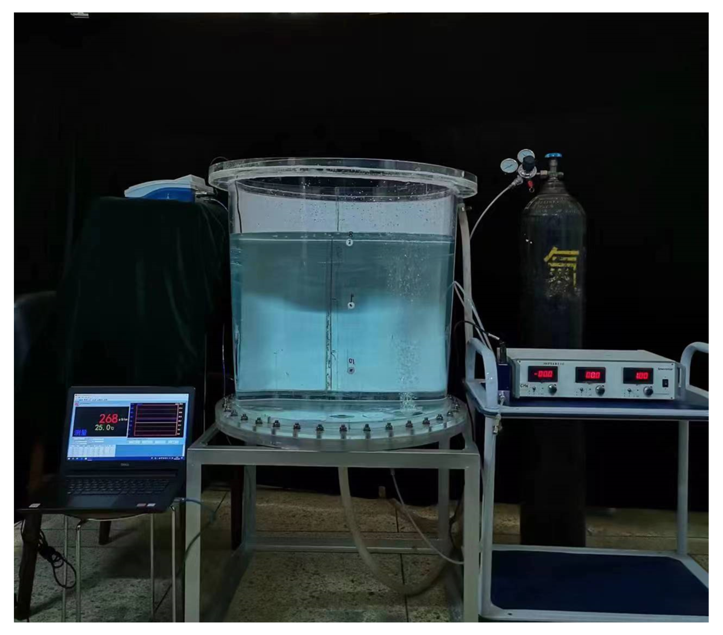
The original model has two rows of 24 entrances, which are symmetrically distributed. In order to save computing resources, a quarter of the original model was chosen as the computing object, the grid was approximately 670,000 and there were six velocity inlet boundaries. The initial speed of inlet air is 18 m/s. The turbulence intensity is 3.2%. The two sides were set as symmetric boundary conditions, the upper end as pressure outlet boundary conditions and the outlet gauge pressure was zero. Other walls are insulated. For the flow near the wall, the standard wall function method is used, and the velocity at the wall is zero. The remaining surfaces are wall surfaces. The standard wall function method is used for the flow in the near wall region. The residual of each governing equation converges to 10−4. The SIMPLE algorithm is used for the coupling of pressure and velocity, and the second order upwind scheme was used for momentum equation. Based on the VOF model and the standard κ-ε model, the minimum time step is 0.001 s. The model adopted the transient simulation, and the total operation time of the oxygen-rich side-blowing lead melting furnace is 16 s. The simplified initial component state is shown in the Figure 2.

4. Model Validation

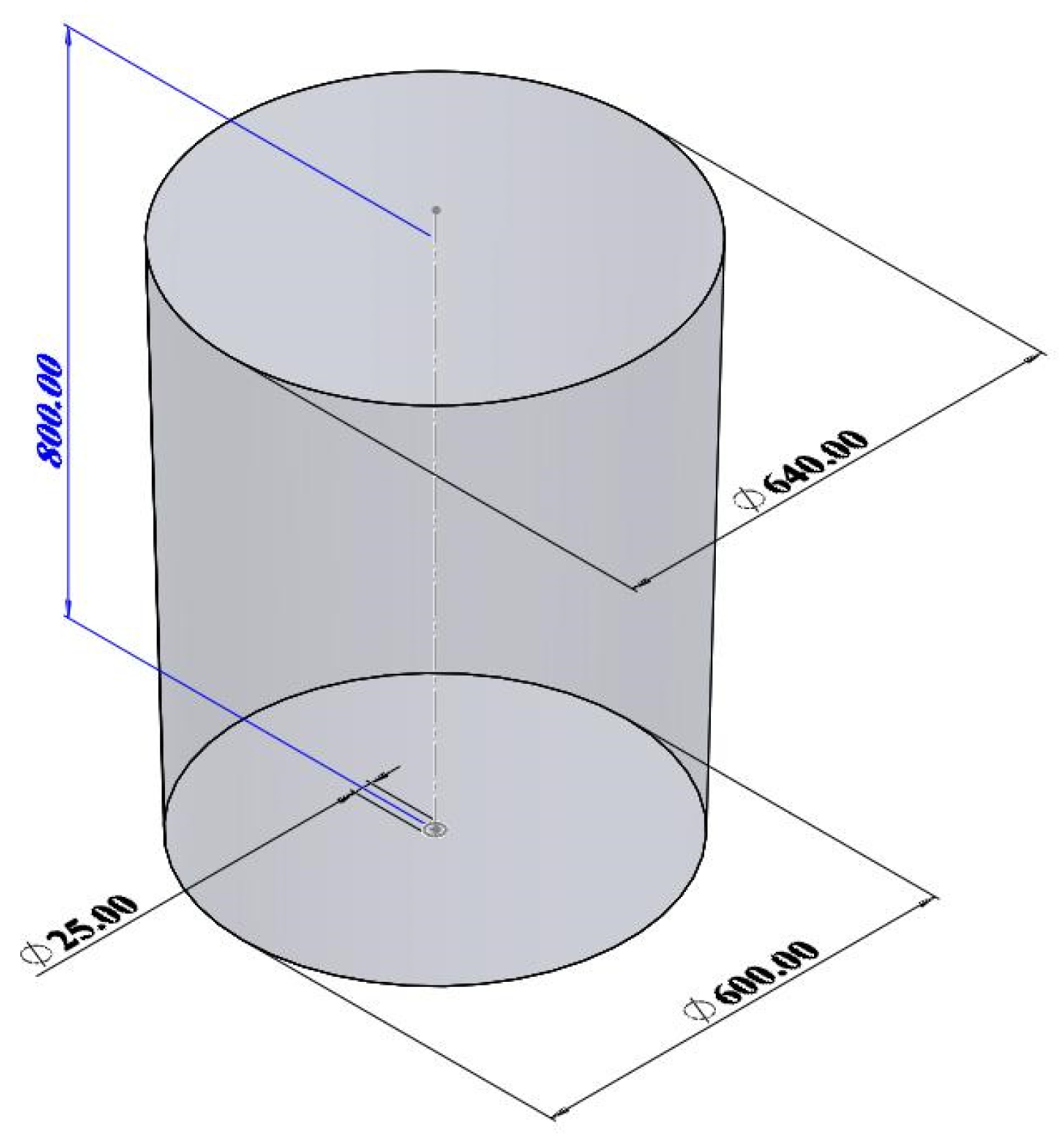
4.1. Geometric Structure and Physical Parameters

Due to the complex structure of the oxygen-enriched side-blowing furnace, it is difficult to build a hydraulic model. Therefore, this paper constructs a 1:1 geometric model (Figure 3) through a simple ladle hydraulic model (Figure 4). At room temperature, the air–water–oil three-phase system replaces the oxygen-enriched air–slag–lead bullion three-phase system. Measure the relevant physical property parameters and set the inlet injection flow to 7.5 L/min using the same mathematical model to verify the applicability of the mathematical model.
Theladle geometric parameters and physical parameters of water model are shown in Table 2 and Table 3.

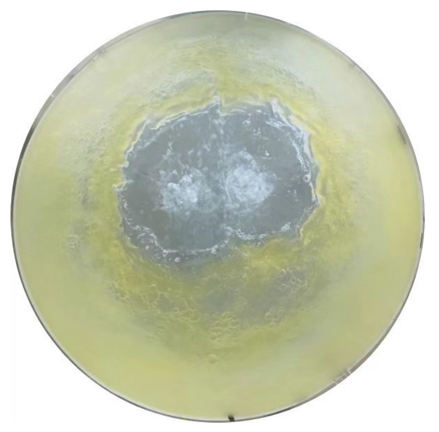
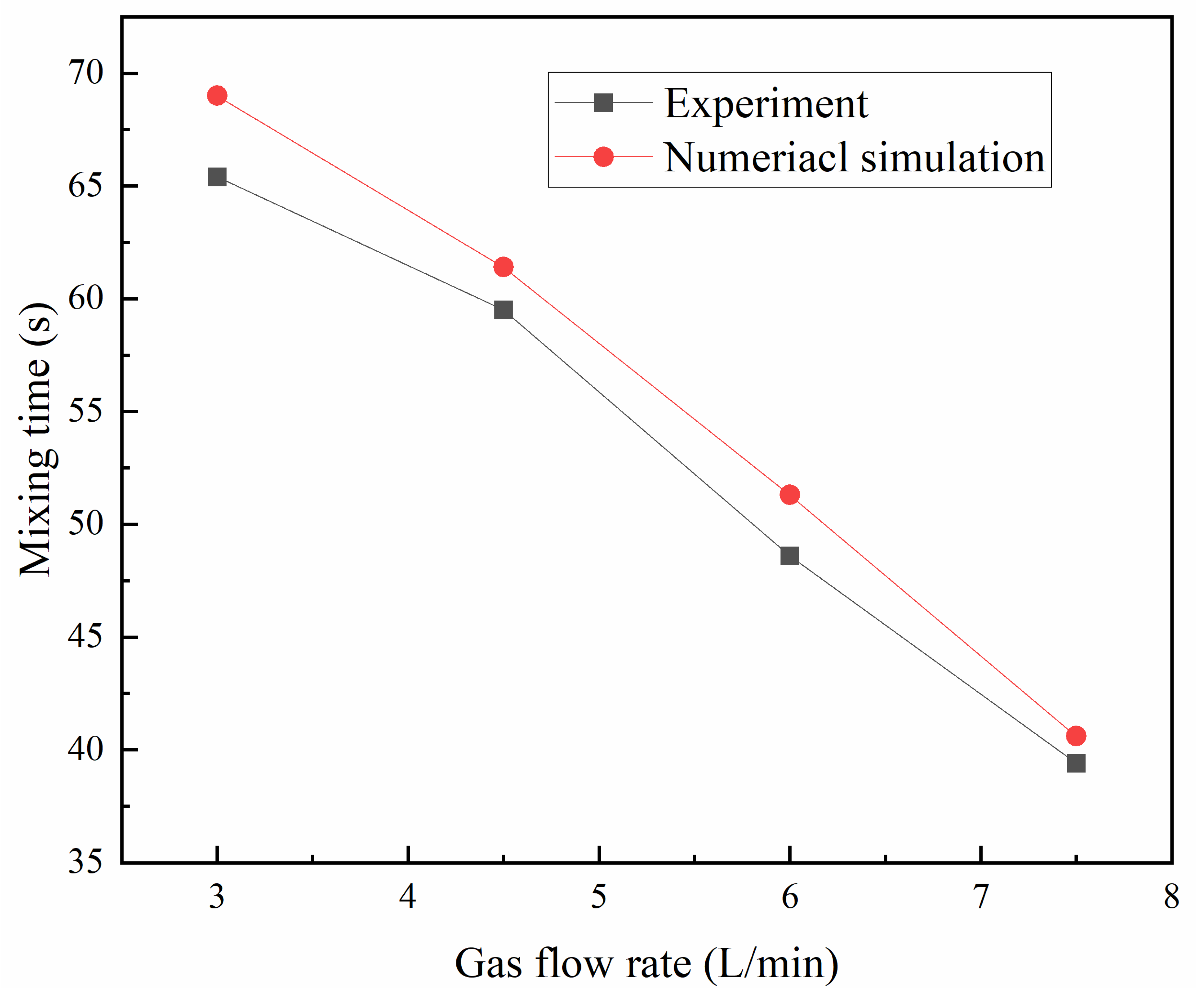
4.2. Component Nephogram and Mixing Time Verification

As shown in Figure 5 and Figure 6, the oil distribution image and the simulated component cloud diagram of the upper interface of the hydraulic model and the numerical model are, respectively, in a relatively stable state.
The comparison of the two groups of images shows that the oil distribution at the upper interface is similar in shape, both of which are irregular ellipses, slightly deviating from the central area. After measurement, the area percentage of water in the oil distribution image is 23.7%, while the area percentage of water in the oil composition cloud image is 25.8%. The error between the two is 8.1%. Due to some error in the experimental measurement, the difference between the two is within the allowable range. The result proves the correctness of the mathematical model.
By further setting different inlet flows, the mixing time in the molten pool is measured, and the experimental results are compared with the simulation results, as shown in Figure 7. In the process of the numerical simulation, the monitoring point is set corresponding to the measuring position of the conductivity meter in the physical simulation experiment, and the tracer is added at the same position in the water model experiment. The mixing time in the reactor is determined by observing the change of the tracer concentration at the monitoring point.
The results show that the mixing time increases with the decrease of the injection flow. The difference of mixing time between the experimental measurement results and the numerical simulation results under different inlet flow rates is small, and the error is less than 5.3%. This result further proves the correctness and feasibility of the mathematical model.

5. Result Analysis

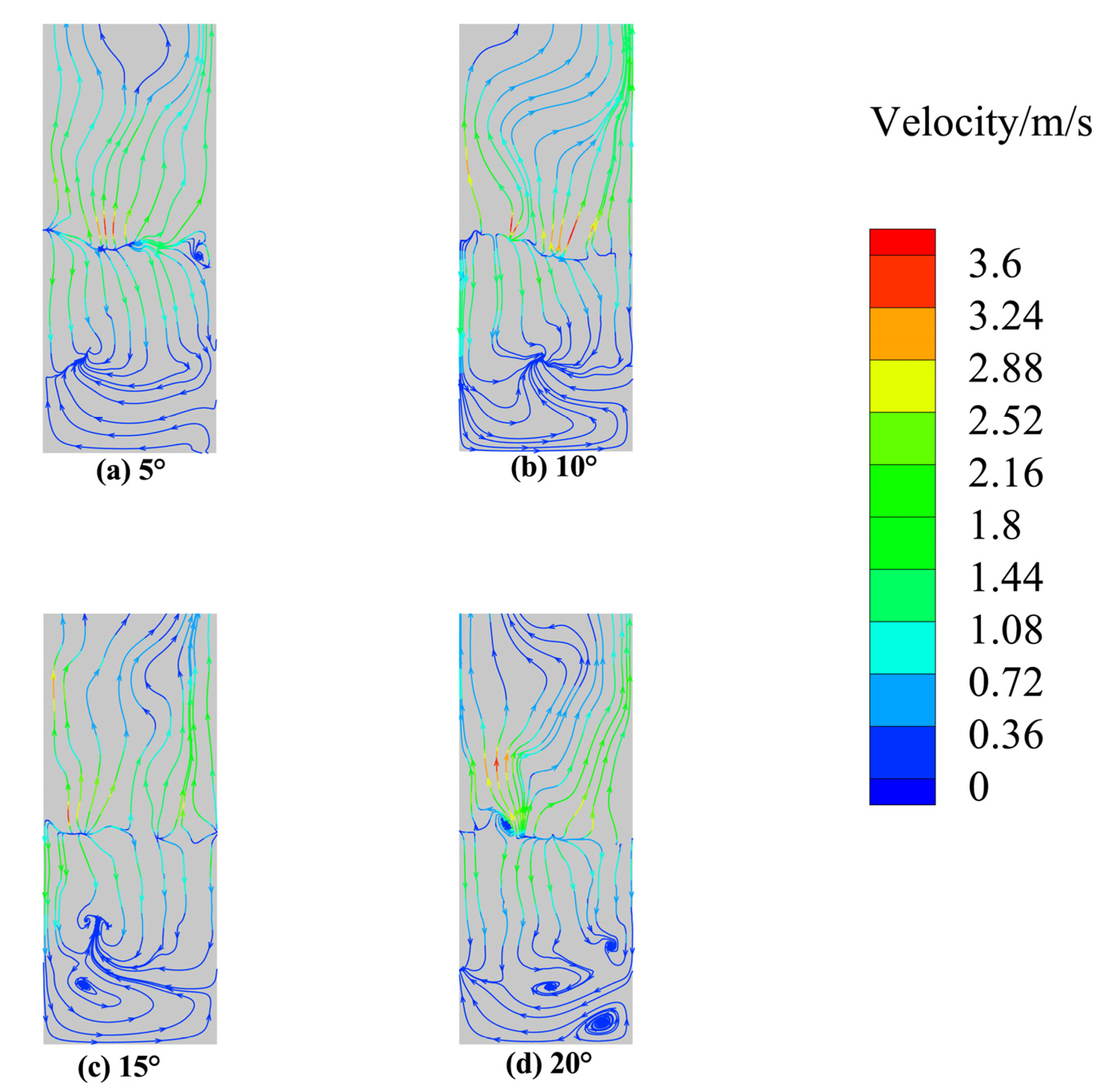
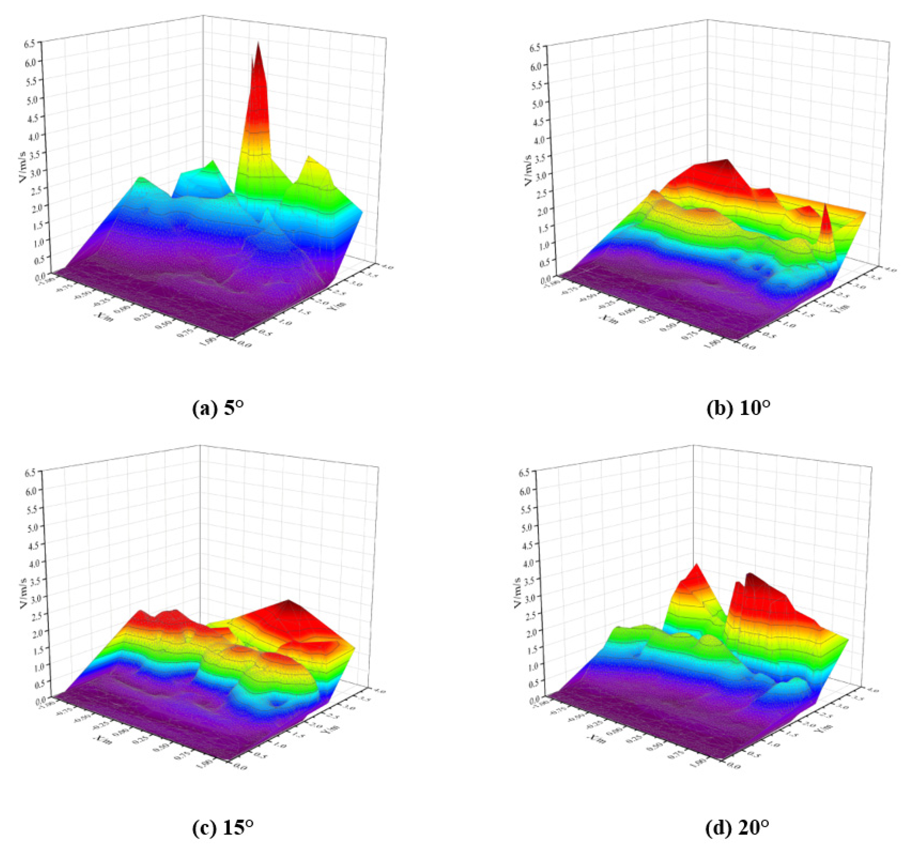
5.1. Flow Field Analysis with Different Angles

The flow field distribution of each section in the melting zone and the deposition zone has a great influence on the completeness of the reaction and the quality of the product precipitation. Figure 8 shows the flow field distribution diagram at the typical section with different angles.
When the gas enters the smelting zone, the gas interacts with the melt, and the kinetic energy of the gas is transformed into the kinetic energy of the melt, and the melt moves in the circulation. Owing to the influence of the circulation, the overall velocity of the smelting zone is larger, and the strong agitation is conducive to the collision and condensation of the lead droplets. Meanwhile, it can also reduce the dissolution of the lead matte in the smelting zone and strengthen the diffusion of the refractory components. As can be seen from the figure, the gas flow field is upward, and the melt is mainly downward, with a high velocity above and low velocity below. The lower fluid flows from both sides to the middle, and there is vorticity in the smelting zone. Such vorticity is conducive to strengthening the coiling effect of materials, the stirring effect in the smelting zone and the continuous REDOX chemical reaction in the smelting zone. With the increasing tilt angle of the spray gun, the vortex began to move downward and the velocity underneath became larger. When the dip angle was 5°, the velocity of the flow field near the deposition area was small, which is not conducive to the full progress of the reaction. When the angle of the spray gun increased to 10°, a large reflux center appeared near the deposition area in the smelting area, which is beneficial to the mixing of materials in the smelting area and can speed up the reaction. When the dip angle continued to increase to 15°, the reflux center moved downward and split into two small vortices. When the dip angle increased to 20°, the disturbance to the deposition area was more intense, and the large reflux center continued to move down to the deposition area, finally turning into four smaller vortices. The flow field in the deposition area was not stable enough, and the deposition process became disorderly, which was not conducive to the sedimentation and separation of lead matte.
Figure 9 shows the velocity distribution of the Z = 0 section at different angles. It can be seen from the figure that the velocity at the interface between the melting zone and the flue gas zone is relatively high, because the upper pressure decreases with the increase of the height of the bubble in the process of rising, and the buoyance force is greater than gravity and the pressure. The bubble accelerates and reaches at the interface with a higher speed. When the inclination angle of the spray gun is 5°, the maximum flow velocity of the fluid is 6.34 m/s. With the increase of the spray angle, the overall flow velocity of the section moved downward. With the increase of the spray angle, the partial velocity of the gas in the horizontal direction decreases, while the partial velocity in the longitudinal direction increases, and the stirring of the smelting zone in the lower part of the spray gun is more uniform. Therefore, there will be no large difference in the local flow velocity and chaotic distribution. The overall average velocity in the smelting zone of 10~15° is larger, which is conducive to the smelting reaction. When the spray gun angle continues to increase to 20°, the overall average velocity in the upper smelting zone decreases, and the agitation of the chemical reaction in the smelting zone is not strong enough.
In summary, from the distribution of the cross-section flow field and cross-section velocity field, the angle of the spray gun was too small, the agitation in the lower smelting zone was not strong enough and the overall flow rate was not uniform. Moreover, the angle was too large, and the local flow rate in the deposition area increased, which were not conducive to the stable separation of lead matte, so the spray gun angle of 10°~15° is more suitable.

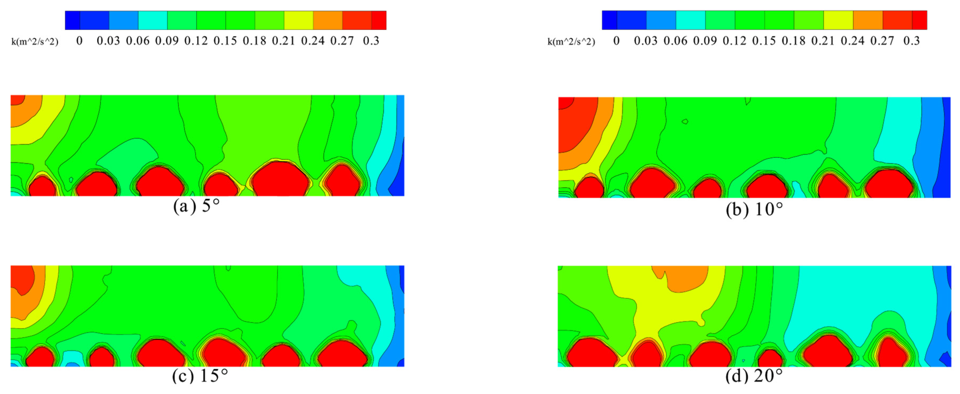
5.2. Analysis of Turbulent Kinetic Energy with Different Dip Angles

Figure 10 shows the cloud diagram distribution of turbulent kinetic energy at the section of Y = 1.1 m melting zone, which is the section of the oxygen gun nozzle. It can be witnessed from the figure that the turbulent kinetic energy at the outlet of the oxygen gun is obviously greater than that at other locations, and the turbulent kinetic energy is centered on the nozzle of the oxygen gun and spreads around in a ring. There is a huge velocity difference and density difference between the gas and the melt in the melting zone, and gas impaction through the melt requires a large amount of kinetic energy. In a small area, the turbulent kinetic energy of the oxygen-rich gas decreases rapidly, while the turbulent kinetic energy of the nearby melt increases and is transferred to the adjacent melt, which is also one of the reasons for the formation of the turbulent flow. Under different angles, the left side of the cloud image is close to the middle of the oxygen-rich side-blown furnace, and the overall turbulent kinetic energy is greater than that of other areas, indicating that the fluid flow in the middle of the furnace is more intense under this distributed oxygen gun arrangement structure. Therefore, in the process of releasing reaction materials, the feeding port can be set as the middle of the upper outlet of the side-blown furnace, which is conducive to the rapid coiling of the materials by fluids and from the middle to the periphery of the rapid diffusion to speed up the smelting zone of various chemical reactions. It can be seen from the figure that the turbulent kinetic energy of the section is larger and more uniform when the angle of the spray gun is small. This is because when the angle of the spray gun is small, the transverse flow velocity of the inlet gas is large and the inlet gas of the oxygen gun on both sides and the melt in the melting zone interact fully on the transverse section. With a spray gun angle of 5°, 10° and 15°, there is little difference in the distribution of turbulent kinetic energy. There is a small amount of dead zone. When the angle of the spray gun increases to 20°, the transverse gas velocity is small and the longitudinal velocity increases, resulting in insufficient stirring of the transverse section. The turbulent kinetic energy in the center decreases and transfers to both sides, and the range of the small turbulent kinetic energy in the right wall area obviously increases, resulting in the increase of the range of the dead zone. It was not conducive to the full REDOX reaction in the smelting zone and affected the deposition of the lead matte.

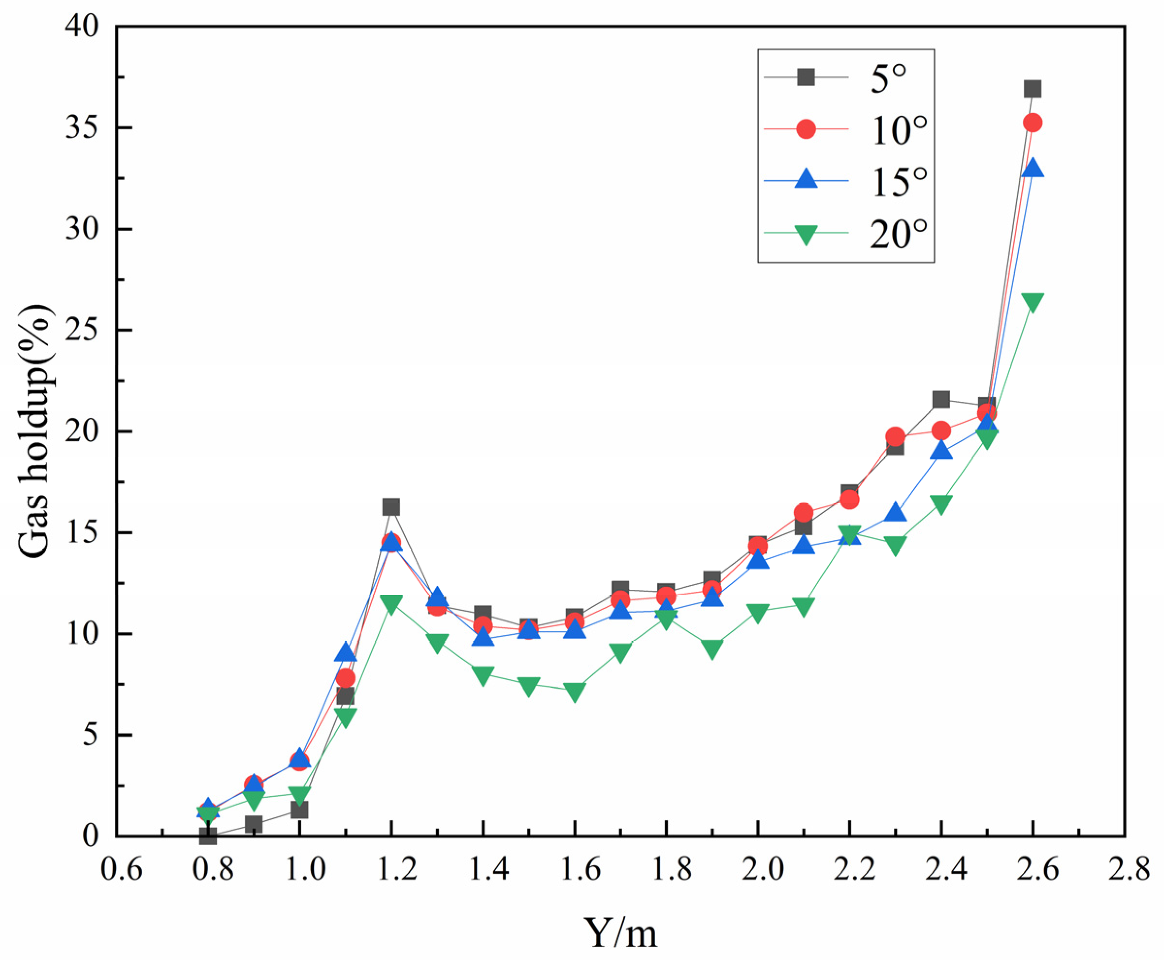
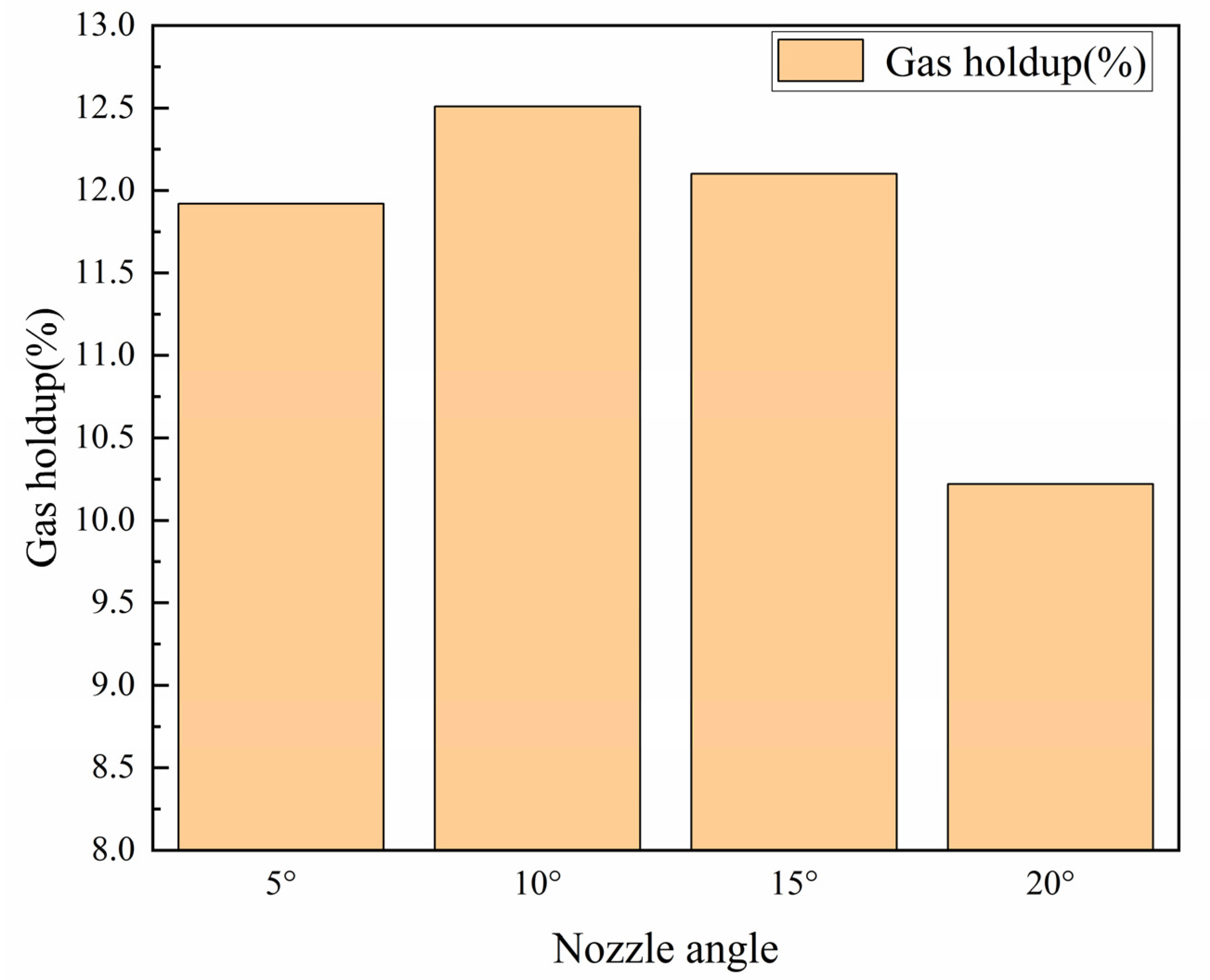
5.3. Gas Holdup Analysis of Different Dip Angles

The distribution of the gas holdup in the smelting zone is an important index in the smelting process of the oxygen-rich side-blown furnace. The oxygen-rich gas has two main functions. On the one hand, as a reaction gas, it participates in the REDOX reaction of sulfide and the oxidation of low-cost oxides, etc. On the other hand, the high-speed oxygen-rich air provides power for the melt in the smelting zone, which keeps the melt in a strong stirring state. By analyzing its distribution, we can find out the high efficiency reaction interval in the smelting process, improve the smelting efficiency in the smelting zone, improve the metal yield and reduce the production of by-products. In order to further understand the gas holdup distribution of the reaction zone in the melting furnace during the reaction process, the gas holdup of different sections in the melting zone in the furnace is taken as the analysis object. The results are shown in Figure 11 and Figure 12.
Taking a 5° dip angle as an example, it can be seen from Figure 11 that the gas holdup is very low and tends toward zero within the range of 800~900 mm depth of the side-blowing furnace. With the increase in height, the gas holdup of the section begins to rise. A wave peak is generated at a height of 1200 mm, and the gas holdup reaches its peak within a short vertical height. The reason is that the nozzle of the spray gun is located at a height of 1100 mm, the density of oxygen-rich gas is far less than that of the melt and the overall bubble has a rising trend near the top of the nozzle. Therefore, a large number of bubbles gather in a short time and the gas holdup increases significantly and rapidly. With the increase in height, in the lower part of the melting zone, the bubbles are mainly in the deformation stage and the rising speed is small, the probability of fusion and breakage among the bubbles is very small and each bubble basically exists in a separate form. At the same time, the cross-sectional area of the side-blowing furnace melting zone increases, and the cross-sectional gas holdup has a slow decline process. When the height reaches 1500 mm, with the increase in height, the pressure on the bubble gradually decreases, the bubble rising speed increases and the probability of the breakage and fusion between adjacent bubbles increases, which will produce many small bubbles and disperse in the surrounding melt. Therefore, with the further increase of the section height, this breakage and fusion effect begins to play a major role. The gas holdup of the section began to increase steadily.
The changing trends of the overall gas holdup of the vertical section are similar under different spray gun inclination angles. When the angle of the spray gun is 5°, the gas holdup in the melting area near the deposition area is the smallest, while the gas holdup in the area near the spray gun is the largest. This is because when the angle of the spray gun is small, the transverse flow velocity of oxygen-rich gas is larger, while the longitudinal flow velocity is smaller. Therefore, the gas holdup in the lower part of the melting area near the deposition area is lower. However, near the oxygen gun, the gas holdup was higher, and the minimum and maximum gas holdup appeared at 5° inclination angle. The gas holdup distribution was uneven in each area, and the difference was large. This gas holdup distribution was not conducive to the full progress of REDOX reaction, and the byproduct impurity rate would increase, resulting in the decrease of lead matte production. When the dip angle increases to 10°, the gas longitudinal injection depth increases, the gas holdup in the lower part of the melting zone is larger, the gas residence time in the melting zone increases, the bubbles can be dispersed better in the molten pool and the peak gas holdup is larger. The gas holdup distribution in the upper part of the oxygen gun nozzle in the melting zone is similar to that of the 5° dip angle, and the overall gas holdup is more uniform. The distribution is conducive to the full progress of the REDOX reaction in the smelting zone. When the dip angle increases to 15°, the overall gas holdup distribution is similar to that of 10°, and the gas holdup at the upper part of the molten pool is slightly less than 10°. When the dip angle continues to increase to 20°, the gas holdup size of different sections is significantly lower than the gas holdup distribution size of 10° and 15°. The reason is that the large tilt angle contributed to the small transverse kinetic energy of the gas, the gas content in the middle of the molten pool is too small, and it is mainly distributed near the wall of the furnace lining. In addition, the oxygen-rich gas cannot be evenly dispersed in the melting zone, which resulted in the overall gas holdup being small.
Figure 12 shows the gas holdup distribution of the different X-axis sections at the different angles of the spray gun. It can be seen from the figure that the gas holdup at different angles presents a zigzagged distribution, which is related to the distribution position of the spray gun. The section near the spray gun has a significantly higher gas holdup. From the overall gas holdup distribution trend, the gas holdup tends to decrease from left to right. The gas holdup near the middle of the molten pool is higher, while the gas holdup near the walls on both sides of the molten pool is lower. Compared with the different angles of the spray gun, the maximum atmospheric holdup value appears at the position near the middle of the molten pool at an angle of 10°, and the minimum value appears at the position near the two sides of the wall at an angle of 20°. At the same section, the overall gas holdup of the 10° and 15° dip angles is larger than the 5° and 20° dip angles.
Through Figure 11 and Figure 12, we entirely analyzed the gas holdup distribution law of different sections from different dip angles. The gas holdup distribution state of different sections was affected by various factors. By investigating the change of the gas holdup in the whole melting zone at different angles, we can intuitively analyze the whole and find out the best melting conditions, as shown in Figure 13.
As can be seen from Figure 13, with the increase of the spray gun angle, the overall gas holdup in the smelting area presents a trend of first increasing and then decreasing. With the increase of the spray gun angle, the residence time of oxygen-rich air in the melting zone increases, the bubbles can be better dispersed in the melting zone, and the gas holdup increases. With the further increase of the dip angle, the transverse kinetic energy of the gas decreases, and the probability of collision with most of the melt in the middle of the melting zone decreases, the gas holdup in the middle of the molten pool decreases and the bubble distribution migrates to both sides of the wall, resulting in the overall gas holdup in the melting zone decreasing.
In conclusion, when the spray gun tilt angle is 10°–15°, the gas holdup in the smelting zone is higher, the gas holdup distribution in each section of the smelting zone is more conducive to the flow of the molten pool and the full progress of various chemical reactions. At the same time, it can also reduce the production of byproducts and improve the yield of lead matte. Therefore, a spray gun tilt angle of 10°–15° is the best.

6. Conclusions

  • Through the analysis of the size distribution of turbulent kinetic energy in the section, it is found that under a uniformly distributed oxygen gun arrangement structure, the turbulent kinetic energy in the middle of the furnace is the largest, which is conducive to strengthening the coiling effect of materials, and the middle position above the furnace is the best material inlet.
  • Through the analysis of the gas holdup of different sections, it is discovered that the gas holdup near the upper part of the oxygen gun is higher, the gas holdup in the middle of the furnace is higher than that in the near wall area on both sides and that it gradually decreases to both sides.
  • Through the comparative analysis of the flow field, turbulent kinetic energy and gas holdup of each section under the different angles of the spray gun, the appropriate angle of the spray gun can improve the gas holdup in the melting zone and strengthen the flow of fluid in the molten pool. It is such a situation that can motivate the full progress of various chemical reactions and reduce the generation of by-products. The optimal angle of the spray gun is between 10° and 15°.

Author Contributions

Methodology, Z.J.; Writing-original draft, X.W.; Investigation, Q.Q.; Writing-review and editing, Z.Y.; Resources, R.C.; Project administration, H.T. All authors have read and agreed to the published version of the manuscript.

Funding

Science and technology projects of Hubei Province (2020BED026); Hubei special (second batch) project of special action for scientific and technological personnel serving enterprises in 2020.

Data Availability Statement

Exclude this statement.

Conflicts of Interest

The authors declare no conflict of interest.

References

  1. Mark, P.; Schwarz, M.P. Flow simulation of the hismelt process. In Proceedings of the Third International Conference on CFD in the Minerals and Process Industries CSIRO, Melbourne, Australia, 10–12 December 2003; pp. 305–312. [Google Scholar]
  2. Davis, M.; Pericleous, K.; Cross, M.; Schwarz, P. Mathematical modeling tools for the optimization of direct smelting processes. Appl. Math. Model. 1998, 22, 921–940. [Google Scholar] [CrossRef]
  3. Nazmul, H.; Naser, J.; Brooks, G.; Reuter, M.A.; Matusewicz, R.W. A Computational fluid dynamic modeling study of slag fuming in top submerged lance smelting furnace. In Proceedings of the World Congress on Engineering, London, UK, 30 June–2 July 2010; pp. 39–44. [Google Scholar]
  4. Valencia, A.; Rosales, M.; Paredes, R.; Leon, C.; Moyano, A. Numerical and experimental investigation of the fluid dynamics in a Teniente type copper converter. Int. Commun. Heat Mass Transf. 2006, 33, 302–310. [Google Scholar] [CrossRef]
  5. Valencia, A.; Paredes, R.; Rosales, M.; Godoy, E.; Ortega, J. Fluid dynamics of submerged gas injection into liquid in a model of copper converter. Int. Commun. Heat Mass Transf. 2004, 31, 21–30. [Google Scholar] [CrossRef]
  6. Zhang, T.; Chen, Q.; Yang, Y.; Yu, X.; Duan, Y.; Li, J.; Wang, Y.; Wang, S. Study on Characteristics and Effect of Bottom Blowing Lance Structure on Stirring of Molten Bath. Nonferrous Met. (Extr. Metall.) 2020, 86–93. [Google Scholar]
  7. Dongbo, D.L.; Dong, Z.; Yao, X. Research of Gas–Liquid Multiphase Flowin Oxygen-Enriched Bottom Blowing Copper Smelting Furnace. In 11th International Symposium on High-Temperature Metallurgical Processing; Minerals, Metals and Materials Series; Springer International Publishing: Berlin/Heidelberg, Germany, 2020; pp. 975–986. [Google Scholar]
  8. Cai, K.; Wang, X.; Ouyang, D.; Li, M. Water model experiment and numerical simulation analysis of liquid-phase fluid stirred by top blowing. J. Wuhan Univ. Sci. Technol. 2018, 41, 212–218. [Google Scholar]
  9. Chen, Z.; Zhou, P.; Li, P.; Xiao, G.; Yan, H.; Wei, W. Numerical simulation and structural optimization of solid-liquid two-phase flow in mechanically stirred zinc leaching tank. Chin. J. Nonferrous Met. 2012, 22, 1835–1841. [Google Scholar]
  10. Zhang, Z.; Chen, Z.; Yan, H.; Liu, F.; Liu, L.; Cui, Z. Numerical simulation of gas-liquid two-phase flow in oxygen-enriched bottom blowing smelting furnace. Chin. J. Nonferrous Met. 2012, 22, 1826–1834. [Google Scholar]
  11. Yan, H.; Xia, T.; Liu, L.; He, Q.; He, Z.; Li, Q. Numerical Simulation and Structure Optimization of Gas-liquid Two-phase Flow in High Lead Slag Reduction Furnace. Chin. J. Nonferrous Met. 2014, 24, 2642–2651. [Google Scholar]
  12. Gao, W.; Zhang, Q.; Zhang, Z.; Li, J. CFD simulation based on gas-liquid two-phase hydrodynamics in hydrometallurgy process. Nonferrous Met. (Extr. Metall.) 2021, 7–19. [Google Scholar]
  13. Yu, Y.; Wen, Z.; Liu, X.; Su, F.; Lan, H.; Hao, X. Simulation and experimental study on the influence of nozzle structure on the flow field of bottom blowing copper furnace. J. Cent. South Univ. (Nat. Sci. Ed.) 2014, 45, 4129–4137. [Google Scholar]
  14. Zhan, S.; Lai, Z.; Xiao, Z. Stirring phenomenon in side-blown metal bath. J. Cent. South Univ. Technol. Nat. Sci. Ed. 2003, 34, 148–151. [Google Scholar]
  15. Shao, P.; Zhang, Y.; Liu, Y.; Wang, D. Mathematical simulation of gas-liquid flow in a bottom-blown matte converting furnace. J. Northeast Univ. (Nat. Sci. Ed.) 2012, 33, 1303–1306. [Google Scholar]
  16. Zhang, H.; Tang, Z.; Chen, Y. umerical simulation of multiphase flow in bottom-blowing furnace for lead smelting. Zhongguo Youse Jinshu Xuebao/Chin. J. Nonferrous Met. 2017, 27, 637–647. [Google Scholar]
  17. Fu, D.; Chen, Y.; Zhao, Y. CFD modeling of multiphase reacting flow in blast furnace shaft with layered burden. Appl. Therm. Eng. 2014, 66, 298–308. [Google Scholar] [CrossRef]
  18. Shi, Y.; Gao, J.; Zheng, F.; Du, J. Instantaneous thermal simulation for blast furnace with pulverized coal injection. In Proceedings of the ICMREE 2013 Proceedings: 2013 International Conference on Materials for Renewable Energy and Environment, Chengdu, China, 19–21 August 2013; Volume 3, pp. 868–871. [Google Scholar]
  19. Zou, Q.; Hu, J.; Yang, S.; Wang, H.; Deng, G. Investigation of the Splashing Characteristics of Lead Slag in Side-Blown Bath Melting Process. Energies 2023, 16, 1007. [Google Scholar] [CrossRef]
  20. Chang, S.-L.; Golchert, B.; Zhou, C. Computer modeling of glass furnace flow and heat transfer. Ceram. Trans. 2004, 141, 399–411. [Google Scholar]
  21. Zhou, Y.; Hong, W.; Sun, B. Multiphase Fluid Mechanics Theory and Its Application; Science Press: Beijing, China, 2008. [Google Scholar]
  22. Pan, L.; Wang, Q.; He, Z. Practical Numerical Simulation of Multiphase Flow: ANSYS Fluent Multiphase Flow Model and Its Engineering Application; Science Press: Beijing, China, 2020. [Google Scholar]
Figure 1. Geometric model of oxygen-rich side-blowing furnace.
Metals 13 00574 g001
Figure 2. Cloud image of the initial component.
Metals 13 00574 g002
Figure 3. Water model test equipment. (unit:mm).
Metals 13 00574 g003
Figure 4. Ladle geometry.
Metals 13 00574 g004
Figure 5. Oil distribution image.
Metals 13 00574 g005
Figure 6. Simulated component cloud diagram.
Metals 13 00574 g006
Figure 7. Comparison of mixing time between experimental and simulated values.
Metals 13 00574 g007
Figure 8. Schematic diagram of flow field at Z = 0 m section at different angles.
Metals 13 00574 g008
Figure 9. Velocity distribution of Z = 0 m section at different angles.
Metals 13 00574 g009
Figure 10. Turbulent kinetic energy distribution cloud of Y = 1.1 m section at different angles.
Metals 13 00574 g010
Figure 11. Gas holdup distribution at Y-axis section of the smelting zone at different angles.
Metals 13 00574 g011
Figure 12. Gas holdup distribution at X-axis section of the smelting zone at different angles.
Metals 13 00574 g012
Figure 13. The gas holdup in the melting zone at different angles.
Metals 13 00574 g013
Table 1. Physical parameters.
ItemValue
Lead bullion density/(kg·m−3)9345
Lead bullion viscosity/(kg·m−1·s−1)0.101
slag density/(kg·m−3)3272
slag viscosity/(kg·m−1·s−1)0.3189
Gas density/(kg·m−3)1.228
Gas viscosity/(kg·m−1·s−1)1.982 × 10−5
Table 2. Geometric parameter.
ItemValue
Bottom diameter (mm)640
Top diameter (mm)600
Water depth (mm)500
Oil depth (mm)30
Nozzle diameter25
Table 3. Physical parameters of water model.
ItemValue
Water density/(kg·m−3)1000
Water viscosity/(kg·m−1·s−1)0.001
Oil density/(kg·m−3)910
Oil viscosity/(kg·m−1·s−1)0.059
Gas density/(kg·m−3)1.138
Gas viscosity/(kg·m−1·s−1)1.664 × 10−5
Disclaimer/Publisher’s Note: The statements, opinions and data contained in all publications are solely those of the individual author(s) and contributor(s) and not of MDPI and/or the editor(s). MDPI and/or the editor(s) disclaim responsibility for any injury to people or property resulting from any ideas, methods, instructions or products referred to in the content.

