Article

Mechanical Behavior of Special-Shaped Double-Web Steel-Reinforced Concrete Column Joints

School of Civil and Resource Engineering, University of Science and Technology Beijing, Beijing 100083, China
*
Author to whom correspondence should be addressed.
Metals 2023, 13(3), 601; https://doi.org/10.3390/met13030601
Submission received: 20 February 2023 / Revised: 10 March 2023 / Accepted: 12 March 2023 / Published: 16 March 2023

Abstract

:
In this paper, five new joints of special-shaped double-web steel-reinforced concrete (SDSRC) columns connected with steel beams are designed. The load-displacement curves, joint yield states and damage forms of the beam ends of the five joints under monotonic loading with the same axial pressure ratio are investigated. Additionally, the hysteresis performance, strength and stiffness degradation under cyclic loading are studied. The results show that the bearing capacity of joints with studs can increase by approximately 10%. Since the arrangement of multiple rows of studs at the connection between the beam web and the column has better force transfer performance and concrete synergy behavior, the failure modes of these joints are plastic hinge formation at the end of the beam, satisfying strong column-weak beam requirements. Moreover, these joints exhibit good ductility and energy dissipation capacity under cyclic loading, and their strength and stiffness gradually decrease. In contrast, joints with single-row studs or without studs at the connection between beam web and column exhibit beam flange buckling rather than full-section plastic hinge formation at the beam end, and tensile deformation of column web is larger. Although these joints exhibit good ductility performance, their energy dissipation capacity is weaker than that of joints with multiple rows of studs at the beam web-column connection.

1. Introduction

According to China’s national conditions, there is a need to vigorously develop multi-story and high-rise steel structure residential buildings. However, the promotion of assembled steel structure buildings faces several problems. Firstly, a common issue with the structural system of assembled steel buildings is the presence of exposed beams and columns. This can negatively impact both the utilization of indoor space and the overall aesthetics of the building. Secondly, the fire resistance and corrosion resistance of steel buildings are weak. Fires in residential buildings pose a serious threat to both human life and property as well as rescue efforts within affected areas. Thirdly, in light of new developments in this era, households place greater emphasis on various aspects of residential buildings such as safety, thermal insulation, heat insulation, sound insulation and aesthetics.
Steel and concrete can composite cross-sectional forms such as steel-reinforced concrete (SRC) [1], concrete-filled steel tube (CFST) [2,3] and partially encased composite (PEC) [4]. Their differences are: concrete is exposed in SRC; steel tube is exposed in CFST; PEC can be treated as a special type of SRC, that a part of the steel bone is exposed in PEC to facilitate connection with other steel members. These members have higher load-bearing performance and seismic performance compared to reinforced concrete. Furthermore, the special-shaped columns formed by these combined steel and concrete members can be used to increase the space usage in the room [4,5,6].
The special-shaped double-web steel-reinforced concrete column (SDSRC) proposed in this paper has the advantages of both SRC and PEC. In this way, most of the steel bones have better fire resistance and corrosion resistance under the protection of concrete, and some of the steel bones are directly connected with steel beams, which is easy to construct. PEC column-to-steel beam joint connection is very similar to the beam-to-column joint connection of steel structure, which can be connected by welded, bolted and bolted-welding hybrid connection. According to the different forms of steel beam cross-section, corresponding connection strengthening measures are needed to ensure that the internal force of the beam is fully transferred to ensure that the joint bearing capacity meets the requirements. The CECS159:2004 [7] recommends several more mature joint forms: inner diaphragm type, external diaphragm type, diaphragm through connection and through-core type connection. Spavier and Debs [8] studied the behavior of PEC column-to-beam connections using endplates and bolts. Zhou [9] found that the PEC column-to-beam joint connected by endplates have good energy dissipation capacity, which is consistent with the yielding mechanism of “strong column and weak beam”. Guo [10] proposed two kinds of bolted connection between concrete encased CFST and steel beams, which include endplate joint and cover plate joint. To ensure the structural performance of a strong column-weak beam, the premature damage of beam-column nodes should be avoided, so the performance of the nodes and the connection method should be reasonably determined to ensure that the nodes have the sufficient bearing capacity [11].
The selection of an appropriate joint connection type between beams and columns is paramount to the force transmission, safety and construction efficiency of a structure. In this study, we propose a novel beam-column joint type to meet the structural characteristics of SDSRC. The mechanical performance of the joints under monotonic loading and hysteretic loading is analyzed by finite element methods to evaluate the load carrying capacity, energy dissipation capacity and stiffness performance. This study has certain academic value and engineering guidance significance.

2. Joint Design and Finite Element Analysis

2.1. Form of Joint

The L-shaped column taken from the part between the two-reverse bending points of the corner column in the frame column. The height of column is 3.0 m. The cross-section size of steel beam is HN300 × 150 × 6.5 × 9 mm4, and the length of beam is 1.5 m. The yield strength of steel is 345 MPa. The standard value of cubic compressive strength of concrete is 40 MPa.
In this paper, based on the typical PEC column-H-shaped beam joint, a new type of joint is proposed with studs welded to the column flange. By changing the size and arrangement of the studs, the effect of this form on the mechanical properties of the joint is studied. The typical PEC column-H-shaped beam joint is used as a reference object, hereinafter referred to as JD. The new joint with additional studs is referred to as the S series. JD type and S series joints design drawings are shown in Figure 1a,b. The specific information of all joints is shown in Table 1. The size and arrangement of the studs are different, as shown in Figure 1c.
Where d 0 is the diameter of the stud, d k is the diameter of the head stud; k is the height of the head stud; L is the total length of the stud.

2.2. Checking Calculation of Joints

As the key in the design of the building structure, the beam-column joint should meet the design principles of the strong column and weak beam, strong joint and weak member. The cross-sectional geometric characteristics of joint S-1 in this paper are as follows.
The Code for Seismic Design of Buildings (GB50011-2010) [12] stipulates that in the event of a rare earthquake, the full plastic bearing capacity of structural beams and column ends should meet the Equation (1), and the yield bearing capacity of the joint domain should meet the Equation (2).
W p c ( f y c N / A ) η c W p b f y b
ψ ( M p b 1 + M p b 2 ) V p 4 f y v 3
Bringing data into Equations (1) and (2). From the calculation results, it can be seen that joint S-1 satisfies the design principles of strong columns and weak beams, strong joints and weak members.
W p c ( f y c N / A ) = 925   k N · m > η c W p b f y b = 246   k N · m ψ ( M p b 1 + M p b 2 ) V p = 182   N / m m 2 < 4 f y v 3 = 274   N / m m 2

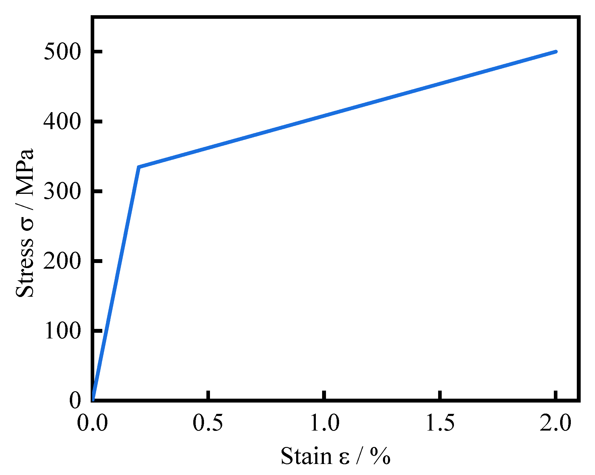
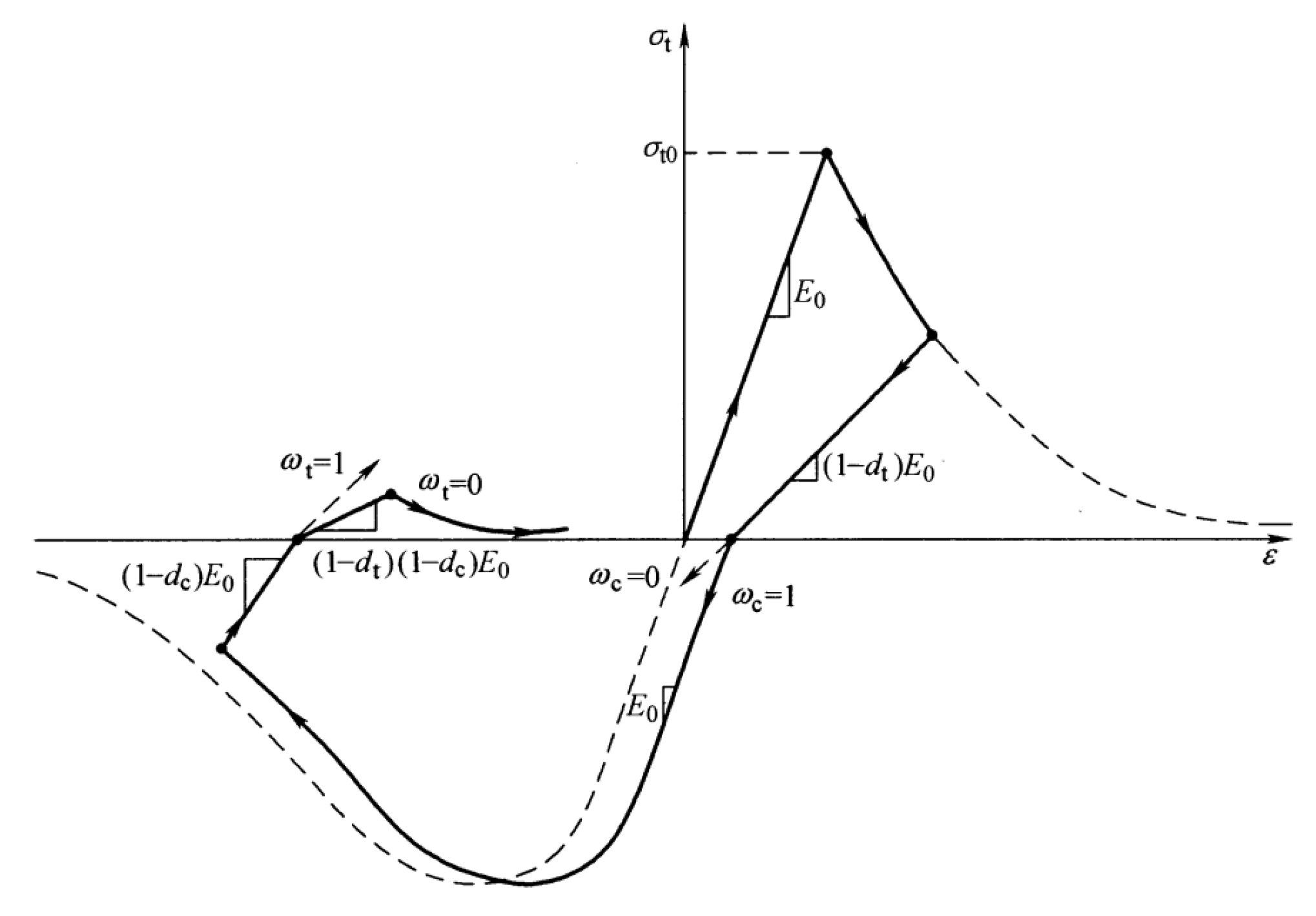
2.3. Material Constitutive Relation Selection

In this paper, the stress-strain relationship curve of the triple-fold model is used for the steel constitutive model. As shown in Figure 2. Triple-fold model can be more accurate for the analysis and description of large deformation compared with the two-fold. The constitutive relations of concrete uses Han’s core concrete model for CFST [13], and also consider the plastic damage in ABAQUS/Standard [14] and its plastic parameters use the software default values, as shown in Table 2.
The stiffness of joint degrades with increasing load, thus the tensile damage factor dt and compressive damage factor dc are used to represent the change in material modulus [14], and their stress-strain curves in tension and compression are shown in Figure 3.

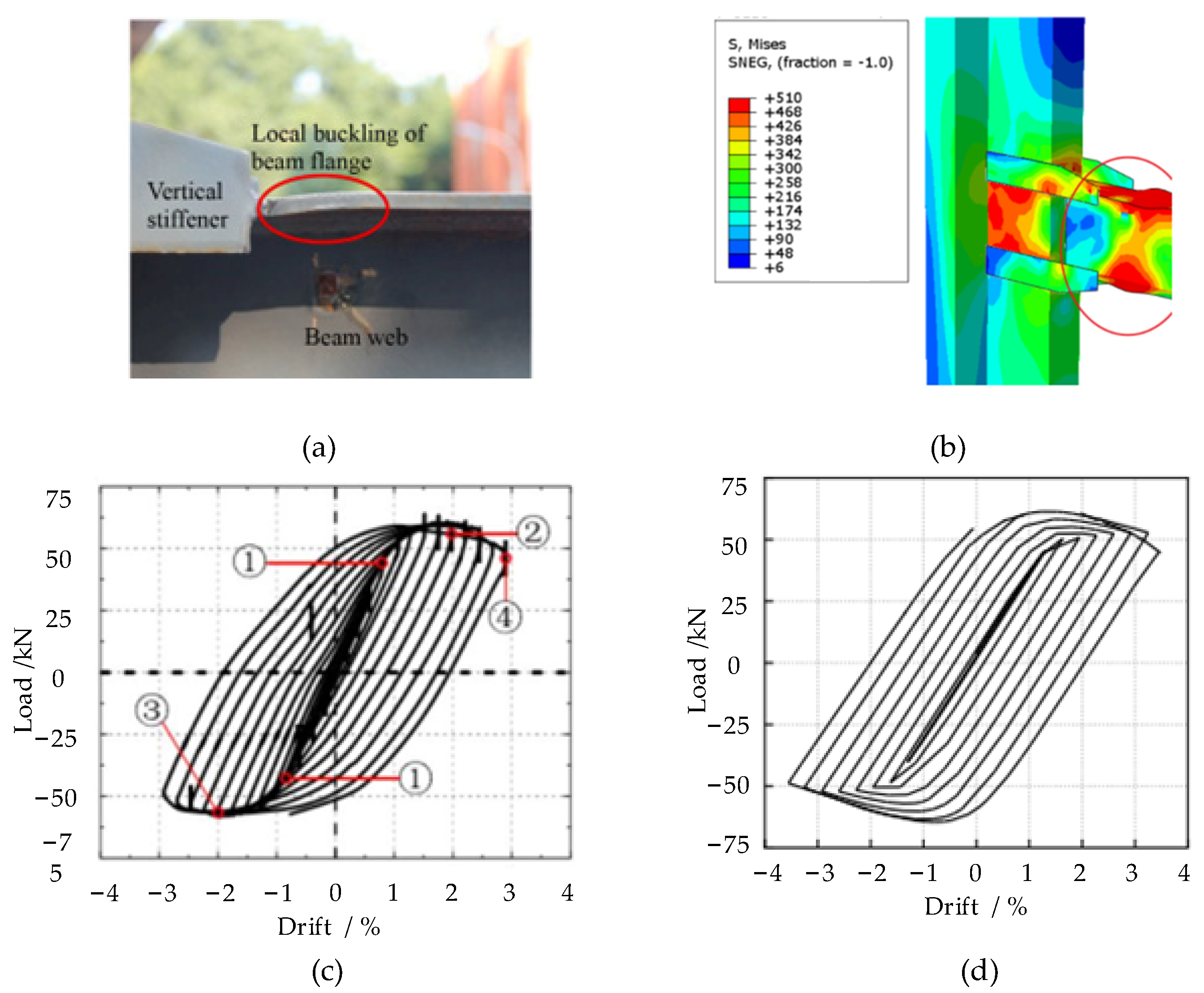
2.4. Verification of Finite Element Model

In order to verify the material intrinsic model, interaction, boundary conditions, reasonableness and accuracy of the analysis method selected for the FE model establishment, the simulation calculation and verification of the reference [15] joint specimen E-C-VN-0.3 was carried out. The comparison of deformation and hysteresis curves is shown in Figure 4. The finite element model results are in great agreement with the test, which verifies the feasibility of the FE model.

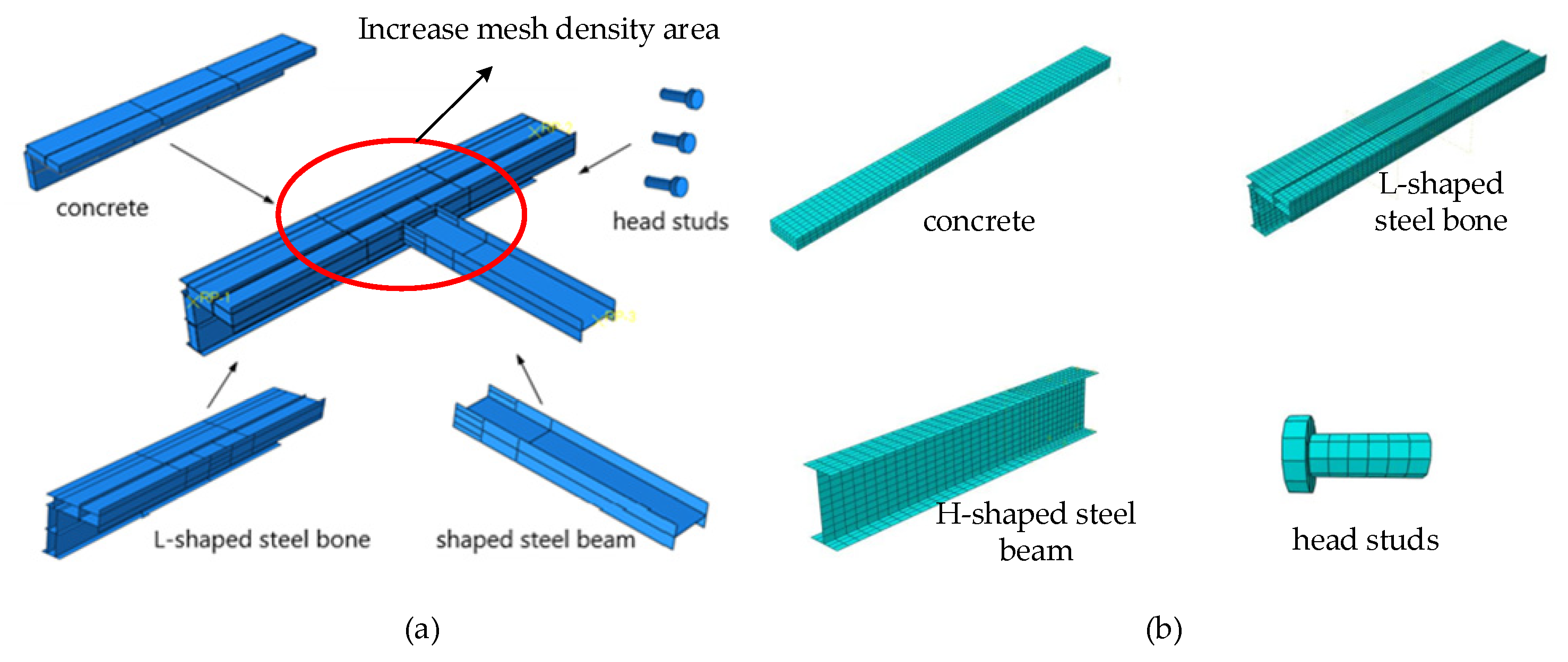
2.5. Establishment of Finite Element Model

The joint models of the five S series joints and a JD joint were established, and the material constitutive, unit type selection, boundary conditions, contact relations and other related parameters required for ABAQUS/Standard finite element analysis were set. The C3D8R solid element is used for concrete and studs. The S4R shell element is used for the steel plate members, which is characterized by its ability to withstand twisting deformation. The S4R shell unit is characterized by finite membrane strain and large rotation. By refining the local grid, the mesh size is 30 mm in the joint area and 50 mm in the others. The mesh size of head studs is 10 mm.
The beam ends, column tops, column bottoms’ concrete sections and steel sections are coupled at one point, and displacement constraints are applied at the reference point. The composition of the final joint model is shown in Figure 5. The contact action defined by the model is as follows.
(1)
Concrete and L-shaped steel-reinforced member: concrete and steel-reinforced member are surface to surface contact, with the inner surface of the steel-reinforced member with high elastic modulus selected as the main surface. The softer concrete surface as the slave surface, with the distance as the default option. The tangential property is defined as having friction with using the penalty function operation method, and the default friction coefficient is 0.6 [16]. The normal attribute is defined as hard contact, and this definition indicates that when the inner surface of the steel is separated from the outer surface of the concrete, the constraint is also removed. The contact pressure between the two surfaces is zero.
(2)
Between the steel components: L-shaped steel-reinforced member and steel beam, head studs and column flange are welded. Choose TIE to constrain two surfaces to simulate the weld and the surface of L-shaped steel-reinforced member as the main surface. Then take the welding surface of steel beam and head stud as the slave surface. Its binding area is selected using Joint region (point set method) as the slave joint, and the distance is the default option.
(3)
Concrete and joint-transmitting elements: concrete and head studs are embedded contact. The head studs are selected to be embedded in the concrete.
Figure 5. Assembly and mesh schematic diagram. (a) Assembly; (b) Mesh.
Metals 13 00601 g005

3. Calculation Results and Analysis

3.1. Calculation Results and Analysis of Monotonic Loading

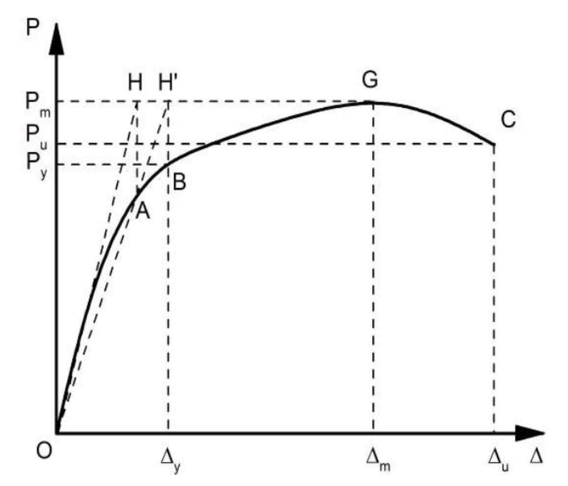
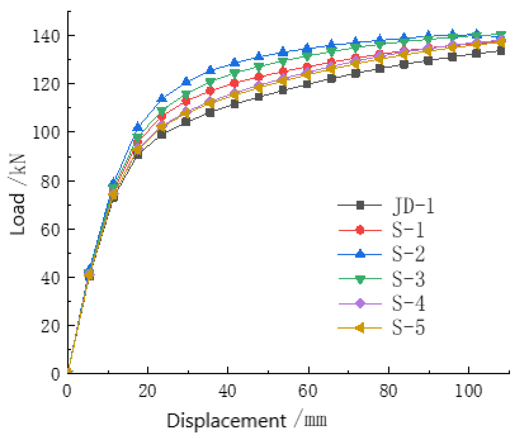
3.1.1. Load-Displacement Curve Analysis

The monotonic loading method was used to apply a vertical downward load along the Z-axis at the beam end of the five joints of the S series, while an axial compression ratio of 0.3 was used. Apply an axial compression load at the top of the column. Based on the same loading method and experiment conditions, loads are applied to the JD joints (the difference with the S series is that the beams and columns of JD joints are directly welded without any connection in between). The yield-bearing capacity, yield displacement and ultimate bearing capacity of five joints of S series under monotonic loading were obtained and compared with the JD joint model for analysis.
Regarding the determination of the yield point, since the load-displacement curve under monotonic loading has no descending section, the geometrical plotting method is taken to determine the yield point of each model. The value of the ultimate bearing capacity is taken according to the Technical Regulations for High-rise Civil Steel Structures (JGJ99-2015) [17]. Select the bearing capacity of the joint model when the allowable value of the interlayer displacement angle is 0.05 rad. The specific way of determination is shown in Figure 6.
The load-displacement curves of S series 5 joints and JD joint model under monotonic loading are compared, as shown in Figure 7. It can be seen that the yield bearing capacity, ultimate bearing capacity and yield displacement of JD joint model are 99.1 kN, 128 kN and 20 mm respectively. The specific values of yield bearing capacity, yield displacement and ultimate bearing capacity of S series 5 joint models are shown in Table 3.

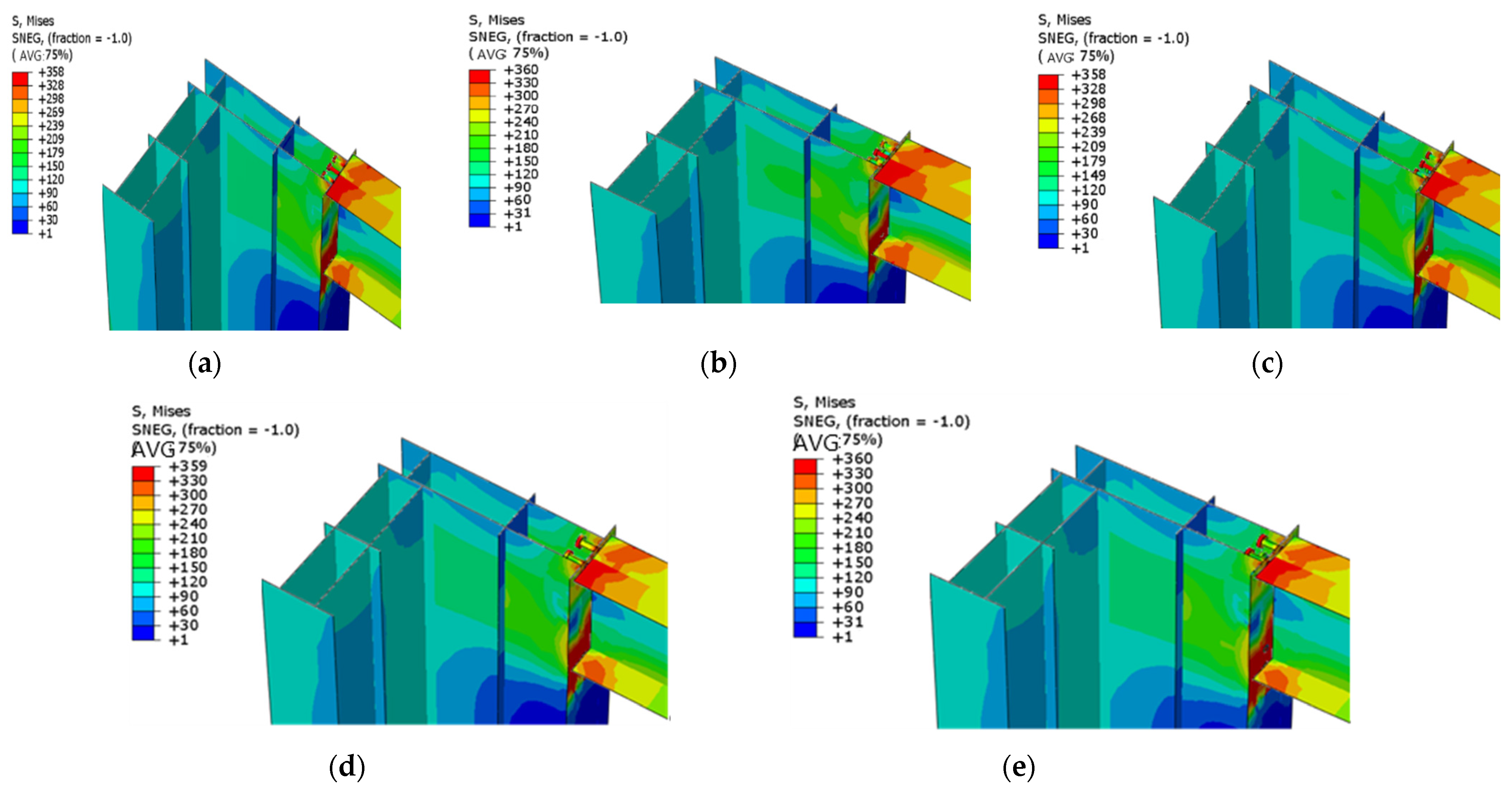
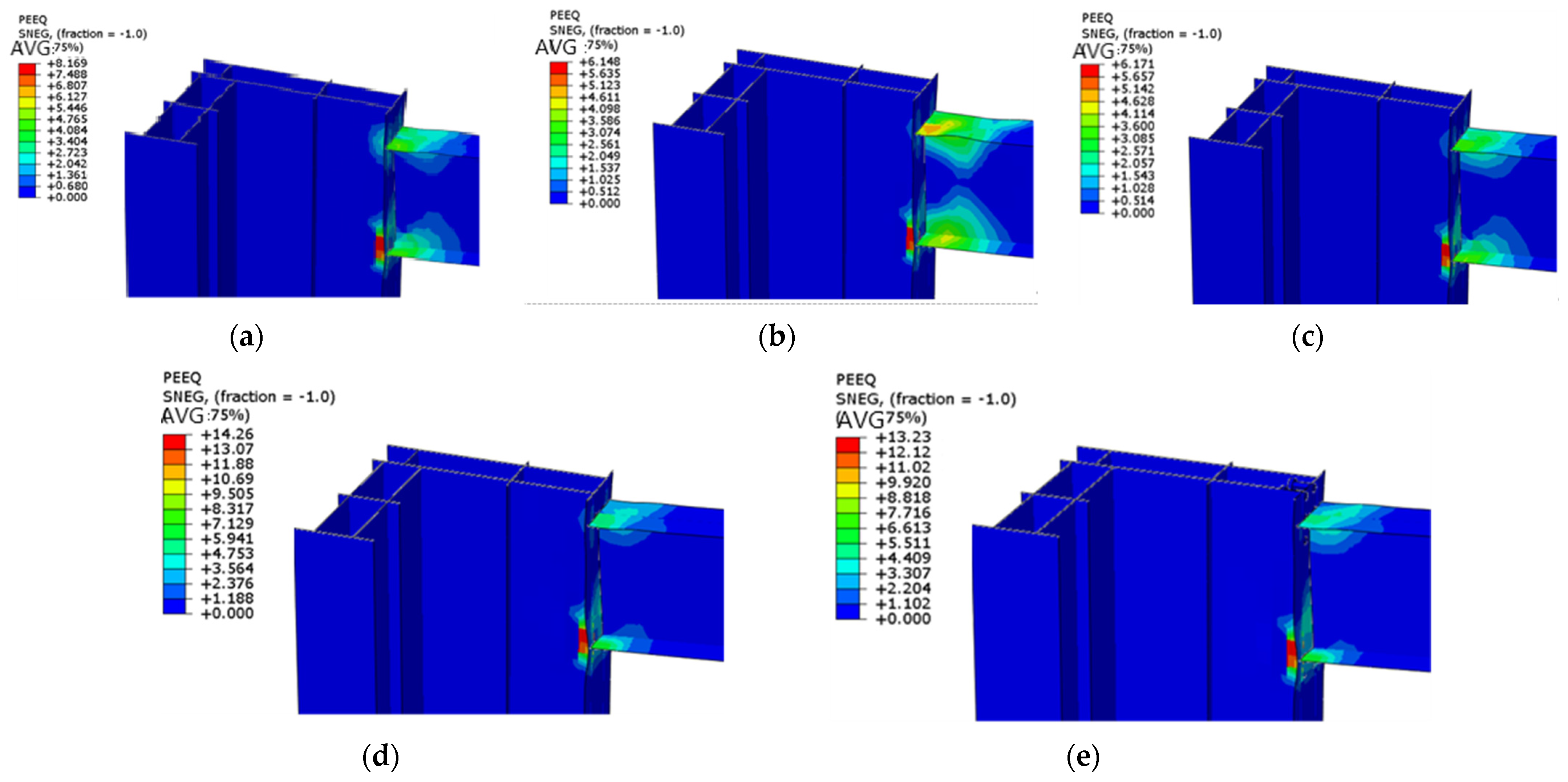
3.1.2. Analysis of Yield State and Failure Mode of Joints

The Mises stress of the five joints of the S series when they reach the yield state are obtained by using ABAQUS/Standard. Equivalent plastic strain of the S series’ five joints when the beam end displacement is loaded to 100 mm are obtained, then the final damage mode of each joint model of the S series can be determined.
When the joints yield as a whole, the Mises stress of the 5 joints at the beam-column are shown in Figure 8. It can be seen that when the 5 joints yield, the column web and column flange, the upper and lower flange of the beam end, and the part of the head studs have reached the yield stress of the material. At the same time, the beam web has not yet entered yield. The transfer of force of the S series joints is that the bending moment of the beam end is transformed into the pressure of the upper flange of the beam and the tension of the lower flange of the beam to the column flange. The column flange is transferred to the column web and the head stud, and the column head of the head stud on the beam flange transfers the pressure to the concrete of the joint domain. The column head squeezes the surrounding concrete outward, which can effectively transfer the load directly to the base material. The stress at the column head grows and finally reaches the yield strength of the material. The column head of the head studs at the lower flange of the beam converts the tensile force into pressure on the surrounding concrete, while the column head squeezes the concrete inward. With the increasing displacement effect at the end of the beam, cracks appear in the concrete of the nodal domain and gradually form a cone of destruction. Then the pressure is transferred to the column web and column flange. The vertical shear force at the end of the beam is transferred to the column flange and head studs, while the column flange and head studs are transferred to the concrete by bonding and squeezing respectively.
The equivalent plastic strain of the joints is shown in Figure 9. It can be seen that the upper and lower flange of beams and webs of S-2, S-3 joint buckle, and plastic hinge are formed at the end of the beams. The plastic hinge development to the column web. S-1, S-4, S-5 joints did not form a full-section plastic hinge at the end of the beam, and the plastic hinge range and plastic strain value generated at the end of the beam are smaller than those of S-2 and S-3. The plastic deformation of the beam-column welded corner is larger than that of the S-2 and S-3 joints. Observe the damage forms of the five joints. It is known that: there are S-2 and S-3 joints form full section plastic hinge failure in the end.

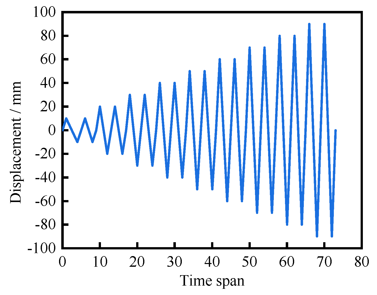
3.2. Calculation Results and Analysis of Cyclic Loading

Cyclic load is applied to S-series joints, and the ductility, energy dissipation capacity and hysteretic performance of S-series joints are analyzed by hysteretic curve, energy dissipation capacity, strength degradation and other related indexes
Cyclic load is applied to the beam end was loaded by displacement. During loading, the amplitude is increased from 10 mm to 100 mm, and the load is cycled twice per stage. The loading method is shown in Figure 10.

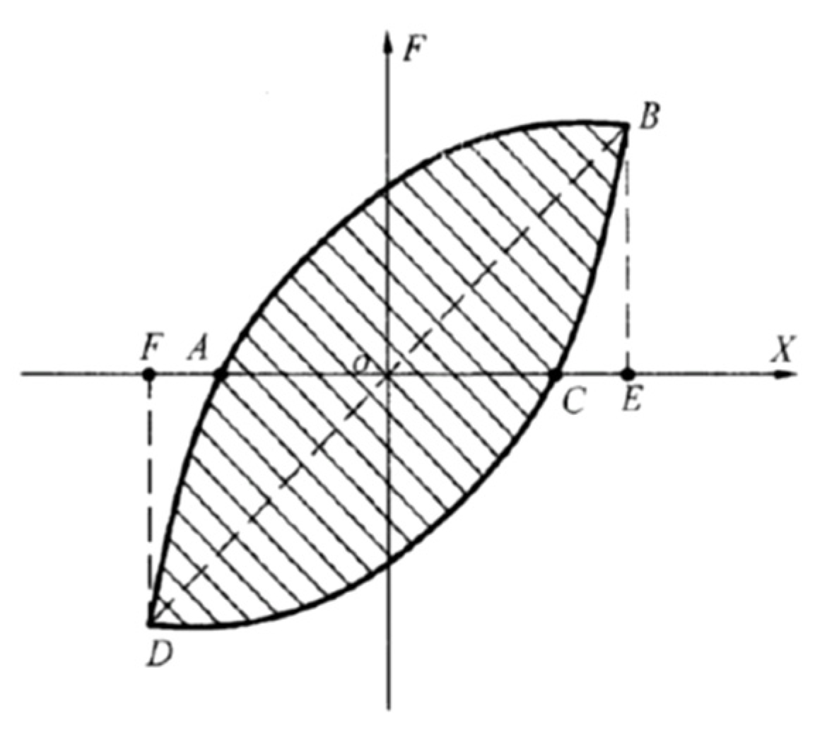
3.2.1. Hysteresis Curve Analysis

Hysteresis curve is the load-displacement relationship of the joint under cyclic loading. It can describe the deformation characteristics and energy dissipation of the joint. Hysteresis curves of all nodes of S series are shown in Figure 11. It is known that the overall hysteresis curve of S series joint model is divided into elastic phase, elasto-plastic phase, and plastic phase.
The hysteresis curves of S-1, S-2 and S-3 joints have obvious inflection points of load drop compared with S-4 and S-5 joints. The inflection points of load drop of S-2 joint occurs when the displacement of beam end is applied to about 55 mm. And the inflection points of load drop of S-1 and S-3 joints occurs when the displacement of beam end is applied to about 65 mm, which is due to the higher stress at the position of beam flange and where the cylindrical head pins are welded to the column web. S-4 and S-5 joint models have no load drop inflection point due to the larger diameter of the head studs and the larger stress of the stud at the extrusion of the column head and concrete.

3.2.2. Analysis of Energy-Consuming Capacity

The hysteresis curve under cyclic reciprocal loading can reflect the energy dissipation capacity of the joint model, and the hysteresis loop area is determined as shown in Figure 12. The energy dissipation coefficient E and equivalent viscous damping coefficient he are used to express the energy dissipation capacity of the joint model. And the larger the E and he, the better the energy dissipation capacity of the joint model. For the same joint, the values of E and he are different for different displacement loading stages, which are calculated as in Equations (3) and (4).
E = Area ( A B C + C A D ) Area ( O B E + O D F )
h e = E / 2 π
The results of energy dissipation index of S series joint model are shown in Table 4. It can be seen that the hysteresis curve of S series joint model is quite full, and the energy dissipation coefficient is between 2.2 and 2.48 when the ultimate bearing capacity is reached. The equivalent viscous damping coefficient is between 0.35 and 0.39.
The energy dissipation coefficient of S-series joints changes with displacement, as shown in Figure 13. As the displacement increases, the upper and lower flanges of the beams of S-1, S-2 and S-3 joints yield first. When the failure load is reached, the full-section plastic hinge is formed at the end of the beam to absorb energy and the energy dissipation capacity increases.
When the S-4 and S-5 joints yield, the plastic deformation of the beam flange dissipates energy, the column web is pulled outward and the energy dissipation increases. However, because when the failure load is reached, the beam end does not form a full-section plastic hinge to affect its energy dissipation capacity, its energy dissipation coefficient has been less than the other three joints of the S series under cyclic loading.

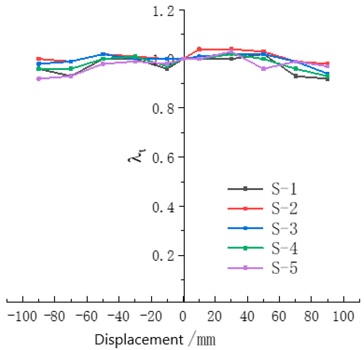
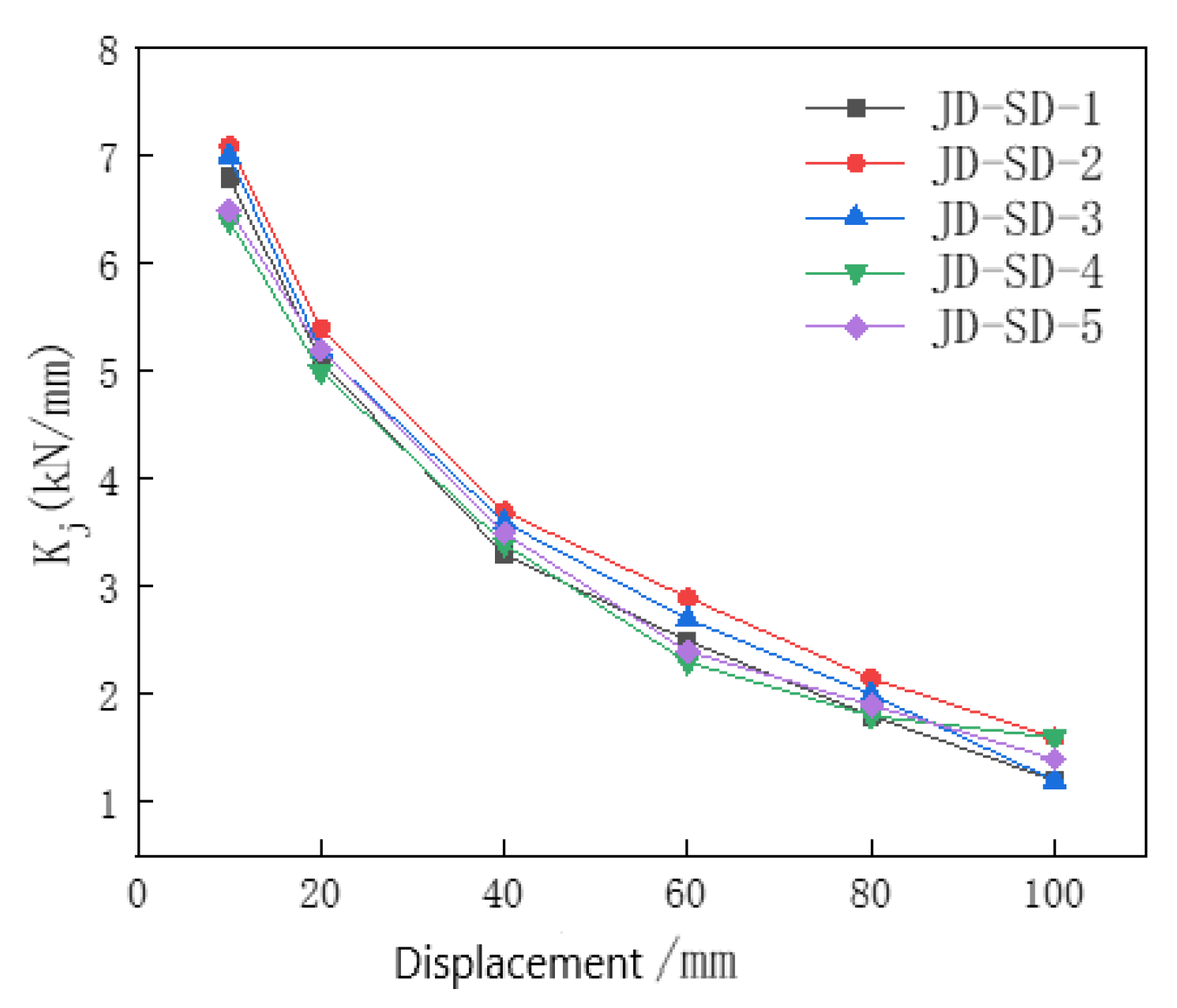
3.2.3. Strength Degradation and Stiffness Degradation Analysis

With the increase in the number of cyclic reciprocal displacement loading, the characteristic of joint bearing capacity reduction is called strength degradation. The strength degradation coefficient ‘s calculation Equation (5) is as follows.
λ i = F j i F j 1
where,
F j i ——the peak load under the jth displacement loading and the ith cyclic loading.
F j 1 ——the peak load under the jth displacement loading and the ith cyclic loading.
The strength degradation coefficients of S series joints changes with displacement, as shown in Figure 14. It can be seen that the strength of joints is between 0.95 and 1.05, without large strength degradation before joint damage, which indicates good energy dissipation capacity. After reaching the damage load, the beam ends of S-2 and S-3 joints form a full-section plastic hinge. What’s more, the beam flange and beam web buckle severely, which leads to the strength degradation gradually. The concrete in the compression zone of the joint area of the S-1, S-4 and S-5 joint models is crushed, and the concrete damage accumulation is repeatedly squeezed under cyclic loading. The beam flange and the beam web are buckled, the column flange is locally raised. The deformation of the tensile part of the column web is increased, and the strength of the joint model is gradually degraded.
Under cyclic loading, the joint model can reflect the damage degree, damage law and stiffness degradation of the model with the gradual cracking of concrete and the material entering the plastic state. These characteristics are fully reflected in the development of plastic deformation of materials. The secant stiffness degradation curve is calculated according to Equation (6).
K j i = | + F j i | + | F j i | | + X j i | + | X j i |
where,
F j i ——denotes the peak load of the hysteresis curve of the ith cycle when the j-level load is applied.
X j i ——represents the displacement value corresponding to the peak load of the ith hysteresis curve during the j-level loading.
The law of S-series stiffness degradation is shown in Figure 15. From the figure, it can be seen that the initial stiffnesses of the five joints are 6.8, 7.1, 7, 6.4 and 6.6. The initial stiffness of the joint model is increased by the three-row arrangement of the cylindrical head studs compared to one row. The stiffness of the joint model decreased faster before the displacement of 40 mm. And the stiffness of the five joints decreased by 51.5%, 47.9%, 48.6%, 46.9%, and 46.2%. The reasons are that the appearance and development of concrete cracks around the core area of the joint, near the flange part of the beam and the column head of the cylindrical head stud. The stiffness of the joint decreases slowly when the displacement is 40 mm~100 mm. At the displacement of 100 mm, the stiffness of the five joints decreases by 82.3%, 80.5%, 82.9%, 75%, and 78.5%.

4. Conclusions

In this paper, five joints of S series are designed for the section form of special-shaped double-web steel-reinforced concrete (SDSRC) columns. The mechanical properties of the joint are studied by finite element method. The stress development process, yield state, failure mode and hysteretic performance of different forms of joints under monotonic or cyclic loading are analyzed. The beam-column joint connection form suitable for the SDSRC is selected. At the same time, the internal reasons for the difference in the improvement effect of different joint forms on the mechanical properties of joints are analyzed to provide relevant suggestions for engineering applications. The main conclusions are as follows.
(1)
Comparing the damage forms of five joints of S series, only the beam ends of S-2 and S-3 joints form full-section plastic hinges. The mechanical properties of S series beam-column joints are better under monotonic loading, and all of them have greater improvement compared with JD. Especially S-2 and S-3 have obvious improvement, the yield bearing capacity is 14.8% and 10.1% higher with the ultimate bearing capacity is 13.5% and 10.9% higher.
(2)
When applying cyclic reciprocating load to the joints, S series joints all show good hysteresis performance, with full hysteresis curve. When reaching the ultimate bearing capacity, the concrete loses bearing capacity and strength and stiffness decrease due to the formation of the destruction cone between the cylindrical head and the surrounding concrete. But the joints have good ductility before and after reaching the ultimate bearing capacity.
(3)
The mechanical properties and damage modes of joints are related to the distribution of studs. The studs at the connection between the beam web and the column are obviously stressed, and the arrangement of studs here can effectively improve the force transmission at the beam-column node. Multiple rows of studs can enhance the interaction with concrete and form plastic hinges in the beam section. The single-row arrangement tends to lead to local crushing of the concrete and should be avoided.

Author Contributions

Conceptualization, Z.M.; methodology, Z.G.; software, Z.G. and Z.J.; validation, Z.G. and Y.Y.; formal analysis, Z.G.; investigation, Y.Y. and Z.G.; resources, Z.G.; data curation, Z.G.; writing—original draft preparation, Z.G. and Z.J.; writing—review and editing, Z.M. and Y.Y.; visualization, Z.G. and Y.Y.; supervision, Z.M.; project administration, Z.M.; funding acquisition, Z.M. All authors have read and agreed to the published version of the manuscript.

Funding

This research was funded by the National Natural Science Foundation of China grant number 51578064 and the Natural Science Foundation of Beijing Municipality grant number 8172031.

Data Availability Statement

All the data supporting the results were provided within the article.

Conflicts of Interest

The authors declare no conflict of interest.

References

  1. Lai, B.; Yang, L.; Xiong, M. Numerical simulation and data-driven analysis on the flexural performance of steel reinforced concrete composite members. Eng. Struct. 2021, 247, 113200. [Google Scholar] [CrossRef]
  2. Nguyen, T.; Thai, H.; Li, D.; Wang, J.; Uy, B.; Ngo, T. Behaviour and design of eccentrically loaded CFST columns with high strength materials and slender sections. J. Constr. Steel Res. 2022, 188, 107004. [Google Scholar] [CrossRef]
  3. Hassam, M.; Guo, L.; Jia, C. Concentric and eccentric compression performance of multiple-cell cruciform CFSTs. J. Constr. Steel Res. 2022, 192, 107205. [Google Scholar] [CrossRef]
  4. Zhan, X.; Qin, Z.; Li, J.; Chen, Y. Global stability of axially loaded partially encased composite column with L-shaped section. J. Constr. Steel Res. 2023, 200, 107671. [Google Scholar] [CrossRef]
  5. Chen, Z.; Mo, L.; Li, S.; Liang, Y.; Xu, D. Seismic behavior of steel reinforced concrete L-shaped columns under compression-bending-shear-torsion combined action. J. Build. Eng. 2021, 42, 102498. [Google Scholar] [CrossRef]
  6. Chen, Z.; Xu, J.; Zhou, T.; Su, J. Seismic research on column base joint of L-shaped CFST columns under cyclic loading. Structures 2022, 45, 1212–1224. [Google Scholar] [CrossRef]
  7. CECS 159-2004; Technical Specification for Structures with Concrete-Filled Rectangular Steel Tube. China Association for Engineering Construction Standardization: Beijing, China, 2004.
  8. Spavier, P.T.D.S.; Debs, A.L.H.C. Experimental analysis of beam-to-column connection with partially encased concrete column with varying inertia axis. J. Constr. Steel Res. 2022, 194, 107325. [Google Scholar] [CrossRef]
  9. Zhou, W.; Li, B.; Zhao, G.; Gao, C. Experimental study of seismic performance of PEC column-steel beam 3D frame with endplate connection. J. Constr. Steel Res. 2023, 202, 107765. [Google Scholar] [CrossRef]
  10. Guo, L.; Wang, J.; Wang, W.; Hu, Z. Experimental and numerical investigations of bolted assembled joints to concrete encased CFST columns with different connection details. J. Constr. Steel Res. 2023, 201, 107739. [Google Scholar] [CrossRef]
  11. Gautham, A.; Sahoo, D.R. Performance of SRC column-RC beam joints under combined axial and cyclic lateral loadings. Eng. Struct. 2022, 260, 114218. [Google Scholar] [CrossRef]
  12. GB50011-2010; Code for Seismic Design of Buildings. China Architecture & Building Press: Beijing, China, 2016.
  13. Han, L.; Yao, G.; Tao, Z. Performance of concrete-filled thin-walled steel tubes under pure torsion. Thin-Walled Struct. 2007, 45, 24–36. [Google Scholar] [CrossRef]
  14. Hibbitt, K.S. ABAQUS/standard User’s Manual, Version 6.5.; Dassault Systèmes Corp.: Waltham, MA, USA, 2005. [Google Scholar]
  15. Cheng, Y.; Yang, Y.; Li, B.; Liu, J.; Chen, Y.F. Mechanical behavior of T-shaped CFST column to steel beam joint. J. Constr. Steel Res. 2021, 187, 106774. [Google Scholar] [CrossRef]
  16. Chen, Z.; Mohammed, A.; Du, Y.; Mashrah, W.A.H.; Zhao, B.; Huang, J. Experimental and numerical study on seismic performance of square and l-shaped Concrete-filled steel tubes column Frame-Buckling steel plate shear walls. Eng. Struct. 2023, 274, 115155. [Google Scholar] [CrossRef]
  17. JGJ 99-2015; Technical Specification for Steel Structure of Tall Buildings. China Architecture & Building Press: Beijing, China, 2015.
Figure 1. Schematic diagram of beam-column joints. (a) JD joint for comparison (unit: mm); (b) S series joint (unit: mm); (c) Schematic diagram of stud position.
Metals 13 00601 g001
Figure 2. Stress-strain relationship of steel.
Metals 13 00601 g002
Figure 3. Constitutive relation curve of uniaxial cyclic tension-compression of concrete [14].
Metals 13 00601 g003
Figure 4. Test results and finite element model validation. (a) Deformation of test; (b) Deformation of FE (unit: MPa); (c) Hysteresis curves from test; (d) Hysteresis curves from FE.
Metals 13 00601 g004
Figure 6. Geometrical plotting method.
Metals 13 00601 g006
Figure 7. Load-displacement curve under monotonic loading.
Metals 13 00601 g007
Figure 8. Mises stress cloud (unit: MPa). (a) S-1; (b) S-2; (c) S-3; (d) S-4; (e) S-5.
Metals 13 00601 g008
Figure 9. Equivalent plastic strain cloud diagram (unit: %). (a) S-1; (b) S-2; (c) S-3; (d) S-4; (e) S-5.
Metals 13 00601 g009
Figure 10. Reciprocating cyclic loading system.
Metals 13 00601 g010
Figure 11. Joint hysteresis curve. (a) S-1; (b) S-2; (c) S-3; (d) S-4; (e) S-5.
Metals 13 00601 g011
Figure 12. Determination of hysteresis loop area.
Metals 13 00601 g012
Figure 13. Energy dissipation coefficient of S Series joints with displacement.
Metals 13 00601 g013
Figure 14. The strength degradation coefficient of S series joints varying with displacement.
Metals 13 00601 g014
Figure 15. Stiffness degradation coefficient of S series joints varying with displacement.
Metals 13 00601 g015
Table 1. S series related parameters of each joint.
NumberCylindrical Head Stud SizeStuds Distribution and Spacing
d 0 d k k L
S-110187401 row
S-210187403 row; spacing 2 d 0
S-310187403 row; spacing 4 d 0
S-416298501 row
S-516298503 row; spacing 2 d 0
Table 2. C40 Concrete material parameters.
Poisson Ratio   μ Dilation Angle   ψ Eccentricity Ratio   ε fb0/fc0 Specific Value   K Viscosity Parameter
0.230°0.11.160.66670.005
Table 3. S series and JD joint simulation results.
ModelYield Bearing Capacity/kNYield Displacement/mmUltimate Bearing Capacity/kN
JD99.120128
S-1106.724.5133.7
S-2113.823139
S-310924137.6
S-410226133.1
S-5102.726132
Table 4. S series joint energy consumption index.
NumberEnergy Dissipation Coefficient EEquivalent Viscous Damping Coefficient h e
S-12.310.35
S-22.490.39
S-32.460.39
S-42.440.37
S-52.210.36
Disclaimer/Publisher’s Note: The statements, opinions and data contained in all publications are solely those of the individual author(s) and contributor(s) and not of MDPI and/or the editor(s). MDPI and/or the editor(s) disclaim responsibility for any injury to people or property resulting from any ideas, methods, instructions or products referred to in the content.

