Article

Q&P Response of a Medium Carbon Low Alloy Steel

1
Laboratory of Advanced Steels for Agricultural Machinery, Russian State Agrarian University–Moscow Timiryazev Agricultural Academy, 127550 Moscow, Russia
2
Laboratory of Mechanical Properties of Nanostructured Materials and Superalloys, Belgorod State National Research University, 308015 Belgorod, Russia
3
National Research Center “Kurchatov Institute”–Central Research Institute of Structural Materials “Prometey”, 191015 St. Petersburg, Russia
*
Author to whom correspondence should be addressed.
Metals 2023, 13(4), 689; https://doi.org/10.3390/met13040689
Submission received: 27 February 2023 / Revised: 28 March 2023 / Accepted: 29 March 2023 / Published: 31 March 2023

Abstract

:
An Fe-0.44%C-1.8%Si-1.3%Mn-0.82%Cr-0.28%Mo steel was subjected to quenching followed by low-temperature tempering (Q&T) and quenching and partitioning (Q&P) processing after full austenitization. The Q&P treatment led to an increase in the volume fraction of retained austenite (RA) by factors ranging from 30 to 40 depending on the quenching temperature, Tq, and an additional precipitation of transition η-carbides in the martensitic matrix. The Q&P processing provided a decrease in the yield stress (YS) from 1730 to 1350 MPa and an increase in the ductility by a factor of 3; the product of strength and elongation (PSE) increased from 13.7 to 32 GPa·%. The novelty of the work lies in establishing the origin of the good ductility and high YS of Q&P steel. Blocky-type RA plays a vital role in the effect of Q&P processing on mechanical properties. The main feature of RA is a very high dislocation density proving the strength of ~1000 MPa of this structural component. The strength of RA controls the YS of the steel if its volume fraction is ≥25%. Ductility is provided by the almost full transformation of RA into strain-induced martensite under tension. The localization of plastic deformation in the form of deformation bands is associated with the γ→α′ transformation. Medium carbon Q&P steel with a high volume fraction of RA meets the requirements for advanced high-strength steel (AHSS) belonging to the third generation of AHSS due to the combination of the YS > 1050 MPa with the PSE > 30 GPa·%.

1. Introduction

The strength and ductility are the key properties of advanced high-strength steels (AHSS) [1]. Materials may be strong or ductile, but the combination of high strength with good ductility is rare. A widely adopted criterion describing the combination of strength and ductility having opposing characteristics is the product of strength and elongation (PSE), σB·δ (MPa·%) [2,3,4,5,6,7]. The first generation of AHSS exhibits elongation-to-failure ≥30% and σB·δ ~1.5 ÷ 2 × 10⁴ (MPa·%), corresponding to relatively lower ultimate tensile strength (UTS) and yield stress (YS). High-Mn steels belonging to the second generation of AHSS [1,7] exhibit σB·δ ≥ 3 × 10⁴ (MPa·%) due to δ ≥ 30% and UTS ≥ 1100 MPa, while the YS of these materials ranges from 230 to 350 MPa that is even smaller than YS of low-alloy steels belonging to the first generation of AHSS [1,7,8]. The main requirement for the third generation of AHSS is the combination of YS ≥ 1000 MPa with the PSE ranging from 2 × 10⁴ to 4 × 10⁴ MPa·% [1]. This attractive relationship between YS, UTS, and ductility, achieved through the development of Q&P (quenching and partitioning) processing, is the result of the complex behavior of the different constituent phases present in these steels [1,2,3,4,5,6,9,10,11].
The microstructural design of Q&P steels consists of the combination of carbon-depleted martensite with carbon-enriched retained austenite (RA) [1,9,10,12]. Q&P processing is a complex heat treatment consisting of at least four steps [1,9,10,12,13,14]. The first step involves full austenitization followed by rapid cooling in a salt bath to a quenching temperature, Tq, lying between the martensite-start (Ms) and martensite- finish (Mf) temperatures (Figure 1) [1,2,3,4,5,6,9,10,12,13,14]. The second step is quenching in a heated salt bath, which produces primary martensite and a considerable amount of RA. The carbon partitioning from martensite to austenite to enrich RA with carbon occurs during isothermal annealing at a temperature, Tp, that is usually above the Tq and Ms temperatures. This third step of Q&P processing is termed as “partitioning” [1,9,10,11]. The final fourth step is air cooling or water quenching from Tp to ambient temperature that leads to the partial transformation of RA into secondary martensite distinguished by morphology, higher dislocation density, and carbon content from primary martensite [12]. In addition, transition carbides are rarely observed in secondary martensite compared to primary martensite [12]. Typically, the temperature of partitioning, Tp, is higher than Ms, but there are Q&P routes in which Tp lies below Ms or even Ms = Tp [1,2,3,4,10,14].
The combination of high YS > 1000 MPa and PSE ≤ 2 × 10⁴ MPa·% can normally be achieved in low alloy Q&P steels with a carbon content ranging from 0.2 to 0.3% [1,9,15]. In contrast, a PSE ≥ 3 × 10⁴ MPa·% and YS > 1000 MPa were reported for Q&P steels with a carbon content ranging from 0.4 to 0.56% [2,3,4,5,6]. These mechanical properties are associated with a volume fraction of RA ranging from 12 to 30% and a carbon content of ~1.3 wt.% in RA [5]. A major portion of RA belongs to the blocky-type [2,3,4,5,6]. A relatively high elongation is attributed to the transformation-induced plasticity (TRIP) effect associated with the almost complete transformation of RA into → strain-induced martensite under tension [2,9,10]. These data support the work of Xiong et al. [16], which reported on the easy transformation of blocky RA into martensite at low strains. Recently, X.X. Dong et al. [6] showed that blocky RA with a high volume fraction of 26 wt.% and a carbon content of 1.14 wt.% is responsible for the high PSE value in a Q&P steel with 0.5 wt.% C. These data for Q&P steels are in contrast with the effect of carbon content and the morphology of RA on the mechanical properties of TRIP steels with a bainitic matrix [17,18]. In Q&P steels with a carbon content of ~0.2 wt.%, the volume fraction of RA is ≤10% [6,19,20]. Film-like RA is dominant and the blocky type of RA is rarely observed in these steels [6,20,21]. The volume fraction of RA decreases under tension insignificantly [6], confirming the high stability of film-like RA under plastic deformation [21]. These Q&P steels are characterized by a PSE value ranging from 2 × 10⁴ to 2.72 × 10⁴ MPa·% and a YS ranging from 1050 to 1238 MPa [6,20,21] and, therefore, Q&P steels with a low carbon content may meet the requirements for AHSS belonging to the third generation [1]. It is worth noting that the carbon content in RA is nearly the same as in low carbon and medium carbon Q&P steels [2,3,4,5,6,20,21].
Thus, there exist two different types of low alloy Q&P steels exhibiting a PSE ≥ 2 × 10⁴ MPa·% and a YS > 1000 MPa. The first type is medium carbon steels with a dominance of blocky RA. The second type is low carbon steels with a dominance of film-like RA. It is apparent that the mechanisms responsible for the mechanical behavior of these two types of Q&P steels are different. The origin and nature of the tensile behavior of Q&P steels with a multiphase structure is a difficult task as it requires information on the strength and plasticity of the constituent phases and the mechanism of the interaction between the constituents under tension [12]. At present, the mechanical behavior of Q&P steels with medium carbon levels is clearer than that of low carbon Q&P steels. Obviously, the ductility of medium carbon Q&P steels is attributed to the TRIP effect. However, there is no unambiguous interpretation of the origin and nature of high YS of advanced high-strength steels. The multi-phase mixture rule is commonly used to describe the YS of Q&P steels with a martensitic matrix and RA [1,11,12,22,23]:
YS = i = 1 N ( σ 0.2 i f i )
where σ 0.2 i   and fi are the YS and volume fraction of primary martensite, secondary martensite, and RA, respectively. However, RA was considered as a soft phase with a low dislocation density [12,22], and the dislocation strengthening of RA was discarded [23], despite the very high dislocation density observed experimentally in this phase [21]. Thus, the question of the significance of retained austenite in achieving high YS remains open.
The aim of the present study is to report on the mechanical behavior of a 0.44% C steel processed with Q&P treatment compared to quenched and tempered (Q&T) steel. The second aim is to consider the origin of the good ductility and high YS of this material. Specific attention is paid to the examination of the role of RA in tension behavior.

2. Materials and Methods

An Fe-0.44%C-1.81%Si-1.33%Mn-0.82%Cr-0.28%Mo (in mass pct.) steel was produced by means of air induction melting followed by electro-slag remelting. Next, the steel was subjected to solution treatment at 1150 °C for 4 h followed by forging at temperatures from 1150 to 950 °C into a billet with dimensions of 60 × 150 × 450 mm3 with subsequent air cooling. Samples with 3 mm thickness were machined from the billet and subjected to austenitization at 900 °C for 5 min followed by quenching in a salt bath heated to different temperatures, Tq, ranging from 140 to 300 °C for 15 s and subsequent partitioning at a temperature, Tp, of 400 °C for 60 s in a salt bath (Q&P processing). In addition, the samples after austenitization were water quenched and tempered at 200 and 280 °C for 1 h (Q&T treatment). The Q&T and Q&P processes are shown in Figure 1.
Hardness was measured using an Wolpert Wilson 600 MRD (Illinois ToolWorks Inc., Norwood, MA, USA) tester in accordance with the ASTM E18 standard at room temperature. The flat specimens with a gauge length of 35 mm and a cross-section of 7 × 3 mm2 were cut from the Q&T and Q&P samples and then tensioned using an Instron 5882 testing machine (Illinois ToolWorks Inc., Norwood, MA, USA) at room temperature and an initial loading rate of 1 mm/min in accordance with the ASTM E08M-04 standard. The Portevin–Le Chatelier (PLC) bands were observed using the digital image correlation (DIC) method described in [24] on Q&P samples only. This method made it possible to record the change in the distribution of local strain fields on the surface of the sample during testing by correlating successive images of the speckle pattern. The calculations were performed using the Vic-2D correlation program (Correlated Solutions, Inc., Irmo, SC, USA). Local strain rate values were determined by numerically differentiating strain data with respect to time.
Structural characterization was carried out using a Quanta 600 FEG scanning electron microscope (SEM) (FEI Corporation, Hillsboro, OR, USA) equipped with an electron backscatter diffraction (EBSD) pattern analyzer incorporating an orientation imaging microscopy (OIM) system and a JEOL JEM-2100 (JEOL Ltd., Tokyo, Japan) transmission electron microscope (TEM). The study of the structure was carried out in the central part (depth) of the sample. Foils for TEM studies were prepared by means of double-jet electro-polishing using a solution of 10% perchloric acid in glacial acetic acid under a voltage of 21.0 V at an ambient temperature. Surfaces of the specimens for SEM observation were mechanically polished and then electropolished using the same electrolyte. These specimens were examined using the EBSD technique. The OIM images were subjected to a clean-up procedure, setting the minimal confidence index to 0.1. The low- (LAB) and high-angle (HAB) boundaries were defined with misorientations of 2° ≤ θ < 15° and ≥15°, respectively, and depicted in the OIM images using white and black lines, respectively. The density of lattice dislocation on TEM micrographs, ρTEM, was estimated by counting individual dislocations within martensite and RA per unit area [25]. In addition, densities of lattice dislocations were calculated from misorientation maps obtained by means of the EBSD technique using Kernel misorientation [26]:
ρ KAM = 8 θ KAM 3 3 b · h
where b is the Burgers vector, and the distance h corresponds to the step size of the scanning. The ρ K A M value characterizes the elastic bending of the crystal lattice and, therefore, the internal elastic stress-field originated from lattice dislocations since it is assumed that all dislocations have the same Burgers vector. The data processing and application of parent austenite grains reconstruction algorithms were performed in the open-source crystallographic toolbox MTEX 5.8 with the software suite ORTools [27]. A threshold of 3° was used to separate the grains. A graph clustering method was applied to reconstruct prior austenite grains (PAG) on misorientation maps [27,28]. The different packets (variant selection) were determined as the closest {111} plane in austenite to a {011} plane in martensite [27,28] using the technique of parent grain reconstruction described by Niessen et al. [27].
The volume fraction of RA was determined by means of magnetic saturation measurements using a Fischer Feritscope FMP30 (Helmut Fischer Gmbh, Sindelfingen, Germany) and X-ray analysis using a Rigaku Ultima IV diffractometer (Rigaku Co., Tokyo, Japan) with a step size of 0.02 deg, 40 kV and 40 mA and a 2θ Bragg angle range from 30 to 135°. X’pert High Score Plus software was used to calculate the volume fraction of RA according to the peaks intensities for an fcc lattice: (200)γ, (220)γ, (311)γ and bcc lattice: (200)α′, (211)α′, (220)α′ [29]. The volume fraction of RA, Vγ, was calculated from the integrated intensity of the austenite and martensite peaks in the manner explained in work [30] in detail. The austenite lattice parameter aγ was obtained by means of the Nelson–Riley extrapolation method [29]. The average concentration of carbon in RA was calculated using the well-known equation proposed by Dyson and Holmes [30,31]:
α γ ( A ) = 3.578 + 0.33 C RA + 0.00095 Mn RA + 0.0031 Mo RA
where CRA, MnRA, and MoRA are the concentration of carbon, manganese, and molybdenum in RA in wt.%, respectively. The CRA value was calculated from the lattice parameter obtained experimentally, while MnRA and MoRA values were taken as the Mn and Mo content in the steel, taking into account the fact that no partitioning of substitutional atoms occurs during the Q&P process [12].
The Ac3 and Ac1 critical temperatures were calculated by means of the Thermo-Calc software (Ver. 5, Thermo-Calc Software, Stockholm, Sweden) using the TCFE7 database. The dilatometry curve obtained during cooling from 900 °C to room temperature at a cooling rate of 100 °C/s using a DIL 805 dilatometer (TA Instruments Inc., New Castle, DE, USA) was used to determine the MS and MF temperatures on cylindrical samples with a 10 mm length and a 3 mm diameter.

3. Results

3.1. Critical Temperatures and Q&T/Q&P Route

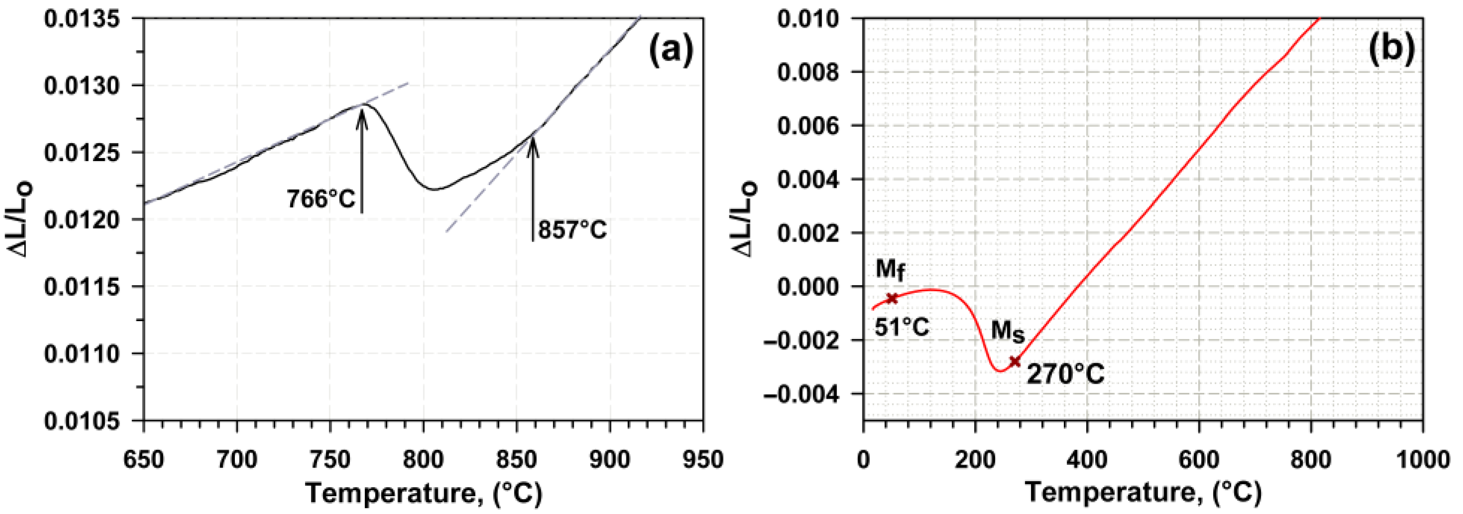
Before the development of the Q&P route, the Ac1, Ac3, MS, and MF critical points were defined, and these are summarized in Table 1. It is seen that the Ac1 and Ac3 temperatures determined by the dilatometry curve (Figure 2a) are 31 and 59 K higher than those calculated by means of Thermo-Calc software. According to the results of dilatometry analysis, it was revealed that the temperature Ac1 for the studied steel is about 760 °C and the Ac3 temperature is 857 °C. Therefore, the optimal austenitization temperature to obtain fully austenitic structure and to hinder the growth of prior austenite grains for new Fe-0.44C steel is T = 900 °C. Figure 2b shows the dilatometry curve obtained during cooling from 900 °C to room temperature. The martensite-start (MS) and martensite-finish (MF) temperatures were determined as 270 and 51 °C, respectively, with a high accuracy. Therefore, water quenching provides a low fraction of RA, and quenching in a salt bath with a temperature ranging from ~100 to 250 °C leads to the formation of a multiphase structure consisting of primary martensite and RA. At T > 270 °C, no martensitic transformation may occur under isothermal conditions.
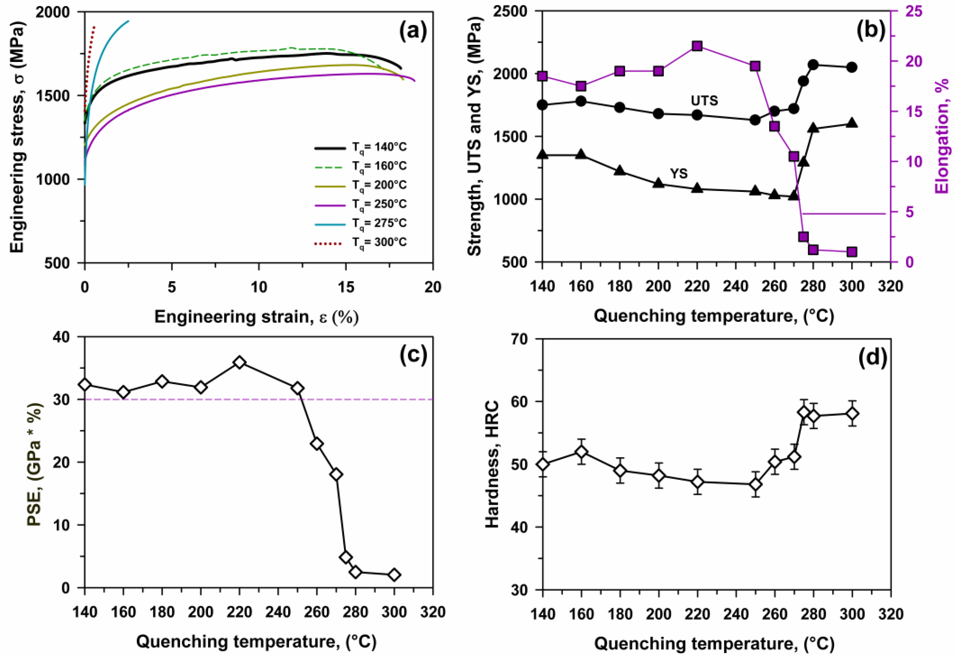
Four quenching temperatures, Tq, of 140, 160, 200, and 250 °C, were chosen for Q&P processing, lying between the MS and MF temperatures, in order to produce structures with different volume fractions of RA. Quenching at a Tq of 300 °C was also carried out for comparison. A partitioning temperature of 400 °C above MS was used. Therefore, the multiphase structure that evolved after Q&P processing may consist of primary martensite, RA, and secondary martensite. Q&T treatment with tempering temperatures of 200 and 280 °C was also performed to compare structures and constitutive phases that evolved after Q&P and Q&T processing.

3.2. Microstructure

3.2.1. Q&T

The typical microstructure after water quenching is presented in Figure 3a–c. Relatively coarse PAGs with an average size of ~28 μm could be distinguished (Figure 3a,b). At the same time, the average distance between HABs of 1.3 μm is small. This is attributed to the fact that packets which are aggregations of the blocks with the same {111}γ plane [31] and strongly distinguished by dimension and shape [32] evolve within a PAG (Figure 3c). First-order packets (indicated as B and C in Figure 3c) with dimensions ≥ 10 μm and an irregular shape contain a number of blocks (>3) and are located at the boundaries of PAGs. Second-order packets with an elongated shape and an average longitudinal dimension of ~10 μm and an average transverse direction of ~3 μm (D in Figure 3c) are located on the boundaries of first-order packets or PAGs. Third-order packets consisting of one block usually appear within the matrix of first-order packets (Figure 3b,c). The other distinct feature of the lath martensite structure evolving in the present steel is a high dislocation density of ρ K A M = 5.4 × 10¹⁴ m−2. The volume fraction of RA is negligible (~0.7).
Tempering results in insignificant changes in the microstructure (not shown here). The average distance between HABs decreases down to 0.9 and 0.7 μm after tempering at temperatures of 200 and 280 °C, respectively. Precipitation of η-Fe2C transition carbides with a plate-like shape within laths takes place. These carbides have a longitudinal dimension of ~40 nm and a transverse dimension of ~14 μm after tempering at 280 °C (Figure 3d).

3.2.2. Q&P

The multiphase structure that evolved after Q&P processing (Figure 4, Figure 5, Figure 6 and Figure 7) differs from the microstructure that evolved after Q&T treatment. SEM observations (Figure 4a–c) revealed two structural components. First, there is primary martensite with dense transition carbides located parallel to habit planes within the martensite blocks [33,34]. Carbides of this type were not observed after water quenching. However, η-Fe2C transition carbides precipitated under Q&T treatment with tempering at T ≥ 200 °C, and therefore, these carbides precipitate in the matrix of primary martensite at Tq and/or Tp due to auto-tempering [33,35,36] (Figure 7). The density of η-Fe2C transition carbides is significantly higher than that after Q&T and the precipitation of these carbides along three mutually perpendicular habit planes (Figure 7c) produces a 3D array of these particles in the primary martensite plates. It is worth noting that the black matrix of primary martensite is heavily etched and looks like smooth and dark ferrite after quenching from intercritical temperature, which is indicative of carbon-depleted constituents [20,34,35,36,37]. Primary martensite exhibits plate-like shape with a high aspect ratio (AR). The volume fraction of primary martensite decreases with increasing Tq.
The second constituent is islands of secondary martensite/RA with an irregular shape (Figure 4a–c) [20,33,34,35,36,37]. These islands are gray regions of a featureless surface [20,37] and are distinctly distinguished from primary martensite by less etching and color [33,34,35]. TEM observations (Figure 7) revealed that the density of free lattice dislocations ρTEM~2 × 10¹⁵ m−2 in RA and secondary martensite is essentially the same (Table 2). It is worth noting that the very high dislocation density observed in RA by TEM and EBSD studies is in contrast with the earlier presumption [12] and could be attributed to intense plastic straining of this phase during γ→α′ transformation. In SEM micrographs (Figure 4), the secondary martensite could not be distinguished from RA by etching, which is indicative of the same carbon content in these two structural components. The secondary martensite/RA islands, characterized by high AR, are located between the plates of primary martensite. The volume fraction of this structural component increases with increasing Tq.
Isothermal holding at Tq = 300 °C resulted in the formation of martensite with nearly the same carbon content and a small fraction of lower bainite, which is typical for partitioning at a temperature above MS [38] (Figure 4d). Transition η-Fe2C carbides could be found in some blocks (Figure 4d).
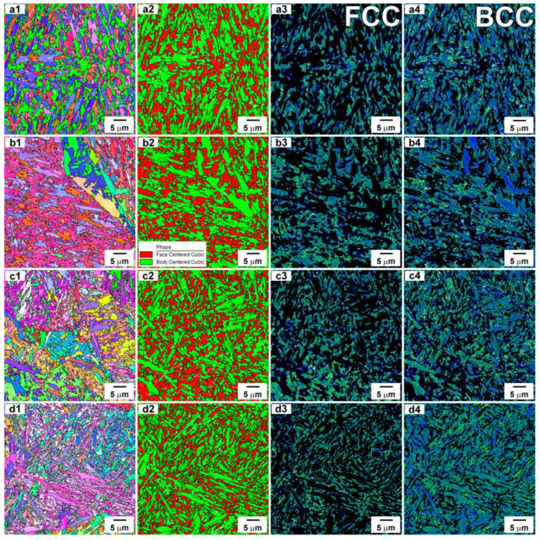
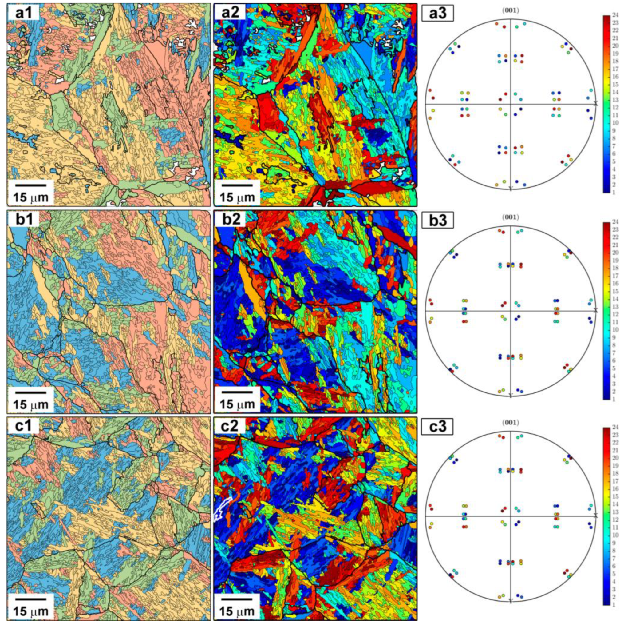
EBSD and TEM studies (Figure 5, Figure 6 and Figure 7) revealed that only PAGs and thin laths are distinctly distinguished in the lath martensite structure [32,39]. Packets could be occasionally found in primary martensite at Tq ≤ 160 °C (Figure 6) if the volume fraction of this structural component is high. The average size of PAGs is ~35 μm and the thickness of thin laths is ~300 nm (Figure 5 and Figure 7a,b). These parameters are nearly independent of Tq. The average distance between HABs decreases from 0.82 to 0.6 μm with increasing Tq from 140 to 250 °C, which is attributed to the increased portion of secondary martensite/RA constituents. Boundaries between the secondary constituent and primary martensite are HABs, and these boundaries replace packet and block boundaries in the hierarchy of lath martensite structure [39]. It is worth noting that well-defined blocks are observed in primary martensite. The average thickness of blocks is ~2 μm, and these blocks could be distinguished in the coarse plates of primary martensite. There is no distinct difference between the lath thickness in primary and secondary martensite, while the lath length in primary martensite is significantly larger. The internal distortion is predominantly localized in secondary martensite, whereas the plates of primary martensite are nearly strain-free (Figure 5 column 4). At low Tq, the internal elastic strains are the lowest in the coarse blocks of primary martensite. As a result, increasing Tq leads to increased internal distortions (Table 2).
Quenching temperature, Tq, affects the parameters of RA (Figure 5 column 2, where RA is shown in red, and Figure 8). The RA grains exhibit an irregular blocky shape and are distributed in the martensitic matrix almost uniformly. No definite correlation between Tq and the dimension of RA blocks (Table 2)/carbon content in RA (Table 3) was found, while the volume fraction of RA increases with increasing Tq up to MS (Figure 8).
The Fe-0.44C steel is characterized by the irregular distribution of RA over the cross section of the sample (Figure 9). In addition, the size of RA blocks also varies with depth; therefore, all dimensions in Table 2 are based on the dimensioning in Figure 5. It is important to note that the investigated steel is characterized by good hardenability.
Therefore, such local methods as EBSD and SEM do not allow one to reliably determine the volume fraction of RA. So, the volume fraction of RA was determined using two methods: the X-ray technique and the magnetic induction method, which demonstrated a good correlation (Figure 8a). The volume fraction of RA increases from 16 to 25% with increasing Tq from 140 to 250 °C. The following increase in the quenching temperature from 250 to 300 °C leads to a drop in the volume fraction of RA to 5% since no primary martensite may evolve above MS. Isothermal holding at 300 °C leads to the formation of low bainite along the boundaries of PAGs and the precipitation of transition carbides in bainitic ferrite (Figure 4d). The temperature dependence of the volume fraction of RA is typical for Q&P steels [12] and ΔT = MSTq = 30 K provides the maximum value of RA (Figure 8a).
The phase fractions during Q&P processing could be calculated using Koistinen-Marburger (K-M) dependence [12,40]:
f M 1 = 1 exp ( a ( M s T q ) )
where fM1 is the volume fraction of primary martensite, a = −0.011. The fM values were calculated and are presented in Table 4 and Figure 8c. It is seen that increasing Tq strongly decreases the volume fraction of primary martensite, which correlates with experimental observations (Figure 4). The fraction of secondary martensite, fM2, could be evaluated from the balance of structural components:
f M 1 + f M 2 + f RA = 1
The volume fraction of RA, fRA, was taken from experimental data presented in Figure 8a. It is seen (Table 4) that increasing Tq from 140 to 250 °C increases the fM2 value by a factor of ~10. The volume fractions of primary and secondary martensite become nearly the same, if ΔT = MSTq < 50 K. Therefore, increasing Tq to MS leads to a relatively lower increase in fRA, which is accompanied by a strong increase in the volume fraction of untempered secondary martensite.

3.3. Mechanical Properties

3.3.1. Q&T

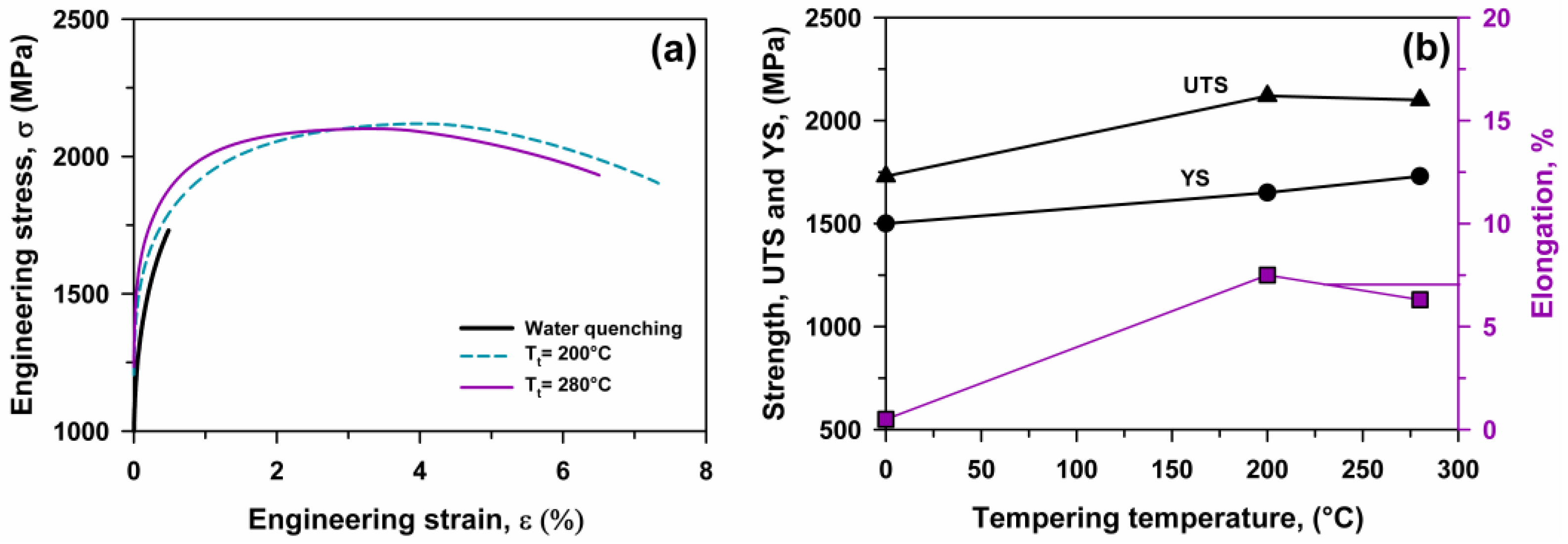
Engineering stress–strain curves are presented in Figure 10. After water quenching, the failure occurs immediately after yielding; the elongation-to-failure is 0.5%, and the YS and UTS are 1500 and 1730 MPa, respectively. Therefore, the quenched specimen exhibits intense work hardening after yielding. Tempering at 200 and 280 °C provides a strong increase in the ductility and strength, concurrently, due to work hardening after continuous yielding. After tempering at 200 °C, the YS, UTS and elongation-to-failure are 1640 MPa, 2120 MPa, and 7.3%, respectively. After tempering at 280 °C, the YS, UTS, and elongation-to-failure are 1730 MPa, 2100 Mpa, and 6.5%, respectively. Thus, the precipitation of η-Fe2C transition carbides provides a 15% increase in the YS, and the ductility increases by a factor of ~13. As a result, the PSE of ~1.5 × 10⁴ MPa·% is relatively high after tempering. The hardness of 55 HRC is nearly independent of tempering.

3.3.2. Q&P

Engineering stress–strain curves are presented in Figure 11a, and the effects of Tq on the YS, UTS, and elongation-to-failure are shown in Figure 11b. Continuous yielding followed by work hardening is observed for all Tq. At Tq ≤ 200 °C, the PLC effect appears as the rise in the flow stress, followed by a drop to or below the general stress level [41]. Increasing Tq from 140 to 250 °C leads to the increase in the elongation-to-failure from 17.5 to 21.4% and the decrease in the UTS from 1780 to 1580 MPa. The PSE > 3 × 10⁴ MPa·% is observed in the Tq range 140–250 °C (Figure 11c). The highest PSE value of 3.5 × 10⁴ MPa·% was achieved at Tq = 220 °C and correlates with fRA = 24% and fM1 > fM2. Thus, Q&P may increase the PSE value by a factor of more than 2 in comparison with low temperature tempering in Q&T treatment. An increase in the Tq from 260 to 300 °C leads to a drop in the ductility and PSE and an increase in the UTS. The fracturing of the specimen quenched at 300 °C occurs immediately after yielding (Figure 11a). Therefore, embrittlement occurs if the quenching temperature is >270 °C, and is associated with a high volume fraction of untempered martensite. A relatively high volume fraction of RA could not provide ductility if low-temperature martensite containing η-Fe2C transition carbides is lacking. Therefore, high ductility and PSE are achieved due to a balance between primary martensite, secondary martensite, and RA structural components. Solely fRA ≥ 5% is not sufficient for increased ductility. The steel with untempered martensite produced by Q&T treatment or Q&P processing with Tq > MS is brittle and the brittleness is independent of the presence of RA containing relatively low carbon, since at Tp = 400 °C no partitioning occurred due to the lack of primary martensite after quenching at Tq = 300 °C.
Hardness is nearly independent of Tq and increases remarkably at Tq > MS up to 58 HRC (Figure 11d). Thus, hardness values after Q&T and Q&P with Tq > MS are essentially the same.

3.4. PLC Band Behavior

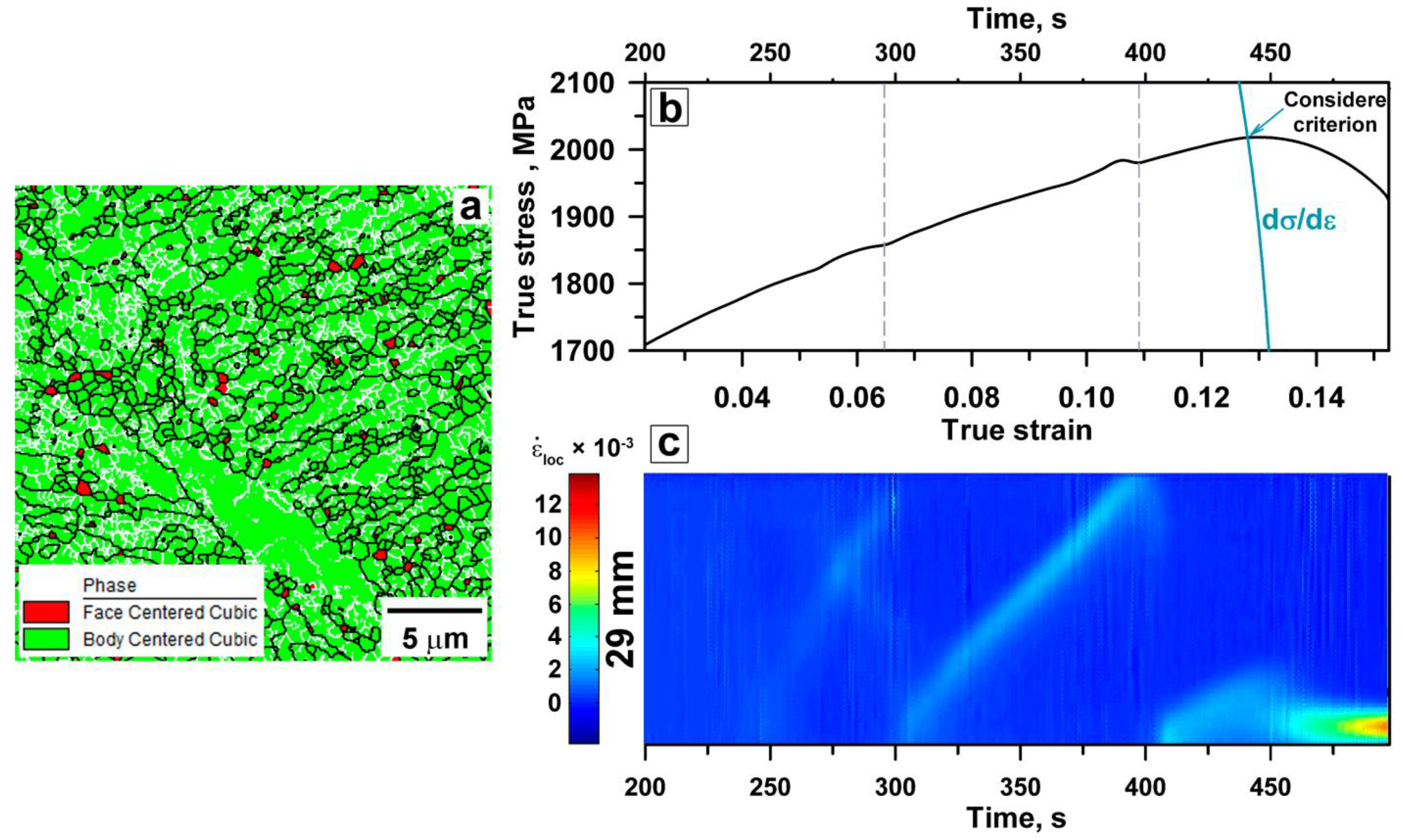
An EBSD study and X-ray data of the tensioned specimen in the neck area after failure showed that the volume fraction of RA does not exceed 3% (Figure 12a) and therefore, the volume fraction of RA decreases by a factor of ~12 under tension. These data support the statement about the easy (blocky RA → α′) transformation under tension [6,16]; the TRIP effect [10,18] provides good ductility and high PSE. The DIC method makes it possible to monitor the local strain distribution on the specimen’s surface during tension by correlating successive images of the speckle pattern. The local strain rate map (Figure 12c) and the corresponding sections of the deformation curve (Figure 12b) for the specimen after quenching at 160 °C show the localization of plastic deformation in the PLC bands [41], as indicated by the distribution of the local strain rate in the tensile direction. The first deformation band appears in the central region of the tensile specimen after attaining a critical strain of ~6% and propagates to the edge of the gauge section. The formation of a PLC band correlates with a flow stress jump of ~7 MPa, and the termination of the band propagation at the specimen edge correlates with a flow stress drop of ~6 MPa. A new PLC band nucleates at the bottom part of the tension specimen and this process is repeated until the Considère criterion dσ/dε = σ is met. Therefore, type A oscillation takes place at the work-hardening stage and uniform elongation is attributed to the propagation of PLC bands [41]. It is worth noting that a weak strain/strain rate localization takes place in the mobile PLC bands.
The onset of necking is attributed to the immobility of the PLC band and a strong increase in the degree of strain/strain rate localization after reaching the Considère strain (ε~0.13) [42]. Thus, the Considère criterion effectively describes the transition from a stable plastic flow to an unstable one. The localization of plastic deformation leads to the fracture. Similar mechanical behavior was reported for TRIP steels [42,43,44]. Thus, a high PSE value is achieved due to the TRIP effect during the tension and mobility of PLC bands lacking deformation localization up to achieving the Considère criterion.

4. Discussion

Inspection of the experimental data shows that Q&P processing provides a combination of the strength, ductility, and PSE of the present steel in accordance with the requirements for third-generation AHSS [1]. The role of RA in enhancing ductility and PSE after Q&T and Q&P processing is ambiguous. The steel exhibits high strength and sufficient ductility after low-temperature tempering almost without RA and is brittle after Q&P at Tq = 300 °C (see Section 3.3.2). Structural observation shows that the dislocation densities in martensite and RA are almost the same (see Section 3.2.2). It is apparent that RA may provide high elongation and PSE if its strength is close to the YS.
In order to calculate the overall YS of RA, we can use a linear combination of the strengthening mechanisms written as follows [12,45,46]:
YS = σ0 + σSS + σHP + σdisl,
where σ0 is the lattice friction stress of about 63.5 MPa in high purity austenite [46], σSS is the solid solution strengthening, σHP is the grain boundary strengthening, and σdisl is the dislocation strengthening. The solid solution strengthening (σSS) can be expressed using the following relationship [46]:
σSS = 356.5 × (wt.%C) + 20.1 × (wt.%Si) + 3.7 × (wt.%Cr) + 14.6 × (wt.%Mo)
The average concentrations of carbon in RA and σSS values are summarized in Table 3. It is seen that partitioning provides σSS ~ 600 MPa in the RA, and their strong strengthening takes place under the partitioning pass. Isothermal quenching provides a high volume fraction of RA in the present steel, and partitioning makes this phase “strong”.
The grain boundary strengthening (σHP) can be evaluated by the Hall–Petch type relationship [47,48,49,50,51,52]:
σHP = KHPD−0.5
where KHP is the Hall–Petch coefficient. KHP = 160 MPa × μm0.5 reported for austenitic steel [49] was taken for the present calculations. The size of the RA grain, determined from the misorientation map (Table 2), for different states averages D ~ 2.3 μm. Changing the grain size does not lead to significant changes in strengthening relative to the overall value. The contribution of σHP varies within 100 MPa, which is approximately 10% of the total strength.
Table 3. Effect of quenching temperature on the contributions of different strengthening mechanisms to the yield strength.
Tq, °CCRAρKAM, ×1014 m−2σSSσHPσdislσ0.2 of RA ( σ 0.2 R A ) , MPa YS, MPaΔYS, MPa
1401.3155.81575.8118.0331.91025.71350324.3
1601.3136.18575.1104.4342.31021.81350328.2
1801.46.30606.1103.3345.71055.11220164.9
2001.3836.22600.098.3343.41041.7112078.3
2201.3936.26603.6103.3344.51051.4108028.6
2501.5726.15667.4104.2341.411131060−53
The dislocation strengthening (σdisl) due to the high dislocation density (ρ) can be expressed by the Taylor-type relationship [12,49,50,51,52]:
σdisl = αMGbρ0.5,
where α is the dislocation strengthening factor of about 0.24 for materials with an fcc lattice [49,50,52], M denotes the Taylor factor, taken as 3.06 from misorientation maps, G is the shear modulus (=75 GPa [51]), b is the magnitude of the Burgers vector (=0.25 nm) [12,49,51,52], and ρ is the dislocation density. Despite the fact that the dislocation density determined by TEM shows higher values for the austenitic phase (ρ ~ 2 × 10¹⁵ m−2), since it takes into account dislocations of different signs, the ρ K A M ~ 6 × 10¹⁴ m−2 value, associated with internal stress fields, was used for the calculations. The dislocation strengthening calculated from the ρ K A M values provides the best fit to the experimental YS (Table 3). The contributions of different strengthening mechanisms to the overall strength of RA and YS of steel are summarized in Figure 13. It is seen that the superposition of high dislocation strengthening, originating from the intense plastic straining of RA during γ→α′ phase transformation under quenching, and the solid solution strengthening, enhanced by partitioning treatment, provides the high strength of the RA (Table 3). The role of grain boundary strengthening is minor for the blocky RA, but could give a significant contribution to the overall strength of RA for the film-like RA due to the fact that dimensions of this type of RA are ~20 times smaller than those of the blocky RA.
Table 4. Volume fractions of the primary martensite, secondary martensite, and RA calculated by Equation (4).
Tq, °CVolume Fraction of M1, %Volume Fraction of RA, %Volume Fraction of M2, %Contribution of M1 to YS, 1730·fM1 (MPa)Contribution of M2 to YS, 1500·fM2 (MPa)Contribution of RA to YS, σ 0.2 R A YS Calculated by Equation (1)
140771761332901741596
16072171112461651721583
18065221311251952321552
2005623219693152391523
2204524317784652521495
2502425514157652781458
In the present steel, the YS and strength of RA are nearly the same at Tq ≥ 220 °C, when fRA ≥ 24%, and the volume fraction of primary martensite is <50%. Obviously, the strength of RA controls the YS of the present steel with such a structure. At Tq ≤ 160 °C, the difference between the σ0.2 of RA and YS of the steel is higher than 300 MPa (Table 3). In order to evaluate the validity of Equation (1), we can take the strength of secondary martensite as equal to 1500 MPa, i.e., the YS of the steel after water quenching, and the strength of primary martensite equal to 1730 MPa, i.e., the YS of the steel after water quenching followed by tempering at 280 °C. It is worth noting that this approach is simplified due to the fact that the carbon content in the secondary martensite will be higher than 0.44 wt.% C in martensite after water quenching due to partitioning at 400 °C. The carbon content in primary martensite after Q&P processing is significantly smaller than that in martensite after tempering at 280 °C followed by water quenching due to partitioning at 400 °C and a significantly higher density of η-Fe2C transition carbides after Q&P processing. The values of strength of the primary martensite, secondary martensite, and RA and the overall YS calculated by Equation (1) are shown in Table 4. It is seen that the composite law (Equation (1)) gives a strong overestimation of YS at Tq ≥ 180 °C and, therefore, the use of this law to predict YS in Q&P with multiphase structure is ambiguous. At the same time, at Tq ≤ 160 °C, the difference between the calculated YS and experimental YS is relatively small and could be attributed to the low carbon content in the primary martensite as compared to the low-temperature-tempered martensite. It is apparent that the composite law (Equation (1)) could be valid if there is a dominant phase, and the strengths of other phases are close to the strength of this dominant phase.

5. Conclusions

Q&T treatment with tempering temperatures of 200 and 280 °C ensures the formation of a martensite structure with high dislocation density and η-Fe2C transition carbides. The volume fraction of retained austenite is negligible (~0.7). After water quenching, the failure occurs immediately after yielding. Tempering at 200 and 280 °C provides a strong increase in ductility (~7%). The PSE is ~15 GPa·%.
The Fe-0.44C steel processed by Q&P shows the striking PSE > 30 GPa·% and yield stress > 1000 MPa. The superior combination of strength and plasticity is attributed to the high volume fraction of retained austenite with a blocky shape and its strength of ~1000 MPa. The origin of the high yield stress of retained austenite is associated with carbon enrichment (~1.3wt.%) and the high density of lattice dislocations (~6 × 10¹⁴ m−2) in this phase. Almost full transformation of retained austenite into martensite under tension at room temperature leads to the significant work hardening and relatively high ductility. The onset of the necking is associated with immobility of the Portevin–Le Chatelier bands and described by the Considère criterion, dσ/dε = σ.
The strength of retained austenite controls the YS of the present steel when fRA ≥ 24%. Superposition of high dislocation strengthening, originating from the intense plastic straining of retained austenite during the γ→α′ phase transformation under quenching, the solid solution strengthening, enhanced by partitioning treatment, and grain boundary strengthening provides the high strength of the retained austenite > 1000 MPa.

Author Contributions

Conceptualization, R.M. and R.K.; methodology, R.M. and Y.B.; validation, Y.B., S.G. and O.V.; formal analysis, Y.B.; investigation, R.M., Y.B., S.G., O.V., T.K. and R.K.; resources, R.K.; data curation, Y.B. and R.M.; writing—original draft preparation, R.M. and R.K.; writing—review and editing, Y.B. and R.M.; visualization, R.M.; supervision, R.K.; project administration, R.K.; funding acquisition, R.K. All authors have read and agreed to the published version of the manuscript.

Funding

This research was funded by the Ministry of Science and Higher Education of the Russian Federation, grant number 075-15-2021-572.

Institutional Review Board Statement

Not applicable.

Informed Consent Statement

Not applicable.

Data Availability Statement

Not applicable.

Acknowledgments

The studies were carried out on the equipment of the Joint Scientific Center for Technologies and Materials of Belgorod State National Research University, which was supported by the Ministry of Science and Higher Education of the Russian Federation under contract No. 075-15-2021-690 (unique identifier RF—2296.61321X0030).

Conflicts of Interest

The authors declare no conflict of interest.

References

  1. Fonstein, N. Advanced High Strength Sheet Steels; Springer International Publishing: Cham, Switzerland, 2015; ISBN 978-3-319-19164-5. [Google Scholar]
  2. Zhang, K.; Liu, P.; Li, W.; Guo, Z.; Rong, Y. Ultrahigh Strength-Ductility Steel Treated by a Novel Quenching–Partitioning–Tempering Process. Mater. Sci. Eng. A 2014, 619, 205–211. [Google Scholar] [CrossRef]
  3. An, B.; Zhang, C.; Gao, G.; Gui, X.; Tan, Z.; Misra, R.D.K.; Yang, Z. Experimental and Theoretical Analysis of Multiphase Microstructure in a Newly Designed MnSiCrC Quenched and Partitioned Steel to Promote Bainitic Transformation: The Significant Impact on Mechanical Properties. Mater. Sci. Eng. A 2019, 757, 117–123. [Google Scholar] [CrossRef]
  4. Zurnadzhy, V.I.; Efremenko, V.G.; Wu, K.M.; Petryshynets, I.; Shimizu, K.; Zusin, A.M.; Brykov, M.N.; Andilakhai, V.A. Tailoring Strength/Ductility Combination in 2.5 Wt% Si-Alloyed Middle Carbon Steel Produced by the Two-Step Q-P Treatment with a Prolonged Partitioning Stage. Mater. Sci. Eng. A 2020, 791, 139721. [Google Scholar] [CrossRef]
  5. Chen, K.; Jiang, Z.; Liu, F.; Li, H.; Kang, C.; Zhang, W.; Wang, A. Achievement of High Ductility and Ultra-High Strength of V-Nb Microalloyed Spring Steel by Austempered Multiphase Microstructure. Metall. Mater. Trans. A 2020, 51, 3565–3575. [Google Scholar] [CrossRef]
  6. Dong, X.X.; Shen, Y.F.; Jia, N.; Zhu, Y.T. Improving Mechanical Properties and Retained-Austenite Stability of a Medium Carbon Q&P Steel by Adjusting Phase Ratio. Mater. Sci. Eng. A 2022, 833, 142580. [Google Scholar] [CrossRef]
  7. Kusakin, P.S.; Kaibyshev, R.O. High-Mn twinning-induced plasticity steels: Microstructure and mechanical properties. Rev. Adv. Mater. Sci. 2016, 44, 326–360. [Google Scholar]
  8. De Cooman, B.C.; Estrin, Y.; Kim, S.K. Twinning-Induced Plasticity (TWIP) Steels. Acta Mater. 2018, 142, 283–362. [Google Scholar] [CrossRef]
  9. Dai, Z.; Chen, H.; Ding, R.; Lu, Q.; Zhang, C.; Yang, Z.; Zwaag, S. Fundamentals and Application of Solid-State Phase Transformations for Advanced High Strength Steels Containing Metastable Retained Austenite. Mater. Sci. Eng. R 2021, 143, 100590. [Google Scholar] [CrossRef]
  10. Zhao, J.; Jiang, Z. Thermomechanical Processing of Advanced High Strength Steels. Prog. Mater. Sci. 2018, 94, 174–242. [Google Scholar] [CrossRef]
  11. Bouquerel, J.; Verbeken, K.; Cooman, B.C.D. Microstructure-Based Model for the Static Mechanical Behaviour of Multiphase Steels. Acta Mater. 2006, 54, 1443–1456. [Google Scholar] [CrossRef]
  12. Seo, E.J.; Cho, L.; Estrin, Y.; De Cooman, B.C. Microstructure-Mechanical Properties Relationships for Quenching and Partitioning (Q&P) Processed Steel. Acta Mater. 2016, 113, 124–139. [Google Scholar] [CrossRef]
  13. Speer, J.; Matlock, D.K.; De Cooman, B.C.; Schroth, J.G. Carbon Partitioning into Austenite after Martensite Transformation. Acta Mater. 2003, 51, 2611–2622. [Google Scholar] [CrossRef]
  14. Speer, J.G. Phase Transformations in Quenched and Partitioned Steels in Diffusionless Transformation, High Strength Steels, Modeling and Advanced Analytical Techniques; Pereloma, E., Edmonds, D.V., Eds.; Woodhead Publishing Ltd.: Cambridge, UK, 2012; Volume 2, pp. 247–270. [Google Scholar]
  15. Moor, E.D.; Speer, J.G.; Matlock, D.K.; Kwak, J.-H.; Lee, S.-B. Effect of Carbon and Manganese on the Quenching and Partitioning Response of CMnSi Steels. ISIJ Int. 2011, 51, 137–144. [Google Scholar] [CrossRef] [Green Version]
  16. Xiong, X.C.; Chen, B.; Huang, M.X.; Wanga, J.F.; Wang, L. The Effect of Morphology on the Stability of Retained Austenite in a Quenched and Partitioned Steel. Scr. Mater. 2013, 68, 321–324. [Google Scholar] [CrossRef]
  17. Shen, Y.F.; Qiu, L.N.; Sun, X.; Zuo, L.; Liaw, P.K.; Raabe, D. Effects of Retained Austenite Volume Fraction, Morphology, and Carbon Content on Strength and Ductility of Nanostructured TRIP-Assisted Steels. Mater. Sci. Eng. A 2015, 636, 551–564. [Google Scholar] [CrossRef] [Green Version]
  18. Soleimani, M.; Kalhor, A.; Mirzadeh, H. Transformation-Induced Plasticity (TRIP) in Advanced Steels: A Review. Mater. Sci. Eng. A 2020, 795, 140023. [Google Scholar] [CrossRef]
  19. Yan, S.; Liu, X.; Liu, W.J.; Liang, T.; Zhang, B.; Liu, L.; Zhao, Y. Comparative Study on Microstructure and Mechanical Properties of a C-Mn-Si Steel Treated by Quenching and Partitioning (Q&P) Processes after a Full and Intercritical Austenitization. Mater. Sci. Eng. A 2017, 684, 261–269. [Google Scholar] [CrossRef]
  20. Liu, L.; Li, H.; Xu, H.; Dai, X.; Tian, Y.; Chen, L. The Effect of Partitioning Temperature on Residual Austenite and Mechanical Properties of Q&P High Strength Steel during the Continuous Annealing Process. Metals 2022, 12, 2165. [Google Scholar] [CrossRef]
  21. Nakada, N.; Ishibashi, Y.; Tsuchiyama, T.; Takaki, S. Self-Stabilization of Untransformed Austenite by Hydrostatic Pressure via Martensitic Transformation. Acta Mater. 2016, 110, 95–102. [Google Scholar] [CrossRef]
  22. Gao, G.; Gao, B.; Gui, X.; Hu, J.; He, J.; Tan, Z.; Bai, B. Correlation between Microstructure and Yield Strength of As-Quenched and Q&P Steels with Different Carbon Content (0.06–0.42 Wt%C). Mater. Sci. Eng. A 2019, 753, 1–10. [Google Scholar] [CrossRef]
  23. HajyAkbary, F.; Sietsma, J.; Miyamoto, G.; Kamikawa, N.; Petrov, R.H.; Furuhara, T.; Santofimia, M.J. Analysis of the Mechanical Behavior of a 0.3C-1.6Si-3.5Mn(Wt%) Quenching and Partitioning Steel. Mater. Sci. Eng. A 2016, 677, 505–514. [Google Scholar] [CrossRef]
  24. Lebedkina, T.A.; Lebyodkin, M.A.; Chateau, J.-P.; Jacques, A.; Allain, S. On the Mechanism of Unstable Plastic Flow in an Austenitic FeMnC TWIP Steel. Mater. Sci. Eng. A 2009, 519, 147–154. [Google Scholar] [CrossRef]
  25. Hirsh, P.B.; Howie, A.; Nicholson, R.B.; Pashley, D.W.; Whelan, M.J. Electron Microscopy of Thin Crystals; Butterworths: London, UK, 1965. [Google Scholar]
  26. Zhilyaev, A.; Shakhova, I.; Belyakov, A.; Kaibyshev, R.; Langdon, T.G. Wear Resistance and Electroconductivity in Copper Processed by Severe Plastic Deformation. Wear 2013, 305, 89–99. [Google Scholar] [CrossRef]
  27. Niessen, F.; Nyyssönen, T.; Gazder, A.A.; Hielscher, R. Parent Grain Reconstruction from Partially or Fully Transformed Microstructures in MTEX. J. Appl. Crystallogr. 2022, 55, 180–194. [Google Scholar] [CrossRef] [PubMed]
  28. Miyamoto, G.; Iwata, N.; Takayama, N.; Furuhara, T. Mapping the Parent Austenite Orientation Reconstructed from the Orientation of Martensite by EBSD and Its Application to Ausformed Martensite. Acta Mater. 2010, 58, 6393–6403. [Google Scholar] [CrossRef]
  29. Cullity, B.D. Elements of X-Ray Diffraction. In Addison-Wesley Series in Metallurgy and Materials, 2nd ed.; Addison-Wesley Pub. Co.: Boston, MA, USA, 1978; ISBN 978-0-201-01174-6. [Google Scholar]
  30. Vandijk, N.; Butt, A.; Zhao, L.; Sietsma, J.; Offerman, S.; Wright, J.; Vanderzwaag, S. Thermal Stability of Retained Austenite in TRIP Steels Studied by Synchrotron X-Ray Diffraction during Cooling. Acta Mater. 2005, 53, 5439–5447. [Google Scholar] [CrossRef]
  31. Ranjan, R.; Beladi, H.; Hodgson, P.D.; Singh, S.B. The Mechanical Properties of Low Alloy TRIP-Aided Steel: The Role of Retained Austenite. Met. Mater. Trans. A 2021, 52, 4649–4663. [Google Scholar] [CrossRef]
  32. Tkachev, E.; Borisov, S.; Belyakov, A.; Kniaziuk, T.; Vagina, O.; Gaidar, S.; Kaibyshev, R. Effect of Quenching and Tempering on Structure and Mechanical Properties of a Low-Alloy 0.25C Steel. Mater. Sci. Eng. A 2023, 868, 144757. [Google Scholar] [CrossRef]
  33. Hidalgo, J.; Celada-Casero, C.; Santofimia, M.J. Fracture Mechanisms and Microstructure in a Medium Mn Quenching and Partitioning Steel Exhibiting Macrosegregation. Mater. Sci. Eng. A 2019, 754, 766–777. [Google Scholar] [CrossRef]
  34. Carpio, M.; Calvo, J.; García, O.; Pedraza, J.P.; Cabrera, J.M. Heat Treatment Design for a QP Steel: Effect of Partitioning Temperature. Metals 2021, 11, 1136. [Google Scholar] [CrossRef]
  35. Bagliani, E.P.; Santofimia, M.J.; Zhao, L.; Sietsma, J.; Anelli, E. Microstructure, Tensile and Toughness Properties after Quenching and Partitioning Treatments of a Medium-Carbon Steel. Mater. Sci. Eng. A 2013, 559, 486–495. [Google Scholar] [CrossRef]
  36. Huyghe, P.; Malet, L.; Caruso, M.; Georges, C.; Godet, S. On the Relationship between the Multiphase Microstructure and the Mechanical Properties of a 0.2C Quenched and Partitioned Steel. Mater. Sci. Eng. A 2017, 701, 254–263. [Google Scholar] [CrossRef]
  37. Peng, F.; Xu, Y.; Gu, X.; Wang, Y.; Liu, X.; Li, J. The Relationships of Microstructure-Mechanical Properties in Quenching and Partitioning (Q&P) Steel Accompanied with Microalloyed Carbide Precipitation. Mater. Sci. Eng. A 2018, 723, 247–258. [Google Scholar] [CrossRef]
  38. Pashangeh, S.; Somani, M.C.; Banadkouki, S.S.G.; Zarchi, H.R.K.; Kaikkonen, P.; Porter, D.A. On the decomposition of austenite in a high-silicon medium-carbon steel during quenching and isothermal holding above and below the Ms temperature. Mater. Charact. 2020, 162, 110224. [Google Scholar] [CrossRef]
  39. Kitahara, H.; Ueji, R.; Tsuji, N.; Minamino, Y. Crystallographic Features of Lath Martensite in Low-Carbon Steel. Acta Mater. 2006, 54, 1279–1288. [Google Scholar] [CrossRef]
  40. Koistinen, D.P.; Marburger, R.E. A General Equation Prescribing the Extent of the Austenite-Martensite Transformation in Pure Iron-Carbon Alloys and Plain Carbon Steels. Acta Metall. 1959, 7, 59–60. [Google Scholar] [CrossRef]
  41. Yuzbekova, D.; Mogucheva, A.; Zhemchuzhnikova, D.; Lebedkina, T.; Lebyodkin, M.; Kaibyshev, R. Effect of Microstructure on Continuous Propagation of the Portevin–Le Chatelier Deformation Bands. Int. J. Plast. 2017, 96, 210–226. [Google Scholar] [CrossRef]
  42. Choi, J.H.; Jo, M.C.; Lee, H.; Zargaran, A.; Song, T.; Sohn, S.S.; Kim, N.J.; Lee, S. Cu Addition Effects on TRIP to TWIP Transition and Tensile Property Improvement of Ultra-High-Strength Austenitic High-Mn Steels. Acta Mater. 2019, 166, 246–260. [Google Scholar] [CrossRef]
  43. Li, Z.C.; Ding, H.; Misra, R.D.K.; Cai, Z.H. Deformation Behavior in Cold-Rolled Medium-Manganese TRIP Steel and Effect of Pre-Strain on the Lüders Bands. Mater. Sci. Eng. A 2017, 679, 230–239. [Google Scholar] [CrossRef] [Green Version]
  44. Torganchuk, V.; Belyakov, A.; Kaibyshev, R. On the Transformation-Induced Plasticity of a Medium-Manganese Steel. Mater. Lett. 2021, 304, 130599. [Google Scholar] [CrossRef]
  45. Baker, T.N. Yield, Flow and Fracture of Polycrystals; Applied Science Publishers: London, UK, 1983. [Google Scholar]
  46. Gavriljuk, V.G.; Berns, H. High Nitrogen Steels: Structure, Properties, Manufacture, Applications; Springer: Berlin/Heidelberg, Germany, 1999; ISBN 978-3-642-08567-3. [Google Scholar]
  47. Hall, E.O. The Deformation and Ageing of Mild Steel: III Discussion of Results. Proc. Phys. Society. Sect. B 1951, 64, 747–753. [Google Scholar] [CrossRef]
  48. Petch, N.J. The Cleavage Strength of Polycrystals. J. Iron Steel Inst. 1953, 174, 25–28. [Google Scholar]
  49. Odnobokova, M.; Belyakov, A.; Enikeev, N.; Kaibyshev, R.; Valiev, R.Z. Microstructural Changes and Strengthening of Austenitic Stainless Steels during Rolling at 473 K. Metals 2020, 10, 1614. [Google Scholar] [CrossRef]
  50. Malopheyev, S.; Kulitskiy, V.; Kaibyshev, R. Deformation Structures and Strengthening Mechanisms in an Al Mg Sc Zr Alloy. J. Alloy. Compd. 2017, 698, 957–966. [Google Scholar] [CrossRef]
  51. Odnobokova, M.V.; Belyakov, A.N.; Dolzhenko, P.D.; Kostina, M.V.; Kaibyshev, R.O. On the Strengthening Mechanisms of High Nitrogen Austenitic Stainless Steels. Mater. Lett. 2023, 331, 133502. [Google Scholar] [CrossRef]
  52. Kusakin, P.; Belyakov, A.; Haase, C.; Kaibyshev, R.; Molodov, D. Microstructure Evolution and Strengthening Mechanisms of Fe–23Mn–0.3C–1.5Al TWIP Steel during Cold Rolling. Mater. Sci. Eng. A 2014, 617, 52–60. [Google Scholar] [CrossRef]
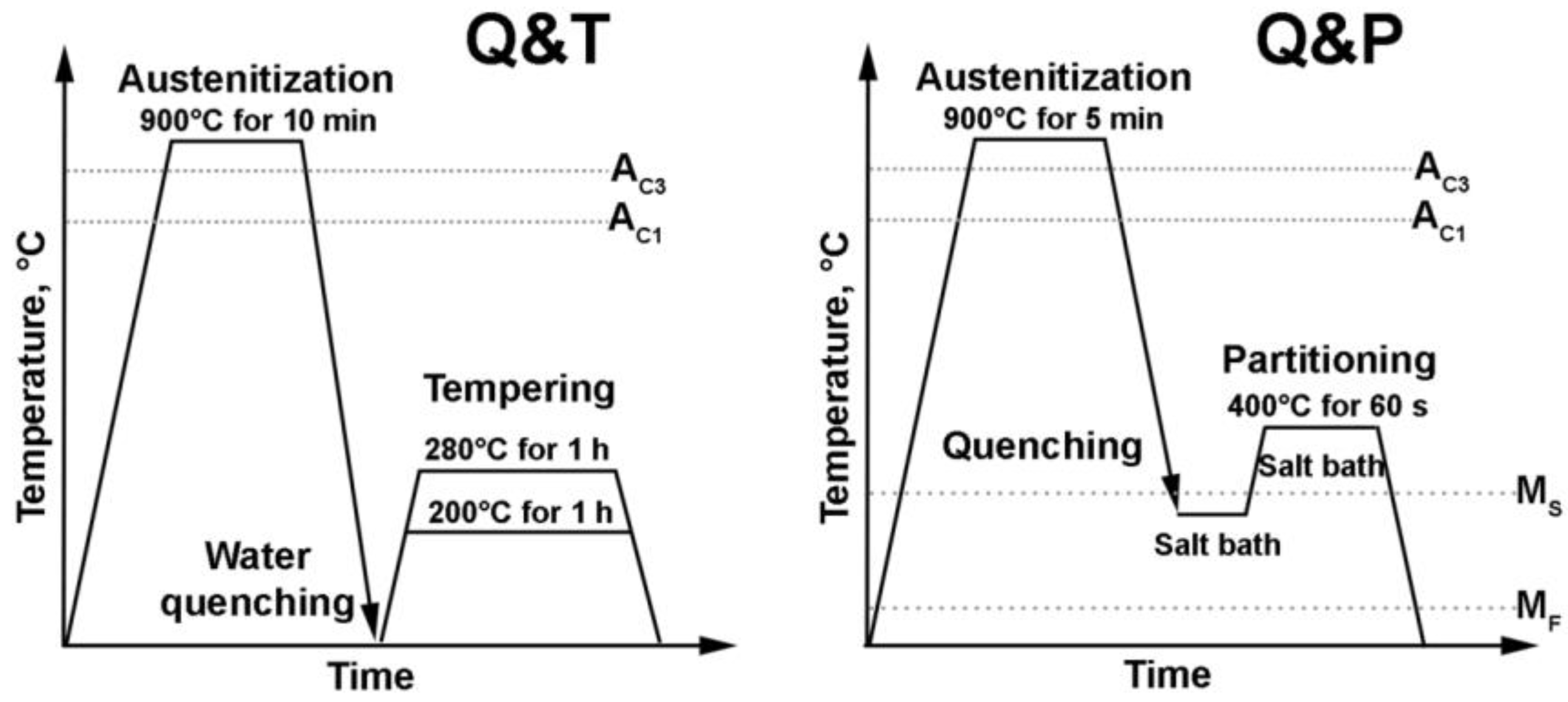
Figure 1. Schematic graphs of Q&T and Q&P treatments.
Metals 13 00689 g001
Figure 2. Dilatation curves obtained during heating (a) and cooling (b).
Metals 13 00689 g002
Figure 3. EBSD analysis of the as-quenched steel: (a) Misorientation map showing HABs of the reconstructed austenite grains and packets; (b) misorientation map of reconstructed PAGs with their boundaries in black; (c) identification of packets in a PAG indicated as A in (a) and {001} pole figure showings (0 0 1) [1 0 0] orientations that maintain the K–S orientation relationship; identification of packets in PAGs; (d) TEM observation of the steel subjected to water quenching and tempering at 280 °C, with the insert indicating the presence of transition η-carbide.
Metals 13 00689 g003
Figure 4. SEM micrographs of the Fe-0.44C steel after quenching at 140 °C (a), 160 °C (b), 250 °C (c), 300 °C (d).
Metals 13 00689 g004
Figure 5. EBSD analysis of the Fe-0.44C steel after quenching at 140 °C (a1a4), 160 °C (b1b4), 200 °C (c1c4), and 250 °C (d1d4), RA is emphasized by red color (column 2), KAM map (columns 3, 4). BCC—Body Centered Cubic; FCC—Face Centered Cubic.
Metals 13 00689 g005
Figure 6. EBSD analysis of the steel subjected to Q&P processing with quenching in a salt bath at temperatures of 160 °C (a1a3), 200 °C (b1b3), and 250 °C (c1c3): (column 1) misorientation map showing HABs of the reconstructed austenite grains and packets; (column 2) identification of packets in PAGs; (column 3) {001} pole figure showings (0 0 1) [1 0 0] orientations that maintain the K–S orientation relationship.
Metals 13 00689 g006
Figure 7. Typical microstructure of the steel after quenching at 160 °C: TEM micrograph of structure (a); TEM micrograph of RA (dark field) (b); TEM micrograph of η-carbide within the martensitic lath (c).
Metals 13 00689 g007
Figure 8. Effect of quenching temperature on the volume fraction of RA (a); typical XRD spectra after quenching at 160 °C (b); calculated Tq-dependence of the phase fraction of austenite and secondary martensite, assuming full C partitioning into austenite prior to the final quenching (c).
Metals 13 00689 g008
Figure 9. Phase distribution according to EBSD analysis from the center to the surface of the Fe-0.44C steel after quenching at 160 °C.
Metals 13 00689 g009
Figure 10. Typical engineering stress–strain curves (a), effect of tempering temperature on the tensile properties (YS, UTS, elongation) (b) of the Fe-0.44C steel.
Metals 13 00689 g010
Figure 11. Typical engineering stress–strain curves (a), effect of quenching temperature on the tensile properties (the YS, UTS, elongation) (b), PSE (c), and hardness (d) of the Fe-0.44C steel.
Metals 13 00689 g011
Figure 12. EBSD analysis of the Fe-0.44C steel after the tensile test (a) and the corresponding sections of the true stress-time curve (b) and the local strain rate map (c) of the Fe-0.44C steel after quenching at 160 °C. Color legend shows the local strain-rate scale.
Metals 13 00689 g012
Figure 13. Comparison between the calculated strength of RA and the experimentally obtained YS for Q&P-processed Fe-0.44C steel. The contribution of strengthening mechanisms in overall YS is marked with different colors.
Metals 13 00689 g013
Table 1. Critical points of the Fe-0.44C steel.
MethodAc1, °CAc3, °CMS, °CMF, °C
Thermo-Calc729798
Dilatometry curve76085727051
Table 2. Effect of quenching temperature on the KAM value of RA/martensite and the average size of RA.
Tq, °CKAM Value of RA, °KAM Value of Martensite, °Average Grain Size of RA, μm
1400.560.531.84
1600.590.522.35
1800.600.512.4
2000.590.572.65
2200.60.592.4
2500.590.572.36
Disclaimer/Publisher’s Note: The statements, opinions and data contained in all publications are solely those of the individual author(s) and contributor(s) and not of MDPI and/or the editor(s). MDPI and/or the editor(s) disclaim responsibility for any injury to people or property resulting from any ideas, methods, instructions or products referred to in the content.