Review

A Review on the Corrosion and Fatigue Failure of Gas Turbines

by
Leila Fathyunes
1 and
M. A. Mohtadi-Bonab
2,*
1
Department of Materials Science and Engineering, University of Bonab, Bonab 5551395133, Iran
2
Department of Mechanical Engineering, University of Bonab, Bonab 5551395133, Iran
*
Author to whom correspondence should be addressed.
Metals 2023, 13(4), 701; https://doi.org/10.3390/met13040701
Submission received: 27 February 2023 / Revised: 28 March 2023 / Accepted: 30 March 2023 / Published: 3 April 2023
(This article belongs to the Special Issue Failure and Degradation of Metals)

Abstract

:
Since gas turbines are used in airplanes, ship engines and power plants, they play a significant role in providing sustainable energy. Turbines are designed for a certain lifetime according to their operating conditions and the failure mechanisms they deal with. However, most of them experience unexpected and catastrophic failure as a result of synergistic effects of more than one damage mechanism. One of the main causes of failure in turbines is corrosion fatigue, which results from the combination of cyclic loads and corrosive environments. In the current review paper, an attempt has been made to investigate the damages related to corrosion and fatigue in turbines such as fatigue corrosion, hot corrosion and oxidation, thermomechanical fatigue, emphasizing their synergistic effect. In this regard, the mechanism of fatigue crack initiation and growth in a corrosive environment is also taken into consideration. Moreover, a summary of the results reported in the literature regarding the influence of the loading conditions, characteristics of the corrosive environment and properties of the turbine materials on this failure is presented. Finally, common methods of dealing with corrosion fatigue damage, including surface treatment and cathodic protection, are briefly reviewed.

1. Introduction

Sustainable energy supply is one of the current critical challenges, and in this regard, gas turbines have established themselves as one of the reliable energy sources [1]. Gas tur-bines are widely used to generate electricity from the combustion of fossil fuels [2,3]. Although clean renewable sources of energy are of interest, the intermittent nature of them can cause instability in the energy production [4]. Therefore, a significant part of the required electricity is still produced by gas turbines. In addition, the increasing progress in the field of the gas turbine industry has made it possible to use biofuels such as bio-ethanol, bio-methanol, synthetic gas, hydrogen and so on instead of fossil fuels [5,6].
The gas turbines convert the thermal energy from fuel combustion into the mechanical energy which is used to drive electric generators [7,8]. As is seen from Figure 1, they are composed of three main sections, called compressor, combustor, and turbine. Ambient air enters the gas turbine at the compressor inlet, and its pressure increases during compression. This section contains alternating rows of static airfoils known as vanes and rotating airfoils known as blades. The compressed air is then drawn to the combustion section, where ignition of the air and fuel mixture further increases the temperature. The gas produced during the combustion is expanded in the turbine section back to atmospheric pressure. The turbine section, similar to the compressor, contains alternating rows of vanes and blades. The expanded gas rotates the turbine blades and this rotation transfers into the external generator. The produced energy is used to power aircraft, trains, ships and electrical generators [9,10,11].
It has been reported that increasing the inlet temperature raises the gas turbine efficiency [13,14,15]. The engine components which are exposed to hot gas are the nozzles, disks and rotor blades [16,17]. Exposure to high temperatures and harsh environments causes the turbine components to suffer from oxidation and hot corrosion [18,19,20]. This is further complicated for marine applications by the aggressivity of various halides contained in seawater [21,22]. Furthermore, the rotating blades bear the centrifugal force as well as the bending and torsion stresses caused by the steam flow pressure. These complex alternating stresses make blades prone to unexpected fatigue failure much earlier than the designed lifetime [23,24,25]. Obviously, in most cases, failure is due to the interaction of more than one mechanism, and hence, considering single-factor damage will not satisfy the design requirements [26]. Corrosion fatigue, stress corrosion cracking, erosion and creep are addressed as great concerns in turbine components [27,28,29].
The early fracture of blades is the main reason for the turbine failure which causes unplanned shutdowns for long periods and financial losses [30,31]. One major disadvantage is that all blades in the whole system should be replaced if one of them fails. Hence, it is important to analyze the failure and the reliability of the blade to predict service lifetime [32]. The corrosion fatigue is found to be one of the important failure mechanisms in turbines [33,34,35,36]. A decrease in the allowable stress limit as cyclic stresses are imposed in a corrosive environment is a consequence of corrosion fatigue failure. In fact, the impact of corrosion at the surface reduces the time required for fatigue crack nucleation [37,38]. Fatigue crack growth is also accelerated by corrosion. Since corrosion is both time and temperature dependent, two important parameters that control the contribution of corrosion to fatigue failure include the corrosion rate and the time available for the corrosion damage per cycle [39]. Generally, failure caused by corrosion fatigue is affected by loading conditions, corrosive environments, and material properties [40,41]. The materials used for the turbine components, such as blades, vanes, disks, etc., must maintain their strength at high temperatures and be resistant to oxidation, fatigue, corrosion and erosion [9]. Martensitic stainless steels, high-strength low-alloy (HSLA) steels and nickel-based superalloys are dominantly used for turbine components [42,43,44,45]. Some examples of Ni-based superalloys are Inconel 718, FGH95, ME-16, RR1000, IN-100, Udimet 720LI, Nimonic 80A, Inconel 825, Nimonic C-263, Nimonic-75, and Nimonic-105 [32].
So far, numerous research studies have focused on corrosion and fatigue failures, and the summary of several studies is presented in Table 1. This confirms that this subject is an attractive and open field of research. The main purpose of the present paper is to provide a review of studies conducted in the field of fatigue and corrosion of the gas turbines.

2. Corrosion Fatigue

According to statistics, low-pressure blades are more prone to corrosion fatigue failure than those of high and intermediate pressure [33,36,53]. As the temperature falls below 100 °C at the end-region of the turbine, steam can easily condense on low-pressure last-stage blades, and the corrosive elements such as Cl and S in steam can form corrosive electrolytes in combination with water, leading to localized pitting corrosion [54,55,56]. This problem can be aggravated in the case of coastal power plants and plants with outage periods at night. The presence of chloride ions in seawater and increases in oxygen in the system during the outage period could intensify the pitting corrosion [57].
Localized corrosion as the most dangerous type of corrosion occurs mainly in the phase transition zone (PTZ), where steam condenses during its passage through the saturation line [30]. The pits raise the stress level locally, and cracks usually start from these sites and propagate under dynamic loading, eventually leading to sudden fractures [58,59]. Typically, appearance of the fracture surface consists of two distinct regions. The region, including fatigue striations, corresponds to the fatigue crack growth stage, and the rougher region relates to the final rapid fracture stage [60]. Mokaberi et al. investigated the failure analysis of the gas compressor blade made of GTD 450 stainless steel which failed after working for about 34,000 h in seawater. SEM micrograph in Figure 2a shows that the corrosion pit is surrounded by several micro cracks and the pits are existance in the fracture surface in Figure 2b [61]. Rajabinezhad et al. came to the conclusion that corrosion fatigue failure occurs mainly at the root of the turbine blades [32]. Ziegler et al. also reported that the corrosion pits formed on the tail of the blade are a source of stress concentration, which in turn accelerates damage initiation [62]. Moreover, the metallurgical assessment and chemical analysis by Adnyana revealed that the corrosion fatigue was the main cause for failure of the low-pressure last-stage blades made of AISI 422 martensitic stainless steel after only a few years in service. The fatigue crack was initiated from the pits and propagated in the tangential direction towards the edge of the blade, where the final fracture occurred [63].
At the end, it is worth noting that owing to cost, capacity of the test machine and ability to consider various variables, the majority of the studies on corrosion fatigue behavior are usually conducted using small compact tension or notched samples under corrosive conditions [64].

3. Hot Corrosion Fatigue

Nickel-based superalloys, owing to having acceptable resistance to degradation at high temperatures and fatigue, are usually employed in the compressor and turbine components [65,66]. However, exposure of the turbine components to high-chloride salts ingested from the air around marine and desert areas, as well as sulphur contaminants of cheap fuels, causes their premature failure [67,68,69]. The surface oxidation is an early sign of hot corrosion, which normally occurs at the hot components of turbine, especially nozzles, rotor blades and vanes [70,71,72].
Hot corrosion is commonly divided into Type I and Type II. Type I usually occurs in the temperature range of 850–950 °C, depending on the alloy composition. It initially starts by attacking the oxide protective layer through deposition of alkali salts on the surface of turbine components. Sodium sulphate is a well-known deposit which becomes liquid at high temperature. Moreover, other impurities can combine with sodium sulphate to form a more aggressive eutectic mixture. The sulphur then enters inward to react with elements from the substrate such as Cr, Al and Ti, resulting in the depletion of the alloying elements and formation of a porous scale [12,73,74]. Type II hot corrosion also typically occurs when the temperature is in the range of 650–800 °C and results in pitting. A significant partial pressure of SO3 in the gaseous phase is required for this type of hot corrosion [12,74]. In fact, diffusion of Ni from the substrate outwards and its dissolution in the liquid sulphate phase at the surface causes the discontinuity of the protective oxide layer, leading to pitting damage [75].
In conventional fatigue, cyclic loads introduce slip bands, leading to local plastic deformation accumulation and generation of micropores. The fatigue crack initiates from these pores and propagates as the stress intensity increases from threshold value [76,77,78]. When hot corrosion combines with a cyclic stress, it can contribute to both crack initiation through corrosion pitting, and propagation of fatigue crack [51,79]. It is believed that hot corrosion can be assisted by stress of sufficient magnitude as rupture of oxide surface layer by cyclic loading allows diffusion of sulphur inward alloy, resulting in oxidation and de-cohesion of grain boundary [80,81]. Consequently, the hot corrosion can change the crack propagation mode from transgranular to intergranular [79,82].
Mahobia et al. examined the corrosion fatigue behavior of the salt-coated superalloy IN718 at 650 °C. The results showed that the salt coating in both type of Na2SO4 + NaCl and Na2SO4 + NaCl + V2O5 accelerates the hot corrosion fatigue. Figure 3 depicts a possible mechanism for initiation and growth of fatigue cracks. As is seen from this figure, a dual-oxide scale forms on the surface during hot corrosion along with pits at the interface of the inner layer and substrate. Then, cracks initiate mostly from the bottom of corrosion pits under cyclic strain and propagate in a mixed transgranular/intergranular mode. At high strain amplitude, the number of slip bands increases to accommodate the large plastic strain impinging on weak grain boundaries, resulting in extensive crack-initiation sites with an intergranular mode [83].
Brooking et al. studied hot corrosion fatigue behavior of the single-crystal superalloy CMSX-4 pre-corroded for 500 h with a 1.25 or 5 µg/cm2/h flux and subjected to 550 °C under tensile unreversed trapezoidal load. They found a transition of fracture plane from {100} to {111}, possibly due to corrosion, along with the environmental oxidation markings on the fracture face (see Figure 4). Moreover, an increase in the dwell period shortened the fatigue life, which was related to time-dependent crack tip oxidation [51].
Gabb et al. investigated the effect of hot corrosion at 700 °C on the fatigue life of the superalloy ME3 and found that corrosion pits reduced the fatigue life by up to 98%. The chemical composition analysis of the corrosion products on pit cross section demonstrated that hot corrosion type II had occurred [84].
Mousavinia et al. analyzed the failure of a rotating blade from the hot section of a gas turbine. The blades were made from Nimonic-105, and their working temperature was in the range of 700–850 °C. Figure 5 shows the macroscopic images of the broken parts. As seen in Figure 5a, the blade failed from the airfoil/root interface. The broken part can fly into the chamber and cause severe damages to other blades. Figure 5b shows that the fracture surface has divided into two areas; the outer surface in Figure 5c contains a clear fatigue-induced striation pattern, and the darker area closer to the inner surface is covered with corrosion products (see Figure 5d), indicating the failure caused by corrosion fatigue [85].

4. Thermomechanical Fatigue

The turbine components in hot sections are also subjected to thermal cyclic loads [86,87]. The effect of temperature variation on fatigue life is very strong as compared with isothermal fatigue failure [88]. Hence, thermomechanical fatigue is known as an important failure reason when both stresses and temperatures change with time. The combustion chamber components, turbine blades and discs are usually affected by thermomechanical fatigue [87]. The frequent change of the service temperature is usually caused by repeated start-up and shut-down operation [86,88] or air cooling of hot components [89].
Wang et al. studied the thermomechanical fatigue behavior of a turbine blade made of nickel-based superalloy. SEM images in Figure 6 showed that the crack surface was covered with an oxide layer. The crack propagation in a mixed mode of transgranular (typical features of fatigue damage) and intergranular (typical features of creep damage) revealed that the interaction of oxidation, creep and fatigue was an important reason for thermomechanical fatigue failure of the turbine blade [52]. Although intergranular cracking is a typical feature of creep damage, it is reported in reference [90] that combination of oxidation and fatigue also leads to intergranular fracture.
Failure analysis of the first-stage nozzles of gas turbines installed in a seaside pump-house in the south west of Iran by Salehnasab et al. also revealed that the reason for trailing edge failure of blade was thermal fatigue in addition to hot corrosion [12]. In other research, Chen et al. focused on the thermal corrosion fatigue behavior of two single-crystal superalloys with different Cr contents of 4 and 7 wt.% in 75 wt.% Na2SO4 + 25 wt.% NaCl solution under thermal cycles between 900 and 25 °C. The results showed that thermal fatigue behavior is intensified by hot corrosion because of the thermal mismatch stress between the corrosion products and the material. Moreover, low Cr superalloy showed a considerable thermomechanical fatigue failure mainly caused by severe hot corrosion and formation of molybdenum sulfide with higher thermal mismatch compared to chromium sulfide [91].
Considering the fact that hot corrosion negatively affects the surface state, the thermal fatigue damage is influenced by the surface quality [52,91]. Further, it has been reported that at the same temperature range, the high plastic strain level intensifies the thermomechanical fatigue [40,86]. The crystallographic orientation is another factor affecting thermomechanical fatigue life. The single-crystal Ni-based superalloys with [001] orientation, which have low stiffness, offer acceptable anti-oxidation hot corrosion properties, creep and thermal fatigue resistance [92].

5. Mechanism and Modeling of Fatigue Cracking

Fatigue cracks can initiate from slip bands, twin and grain boundaries, pores, inclusions, etc. [93,94]. The corrosion-induced pits are known to be preferred sites for crack initiation in corrosion fatigue. The pits usually form from preferential dissolution of a plastically deformed region and local fracture of the passive film by fatigue-loading-induced slip bands [95,96]. The slip bands are usually activated at the surface roughness and discontinuities, depending on loading conditions [97]. Figure 7 depicts a schematic representation of corrosion fatigue crack initiation in the X12CrNiMo12-3 martensitic stainless steel under cyclic loading. When the passive film ruptures, the metal is directly exposed to the corrosive environment, leading to local anodic dissolution [95].
Numerous publications have found that pitting corrosion increases the probability of fatigue crack initiation because of the local stress concentration at the pits [98,99,100,101]. Figure 8 depicts the different stages of corrosion fatigue, including pitting nucleation, pit growth, pit-crack transition and crack growth. As seen in this figure, the corrosion fatigue life is divided into two periods of pit nucleation/pit-crack transition and appearance/propagation of crack [102]. Increasing the number of corrosion pits with cyclic loading at higher stress amplitudes indicates acceleration of pitting by fatigue. The growth rate of pits also depends on the stress and strain state, corrosive environment and material properties. As pits reach a critical size at which the stress intensity factor is above the threshold, a crack can initiate and propagate under dynamic loading [103].
The S (stress range)–N (number of cycles to failure) curve and fracture mechanics approach are two common methods of fatigue assessment. The fracture mechanics approach predicts the fatigue life according to the Paris model. In a modified Paris model, the fatigue crack growth rate ( d a d N ) can be estimated using Equation (1), where the effective stress intensity factor ( Δ K e f f ) is the difference between the maximum mode I stress intensity factor ( K m a x ) around a crack tip and the stress level when the crack initially opens ( K o p ). N and a are the load cycle and crack length, respectively, and C and m are material coefficients [104,105,106].
d a d N = C   Δ K e f f m = C   K m a x K o p m
The above equation is based on the dependence of the growth rate on the stress intensity factor, as illustrated diagrammatically in Figure 9. In this plot, the first region is near a threshold stress-intensity factor, Δ K t h [105]. According to ASTM standard E 647, the fatigue threshold is defined as a value at which d a d N of long cracks approaches zero and below which cracks no longer propagate [107]. However, short cracks show higher and more irregular growth rates than large cracks at similar Δ k   [108]. The threshold value is dependent on the type and properties of the material (grain size, etc.) and operating conditions (stress ratio, temperature, etc.) [107,109,110].
Apart from the Paris model, the Forman–Newman–de Koning (FNK) model is also mostly used to estimate the fatigue crack growth rate. This model describes the fatigue crack growth rate according to Equation (2), where C , n , p , and q are empirical constants [106,111,112].
d a d N = C 1 f 1 R Δ K n   1 Δ K t h Δ K p 1 K m a x K c r i t q
In the above equation, the effect of stress ratio ( R ) is incorporated by the Newman closure function ( f ) defined using Equation (3) in which α and S m a x σ 0 are 2.5 and 0.3, respectively.
f = max R , A 0 + A 1 R + A 2 R 2 + A 3 R 3 R 0 A 0 + A 1 R 2 R < 0 A 0 2 A 1 R < 2
A 0 = ( 0.825 0.34 α + 0.05 α 2 [ c o s   π 2 S m a x σ 0 ] 1 α
A 1 = 0.415 0.071 α S m a x / σ 0
A 2 = 1 A 0 A 1 A 3
A 3 = 2 A 0 + A 1 1  
Furthermore, the amount of critical stress intensity factor ( K c r i t ) is associated with the thickness according to Equation (4). Here, K I C ,   t ,   t 0 , and σ y s are fracture toughness, thickness, reference thickness and tensile strength yield, respectively. Moreover, A k   and B k are empirically fitted parameters.
K c r i t = K I C 1 + B K e A k t t 0 2 t 0 = 2.5 K I C σ y s 2
The threshold stress intensity factor ( Δ K t h ) can also be calculated using the empirical Equation (5):
Δ K t h = Δ K 1 1 R 1 f 1 + R C t h p / 1 A 0 1 R C t h p           R 0 Δ K t h = Δ K 1 1 R 1 f 1 + R C t h n / 1 A 0 C t h p R C t h n           R < 0
In the above equations, C t h is a constant with positive ( p ) and negative ( n ) amounts. Moreover, Δ K 1   can be calculated by Equation (6) in which Δ K 1 is the stress intensity factor when R 1 , a is crack length and a 0 is a small crack parameter with usually a typical value of 0.102.
Δ K 1 = Δ K 1 a a + a 0 1 / 2
Furthermore, there are other models to evaluate the growth rate of fatigue cracks, such as the Walker (Equation (7)) [113], the Manson–Coffin equation [114], and more complex equations.
d a d N = B 1 R n Δ K m
The Kitagawa–Takahashi diagram (Figure 10) is another diagrammatic technique that associates the threshold stress intensity factor with crack size and the fatigue endurance limit ( Δ σ c ). In the K–T diagram, considering the intrinsic crack length of a 0 , H introduced by El Haddad, a smooth transition is observed from the threshold of long cracks to the endurance limit. Moreover, there is a region of non-propagating cracks leading to the infinite fatigue life, the area of which becomes smaller in the presence of a corrosive environment [104,115,116].
For corrosion fatigue, the crack growth rate ( d a d N C F ) can be shown using Equation (8) in which d a d N F , d a d t C   and d t d N are related to cycle-dependent, time-dependent crack growth rates and the time of corrosion per fatigue cycle, respectively [117].
d a d N C F = d a d N F + d a d t C d t d N
The total life for corrosion fatigue can be obtained by summation of pit growth life, initiation life and propagation life of a crack [104]. The initiation life of a fatigue crack is defined as the time taken to initiate a crack with a specific size under cyclic loading [118] and corrosion pits, which in addition to affecting crack initiation also accelerate its propagation [119]. According to equations suggested by Newman and Raju, the pit dimensions can affect the amount of threshold stress intensity factor ( Δ K t h ), and the fatigue cracks cannot propagate below threshold [120]. Figure 11 illustrates that the aspect ratio (a/2c) is a main parameter affecting the amount of stress concentration factor ( Δ K t ). The strains are concentrated more at the pit mouth than at depth; hence, cracks initiate mostly from the surface and grow inwards if the applied stresses are sufficiently high [121,122,123].
The depth of pits is dependent on the anodic dissolution. The complex stresses applied to turbine components affect dissolution such that the larger loading leads to a faster dissolution rate and the forming of a larger pit, which in turn reduces the threshold factor of crack initiation and propagation [54]. The crack growth in the aqueous environments can also include two mechanisms of anodic dissolution of metal at the crack tip and hydrogen embrittlement caused by hydrogen absorption. The mechanism by which the crack grows depends on the metallurgical and mechanical characteristics of the metal as well as the environmental conditions. When the value of Δ K is low, the domain mechanism of initial fatigue crack growth is anodic dissolution [57,124,125]. The local plastic deformation caused by stress concentrations accelerates the anodic dissolution of metal ( F e , reaction 1) at the crack tip. As the crack grows, F e 2 + can react with hydroxyl and hydrogen produced according to reactions 2 and 3 can adsorb on the crack tip surfaces, causing embrittlement [126]. It has been reported that the hydrogen embrittlement is associated with transition of the crack growth from transgranular to intergranular mode above a critical stress intensity [127].
F e F e 2 + + 2 e                Reaction 1
F e 2 + + 2 O H F e O O H + H +                Reaction 2
F e 2 + + F e O O H F e 3 O 4 + 2 H +                Reaction 3

6. Role of Different Parameters in Corrosion Fatigue

The environmental parameters, loading conditions, material characteristics, and their interactions influence the lifetime of turbine components [40,128,129]. Some of these variables are discussed in this section.

6.1. Environmental Parameters

Perkin et al. studied the effect of oxygen and chloride content on the corrosion fatigue behavior of a 12%Cr stainless steel in a simulated environment of a low-pressure steam turbine. The S–N curve (see Figure 12) indicated that increasing the amount of oxygen reduces the fatigue strength at 106 cycles. Moreover, when only 1 ppm chloride was added to the oxygen-containing environment, a further decrease in the fatigue strength was obtained because of acceleration of the localized corrosion. They also found that the severity of pitting depends on the stress and that when the chloride concentration is low (1 ppm), the presence of dynamic stress is necessary to start re-passivation and localized corrosion [57].
Child et al. studied the corrosion fatigue behavior of RR1000 coated with 98% Na2SO4-2% NaCl mixed salts under cyclic loading. They reported that the combination of pre-salting and testing in an air-SO2 environment shortens fatigue life. Increasing the initial salt loading level led to faster initial pit growth, resulting in an earlier crack initiation under sufficiently high cyclic stress. However, hot corrosion had less impact on the fatigue life when the applied stress was not sufficient to initiate the crack [44].
Hendery et al. studied the hot corrosion fatigue behavior of shot-peened RR1000 Ni-based superalloy coated with the two-salt composition of 55%K2SO4-45%KCl and 98%Na2SO4-2%NaCl at 600 °C in a corrosive environment of a pre-mixed air-300 ppm SO2 gas. Their findings as S–N curves (see Figure 13) showed a decrease in the fatigue life for the salt-coated samples compared to the reference uncoated sample. Furthermore, above a threshold normalized stress of 0.875, 55%K2SO4-45%KCl mixed salt having a higher content of chloride reduced the fatigue life of RR1000 superalloy more than 98%Na2SO4-2% NaCl. The obtained result was related to the mechanical cracking in the surface oxide film at stresses above threshold which provides diffusion pathways for chloride [73].
Chen et al. investigated the effect of chemical composition and temperature of corrosive environment on the corrosion fatigue behavior of nickel-base alloy 718. The results of potentiodynamic polarization in 3.5 wt.% NaCl solution (see Figure 14) showed a passive behavior for this alloy. However, Epit sharply decreased with raising the temperature to 80 °C. Additionally, as the amount of NaCl in solution increased to 21 wt.%, active corrosion behavior was observed at 80 °C [130].

6.2. Loading Conditions

The crack growth rate also depends on the stress intensity factor and loading frequency such that with a decrease in the loading frequency as well as an increase in the stress intensity factor and stress ratio, the rate of fatigue crack growth rises. A decrease in the fatigue strength at low frequency means that the longer dwell time at the peak stress is more damaging [57,131,132,133]. In addition, at a lower loading frequency, there is more time for hydrogen to enter the metal, and therefore hydrogen embrittlement occurs more severely [133]. However, it has been reported that the frequency has little effect on the fatigue behavior in air, unlike in the other environments [40].
Zhao et al. studied the corrosion fatigue behavior of a turbine blade made of nickel-based single-crystal superalloy DZ125 in the presence of Na2SO4 (75 wt%)/NaCl (25 wt%) salt mixture. According to Figure 15, the results showed the load dwell time meaningfully influences the corrosion fatigue such that the fracture step starts earlier at the salt-coated sample with increasing the hold time at maximum load [69].
Hollie et al. also studied the effect of cycle loading on the corrosion fatigue of the salted U720Li and RR1000 superalloys in a pre-mixed air-300 ppm SO2 gas at 700 °C. The results of this study showed that, at the higher stress level, fatigue is the main reason for failure as there are very few corrosion products. By decreasing the stress level, the time-dependent corrosion played a significant role in crack initiation and stress-enhanced type II hot corrosion occurred [80].
Since a turbine during its service lifetime is subjected to a 10% over-speed test each year, it is important to understand the crack growth behavior under over-speed overloads. Cunningham et al. have reported that a periodic overload of 50% of the cyclic baseload in FV566 martensitic stainless-steel delays the crack initiation and also slightly slows the crack growth rate owing to the strain hardening, introducing compressive residual stress ahead of the crack tip, and plastic closure effects [134].

6.3. Material Characteristics

Metallurgical factors such as manufacturing method, microstructures, chemical composition and heat treatment are other variables influencing the performance of a gas turbine during its service lifetime. Ebara revealed that the higher volume percent of ferrite in the austenite-ferrite duplex stainless steel enhances fatigue resistance [135]. In contrast, it has been reported that the fatigue crack grows preferentially in the ferrite phase, whereas the ductile austenite phase delays the crack propagation. Unlike air, in corrosive environments such as seawater, the crack growth is affected by the high dissolution of hydrogen in the ferrite. This significantly increases the fatigue crack growth rate in ferrite caused by the hydrogen embrittlement process, while the crack growth rate in austenite is unaffected by environment. Hence, in both air and seawater, the cracks propagate in austenite by ductile fatigue striations, while cleavage fractures have been reported for the ferrite phase in seawater [136,137].
Pradhan studied the full annealing heat treatment of the cost-effective austenitic stainless-steel grade 304 with the aim of improving its properties for gas turbine applications. According to the results, the heat-treated samples offered the properties close to the commonly used gas turbine materials such as IN706 alloy, IN718 alloy, A-286 alloy, RENE95 alloy [138]. Akita et al. also improved the corrosion fatigue strength of 304 stainless steel via annealing in nitrogen gas to form chromium nitride [139].
The chemical composition of an alloy is another decisive parameter in corrosion fatigue behavior. The addition of molybdenum in the right proportion to steel can aid the formation of a dense thick protective oxide layer on the sample surface [40]. Furthermore, it has been reported that the addition of Al, Ti, Nb and Ta to increase the volume fraction of the phase γ’’ and applying heat treatment are two solutions for improving the fatigue behavior of Ni-based superalloys [60,140]. Li et al. investigated the hot corrosion behavior of a ternary alloy of Ni-16Cr-xAl and concluded that the hot corrosion resistance improves with the increase in Al content owing to the Al2O3 surface layer being inherently a good barrier to sulfidation with respect to chromia. Moreover, the hot corrosion resistance was increased by pre-oxidation treatment [141]. Zhang et al. studied the hydrogen embrittlement of the PH17-4 and PH13-8Mo martensitic steels, which are widely employed to manufacture steam turbine last-stage blades. The presence of about 3 wt.% Cu in PH17-4 steel and 1 wt.% Al in PH13-8Mo caused the precipitation of nano-sized Cu-rich and NiAl particles, respectively, within the martensitic matrix during ageing treatments. The results indicated that, unlike PH17-4 steel, hydrogen decreases the tensile strength of PH13-8Mo steel. The lower resistance to hydrogen embrittlement in the PH13-8Mo steel was attributed to its higher hydrogen diffusion coefficient and explained by the fact that the incoherent Cu-rich particles in PH17-4 steel are more able to trap hydrogen atoms compared with coherent NiAl particles in PH13-8Mo steel [142]. The addition of refractory elements such as chromium, rhenium, tantalum and ruthenium to nickel alloy composition has also been recommended in a number of studies aimed at developing a new type of high-temperature corrosion-resistant alloy for turbine blades [143,144]. The effect of different parameters on hydrogen cracks in pipeline steel has been thoroughly discussed in Refs. [145,146] and probably these parameters can be applied to turbines exposed to a hydrogen environment.
Lastly, the design of turbine components is another parameter affecting its performance. Morita et al. conducted a study on the corrosion fatigue life of a Christmas-tree type rotor groove and reported that the gap conditions at the place of insertion of the blade into the rotor groove strongly influence crack initiation and propagation behavior. The results showed that the life of crack initiation decreases with increasing amounts of g2 and g3 (Figure 16a). Moreover, the longest crack propagation life was achieved for small values of g2 and large values of g3 (Figure 16b). Figure 16c also displays the location of these gaps between the rotor groove and the blade root (g1, g2, g3) [147].

7. Surface Treatment for Improving the Fatigue and Corrosion Fatigue Strength

In most cases, fatigue and corrosion starts from the surface, and hence, surface engineering can play a key role in the service lifetime of the turbine engine. Corrosion pits or other surface damages can provide preferred sites for the fatigue-crack initiation which finally results in catastrophic failure. Surface treatments with shot peening can minimize the negative impact of surface damage on the fatigue life through introducing a cold-worked compressive stress layer [148].
Cockings et al. studied the effect of two different shot sizes, 110H and 330H, on the fatigue behavior of Ni-based superalloy RR1000. Their findings according to Figure 17 showed that the fatigue life at 700 °C in both air and corrosive environment can be extended using shot peening. In addition, the corrosion fatigue life was further increased using a smaller shot size of 110H, which is associated with achieving a greater depth of cold work [75].
However, Gibson et al. reported that shot peening could not improve the hot corrosion resistance of the nickel-based superalloy 720Li mainly owing to a greater sulphide diffusion to the metal as a result of increasing dislocations and relaxation of compressive stresses at high temperatures [148].
Laser shock peening (LSP), low plasticity burnishing (LPB), ultrasonic peening, high-pressure torsion (HPT), surface mechanical attrition treatment (SMAT) and surface mechanical rolling treatment (SMRT) are the other promising methods to improve the fatigue life. In these techniques, the severe plastic deformation increases the microhardness, introduces compressive residual stress on the surface, eliminates or reduces the surface tensile stresses and crushes the coarse inclusions which are crack initiation sites. The presence of a layer with compressive stress on the surface is associated with the growth-delaying or arresting of cracks [149,150,151,152].
In this regard, the fractography results of a SMATed sample (see Figure 18a) showed that the fatigue crack originates at the subsurface layer as a result of existing high compressive residual stress on the surface. Once the crack initiates, it propagates, and finally the instantaneous rupture occurs in region II and III, respectively. Moreover, according to S–N curves in Figure 18b, SMAT treatment depicted a significant improvement in the fatigue strength [153].
The severe plastic deformation can also facilitate the formation of a continuous and protective oxide layer through increasing the diffusion of elements such as Cr and Mn from bulk to surface [151]. Compared to the conventional method of shot peening, LPB, LSP, and ultrasonic peening have an ability to form a deeper layer of compressive stress with high thermal and mechanical stability in service. Hence, they could effectively improve fatigue resistance even at high temperatures where compression stresses produced from shot peening relaxes [150,152]. Furthermore, since different components of a steam turbine are subjected to different levels of loading, LSP with different pulse energies can induce gradient stress distribution and a gradient structure on the surface [152].
Applying a nanostructured and resistant coating on the turbine components is another way to protect them from failure [40]. For this purpose, erosion-resistant coatings in the fan and compressor areas and oxidation-resistant/thermal barrier coatings in combustor and turbine areas have been developed [22]. Aluminides and MCrAlY overlay coatings are capable of forming a uniform, protective, and adherent oxide layer when they are exposed to high temperature [21]. Aluminizing is a thermo-chemical diffusion treatment and an aluminide coating is applied by pack cementation or gas phase processes. The properties of this coating can be modified with Cr, Si and Pt. The MCrAlY overlay coating where M is Fe, Ni, Co or their combination is another choice to protect the gas turbine components from hot corrosion and oxidation. This coating can also be modified by adding Ta, W, Ti, Nb, Zr, etc. Both the aluminide and MCrAlY layers are usually applied as a bond coating [22]. In addition to increasing the oxidation and corrosion resistance, a bond coating enhances adhesion of the next layer to the substrate by providing a rough surface and reducing the thermal expansion coefficient mismatch between substrate and top layer. The top layer is usually a thermal barrier coating (TBC) which lowers the heat transfer, leading to a decrease in the hot corrosion of the substrate. The requirements for the top layer are phase stability during exposure to high temperatures and thermal cycling, low thermal conductivity, thermal shock resistance and erosion resistance [17]. Having these properties, zirconia-based ceramics stabilized by MgO, CaO, Y2O3 are typically used for the top layer [21]. Furthermore, since yttria-stabilized zirconia (YSZ) shows a high thermal expansion coefficient close to that of the metallic substrate, it allows better accommodation of thermal cycling to prevent immediate spalling of the coating [154].
The durability and performance of the coatings are dependent on their chemical composition and application method [21]. Chemical vapor deposition (CVD), physical vapor deposition (PVD), thermal spraying, plasma spray and electroplating are more common methods to apply overlayer and thermal barrier coatings on the turbine components [22,40]. The thickness of coating is an important parameter, as lower thickness does not provide complete protection and a higher thickness, having adhesion problems, causes a reduction of the coating life [21]. The quality, adhesion and spallation life of the thermal barrier coating determine the reliability and performance of gas turbine components. In this regard, Shin et al. studied the spallation of MCrAlY/YSZ (Yttria Stabilized Zirconia) coating on the Ni-base superalloy GTD111DS through thermal fatigue tests. They reported that the delamination of coating first starts from the edge and then progresses towards the center. The bond strength of coating was also decreased gradually as the number of cycles increased (see Figure 19) [155].
In fact, the most failures caused by thermal fatigue are because of the spallation of the YSZ top layer arising from the oxidation of the bond coating and the existence of a thermal mismatch between these two layers. To overcome this problem, Xu et al. developed the gradient thermal barrier coatings of Al-Al2O3-YSZ on the NiCoCrAlY. The results showed that the gradient coating has more resistance against hot corrosion and thermal fatigue in comparison with the conventional two-layered coating [156].
It is worth noting that the coatings used on the turbine component should not be brittle. In addition, in high-temperature applications, they must resist the formation of Ni or Co eutectic salts with Na2SO4. For this purpose, it has been reported that the corrosion-resistant Cr2AlC coating is suitable, due to the ability to form an Al2O3/Cr2O3 protective layer and the absence of the Ni or Co required for the eutectic phase formation [157]. In any case, it should be considered that if the surface layer peels, the rate of the localized corrosion rises. Then, the formation and propagation of the cracks causes unexpected fractures under loads far less than the design load [158].
The zinc coating can also act as a sacrificial anode and prolong the corrosion fatigue endurance. Nevertheless, corrosion of zinc is associated with considerable hydrogen production owing to the higher hydrogen overvoltage on zinc. Therefore, when a crack initiates and propagates through the coating, the generated hydrogen atoms can penetrate into the substrate, leading to hydrogen embrittlement. However, the oxide or hydroxide compounds produced by the corrosion of Zn may obstruct the cracks and prevent hydrogen from entering the substrate, thus reducing the hydrogen concentration at the crack tip [126]. Regular washing of blades, use of anti-corrosion agents and frequent inspections of the turbine components are other recommended ways to reduce the possibility of sudden rupture [61].

8. Recommendations and Future Prospects

An increased knowledge of corrosion and fatigue can be helpful in improving the lifetime of turbines. One method to achieve this purpose is to introduce new and high-performance intermetallic, composite and refractory materials. This should be done simultaneously along with developing more adhesive and hot corrosion/oxidation-resistant coatings. Furthermore, in recent years, much attention has been focused on functionally graded materials to manufacture the turbine blades. Therefore, future research is expected to shift towards additive manufacturing, which has considerable potential to fabricate turbine components with more acceptable performance. Such research must be conducted at both laboratory and field levels to prove their performance in manufacturing gas turbine engines with greater efficiency. This also needs the formulation of advanced damage models, including debonding and delamination, which are inherent to material with geometric discontinuities. At the end, since different types of fuels such as methanol, ethanol, natural gas, biodiesels, hydrogen, heavy residual fuel, etc., are used in gas turbines, a comprehensive study involving experimentation is required to determine their impacts on the performance of gas turbines in the future studies.

9. Conclusions

  • In most cases, failure in turbines is due to the interrelation of more than one failure mechanism. The combination of complex alternating stresses and working in harsh environments causes unexpected corrosion fatigue failure of the turbine components much earlier than the designed lifetime.
  • The low-pressure blades are more prone to corrosion fatigue because of easy con-densation of steam containing Cl and S on the low-pressure last-stage blades, which accelerates the localized pitting corrosion. Moreover, the presence of high chloride salts ingested from the air and sulphur contaminants of fuels causes the hot corrosion of turbine components at elevated temperatures.
  • The anodic dissolution of metal at the crack tip and hydrogen embrittlement are the two main mechanisms involved in the crack growth, depending on the metallurgical, mechanical and environmental variations.
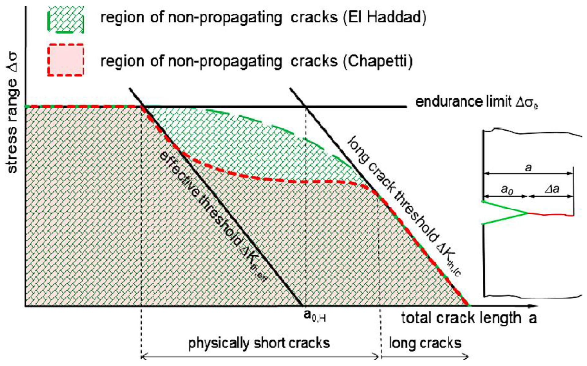
  • The corrosion pits are the preferred sites for crack initiation. The pit dimensions can affect the amount of threshold stress intensity factor (∆kth) below which fatigue cracks cannot propagate. Moreover, the exposure of the crack tip to the corrosive environment and hydrogen for a long time per cycle as well as time-dependent oxidation at elevated temperatures make the low frequency loading more harmful.
  • Microstructure is another factor influencing fatigue and corrosion fatigue behavior. For example, fatigue cracks in duplex stainless steel grow preferentially in the ferrite phase and are significantly affected by hydrogen embrittlement, whereas the ductile austenite phase delays the crack propagation. Furthermore, adding Al, Ti, Nb and Ta to increase the volume fraction of the phase γ″ and applying heat treatment improve the fatigue behavior of Ni-based superalloys.
  • Since fatigue and corrosion usually start from the surface damage, the surface state is of significant importance. Mechanical treatment of surfaces and/or application of a suitable coating are effective strategies to increase fatigue endurance limit.

Author Contributions

L.F.: Investigation, Methodology, Data curation, Formal analysis, Writing—review & editing, M.A.M.-B.: Investigation, Methodology, Writing—review & editing. All authors have read and agreed to the published version of the manuscript.

Funding

This research received no specific grant from any funding agency in the public, commercial, or not-for-profit sectors.

Institutional Review Board Statement

The study did not require ethical approval.

Data Availability Statement

Not applicable.

Acknowledgments

We would like to thank the Research Center of University of Bonab for the support of this study.

Conflicts of Interest

The author declares no conflict of interest.

References

  1. Kulor, F.; Markus, E.D.; Kanzumba, K. Design and control challenges of hybrid, dual nozzle gas turbine power generating plant: A critical review. Energy Rep. 2021, 7, 324–335. [Google Scholar] [CrossRef]
  2. Mangra, A.C. Design and Numerical Analysis of a Micro Gas Turbine Combustion Chamber. Eng. Technol. Appl. Sci. Res. 2020, 10, 6422–6426. [Google Scholar] [CrossRef]
  3. Wei, D.; Lei, L.; Yinghou, J.; Songtao, W.; Xingchen, L.; Sunden, B. Heat transfer in the trailing region of gas turbines—A state-of-the-art review. Appl. Therm. Eng. 2021, 199, 117614. [CrossRef]
  4. Ajiwibowo, M.W.; Darmawan, A.; Aziz, M. A conceptual chemical looping combustion power system design in a power-to-gas energy storage scenario. Int. J. Hydrogen Energy 2018, 44, 9636–9642. [Google Scholar] [CrossRef]
  5. Öberg, S.; Odenberger, M.; Johnsson, F. Exploring the competitiveness of hydrogen-fueled gas turbines in future energy systems. Int. J. Hydrogen Energy 2021, 47, 624–644. [Google Scholar] [CrossRef]
  6. Gupta, K.; Rehman, A.; Sarviya, R. Bio-fuels for the gas turbine: A review. Renew. Sustain. Energy Rev. 2010, 14, 2946–2955. [Google Scholar] [CrossRef]
  7. Sirignano, W.A.; Liu, F. Performance Increases for Gas-Turbine Engines Through Combustion Inside the Turbine. J. Propuls. Power 1999, 15, 111–118. [Google Scholar] [CrossRef]
  8. Poullikkas, A. An overview of current and future sustainable gas turbine technologies. Renew. Sustain. Energy Rev. 2005, 9, 409–443. [Google Scholar] [CrossRef]
  9. Shirzadi, A.; Jackson, S. Structural Alloys for Power Plants, Operational Challenges and High-Temperature Materials; Woodhead Publishing Series in Energy: Cambridge, UK, 2014; pp. 3–21. [Google Scholar]
  10. Cheddie, D.F. Thermo-economic optimization of an indirectly coupled solid oxide fuel cell/gas turbine hybrid power plant. Int. J. Hydrogen Energy 2011, 36, 1702–1709. [Google Scholar] [CrossRef]
  11. Park, Y.; Choi, M.; Kim, K.; Li, X.; Jung, C.; Na, S.; Choi, G. Prediction of operating characteristics for industrial gas turbine combustor using an optimized artificial neural network. Energy 2020, 213, 118769. [Google Scholar] [CrossRef]
  12. Salehnasab, B.; Poursaeidi, E.; Mortazavi, S.; Farokhian, G. Hot corrosion failure in the first stage nozzle of a gas turbine engine. Eng. Fail. Anal. 2016, 60, 316–325. [Google Scholar] [CrossRef]
  13. Bontempo, R.; Manna, M. Work and efficiency optimization of advanced gas turbine cycles. Energy Convers. Manag. 2019, 195, 1255–1279. [Google Scholar] [CrossRef]
  14. Shayegh, S.; Moreno-cruz, J.; Caldeira, K. Optimal gas turbine inlet temperature for cyclic operation. IOP Conf. Ser. J. Phys. Conf. Ser. 2018, 1111, 012046. [Google Scholar]
  15. Salim, B.; Orfi, J.; Alaqel, S.S. Effect of Turbine and Compressor Inlet Temperatures and Air Bleeding on the Comparative Performance of Simple and Combined Gas Turbine Unit. Eur. J. Eng. Technol. Res. 2020, 5, 39–45. [Google Scholar]
  16. Mirhosseini, A.M.; Nazari, S.A.; Pour, A.M.; Haghighi, S.E.; Zareh, M. Failure analysis of first stage nozzle in a heavy-duty gas turbine. Eng. Fail. Anal. 2019, 109, 104303. [Google Scholar] [CrossRef]
  17. Feuerstein, A.; Knapp, J.; Taylor, T.; Ashary, A.; Bolcavage, A.; Hitchman, N. Technical and Economical Aspects of Current Thermal Barrier Coating Systems for Gas Turbine Engines by Thermal Spray and EBPVD: A Review. J. Therm. Spray Technol. 2008, 17, 199–213. [Google Scholar] [CrossRef]
  18. Puspitasari, P.; Andoko, A.; Kurniawan, P. Failure analysis of a gas turbine blade: A review. IOP Conf. Ser. Mater. Sci. Eng. 2021, 1034, 012156. [Google Scholar] [CrossRef]
  19. Kanesund, J.; Brodin, H.; Johansson, S. Hot corrosion influence on deformation and damage mechanisms in turbine blades made of IN-792 during service. Eng. Fail. Anal. 2018, 96, 118–129. [Google Scholar] [CrossRef]
  20. Carter, T.J. Common failures in gas turbine blades. Eng. Fail. Anal. 2005, 12, 237–247. [Google Scholar] [CrossRef]
  21. Gurrappa, I.; Rao, A.S. Thermal barrier coatings for enhanced efficiency of gas turbine engines. Surf. Coat. Technol. 2006, 201, 3016–3029. [Google Scholar] [CrossRef]
  22. DeMasi-Marcin, J.T.; Gupta, D.K. Protective coatings in the gas turbine engine. Surf. Coat. Technol. 1994, 68, 1–9. [Google Scholar] [CrossRef]
  23. Salehnasab, B.; Poursaeidi, E. Mechanism and modeling of fatigue crack initiation and propagation in the directionally solidified CM186 LC blade of a gas turbine engine. Eng. Fract. Mech. 2020, 225, 106842. [Google Scholar] [CrossRef]
  24. Nowell, D.; Duó, P.; Stewart, I. Prediction of fatigue performance in gas turbine blades after foreign object damage. Int. J. Fatigue 2003, 25, 963–969. [Google Scholar] [CrossRef]
  25. Hou, J.; Wicks, B.J.; Antoniou, R.A. An investigation of fatigue failures of turbine blades in a gas turbine engine by mechanical analysis. Eng. Fail. Anal. 2002, 9, 201–211. [Google Scholar] [CrossRef]
  26. Li, K.-S.; Wang, J.; Fan, Z.-C.; Cheng, L.-Y.; Yao, S.-L.; Wang, R.-Z.; Zhang, X.-C.; Tu, S.-T. A life prediction method and damage assessment for creep-fatigue combined with high-low cyclic loading. Int. J. Fatigue 2022, 161, 106923. [Google Scholar] [CrossRef]
  27. Mazur, Z.; Ramirez, A.L.; Islas, J.A.J.; Amezcua, A.C. Failure analysis of a gas turbine blade made of Inconel 738LC alloy. Eng. Fail. Anal. 2005, 12, 474–486. [Google Scholar] [CrossRef]
  28. Shlyannikov, V.; Yarullin, R.; Zakharov, A. Fatigue of Steam Turbine Blades with Damage on the Leading Edge. Procedia Mater. Sci. 2014, 3, 1792–1797. [Google Scholar] [CrossRef] [Green Version]
  29. Gu, S.; An, D.; Qiu, G.; Wang, R.; Liu, Y. Failure Analysis of Compressor IGV in 9F Gas Turbine Generator Unit. J. Fail. Anal. Prev. 2022, 22, 1393–1399. [Google Scholar] [CrossRef]
  30. Katinić, M.; Kozak, D.; Gelo, I.; Damjanović, D. Corrosion fatigue failure of steam turbine moving blades: A case study. Eng. Fail. Anal. 2019, 106, 104136. [Google Scholar] [CrossRef]
  31. Liu, X.; Luo, Y.; Wang, Z. A review on fatigue damage mechanism in hydro turbines. Renew. Sustain. Energy Rev. 2016, 54, 1–14. [Google Scholar] [CrossRef]
  32. Rajabinezhad, M.; Bahrami, A.; Mousavinia, M.; Seyedi, S.J.; Taheri, P. Corrosion-Fatigue Failure of Gas-Turbine Blades in an Oil and Gas Production Plant. Materials 2020, 13, 900. [Google Scholar] [CrossRef] [Green Version]
  33. Plesiutschnig, E.; Fritzl, P.; Enzinger, N.; Sommitsch, C. Fracture analysis of a low pressure steam turbine blade. Case Stud. Eng. Fail. Anal. 2016, 5, 39–50. [Google Scholar] [CrossRef] [Green Version]
  34. Kanesund, J.; Brodin, H.; Johansson, S. High temperature corrosion influence on deformation and damage mechanisms in turbine blades made of IN-792 during service. Eng. Fail. Anal. 2020, 110, 104388. [Google Scholar] [CrossRef]
  35. Hata, S.; Nagai, N.; Yasui, T.; Tsukamoto, H. Investigation of Corrosion Fatigue Phenomena in Transient Zone and Preventive Coating and Blade Design against Fouling and Corrosive Environment for Mechanical Drive Turbines. Int. J. Fluid Mach. Syst. 2008, 1, 121–139. [Google Scholar] [CrossRef] [Green Version]
  36. Mukhopadhyay, N.; Chowdhury, S.; Das, G.; Chattoraj, I.; Das, S.; Bhattacharya, D. An investigation of the failure of low pressure steam turbine blades. Eng. Fail. Anal. 1998, 5, 181–193. [Google Scholar] [CrossRef]
  37. Sriraman, M.R.; Pidaparti, R.M. Crack Initiation Life of Materials Under Combined Pitting Corrosion and Cyclic Loading. J. Mater. Eng. Perform. 2009, 19, 7–12. [Google Scholar] [CrossRef]
  38. Rokhlin, S.I.; Kim, J.Y.; Nagy, H.; Zoofan, B. Effect of pitting corrosion on fatigue crack initiation and fatigue life. Eng. Fract. Mech. 1999, 43, 425–444. [Google Scholar] [CrossRef]
  39. Igwemezie, V.; Mehmanparast, A. Waveform and frequency effects on corrosion-fatigue crack growth behaviour in modern marine steels. Int. J. Fatigue 2020, 134, 105484. [Google Scholar] [CrossRef]
  40. Olugbade, T.O.; Ojo, O.T.; Omiyale, B.O.; Olutomilola, E.O.; Olorunfemi, B.J. A review on the corrosion fatigue strength of surface-modified stainless steels. J. Braz. Soc. Mech. Sci. Eng. 2021, 43, 421. [Google Scholar] [CrossRef]
  41. EL May, M.; Saintier, N.; Devos, O.; Rozinoer, A. Effect of Corrosion on the Low-cycle Fatigue Strength of Steels used in Frequent Start-up Power Generation Steam Turbine. Procedia Eng. 2015, 133, 528–534. [Google Scholar] [CrossRef] [Green Version]
  42. Rivaz, A.; Anijdan, S.M.; Moazami-Goudarzi, M. Failure analysis and damage causes of a steam turbine blade of 410 martensitic stainless steel after 165,000 h of working. Eng. Fail. Anal. 2020, 113, 104557. [Google Scholar] [CrossRef]
  43. Thellaputta, G.R.; Chandra, P.S.; Rao, C. Machinability of Nickel Based Superalloys: A Review. Mater. Today Proc. 2017, 4, 3712–3721. [Google Scholar] [CrossRef]
  44. Child, D.J.; Meldrum, J.; Onwuarolu, P. Corrosion-fatigue testing of Ni-based superalloy RR1000. Mater. Sci. Technol. 2016, 33, 1040–1047. [Google Scholar] [CrossRef]
  45. Masuyama, F. Low-alloyed steel grades for boilers in ultra-supercritical power plants. In Materials for Ultra-Supercritical and Advanced Ultra-Supercritical Power Plants; Elsevier: Amsterdam, The Netherlands, 2017; pp. 53–76. [Google Scholar]
  46. Kumari, S.; Satyanarayana, D.; Srinivas, M. Failure analysis of gas turbine rotor blades. Eng. Fail. Anal. 2014, 45, 234–244. [Google Scholar] [CrossRef]
  47. Rao, A.R.; Dutta, B. Vibration analysis for detecting failure of compressor blade. Eng. Fail. Anal. 2012, 25, 211–218. [Google Scholar]
  48. Kargarnejad, S.; Djavanroodi, F. Failure assessment of Nimonic 80A gas turbine blade. Eng. Fail. Anal. 2012, 26, 211–219. [Google Scholar] [CrossRef]
  49. Katinić, M.; Kozak, D. Steam turbine moving blade failure caused by corrosion fatigue–case history. Procedia Struct. Integr. 2018, 13, 2040–2047. [Google Scholar] [CrossRef]
  50. Kwon, H.; Lee, D.; Lee, Y. Failure analysis of blades and vanes of a compressor for a gas turbine engine. Eng. Fail. Anal. 2021, 124, 105386. [Google Scholar] [CrossRef]
  51. Brooking, L.; Gray, S.; Sumner, J.; Nicholls, J.; Simms, N. Interaction of hot corrosion fatigue and load dwell periods on a nickel-base single crystal superalloy. Int. J. Fatigue 2018, 117, 13–20. [Google Scholar] [CrossRef]
  52. Wang, R.; Zhang, B.; Hu, D.; Jiang, K.; Liu, H.; Mao, J.; Jing, F.; Hao, X. Thermomechanical fatigue experiment and failure analysis on a nickel-based superalloy turbine blade. Eng. Fail. Anal. 2019, 102, 35–45. [Google Scholar] [CrossRef]
  53. Lesiuk, J.F. Fatigue failure analysis of last stage blade in a low pressure steam turbine. Eng. Fail. Anal. 1998, 6, 93–100. [Google Scholar]
  54. Wei, Y.; Li, Y.; Lai, J.; Zhao, Q.; Yang, L.; Lin, Q.; Wang, X.; Pan, Z.; Lin, Z. Analysis on corrosion fatigue cracking mechanism of 17-4PH blade of low pressure rotor of steam turbine. Eng. Fail. Anal. 2020, 118, 104925. [Google Scholar] [CrossRef]
  55. Elmekawy, A.M.N.; Ali, M.E.H. Computational modeling of non-equilibrium condensing steam flows in low-pressure steam turbines. Results Eng. 2019, 5, 100065. [Google Scholar] [CrossRef]
  56. Jaffee, R.I. Titanium Steam Turbine Blading. In Proceedings of the Electric Power Research Institute (EPRI) Workshop on Titanium Steam Turbine Blading, Palo Alto, CA, USA, 9–10 November 1988; pp. 1–25. [Google Scholar]
  57. Perkins, K.; Bache, M. Corrosion fatigue of a 12%Cr low pressure turbine blade steel in simulated service environments. Int. J. Fatigue 2005, 27, 1499–1508. [Google Scholar] [CrossRef]
  58. Lourenço, N.; Graça, M.; Franco, L.; Silva, O. Fatigue failure of a compressor blade. Eng. Fail. Anal. 2008, 15, 1150–1154. [Google Scholar] [CrossRef]
  59. Schönbauer, B.M.; Stanzl-Tschegg, S.E.; Perlega, A.; Salzman, R.N.; Rieger, N.F.; Zhou, S.; Turnbull, A.; Gandy, D. Fatigue life estimation of pitted 12% Cr steam turbine blade steel in different environments and at different stress ratios. Int. J. Fatigue 2014, 65, 33–43. [Google Scholar] [CrossRef]
  60. Almaraz, G.M.D.; Tapia, M.G.; Zuñiga, I.F.; Almaraz, G.M.D.; Tapia, T.G.; Zuñiga, I.F. Ultrasonic fatigue endurance of Inconel 718 after the heat treatments: Solution annealing and double aging. Procedia Struct. Integr. 2022, 39, 281–289. [Google Scholar] [CrossRef]
  61. Mokaberi, A.; Derakhshandeh-Haghighi, R.; Abbaszadeh, Y. Fatigue fracture analysis of gas turbine compressor blades. Eng. Fail. Anal. 2015, 58, 1–7. [Google Scholar] [CrossRef]
  62. Ziegler, D.; Puccinelli, M.; Bergallo, B.; Picasso, A. Case Studies in Engineering Failure Analysis Investigation of turbine blade failure in a thermal power. Biochem. Pharmacol. 2013, 1, 192–199. [Google Scholar]
  63. Adnyana, D.N. Corrosion Fatigue of a Low-Pressure Steam Turbine Blade. J. Fail. Anal. Prev. 2018, 18, 162–173. [Google Scholar] [CrossRef]
  64. Adedipe, O.; Brennan, F.; Kolios, A. Review of corrosion fatigue in offshore structures: Present status and challenges in the offshore wind sector. Renew. Sustain. Energy Rev. 2016, 61, 141–154. [Google Scholar] [CrossRef]
  65. Pollock, T.M.; Tin, S. Nickel-based superalloys for advanced turbine engines: Chemistry, microstructure, and properties. J. Propuls. Power 2006, 22, 361–374. [Google Scholar] [CrossRef]
  66. Dawood, M.N.; Salim, A.M. A Review on Characterization, Classifications, and Applications of Super Alloys. J. Univ. Babylon Eng. Sci. 2021, 29, 53–62. [Google Scholar]
  67. Ebara, R. Corrosion fatigue phenomena learned from failure analysis. Eng. Fail. Anal. 2006, 13, 516–525. [Google Scholar] [CrossRef]
  68. Encinas-Oropesa, A.; Drew, G.; Hardy, M.; Leggett, A.; Nicholls, J.; Simms, N. Effects of Oxidation and Hot Corrosion in a Nickel Disc Alloy. In Proceedings of the Eleventh International Symposium on Superalloys, Champion, PA, USA, 14–18 September 2008. [Google Scholar]
  69. Zhao, G.; Qi, H.; Li, S.; Yang, X.; Shi, D. Effects of tensile load hold time on the fatigue and corrosion-fatigue behavior of turbine blade materials. Int. J. Fatigue 2021, 152, 106448. [Google Scholar] [CrossRef]
  70. Abedini, M.; Jahangiri, M.R.; Karimi, P. Oxidation and Hot Corrosion Behaviors of Service-Exposed and Heat-Treated Gas Turbine Vanes Made of IN939 Alloy. Oxid. Met. 2018, 90, 469–484. [Google Scholar] [CrossRef]
  71. Prashar, G.; Vasudev, H. Hot corrosion behavior of super alloys. Mater. Today Proc. 2020, 26, 1131–1135. [Google Scholar] [CrossRef]
  72. Montero, X.; Ishida, A.; Meißner, T.; Murakami, H.; Galetz, M. Effect of surface treatment and crystal orientation on hot corrosion of a Ni-based single-crystal superalloy. Corros. Sci. 2020, 166, 108472. [Google Scholar] [CrossRef]
  73. Hendery, M.; Whittaker, M.; Cockings, B.; Mignanelli, P. The effect of salt composition on the stress-free and corrosion-fatigue performance of a fine-grained nickel-based superalloy. Corros. Sci. 2022, 198, 110113. [Google Scholar] [CrossRef]
  74. Khajavi, M.; Shariat, M. Failure of first stage gas turbine blades. Eng. Fail. Anal. 2004, 11, 589–597. [Google Scholar] [CrossRef]
  75. Cockings, H.; Cockings, B.; Harrison, W.; Dowd, M.; Perkins, K.; Whittaker, M.; Gibson, G. The effect of near-surface plastic deformation on the hot corrosion and high temperature corrosion-fatigue response of a nickel-based superalloy. J. Alloys Compd. 2020, 832, 154889. [Google Scholar] [CrossRef]
  76. Zhang, X.; Gao, H.; Wen, Z.; Zhang, H.; Yue, Z. Low Cycle Fatigue Failure Analysis of a Ni-Based Single Crystal Superalloys at 850 °C. Adv. Eng. Mater. 2018, 21, 1800647. [Google Scholar] [CrossRef]
  77. Pippan, R. Dislocation emission and fatigue crack growth threshold. Acta Met. Mater. 1991, 39, 255–262. [Google Scholar] [CrossRef]
  78. Zhang, Y.; Shi, H.-J.; Gu, J.; Li, C.; Kadau, K.; Luesebrink, O. Crystallographic analysis for fatigue small crack growth behaviors of a nickel-based single crystal by in situ SEM observation. Theor. Appl. Fract. Mech. 2013, 69, 80–89. [Google Scholar] [CrossRef]
  79. Li, S.; Yang, X.; Qi, H.; Song, J.; Shi, D. Low-temperature hot corrosion effects on the low-cycle fatigue lifetime and cracking behaviors of a powder metallurgy Ni-based superalloy. Int. J. Fatigue 2018, 116, 334–343. [Google Scholar] [CrossRef]
  80. Cockings, H.L.; Perkins, K.M.; Dowd, M. Influence of environmental factors on the corrosion-fatigue response of a nickel-based superalloy. Mater. Sci. Technol. 2016, 33, 1048–1055. [Google Scholar] [CrossRef]
  81. Brooking, L.; Gray, S.; Sumner, J.; Nicholls, J.; Marchant, G.; Simms, N. Effect of stress state and simultaneous hot corrosion on the crack propagation and fatigue life of single crystal superalloy CMSX-4. Int. J. Fatigue 2018, 116, 106–117. [Google Scholar] [CrossRef]
  82. Sahu, J.; Kumar, B.R.; Das, S.; Paulose, N.; Mannan, S. Isothermal high temperature low cycle fatigue behavior of Nimonic-263: Influence of type I and type II hot corrosion. Mater. Sci. Eng. A 2014, 622, 131–138. [Google Scholar] [CrossRef]
  83. Mahobia, G.; Paulose, N.; Mannan, S.; Sudhakar, R.; Chattopadhyay, K.; Srinivas, N.S.; Singh, V. Effect of hot corrosion on low cycle fatigue behavior of superalloy IN718. Int. J. Fatigue 2014, 59, 272–281. [Google Scholar] [CrossRef]
  84. Gabb, T.P.; Telesman, J.; Hazel, B.; Mourer, D.P. The Effects of Hot Corrosion Pits on the Fatigue Resistance of a Disk Superalloy. J. Mater. Eng. Perform. 2009, 19, 77–89. [Google Scholar] [CrossRef] [Green Version]
  85. Mousavinia, M.; Bahrami, A.; Rafiaei, S.; Rajabinezhad, M.; Taghian, M.; Seyedi, S. Root cause analysis of failure of bolts in the low pressure section of a gas turbine in an oil and gas production plant. Eng. Fail. Anal. 2020, 115, 104675. [Google Scholar] [CrossRef]
  86. Qian, C.; Cui, H. Study on thermomechanical behavior and fatigue life prediction method of nickel base superalloy GH4169. In Proceedings of the AIAA Scitech 2019 Forum, San Diego, CA, USA, 7–11 January 2019. [Google Scholar]
  87. Nagabandi, K.; Pujari, A.K.; Iyer, D.S. Thermo-mechanical assessment of gas turbine combustor tile using locally varying thermal barrier coating thickness. Appl. Therm. Eng. 2020, 179, 115657. [Google Scholar] [CrossRef]
  88. Jacobsson, L.; Persson, C.; Melin, S. Thermo-mechanical fatigue crack propagation experiments in Inconel 718. Int. J. Fatigue 2009, 31, 1318–1326. [Google Scholar] [CrossRef]
  89. Jacobsson, L.; Persson, C.; Melin, S. Experimental methods for thermomechanical fatigue in gas turbine materials. In Proceedings of the 15th European Conference of Fracture, Stockholm, Sweden, 11–13 August 2004. [Google Scholar]
  90. Mishra, R.K.; Vaishakhi, N.; Bhatt, R.R. Thermo-mechanical Fatigue Failure of a Low-Pressure Turbine Blade in a Turbofan Engine. J. Fail. Anal. Prev. 2018, 18, 233–240. [Google Scholar] [CrossRef]
  91. Chen, Z.; Li, X.; Dong, T.; Pei, Y.; Gong, S.; Li, S. The mechanism of thermal corrosion fatigue (TCF) on nickel-based single crystal superalloy and the corresponding structure shape effect. Corros. Sci. 2020, 179, 109142. [Google Scholar] [CrossRef]
  92. Segersäll, M.; Leidermark, D.; Moverare, J.J. Influence of crystal orientation on the thermomechanical fatigue behaviour in a single-crystal superalloy. Mater. Sci. Eng. A 2015, 623, 68–77. [Google Scholar] [CrossRef] [Green Version]
  93. Pang, H.T.; Reed, P.A.S. Fatigue crack initiation and short crack growth in nickel-base turbine disc alloys—The effects of microstructure and operating parameters. Int. J. Fatigue 2003, 25, 1089–1099. [Google Scholar] [CrossRef]
  94. Tan, Y.; Bull, D.; Jiang, R.; Evangelou, A.; Chaudhuri, S.; Octaviani, S.; Pierron, F.; Gao, N.; Toda, H.; Sinclair, I.; et al. Data rich imaging approaches assessing fatigue crack initiation and early propagation in a DS superalloy at room temperature. Mater. Sci. Eng. A 2020, 805, 140592. [Google Scholar] [CrossRef]
  95. El May, M.; Saintier, N.; Palin-Luc, T.; Devos, O.; Brucelle, O. Modelling of corrosion fatigue crack initiation on martensitic stainless steel in high cycle fatigue regime. Corros. Sci. 2018, 133, 397–405. [Google Scholar] [CrossRef]
  96. El May, M.; Palin-Luc, T.; Saintier, N.; Devos, O. Effect of corrosion on the high cycle fatigue strength of martensitic stainless steel X12CrNiMoV12-3. Int. J. Fatigue 2013, 47, 330–339. [Google Scholar] [CrossRef] [Green Version]
  97. Kovacs, S.; Beck, T.; Singheiser, L. Influence of mean stresses on fatigue life and damage of a turbine blade steel in the VHCF-regime. Int. J. Fatigue 2013, 49, 90–99. [Google Scholar] [CrossRef]
  98. Zhao, W.; Wang, Y.; Zhang, T.; Wang, Y. Study on the mechanism of high-cycle corrosion fatigue crack initiation in X80 steel. Corros. Sci. 2012, 57, 99–103. [Google Scholar] [CrossRef]
  99. El May, M.; Saintier, N.; Palin-Luc, T.; Devos, O. Non-local high cycle fatigue strength criterion for metallic materials with corrosion defects. Fatigue Fract. Eng. Mater. Struct. 2015, 38, 1017–1025. [Google Scholar] [CrossRef] [Green Version]
  100. Co, N.E.C.; Burns, J.T. Effects of macro-scale corrosion damage feature on fatigue crack initiation and fatigue behavior. Int. J. Fatigue 2017, 103, 234–247. [Google Scholar] [CrossRef]
  101. Ebara, R. Corrosion fatigue crack initiation in 12% chromium stainless steel. Mater. Sci. Eng. A 2007, 468, 109–113. [Google Scholar] [CrossRef]
  102. Zhang, Y.; Liu, X.; Lai, J.; Wei, Y.; Luo, J. Corrosion fatigue life prediction of crude oil storage tank via improved equivalent initial flaw size. Theor. Appl. Fract. Mech. 2021, 114, 103023. [Google Scholar] [CrossRef]
  103. Larrosa, N.O.; Akid, R.; Ainsworth, R.A. Corrosion-fatigue: A review of damage tolerance models. Int. Mater. Rev. 2017, 63, 283–308. [Google Scholar] [CrossRef] [Green Version]
  104. Li, S.-X.; Akid, R. Corrosion fatigue life prediction of a steel shaft material in seawater. Eng. Fail. Anal. 2013, 34, 324–334. [Google Scholar] [CrossRef]
  105. Yang, Z.; Lie, S.; Gho, W. Fatigue crack growth analysis of a square hollow section T-joint. J. Constr. Steel Res. 2006, 63, 1184–1193. [Google Scholar] [CrossRef]
  106. Poursaeidi, E.; Bakhtiari, H. Fatigue crack growth simulation in a first stage of compressor blade. Eng. Fail. Anal. 2014, 45, 314–325. [Google Scholar] [CrossRef]
  107. Döker, H. Fatigue crack growth threshold: Implications, determination and data evaluation. Int. J. Fatigue 1997, 19, 145–149. [Google Scholar] [CrossRef]
  108. Bang, D.; Ince, A. A short and long crack growth model based on 2-parameter driving force and crack growth thresholds. Int. J. Fatigue 2020, 141, 105870. [Google Scholar] [CrossRef]
  109. Padula, S.A., II; Shyam, A.; Ritchie, R.O.; Milligan, W.W. High frequency fatigue crack propagation behavior of a nickel-base turbine disk alloy. Int. J. Fatigue 1999, 21, 725–731. [Google Scholar] [CrossRef]
  110. Xiaojing, C.; Ri, X.; Mingchen, H.; Jinquan, X. A threshold formula for fatigue crack growth with mean stress intensity factors. Int. J. Mech. Sci. 2018, 135, 639–645. [Google Scholar]
  111. Maierhofer, J.; Pippan, R.; Gänser, H.-P. Modified NASGRO equation for physically short cracks. Int. J. Fatigue 2014, 59, 200–207. [Google Scholar] [CrossRef] [Green Version]
  112. Barlow, K.; Chandra, R. Fatigue crack propagation simulation in an aircraft engine fan blade attachment. Int. J. Fatigue 2005, 27, 1661–1668. [Google Scholar] [CrossRef]
  113. Semenov, A.; Semenov, S.; Nazarenko, A.; Getsov, L. Computer simulation of fatigue, creep and thermal-fatigue cracks properties in gas-turbine blades. Mater. Tehnol./Mater. Technol. 2012, 46, 197–203. [Google Scholar]
  114. Li, Z.; Li, S.; Xu, G.; Shi, D.; Liu, C.; Yang, X. The framework of hot corrosion fatigue life estimation of a PM superalloy using notch fatigue methodology combined with pit evaluation. Int. J. Fatigue 2021, 153, 106483. [Google Scholar] [CrossRef]
  115. Maierhofer, J.; Gänser, H.P.; Pippan, R. Modified Kitagawa-Takahashi diagram accounting for finite notch depths. Int. J. Fatigue 2015, 70, 503–509. [Google Scholar] [CrossRef] [Green Version]
  116. Peters, J.; Boyce, B.; Chen, X.; McNaney, J.; Hutchinson, J.; Ritchie, R. On the application of the Kitagawa–Takahashi diagram to foreign-object damage and high-cycle fatigue. Eng. Fract. Mech. 2002, 69, 1425–1446. [Google Scholar] [CrossRef]
  117. Chan, K.S.; Enright, M.P.; Moody, J.P. Development of a Probabilistic Methodology for Predicting Hot Corrosion Fatigue Crack Growth Life of Gas Turbine Engine Disks. J. Eng. Gas Turbines Power 2013, 136, 022505. [Google Scholar] [CrossRef]
  118. Jirandehi, A.P.; Chakherlou, T. A fatigue crack initiation and growth life estimation method in single-bolted connections. J. Strain Anal. Eng. Des. 2019, 54, 79–94. [Google Scholar] [CrossRef]
  119. Rungta, R.; Begley, J.A.; Staehle, R.W. Effect of Steam Impurities on Corrosion Fatigue Crack Growth Rates of a Turbine Disc Steel. Corrosion 1981, 37, 682–690. [Google Scholar] [CrossRef]
  120. Schönbauer, B.M.; Stanzl-Tschegg, S.E.; Perlega, A.; Salzman, R.N.; Rieger, N.F.; Turnbull, A.; Zhou, S.; Lukaszewicz, M.; Gandy, D. The influence of corrosion pits on the fatigue life of 17-4PH steam turbine blade steel. Eng. Fract. Mech. 2015, 147, 158–175. [Google Scholar] [CrossRef]
  121. Zhou, S.; Turnbull, A. Influence of pitting on the fatigue life of a turbine blade steel. Fatigue Fract. Eng. Mater. Struct. 1999, 22, 1083–1093. [Google Scholar] [CrossRef]
  122. Sadananda, K.; Vasudevan, A. Analysis of pit to crack transition under corrosion fatigue & the safe-life approach using the modified Kitagawa-Takahashi diagram. Int. J. Fatigue 2020, 134, 105471. [Google Scholar]
  123. Cerit, M.; Genel, K.; Eksi, S. Numerical investigation on stress concentration of corrosion pit. Eng. Fail. Anal. 2009, 16, 2467–2472. [Google Scholar] [CrossRef]
  124. Shipilov, S.A. Mechanisms for corrosion fatigue crack propagation. J. Chin. Soc. Corros. Prot. 2004, 24, 321–333. [Google Scholar] [CrossRef]
  125. De Seranno, T.; Lambrechts, E.; Verliefde, A.; Depover, T.; Verbeken, K. Mechanistic interpretation on acidic stress-corrosion cracking of NiCrMoV steam turbine steel. Mater. Sci. Eng. A 2020, 802, 140433. [Google Scholar] [CrossRef]
  126. Michailidis, N.; Stergioudi, F.; Maliaris, G.; Tsouknidas, A. Influence of galvanization on the corrosion fatigue performance of high-strength steel. Surf. Coat. Technol. 2014, 259, 456–464. [Google Scholar] [CrossRef]
  127. Suresh, S.; Ritchie, R.O. Mechanistic dissimilarities between environmentally influenced fatigue-crack propagation at near-threshold and higher growth rates in lower strength steels. Met. Sci. 1982, 16, 529–538. [Google Scholar] [CrossRef] [Green Version]
  128. Maktouf, W.; Saï, K. An investigation of premature fatigue failures of gas turbine blade. Eng. Fail. Anal. 2015, 47, 89–101. [Google Scholar] [CrossRef]
  129. Luer, K.; DuPont, J.; Marder, A.; Skelonis, C. Materials at High Temperatures Corrosion fatigue of alloy 625 weld claddings in combustion environments Corrosion fatigue of alloy 625 weld claddings in combustion environments. Mater. High Temp. 2001, 18, 11–19. [Google Scholar] [CrossRef]
  130. Chen, T.; Nutter, J.; Hawk, J.; Liu, X. Corrosion fatigue crack growth behavior of oil-grade nickel-base alloy 718. Part 1: Effect of corrosive environment. Corros. Sci. 2014, 89, 146–153. [Google Scholar] [CrossRef]
  131. Barsom, J. Corrosion-fatigue crack propagation below KIscc. Eng. Fract. Mech. 1971, 3, 15–25. [Google Scholar] [CrossRef]
  132. Ghonem, H.; Wen, Y.; Zheng, D.; Thompson, M.; Linsey, G. Effects of temperature and frequency on fatigue crack growth in Ti-β21S monolithic laminate. Mater. Sci. Eng. A 1993, 161, 45–53. [Google Scholar] [CrossRef]
  133. Pradhan, A.; Vishwakarma, M.; Dwivedi, S.K. A review: The impact of hydrogen embrittlement on the fatigue strength of high strength steel. Mater. Today Proc. 2020, 26, 3015–3019. [Google Scholar] [CrossRef]
  134. Cunningham, B.M.D.; Evangelou, A.; You, C.; Morris, A.; Wise, J.; Reed, P.A.S.; Hamilton, A.R. Fatigue crack initiation and growth behavior in a notch with periodic overloads in the low-cycle fatigue regime of FV566 ex-service steam turbine blade material. Fatigue Fract. Eng. Mater. Struct. 2021, 45, 546–564. [Google Scholar] [CrossRef]
  135. Ebara, R. The influence of metallurgical factors on corrosion fatigue strength of stainless steels. Procedia Struct. Integr. 2016, 2, 517–524. [Google Scholar] [CrossRef] [Green Version]
  136. Makhlouf, K.; Sidhom, H.; Triguia, I.; Braham, C. Corrosion fatigue crack propagation of a duplex stainless steel X6 Cr Ni Mo Cu 25-6 in air and in artificial sea water. Int. J. Fatigue 2003, 25, 167–179. [Google Scholar] [CrossRef]
  137. Marrow, T.J.; King, J.E. Microstructural and environmental effects on fatigue crack propagation in duplex stainless steels. Fatigue Fract. Eng. Mater. Struct. 1994, 17, 761–771. [Google Scholar] [CrossRef]
  138. Pradhan, K.K.; Matawale, C.R. Heat treatment analysis of SS304 for gas turbine application. Mater. Today Proc. 2020, 33, 5734–5739. [Google Scholar] [CrossRef]
  139. Akita, M.; Uematsu, Y.; Kakiuchi, T.; Nakajima, M.; Tsuchiyama, T.; Bai, Y.; Isono, K. Effect of sensitization on corrosion fatigue behavior of type 304 stainless steel annealed in nitrogen gas. Mater. Sci. Eng. A 2015, 640, 33–41. [Google Scholar] [CrossRef]
  140. Sui, S.; Zhong, C.; Chen, J.; Gasser, A.; Huang, W.; Schleifenbaum, J.H. Influence of solution heat treatment on microstructure and tensile properties of Inconel 718 formed by high-deposition-rate laser metal deposition. J. Alloys Compd. 2018, 740, 389–399. [Google Scholar] [CrossRef]
  141. Li, W.J.; Liu, Y.; Wang, Y.; Han, C.; Tang, H.P. Hot corrosion behavior of Ni-16Cr-xAl based alloys in mixture of Na 2SO 4-NaCl at 600 °C. Trans. Nonferrous Met. Soc. China 2011, 21, 2617–2625. [Google Scholar] [CrossRef]
  142. Li, X.; Zhang, J.; Fu, Q.; Akiyama, E.; Song, X.; Shen, S.; Li, Q. Hydrogen embrittlement of high strength steam turbine last stage blade steels: Comparison between PH17-4 steel and PH13-8Mo steel. Mater. Sci. Eng. A 2018, 742, 353–363. [Google Scholar] [CrossRef]
  143. Balitskii, A.I.; Kvasnytska, Y.H.; Ivaskevych, L.M.; Kvasnytska, K.H.; Balitskii, O.A. Hydrogen and Corrosion Resistance of Nickel Superalloys for Gas Turbines, Engines Cooled Blades. Energies 2023, 16, 1154. [Google Scholar] [CrossRef]
  144. Wee, S.; Do, J.; Kim, K.; Lee, C.; Seok, C.; Choi, B.-G.; Choi, Y.; Kim, W. Review on Mechanical Thermal Properties of Superalloys and Thermal Barrier Coating Used in Gas Turbines. Appl. Sci. 2020, 10, 5476. [Google Scholar] [CrossRef]
  145. Pourazizi, R.; Mohtadi-Bonab, M.; Szpunar, J. Role of texture and inclusions on the failure of an API X70 pipeline steel at different service environments. Mater. Charact. 2020, 164, 110330. [Google Scholar] [CrossRef]
  146. Mohtadi-Bonab, M.; Mousavi, H.; Pourazizi, R.; Szpunar, J. Finite element modeling of HIC propagation in pipeline steel with regard to experimental observations. Int. J. Hydrogen Energy 2020, 45, 23122–23133. [Google Scholar] [CrossRef]
  147. Morita, A.; Kagawa, H.; Sugawara, M.; Kondo, Y.; Kubo, S. Evaluation of corrosion fatigue crack propagation life at low-pressure steam turbine rotor groove. Eng. Fract. Mech. 2006, 73, 1615–1628. [Google Scholar] [CrossRef]
  148. Gibson, G.J.; Perkins, K.M.; Gray, S.; Leggett, A.J. Influence of shot peening on high-temperature corrosion and corrosion-fatigue of nickel based superalloy 720 Li. Mater. High Temp. 2016, 33, 225–233. [Google Scholar] [CrossRef] [Green Version]
  149. Preve´y, P.S.; Jayaraman, N.; Ravindranath, R. Fatigue Life Extension of Steam Turbine Alloys Using Low Plasticity Burnishing (LPB). In Proceedings of the ASME Turbo Expo 2010: Power for Land, Sea, and Air, Glasgow, UK, 14–18 June 2010; Volume 7, pp. 2277–2287. [Google Scholar]
  150. Preve, P.S. Case Studies of Fatigue Life Improvement Using Low Plasticity Burnishing in Gas Turbine Engine. J. Eng. Gas Turbine Power 2006, 128, 865–872. [Google Scholar] [CrossRef] [Green Version]
  151. Preve, P.S. The influence of surface enhancement by low plasticity burnishing on the corrosion fatigue performance of AA7075-T6. Int. J. Fatigue 2004, 26, 975–982. [Google Scholar] [CrossRef]
  152. Wang, C.; Luo, K.; Bu, X.; Su, Y.; Cai, J.; Zhang, Q.; Lu, J. Laser shock peening-induced surface gradient stress distribution and extension mechanism in corrosion fatigue life of AISI 420 stainless steel. Corros. Sci. 2020, 177, 109027. [Google Scholar] [CrossRef]
  153. Yan, X.; Yin, S.; Chen, C.; Jenkins, R.; Lupoi, R.; Bolot, R.; Ma, W.; Kuang, M.; Liao, H.; Lu, J.; et al. Fatigue strength improvement of selective laser melted Ti6Al4V using ultrasonic surface mechanical attrition. Mater. Res. Lett. 2019, 7, 327–333. [Google Scholar] [CrossRef]
  154. Peters, B.M.; Leyens, C.; Schulz, U.; Kaysser, W.A. EB-PVD Thermal Barrier Coatings for Aeroengines and Gas Turbines. Adv. Eng. Mater. 2001, 3, 193–204. [Google Scholar] [CrossRef]
  155. Shin, I.-H.; Koo, J.-M.; Seok, C.-S.; Yang, S.-H.; Lee, T.-W.; Kim, B.-S. Estimation of spallation life of thermal barrier coating of gas turbine blade by thermal fatigue test. Surf. Coat. Technol. 2011, 205, S157–S160. [Google Scholar] [CrossRef]
  156. Xu, H.; Guo, H.; Liu, F.; Gong, S. Development of gradient thermal barrier coatings and their hot-fatigue behavior. Surf. Coat. Technol. 2000, 130, 133–139. [Google Scholar] [CrossRef]
  157. Smialek, J.L.; Nesbitt, J.A.; Gabb, T.P.; Garg, A.; Miller, R.A. Hot corrosion and low cycle fatigue of a Cr2AlC-coated superalloy. Mater. Sci. Eng. A 2018, 711, 119–129. [Google Scholar] [CrossRef]
  158. Igwemezie, V.; Mehmanparast, A.; Kolios, A. Materials selection for XL wind turbine support structures: A corrosion-fatigue perspective. Mar. Struct. 2018, 61, 381–397. [Google Scholar] [CrossRef]
Figure 1. Schematic of gas turbine [12].
Metals 13 00701 g001
Figure 2. SEM images of (a) an area near the crack initiation, (b) the fracture surface [61].
Metals 13 00701 g002
Figure 3. A model for the initiation and growth of fatigue crack for salted IN718 at 650 °C [83].
Metals 13 00701 g003
Figure 4. Fracture face of the single-crystal superalloy CMSX-4 exposed to trapezoidal loading and temprature of 550 °C [51].
Metals 13 00701 g004
Figure 5. (a) A series of broken blades in a row, (b) stereomicroscope and (c,d) SEM image of the fracture surface affected by fatigue and corrosion, respectively [85].
Metals 13 00701 g005
Figure 6. SEM photos of TMF crack surface: (a) TMF crack surface with oxidation layer (blue arrows), (b) intergranular fracture feature (green arrows), (c) intergranular cracks (red arrows) [52].
Metals 13 00701 g006
Figure 7. A schematic representation of corrosion fatigue crack initiation in the X12CrNiMo12-3 martensitic stainless steel under cyclic loading [95].
Metals 13 00701 g007
Figure 8. The corrosion fatigue stages [102].
Metals 13 00701 g008
Figure 9. Paris law for crack growth, d a d N , as function of the stress intensity factor [105].
Metals 13 00701 g009
Figure 10. Kitagawa–Takahashi diagram according to El Haddad and Chapetti approaches. Here, Δ K t h , l c   denotes the threshold stress intensity factor for long cracks, and Δ K e f f is effective threshold stress intensity factor related to a 0 , H [115].
Metals 13 00701 g010
Figure 11. Stress concentration factor as a function of pit aspect ratio [122].
Metals 13 00701 g011
Figure 12. Effect of (a) oxygen content and (b) Cl on the corrosion fatigue life of FV566 in deionized water at 120 °C [57].
Metals 13 00701 g012
Figure 13. S–N curves of RR1000 superalloy coated with 55%K2SO4–45%KCl and 98%Na2SO4–2%NaCl and tested at 600 °C with an R ratio of −1 [73].
Metals 13 00701 g013
Figure 14. Potentiodynamic polarization curves of Ni alloy 718 tested in different corrosive conditions [130].
Metals 13 00701 g014
Figure 15. S–N curves of bare and salt-coated superalloy DZ125 under dynamic loading for hold times of (a) 1 s and (b) 240 s, (c) waveform loading schematic [69].
Metals 13 00701 g015
Figure 16. Effect of gap conditions on (a) crack initiation life, (b) crack propagation life; and (c) is a cross-section of the rotor groove determining the location of gaps [147].
Metals 13 00701 g016
Figure 17. The averaged fatigue data of superalloy RR1000 treated with 110H and 330H shot size [75].
Metals 13 00701 g017
Figure 18. (a) Fractured surface morphology of SMATed sample, (b) S–N curves of the as-fabricated (AF), hot isostatic pressing (HIP) and SMATed samples [153].
Metals 13 00701 g018
Figure 19. Bonding strength of the MCrAlY/YSZ coating on the Ni-base superalloy GTD111DS under thermal fatigue [155].
Metals 13 00701 g019
Table 1. Failure analysis summary of gas turbine components.
Material TypeWorking ConditionsType of DamageConsequencesRef
Ni-based superalloyHigh temperature, high pressureCorrosion fatigue,
oxidation
Corrosion pits, formation of carbide along grain boundaries, ϒ’-particle coarsening[46]
It is not mentionedFrequency of 500 HzFatigue,
oxidation
Fracture of blade at root of the airfoil due to high cycle fatigue, corrosion pitting on the leading edge of the blade[47]
Nimonic 80A superalloyFirst-stage blade of a 3 MW combustion turbine with a gas inlet temperature of 770 °CCreep failure,
oxidation
ϒ’-particle coarsening,
delamination of the coating and cracks at the interface of the bond coat and the base metal in the blade airfoil hot zones
[48]
Nimonic 105 superalloyWorking in hot and humid climate in Persian Gulf regionHot corrosion, thermal fatiguePitting corrosion on the surface of blade airfoil, intergranular cracks and fracture surface at the failure area on the trailing edge.[12]
Stainless steel90 °C, low pressureCorrosion fatigueDecrease in the fatigue strength under corrosion[41]
SteelWorking at phase transition zone of the turbineCorrosion fatigueFailure of steam turbine rotor blades[49]
Ti-6Al-4 V alloyRotor bladePitting corrosion, fatigue crackingFailure of rotor blade[50]
Single-crystal superalloy CMSX-4High temperature, in the presence of corrosive salt speciesHot corrosion fatigueCorrosion embrittlement, crack-tip oxidation[51]
Ni-based superalloy IN792Operating with 30 starts and stops in an industrial environmentCreep, hot corrosion, thermal mechanical fatiguePrecipitation of TiN and AlN near the crack due to corrosion/nitridation, formation of a ϒ’ depletion zone in front of crack, failure after 21,000 h[34]
Ni-based superalloy K444High temperature, low pressureThermomechanical fatigue, oxidationInitiation of crack at the trailing edge of blade[52]
Disclaimer/Publisher’s Note: The statements, opinions and data contained in all publications are solely those of the individual author(s) and contributor(s) and not of MDPI and/or the editor(s). MDPI and/or the editor(s) disclaim responsibility for any injury to people or property resulting from any ideas, methods, instructions or products referred to in the content.

