Article

Fracture Kinetics and Mechanisms of Ultrafine-Grained Materials during Fatigue Tests in the Low-Cycle Fatigue Region

by
Gennadiy V. Klevtsov
1,*,
Ruslan Z. Valiev
2,3,*,
Natal’ya A. Klevtsova
1,
Maksim N. Tyurkov
1,
Irina N. Pigaleva
1 and
Denis A. Aksenov
2,4
1
Department of Nanotechnology, Materials Science and Mechanics, Togliatti State University, 14 Belorusskaya St., 445020 Togliatti, Russia
2
Institute of Physics of Advanced Materials, Ufa University of Science and Technology, 32 Z. Validi St., 450076 Ufa, Russia
3
Laboratory for Dynamics and Extreme Performance of Advanced Nanostructured Materials, Saint Petersburg State University, 7-9 Universitetskaya nab., 199034 St. Petersburg, Russia
4
Institute of Molecule and Crystal Physics, Ufa Federal Research Center, Russian Academy of Sciences, 151 pr. Oktyabrya, 450075 Ufa, Russia
*
Authors to whom correspondence should be addressed.
Metals 2023, 13(4), 709; https://doi.org/10.3390/met13040709
Submission received: 28 February 2023 / Revised: 23 March 2023 / Accepted: 30 March 2023 / Published: 4 April 2023
(This article belongs to the Special Issue Multi-Axial Fatigue and Fracture Behavior in Metals)

Abstract

:
In this paper, the fracture kinetics and mechanisms in the low-cycle fatigue region were analyzed for different ultrafine-grained (UFG) materials with body-centered cubic (bcc), hexagonal close-packed (hcp) and face-centered cubic (fcc) lattices. Three-point bending principle fatigue tests were performed. The tests show that the UFG structure formation in the investigated materials has an ambiguous effect on the total number of cycles to failure (life) of the samples. The number of cycles to fatigue crack initiation (Nin) is about 20% of the total life of the samples, irrespective of the material state and the crystal lattice type. At the same value of the stress intensity coefficient range (∆K), for the majority of the investigated UFG materials, the fatigue crack propagation rate (dl/dN) is close to or lower than that of the initial coarse-grained (CG) materials. For the UFG materials, the coefficient n in the Paris equation is, in most cases, lower than that for the CG materials, which indicates that the UFG materials are less sensitive to cyclic overload. The fatigue fracture mechanisms of the investigated CG and UFG materials are rather similar, although the fracture of the UFG materials is accompanied by the formation of many secondary cracks, irrespective of the crystal lattice type.

1. Introduction

In the diagnostics of the sudden failure of products, fatigue fracture holds a special place, since up to 90% of all fractures in the aeronautical and automotive branches of engineering—and others, including the manufacturing of products for medical applications—are fatigue fractures [1,2,3]. Often, a fatigue crack forming at the initial stage of fracture is a stress raiser, subsequently initiating the brittle fracture of materials. As a rule, the fatigue fracture of technical systems is related to low-cycle fatigue [1,2,3,4]. Of special interest is the analysis of the fatigue fracture of products made of a new class of nanostructured material with an ultrafine-grained (UFG) structure, produced using severe plastic deformation (SPD) techniques [5]. The present-day notion of the fatigue of UFG materials is based on the fact that during the SPD processing of steels, titanium, Ti and Al alloys, Cu alloys and some other materials [3,6,7,8,9,10,11,12,13,14], the fatigue limit increases but fatigue strength in the low-cycle fatigue region declines or marginally increases. The low strength of UFG materials in the low-cycle fatigue region is attributed by several authors [7,13] to the lower tortuosity of a propagating crack or relatively well-developed cyclic plastic deformation at the crack tip [14].
To analyze the fracture kinetics of materials in the low-cycle fatigue region at the stage of crack propagation, at present, a kinetic diagram of fatigue fracture is used. It represents the dependence of the fatigue crack propagation rate (dl/dN) on the stress intensity coefficients ΔK or Kmax [15]. The straight-line portion of the kinetic diagram of fatigue fracture is described by the known Paris equation [16], dl/dN = C × ΔK(Kmax)n, where the coefficients C and n characterize the ability of a material to resist fatigue fracture. Estrin and Vinogradov [7,13] show that UFG metallic materials normally have lower threshold values of the ΔK coefficients and a higher crack propagation rate in steady-state conditions than coarse-grained (CG) materials at the same values of the ΔK coefficients. However, still unsolved is the issue of the facture behavior and mechanisms of UFG materials in the low-cycle fatigue region. Solving this issue is the aim of the present work, which involves a precise analysis of the fatigue fracture kinetics and mechanisms of various commercial alloys and steels with body-centered cubic (bcc), hexagonal close-packed (hcp) and face-centered cubic (fcc) lattices in the UFG and CG states.

2. Materials and Methods

As materials in the CG and UFG states, we used known commercial materials (steels and alloys) that have bcc lattices: certified C45 carbon steel, 9MnSi5 low-alloyed pipe steel, 12Cr-2W-2Ni-0.5Mo ferritic–martensitic steel (Table 1); hcp lattices: Grade 4 Ti, Ti-6Al-4V titanium alloy, a Mg6Al magnesium alloy (Table 2); fcc lattices: Fe-0.02C-18Cr-8Ni corrosion-resistant austenitic steel (Table 1), and an ENAW-2024 aluminum alloy (Table 3). The chemical composition of the 9MnSi5, 12Cr-2W-2Ni-0.5Mo and Fe-0.02C-18Cr-8Ni steels, as well as of the Ti-6Al-4V and ENAW-2024 alloys, was determined using a Q4 Tasman optical emission spectrometer (Bruker Elemental GmbH, Karlsruhe, Germany). The chemical composition of the Mg6Al magnesium alloy was determined using a Thermo Scientific ARL Optim’X X-ray fluorescence spectrometer (Thermo Fisher Scientific, Ecublens, Switzerland). Comprehensive studies in which the authors produced ultrafine-grained states in these materials via SPD were performed in recent years at the Institute of Physics of Advanced Materials, Ufa State Aviation Technical University (currently Ufa University of Science and Technology, Ufa, Russia) (see [5,17]). The specific details of this process are given below.
The C45 steel in the CG state was investigated after quenching and high tempering (550 °C). The UFG structure was produced using equal-channel angular pressing (ECAP) via the following regime: water quenching from a temperature of 800 °C and ECAP at 350 °C (route Bc, n = 6, φ = 120°) [5]. The 9MnSi5 steel was studied in the initial hot-rolled CG state and in the UFG state produced using ECAP. The UFG state was produced via the following regime: homogenizing annealing at 820 °C followed by water quenching and tempering at 350 °C, ECAP at 300 °C, and 4 passes via route Bc and additional annealing at 350 °C with a holding time of 10 min. The CG state of the 12Cr-2W-2Ni-0.5Mo steel was produced by heating it in a hot-rolled state to a temperature of 1050 °C for 1 h, followed by oil quenching and tempering at a temperature of 800 °C for 1 h. To produce a UFG state, the steel, after the above-mentioned heat treatment, was processed via ECAP at a temperature of 550 °C (route Bc, n = 4, φ = 120°). Then, the samples were subjected to additional annealing at a temperature of 850 °C for 1 h plus oil quenching [18].
Grade 4 Ti in the CG state was investigated after the homogenizing annealing of the hot-rolled billets at a temperature of 680 °C for 1 h. The UFG state of Ti was produced through treatment via the following regime: the homogenizing annealing of the billet at 680 °C for 1 h plus ECAP at a temperature of 250 °C (route Bc, n = 6) and annealing at 600 °C (1 h). The Ti-6Al-4V titanium alloy was studied in the initial CG state, as well as in the UFG state. The alloy’s initial state was produced via hot rolling of the billets. To produce a UFG state, the billet was subjected to homogenizing annealing at 960 °C followed by water quenching and tempering at 675 °C for 4 h and ECAP at 650 °C (route Bc, φ = 120°, n = 6). The Mg6Al magnesium alloy was studied in the initial state and in the ECAP-processed state. The initial state was produced via the homogenizing annealing of the as-cast alloy at a temperature of 430 °C for 24 h in argon medium. After the above-mentioned heat treatment, the Mg6Al alloy was subjected to ECAP at a temperature of 400 °C (n = 4, route Bc, φ = 120°) with intermediate annealing at the same temperature for 15 min.
The Fe-0.02C-18Cr-8Ni austenitic steel was investigated in the initial (hot-rolled) CG state and in the UFG state after ECAP processing. The UFG state was produced after the following treatment: quenching from a temperature of 1050 °C with preliminary holding for 1 h plus ECAP at a temperature of 350 °C (route Bc, n = 4, φ = 120°). The ENAW-2024 aluminum alloy was studied after the standard T6 treatment as follows: heating to a temperature of 530 °C, holding at this temperature for 1 h, and water quenching and aging at a temperature of 190 °C for 7 h with water cooling. The UFG state of the ENAW-2024 alloy was produced after ECAP processing at a temperature of 160 °C (route Bc, n = 6, φ = 90°).
A structural study of the materials with mean grain size evaluation was performed via scanning (JSM-6490LV, JEOL Ltd., Tokyo, Japan) and transmission electron microscopies (JEM-2100, JEOL Ltd., Tokyo, Japan). Hardness tests of the materials were conducted using a TH 300 hardness tester (TIME Group, Beijing, China). The static tension of the cylindrical samples with a diameter of 3 mm was carried out using an H50kT universal testing machine (Tinius Olsen, Redhill, UK) at a temperature of 20 °C, in accordance with GOST 1497-84. Fatigue tests were carried out on prismatic samples 10 mm thick, 15 mm tall and 85 mm in length, with a V-shaped stress raiser and 0.25 mm radius at the vertex. Fatigue tests were performed at a temperature of 20 °C using the three-point bending principle (Figure 1) using an Instron 8802 system at a loading frequency of ⱱ = 10 Hz, a stress ratio of R = 0.1 and several values of the cycle stress range ΔP. Depending on the investigated material, ΔP varied from 800 to 7000 N. The loading cycle was sinusoidal. Based on the test results, the total number of loading cycles to sample failure (sample life) was found. Upon analyzing the “number of loading cycles–fatigue crack length” curve, the number of loading cycles to fatigue crack initiation was found.
Microfractographic studies of the fracture surfaces were conducted using a Sigma scanning electron microscope (ZEISS, Jena, Germany).

3. Results

The mean grain size and tensile mechanical properties of the materials under study in the CG and UFG states are presented in Table 4.
The fatigue test results show that the nanostructuring of materials has an ambiguous effect on the total number of loading cycles to failure (life) of the samples. Table 5 presents selected data on the life of the samples from the CG and UFG materials under study, tested at equal values of the cycle stress range ΔP. It can be seen that the life of the samples from the UFG steels with bcc lattices (9MnSi5, C45 and 12Cr-2W-2Ni-0.5Mo) is higher or marginally lower (at high loading cycles) than the life of the samples from the CG steels. The life of the samples from the CG materials with hcp and fcc lattices (Grade 4 Ti, and the alloys Ti-6Al-4V, Mg6Al and ENAW-2024) is, on the contrary, higher than the life of the samples from the UFG materials (Table 5).
It is known that the total number of loading cycles to failure (life) of the samples or parts, N, includes the number of cycles to fatigue crack initiation, Nin, and the number of cycles for fatigue crack propagation, Nprop (N = Nin + Nprop). As demonstrated in Refs. [19,20], the value of Nin depends on the shape and parameters of the stress raiser. Let us examine the dependence of the Nin values on the life of the samples, N, for the samples of the investigated materials with the same parameters of the stress raisers. It can be seen from Figure 2a that the number of cycles to fatigue crack initiation (Nin), in both the CG and UFG materials, grows with increasing total life of samples (N). Percentage-wise, the Nin quantity amounts to about 20% of the total life of the samples (Figure 2b), irrespective of the material state and the crystal lattice type.
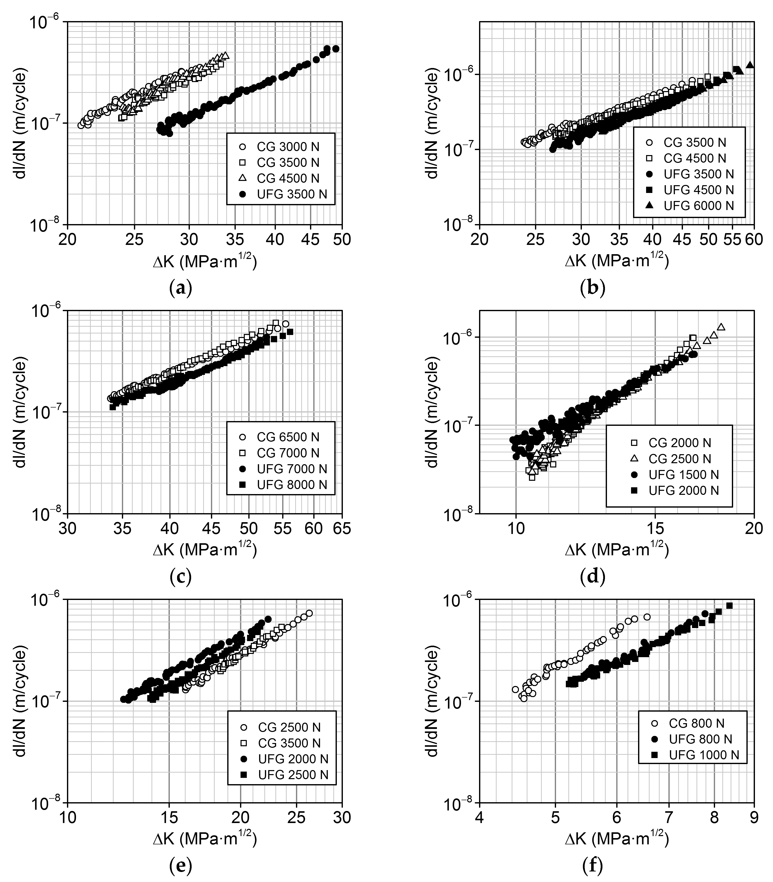
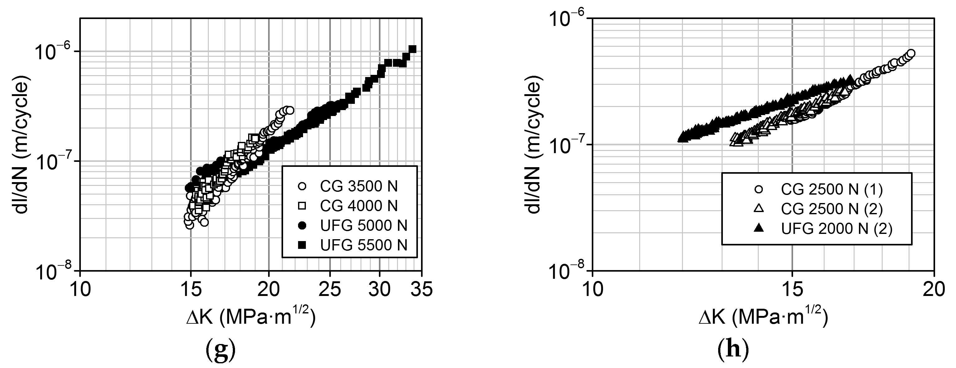
The analysis of the straight-line portion of the kinetic diagrams of fatigue fracture for the materials under study (Figure 3) shows that at the same value of the stress intensity coefficient range ( Δ K ), for most UFG materials under study, the fatigue crack propagation rate (dl/dN) is close to or even lower than that of the CG materials, irrespective of the crystal lattice type of the materials. The only exceptions are the Ti-6Al-4V titanium alloy (Figure 3e), where the fatigue crack propagation rate in the UFG alloy is marginally higher than in the CG alloy and the ENAW-2024 aluminum alloy, where the above-mentioned difference in the crack propagation rate is observed only at low values of the stress intensity coefficient ( Δ K ) (Figure 3h). This is probably related to the fact that for these CG alloys (alongside Ti), the total number of loading cycles to sample failure is larger than for the samples from the UFG alloys (Table 5).
The straight-line portion of the kinetic diagrams of fatigue fracture is described by the Paris equation [16]. Our analysis (Table 6) shows that for the CG and UFG steels with bcc lattices, the values of the coefficients n in the Paris equation are close (for the C45 and 12Cr-2W-2Ni-0.5Mo steels). For the 9MnSi5 steel, the value of the coefficient n is marginally lower in the UFG state than in the CG state. For all the materials under study with hcp and fcc lattices, the coefficient n is much lower in the UFG state than in the CG state (Table 6). The low value of the coefficient n in the UFG state, in comparison to the CG state, indicates that the UFG structure is less sensitive to cyclic overload [2,20,21,22].
Let us analyze these results and establish the fatigue fracture mechanisms of the materials under study in the central part of the fracture surfaces from the perspective of the crystal lattice type.
In the zone of fatigue crack propagation in the 9MnSi5 steel, irrespective of the steel’s state, microrelief consists predominantly of crystallographically oriented fragments, with some places showing fatigue striations and secondary cracks located parallel to them (Figure 4a,b). On the fracture surface of the steel with a CG structure (Figure 4a), the striations are clearly visible. In the ECAP-processed steel (Figure 4b) the striations are not clearly seen, but secondary cracks are clearly visible. The microreliefs of the fatigue fracture surfaces of the C45 steel in the CG and UFG states are similar, and consequently, their fracture mechanisms are similar, as well. In both cases, within the zone of fatigue crack propagation ductile fatigue striations and secondary cracks are visible (Figure 4c,d). As the fatigue crack grows in the CG 12Cr-2W-2Ni-0.5Mo steel, flat regions where ductile fatigue striations are visible on the surface at a large magnification occupy an ever larger area (Figure 4e). During the fracture of the samples from the UFG 12Cr-2W-2Ni-0.5Mo steel, in the central part of the fatigue zone there are visible ductile fatigue striations and secondary cracks parallel to the crack propagation front (Figure 4f).
On the fatigue fracture surfaces of CG Ti, one can observe flat fragments consisting of transcrystalline cleavage-like facets with sizes approximately coinciding with the grain size of CG Ti [23]. On the surface of the facets there are clearly visible fatigue striations and secondary cracks (Figure 4g). The fatigue fracture of UFG Ti, at all the stages of crack propagation, is characterized by the formation of a fine microrelief; ductile fatigue striations and secondary cracks are visible (Figure 4h). The fatigue fracture surface microrelief of the CG Ti-6Al-4V titanium alloy can be characterized as “scaly” or banded [24]. Such microreliefs are typical for the region of fatigue crack propagation in Ti-6Al-4V. On the surface of large scales, one can observe fatigue striations and secondary cracks (Figure 4i). The “scaly” microrelief is also preserved on the fracture surface of the UFG Ti-6Al-4V alloy. However, the scales are small; fatigue striations and secondary cracks are visible (Figure 4j). Within the fatigue zone, the fracture surface of the as-annealed CG Mg6Al alloy consists of transcrystalline cleavage-like facets (Figure 4k) with sizes approximately coinciding with the alloy’s grain size. The morphology of the facets is represented by equidistant, parallel tubes that have the same orientations within a facet. The formation of such a microrelief is accounted for by the formation of elongated pores in the form of tubes at the intersections of slip bands, and a subsequent rupture of the bridges between them [25]. The microrelief of the fatigue fracture surfaces of the Mg6Al alloy after ECAP processing is also characterized by a tubular morphology, but the tubes are fragmented (Figure 4l).
On the fatigue fracture surface of the CG Fe-0.02C-18Cr-8Ni austenitic steel, ductile fatigue striations and secondary cracks are visible (Figure 4m). On the fracture surface of the UFG steel, the quantity of secondary cracks increases manifold (Figure 4n). In austenitic steels, this may be attributed to the presence of carbide particles that, on the whole, have a negative effect on low-cycle fatigue resistance, leading to the formation of cracks and voids [26]. The fracture surface microrelief of the CG ENAW-2024 aluminum alloy may be characterized as a cyclic cleavage with tongues and steps clearly oriented along the crystallographic planes. There are areas with a dimple microrelief (Figure 4o). On the fatigue fracture surface of the UFG alloy, ductile striations alternate with the cyclic cleavage regions and dimple microrelief (Figure 4p).
Thus, it can be seen that the fatigue fracture surface microreliefs of the CG and UFG steels with bcc lattices are similar. Apparently, the fatigue fracture mechanisms of the CG and UFG steels are identical. In Ti and the Ti-6Al-4V titanium alloy (hcp lattice materials), strong refinement of the fragmental microrelief forming on the fracture surface of the UFG materials is observed, in comparison to CG materials (except the Mg alloy, where the ECAP-processed UFG state was not achieved); however, the fracture mechanisms of the fragments of the UFG and CG materials are similar. The fatigue fracture mechanisms of the CG and UFG materials with fcc lattices are also similar, although it is noteworthy that the fracture of the UFG materials is accompanied by the formation of many secondary cracks. The last remark is characteristic of the materials with bcc and hcp lattices, as well.

4. Discussion

This research shows that several parameters of the low-cycle fatigue of CG and UFG materials can be identified that are not significantly influenced by the type of the crystal lattice of materials. Among the parameters that are not significantly influenced, either by the crystal lattice type or the material state, is the number of loading cycles to fatigue crack initiation (Nin). As noted above, the number of cycles to fatigue crack initiation (Nin) in both the CG and UFG materials increases with the increasing total life of the samples (N). Percentage-wise, the Nin quantity at this geometry of the stress raiser in the samples amounts to about 20% of the total life of the samples, irrespective of the material state and the crystal lattice type (Figure 2).
Another parameter that is not significantly influenced by the crystal lattice type is the fatigue crack propagation rate (dl/dN) in the CG and UFG materials at the same value of the stress intensity coefficient range ( Δ K ). As noted above, at the same value of Δ K , for the majority of the UFG materials under study, irrespective of the crystal lattice type, the fatigue crack propagation rate (dl/dN) is close to or lower than in the CG materials (Figure 3). Without any doubt, the lower fatigue crack propagation rate in the majority of the UFG materials, irrespective of the crystal lattice type, favorably characterizes this class of materials in comparison to CG materials.
It should be noted that, irrespective of the crystal lattice type, there is a certain similarity between the fatigue fracture mechanisms of the CG and UFG materials (Figure 4).
As a parameter associated with the crystal lattice type, one may regard the total life of the samples from the CG and UFG materials tested at the same values of the cycle stress range (ΔP). The life of the samples from the UFG steels with bcc lattices is higher or marginally lower (at high loading cycles) than the life of the samples from the CG steels, while the life of the samples from the UFG materials with hcp and fcc lattices is lower than the life of the samples from the CG materials (Table 5).
A fatigue fracture parameter that depends on the type of crystal lattice of a material is the coefficient n in the Paris equation that characterizes the sensitivity of a material to cyclic overload. Research shows that for the CG and UFG steels with bcc lattices, the values of the coefficient n in the Paris equation are close to each other or marginally lower for the UFG steel than for the CG steel. For all the investigated materials with hcp and fcc lattices, the coefficient n is much lower for the UFG materials than for the CG materials (Table 6). Consequently, the materials in a UFG state are less sensitive to cyclic overload that may emerge during the operation of products.
This research has allowed us to establish certain regularities in the effect of crystal lattice type on the parameters of the cyclic fracture of the CG and UFG materials in the region of low-cycle fatigue. Increasing the range of the materials under study with bcc, hcp and fcc lattices could allow one to specify and experimentally justify these regularities.

5. Conclusions

  • The nanostructuring of the materials under study via ECAP processing has an ambiguous effect on the total number of cycles to failure during low-cycle fatigue tests of the samples.
  • The number of cycles to fatigue crack initiation (Nin) in both the CG and UFG materials increases with the increasing total life of the samples (N). Percentage-wise, the Nin quantity does not depend on the material state or the crystal lattice type.
  • At the same value of the coefficient ( Δ K ), for the majority of the investigated UFG materials, the fatigue crack propagation rate (dl/dN) is close to or lower than in the CG materials.
  • For the UFG materials, the values of the coefficient n in the Paris equation describing the straight-line portion of the kinetic diagram of fatigue fracture are either lower than or close to those for the CG materials. Consequently, the UFG materials are less sensitive to cyclic overload that may emerge during the operation of products.
  • The fatigue fracture mechanisms of the investigated materials in the CG and UFG states, in spite of certain differences associated with the crystal lattice type, are mostly similar, although the fracture of the UFG materials is accompanied by the formation of many secondary cracks.

Author Contributions

Conceptualization, G.V.K. and R.Z.V.; methodology, N.A.K.; validation, M.N.T. and I.N.P.; investigation, M.N.T., I.N.P. and D.A.A.; data curation, M.N.T. and I.N.P.; writing—original draft preparation, G.V.K.; writing—review and editing, R.Z.V. and D.A.A.; visualization, N.A.K.; supervision, G.V.K.; project administration, G.V.K.; funding acquisition, G.V.K. All authors have read and agreed to the published version of the manuscript.

Funding

This research was supported by a grant from the Russian Science Foundation (interdisciplinary project No. 20-69-47059 and, in part, project No. 20-63-47027).

Institutional Review Board Statement

Not applicable.

Informed Consent Statement

Not applicable.

Data Availability Statement

Not applicable.

Acknowledgments

The authors are grateful to Marina M. Abramova and other colleagues from Ufa University of Science and Technology (Ufa, Russia) for preparing the experimental samples for the study and assisting in the research.

Conflicts of Interest

The authors declare no conflict of interest.

References

  1. McEvily, A.J. Metal Failures: Mechanisms, Analysis, Prevention; Wiley & Sons: New York, NY, USA, 2002; 324p. [Google Scholar]
  2. Klevtsov, G.V.; Botvina, L.R.; Klevtsova, N.A.; Limar, L.V. Fractodiagnostics of the Fracture of Metallic Materials and Structures; MISIS: Moscow, Russia, 2007; 264p. [Google Scholar]
  3. Semenova, I.P.; Klevtsov, G.V.; Klevtsova, N.A.; Dyakonov, G.S.; Matchin, A.A.; Valiev, R.Z. Nanostructured titanium for maxillofaxial mini-implants. Adv. Eng. Mater. 2016, 18, 1216–1224. [Google Scholar] [CrossRef]
  4. Klevtsov, G.; Valiev, R.; Klevtsova, N.; Kulyasova, O.; Merson, E.; Linderov, M.; Ganeev, A. Kinetics and the fracture mechanism in low-cycle fatigue range and static crack resistance of the Mg6Al magnesium alloy after annealing and equal channel angular pressing. Lett. Mater. 2020, 10, 398–403. [Google Scholar] [CrossRef]
  5. Valiev, R.Z.; Zhilyaev, A.P.; Langdon, T. G Bulk Nanostructured Materials: Fundamentals and Applications; TMS/Wiley: Hoboken, NJ, USA, 2014; 440p. [Google Scholar]
  6. Chung, C.; Kim, J.; Kim, H.; Kim, W. Improvement of high-cycle fatigue life in a 6061 Al alloy produced by equal channel angular pressing. Mater. Sci. Eng. A 2002, 337, 39–44. [Google Scholar] [CrossRef]
  7. Vinogradov, A.; Nagasaki, S.; Patlan, V.; Kitagawa, K.; Kawazoe, M. Fatigue properties of 5056 Al-Mg alloy produced by equal-channel angular pressing. Nanostruct. Mater. 1999, 11, 925–934. [Google Scholar] [CrossRef]
  8. Pao, P.; Jones, H.; Cheng, S.; Feng, C. Fatigue crack propagation in ultrafine grained Al–Mg alloy. Int. J. Fatigue 2005, 27, 1164–1169. [Google Scholar] [CrossRef]
  9. Cavaliere, P. Fatigue properties and crack behavior of ultra-fine and nanocrystalline pure metals. Int. J. Fatigue 2009, 31, 1476–1489. [Google Scholar] [CrossRef]
  10. Kim, H.-K.; Choi, M.-I.; Chung, C.-S.; Shin, D.H. Fatigue properties of ultrafine grained low carbon steel produced by equal channel angular pressing. Mater. Sci. Eng. A 2003, 340, 243–250. [Google Scholar] [CrossRef]
  11. Hanlon, T.; Tabachnikova, E.; Suresh, S. Fatigue behavior of nanocrystalline metals and alloys. Int. J. Fatigue 2005, 27, 1147–1158. [Google Scholar] [CrossRef]
  12. Meyer, L.W.; Sommer, K.; Halle, T.; Hockauf, M. Crack growth in ultrafine-grained AA6063 produced by equal-channel an-gular pressing. J. Mater. Sci. 2008, 43, 7426–7431. [Google Scholar] [CrossRef]
  13. Estrin, Y.; Vinogradov, A. Fatigue behavior of light alloys with ultrafine grain structure produced by severe plastic deformation: An overview. Int. J. Fatigue 2010, 32, 898–907. [Google Scholar] [CrossRef]
  14. Vinogradov, A. Fatigue limit and crack growth in ultra-fine grain metals produced by severe plastic deformation. J. Mater. Sci. 2006, 42, 1797–1808. [Google Scholar] [CrossRef]
  15. Broek, D. Elementary Engineering Fracture Mechanics; Noordhoff International Publishing: Leyden, The Netherlands, 1974; 408p. [Google Scholar]
  16. Paris, P.; Erdogan, F. A Critical Analysis of Crack Propagation Laws. J. Basic Eng. 1963, 85, 528–533. [Google Scholar] [CrossRef]
  17. Valiev, R.Z.; Straumal, B.; Langdon, T.G. Using Severe Plastic Deformation to Produce Nanostructured Materials with Superior Properties. Annu. Rev. Mater. Res. 2022, 52, 357–382. [Google Scholar] [CrossRef]
  18. Islamgaliev, R.K.; Nikitina, M.A.; Ganeev, A.V.; Sitdikov, V.D. Strengthening mechanisms in ultrafine-grained ferrit-ic/martensitic steel produced by equal channel angular pressing. Mater. Sci. Eng. A 2019, 744, 163–170. [Google Scholar] [CrossRef]
  19. Klevtsov, G.V.; Merson, D.L.; Klevtsova, N.A.; Merson, E.D.; Linderov, M.L.; Zasypkin, S.V.; Bondarenko, A.V. The kinetics and mechanism of fatigue fracture of samples of 40H and 38H2N2MA steels. Sci. Vector Togliatti State Univ. 2019, 1, 30–36. [Google Scholar] [CrossRef]
  20. Kocańda, S. Fatigue Cracking of Metals; Metallurgiya: Moscow, Russia, 1990; 623p. [Google Scholar]
  21. Botvina, L.R. Fracture: Kinetics, Mechanisms, General Regularities; Nauka: Moscow, Russia, 2008; 334p. [Google Scholar]
  22. Ueno, H.; Kakihata, K.; Kaneko, Y.; Hashimoto, S.; Vinogradov, A. Enhanced fatigue properties of nanostructured austenitic SUS 316L stainless steel. Acta Mater. 2011, 59, 7060–7069. [Google Scholar] [CrossRef]
  23. Semenova, I.P.; Modina, Y.M.; Stotskiy, A.G.; Polyakov, A.V.; Pesin, M.V. Fatigue Properties of Ti Alloys with an Ultrafine Grained Structure: Challenges and Achievements. Metals 2022, 12, 312. [Google Scholar] [CrossRef]
  24. Ren, Y.; Lin, X.; Guo, P.; Yang, H.; Tan, H.; Chen, J.; Li, J.; Zhang, Y.; Huang, W. Low cycle fatigue properties of Ti-6Al-4V alloy fabricated by high-power laser directed energy deposition: Experimental and prediction. Int. J. Fatigue 2019, 127, 58–73. [Google Scholar] [CrossRef]
  25. Meyn, D.A.; Brooks, E.J. Microstructural origin of flutes and their use in distinguishing striationless fatigue cleavage from stress-corrosion cracking in titanium alloys. In Fractography and Materials Science; ASTM STP, 733, Gilbertson, L.N., Zipp, R.D., Eds.; American Society for Testing Materials: Philadelphia, PA, USA, 1981; pp. 5–31. [Google Scholar]
  26. Oh, Y.-J.; Hwang, T.-B.; Shin, B.M. A Comparison of Low-cycle Fatigue Properties in Stainless Steel Types 347N and 316N. Mater. Trans. 2005, 46, 317–322. [Google Scholar] [CrossRef] [Green Version]
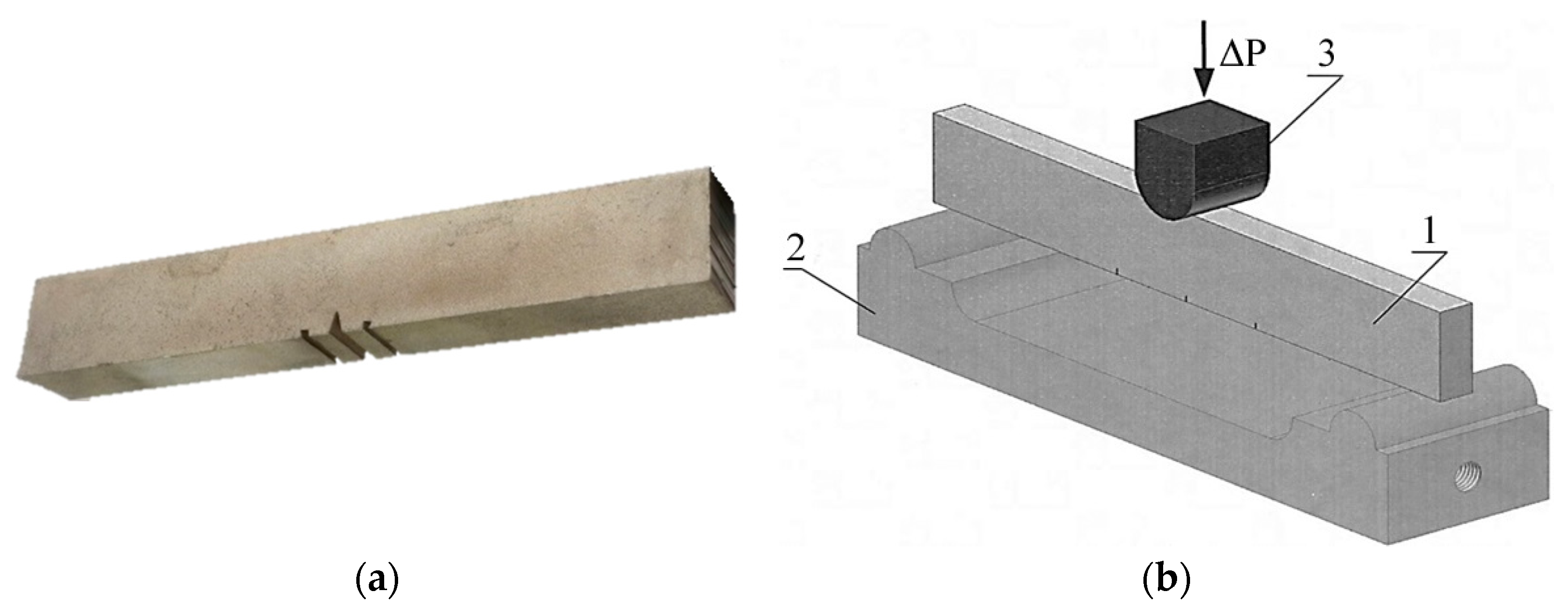
Figure 1. Sample (a) and the principle of the fatigue tests of the samples via three-point bending (b). The element labeled 1 is the sample, 2 is the bottom support, and 3 is the loading support.
Metals 13 00709 g001
Figure 2. Dependence of the number of loading cycles to fatigue crack initiation, Nin, on the total life of samples, N (a), and its percentage vs. the total life of samples (b). The initial CG materials are indicated by bright marks; the materials processed by equal-channel angular pressing (ECAP) are indicated by dark marks.
Metals 13 00709 g002
Figure 3. Straight-line portions of the kinetic diagrams of fatigue fracture for the materials with body-centered cubic (bcc) lattices: the 9MnSi5 (a), C45 (b) and 12Cr-2W-2Ni-0.5Mo (c) steels; hexagonal close-packed (hcp) lattices: Grade 4 Ti (d), a Ti-6Al-4V titanium alloy (e) and a Mg6Al magnesium alloy (f); face-centered cubic (fcc) lattices: Fe-0.02C-18Cr-8Ni steel (g), and an ENAW-2024 aluminum alloy (h); in the initial CG state (bright dots) and in the ECAP-processed state (dark dots).
Metals 13 00709 g003aMetals 13 00709 g003b
Figure 4. Characteristic fatigue fracture surface microreliefs of the materials with bcc lattices: 9MnSi5 steel (a,b), C45 steel (c,d), 12Cr-2W-2Ni-0.5Mo steel (e,f); hcp lattices: Grade 4 Ti (g,h), a Ti-6Al-4V titanium alloy (i,j), a Mg6Al magnesium alloy (k,l); fcc lattices: Fe-0.02C-18Cr-8Ni steel (m,n), and an ENAW-2024 aluminum alloy (o,p); in the initial CG state (a,c,e,g,i,k,m,o) and after ECAP (b,d,f,h,j,l,n,p). The microreliefs were obtained in the middle part of the zone of fatigue crack propagation, lf. The fatigue crack propagation direction is from left to right. (a,b) ×6000; (c) ×3500; (d,i,j) ×5000; (e,f) ×10,000; (g,o,p) ×1000; (h,m,n) ×2000; (k,l) ×500.
Metals 13 00709 g004aMetals 13 00709 g004b
Table 1. Chemical composition of steels (in wt.%).
SteelCCrNiMnMoSiCuCoAlWV
C450.45----------
9MnSi50.090.080.11.26-0.640.14-0.02--
12Cr-2W-2Ni-0.5Mo0.1411.531.630.320.450.31---1.660.18
Fe-0.02C-18Cr-8Ni0.02317.957.95 1.850.350.380.60.15---
Table 2. Chemical composition of Grade 4 Ti, the Ti-6Al-4V titanium alloy and the Mg6Al magnesium alloy (in wt.%).
AlloyAlVZrSiFeCMnClCaNHO
Grade 4 Ti----0.380.008---0.0030.00060.32
Ti-6Al-4V6.64.90.020.0330.180.007------
Mg6Al6.0-----0.2450.04740.0459---
Table 3. Chemical composition of the ENAW-2024 aluminum alloy (in wt.%).
AlloyCuMgNiSiFeMnCrZnTi
ENAW-20242.321.651.040.060.100.0470.0030.0170.020
Table 4. Mean grain size (dmean) and tensile mechanical properties of the materials under study.
MaterialLattice TypeStatedmean, μmHBσB, MPaσ0.2, MPaδ, %
9MnSi5bccCG (initial)10143485 ± 3354 ± 1125 ± 1.5
UFG (ECAP)0.45331838 ± 12655 ± 6410 ± 1.0
C45bccCG (quenching and tempering)10302985 ± 15839 ± 1716 ± 0.8
UFG (ECAP)0.56346985 ± 12839 ± 255 ± 1.5
12Cr-2W-2Ni-0.5MobccCG (quenching and tempering)30311950 ± 10790 ± 157.0 ± 1.5
UFG (ECAP and quenching)1.33521350 ± 201200 ± 206.0 ± 1.0
Grade 4 TihcpCG (annealing)25255750 ± 10650 ± 3020 ± 0.5
UFG (ECAP)0.43111050 ± 15900 ± 2514 ± 0.7
Ti-6Al-4VhcpCG (initial)1534950 ± 20849 ± 3012 ± 1.5
UFG (ECAP)0.24361090 ± 30990 ± 408 ± 0.3
Mg6AlhcpCG (annealing)8548230 ± 1075 ± 58.5 ± 1.5
CG (ECAP)2060260 ± 15100 ± 1010 ± 1.0
Fe-0.02C-18Cr-8NifccCG (initial)30159624 ± 6283 ± 265 ± 0.7
UFG (ECAP)0.553631112 ± 151065 ± 1520 ± 0.5
ENAW-2024fccCG (T6)40122370 ± 12320 ± 1016 ± 1.0
UFG (ECAP)0.3126460 ± 15420 ± 188 ± 1.0
Table 5. Total number of loading cycles to failure for the samples from some of the coarse-grained (CG) and ultrafine-grained (UFG) materials under study with equal cycle stresses ΔP.
MaterialLattice TypeCG or UFG StateΔP, N
800200025003500450055007000
9MnSi5bccCG---6.77 × 10⁴---
UFG---2.30 × 10⁵---
C45 steelbccCG---1.33 × 1055.89 × 1043.58 × 104-
UFG---1.31 × 1055.28 × 1042.90 × 104-
12Cr-2W-2Ni-0.5MobccCG------2.14 × 10⁴
UFG------2.45 × 10⁴
Grade 4 TihcpCG-1.13 × 10⁵-----
UFG-3.91 × 10⁴-----
Ti-6Al-4VhcpCG--1.18 × 1053.13 × 104---
UFG--5.76 × 1041.88 × 104---
Mg6AlhcpCG6.32 × 104------
CG (ECAP)5.09 × 10⁴------
ENAW-2024fccCG-1.52 × 1058.20 × 104----
UFG-6.10 × 1044.03 × 104----
Table 6. Paris equations for the materials under study in the CG and UFG states.
MaterialLattice TypeCGUFG
9MnSi5 steelbcc d l d N = 2.8 × 10 12 Δ K 3.5 d l d N = 3.4 × 10 12 Δ K 3.1
C45 steelbcc d l d N = 1.1 × 10 12 Δ K 3.0 d l d N = 5.7 × 10 12 Δ K 3.1
12Cr-2W-2Ni-0.5Mo steelbcc d l d N = 5.9 × 10 13 Δ K 3.6 d l d N = 4.4 × 10 13 Δ K 3.5
Grade 4 Tihcp d l d N = 4.2 × 10 15 Δ K 6.8 d l d N = 4.3 × 10 13 Δ K 5.2
Ti-6Al-4V titanium alloyhcp d l d N = 7.6 × 10 12 Δ K 3.6 d l d N = 2.5 × 10 11 Δ K 3.3
Mg6Al magnesium alloyhcp d l d N = 8.9 × 10 11 Δ K 4.8 d l d N = 3.6 × 10 10 Δ K 3.7
Fe-0.02C-18Cr-8 Niaustenitic steelfcc d l d N = 3.3 × 10 15 Δ K 6.0 d l d N = 7.2 × 10 12 Δ K 3.5
ENAW-2024 aluminum alloyfcc d l d N = 3.2 × 10 13 Δ K 5.0 d l d N = 5.2 × 10 11 Δ K 3.1
Disclaimer/Publisher’s Note: The statements, opinions and data contained in all publications are solely those of the individual author(s) and contributor(s) and not of MDPI and/or the editor(s). MDPI and/or the editor(s) disclaim responsibility for any injury to people or property resulting from any ideas, methods, instructions or products referred to in the content.