Article

A Study on the Dynamic Evolution Mechanism of the Steady Magnetic Field on the Internal Flow Behavior of a Laser Melting Pool

1
Automobile Technology School, Zhejiang Technical Institute of Economics, Hangzhou 310018, China
2
Institute of Laser Advanced Manufacturing, Zhejiang University of Technology, Hangzhou 310014, China
3
Zhejiang Provincial Collaborative Innovation Center of High-End Laser Manufacturing Equipment, Hangzhou 310014, China
*
Author to whom correspondence should be addressed.
Metals 2023, 13(4), 720; https://doi.org/10.3390/met13040720
Submission received: 14 February 2023 / Revised: 2 April 2023 / Accepted: 3 April 2023 / Published: 6 April 2023
(This article belongs to the Section Computation and Simulation on Metals)

Abstract

:
A 2D model of laser melting consisting of heat transfer, hydrodynamic flow, surface tension, and a free surface motion was established. A physical field simulation of the laser melting process was performed, and the effect of steady magnetic field parameters on the internal flow and temperature fields of the melt pool was analyzed and validated by experiments. The results show that the steady magnetic field can suppress the melt pool flow rate, but slightly influences its temperature field, and with an increase in the magnetic field strength, the ripples on the melting surface decrease with increasing magnetic flux density. Compared with the molten pool depth experiment results, the simulation molten pool depth was 792 μm, representing a difference in value of 13.5%. The surface ripples of the molten pool fluctuated greatly in the absence of a magnetic field, while the surface ripples were suppressed when the magnetic flux density was 2T. This is consistent with the simulation results, thus effectively demonstrating the simulation model’s accuracy.

1. Introduction

Currently, laser processing technology has been widely used in additive manufacturing, polishing, welding, cutting, and other areas of material precision processing [1]. Metal surface melting has formed many advanced manufacturing processes, such as direct metal deposition (DMD), laser net-forming (LENS), laser metal deposition (LMD), selective laser melting (SLM), laser polishing, etc., allowing new prospects for high-performance products in material processing and laser fusion manufacturing. Laser melting is one of the methods of laser surface strengthening. It has the characteristics of fast heating and cooling and can improve the mechanical properties of materials by changing their surface properties without changing their composition [2,3,4,5]. For example, Li et al. studied the quality and mechanical properties of Ti6Al4V selected-area laser melting and forming [6]. With an increase in the number of lasers remelting, the upper surface quality and denseness of the Ti6Al4V sample parts gradually improved, and the surface roughness also improved. Laser melting is more complex, and the internal flow behavior of the laser melting pool significantly influences the growth rate of the pool temperature gradient and solidification interface, the transformation of liquid and solid phases, and the scale shape and properties [7]. The effective thermal conductivity approach, which is an alternative way to characterize the heat transfer effects of motion within the molten metal, has been successfully applied to other metallurgical processes [8]. However, there are challenges with laser melting and coagulation treatment. Due to the reflux effect of the melt pool, the laser melting surface can easily form ripples or folds, which extremely reduces the quality of the melting surface and requires subsequent machining, etc. Therefore, it is important to study and understand the surface morphology after laser-melting solidification to reduce surface roughness and the subsequent machining.
In response to the above problems, scholars have proposed the adoption of measures such as a steady magnetic field, an electromagnetic compound field, ultrasonic vibration, mechanical vibration, etc., to change the flow behavior of the laser melt pool [9,10,11,12]. Particularly, the steady magnetic field’s regulating effect on the laser melt pool can be applied in many areas as an auxiliary technology with outstanding features, such as non-contact, non-pollution, controllability, and various combinations. In recent years, researchers have widely applied this technology to laser welding, laser melting, and laser polishing processes [13,14]. The use of laser melting in practical engineering applications requires process parameters that meet the expected product quality standards, but due to a large number of process parameters and the coupling between various physical phenomena, determining process parameters through experiments is costly and time-consuming. Therefore, simulations are a promising alternative to save cost and time in experiments and can also be used to reduce exploration costs [15,16,17]. In addition, numerical simulation enhances the understanding of the auxiliary transport phenomena in laser material processing, making it easier to compare laser process control parameters and multiple factors. With the development of computational techniques, numerical simulations can also exhibit sufficient predictive capabilities that are also difficult to obtain experimentally.
Many researchers have effectively studied the numerical simulation of electromagnetic field-assisted laser processing. Liu et al. investigated the evolution of the macroscopic morphology of laser melting coating using alternating magnetic fields, and the results showed that the alternating electromagnetic force caused the surface morphology of the melting layer to be wavy after solidification [18]. Elsewhere, Wang et al. numerically simulated the electromagnetic, temperature, and flow fields of the laser melt pool under electromagnetic stirring; they also experimentally studied the effects of magnetic field stirring on the microstructure and properties of laser-deposited titanium alloys, obtaining a refined lamellar microstructure and improving the mechanical properties of the deposited layer [19]. In a different study, Wang et al. studied the induced Lorentz force effect on the distribution of Fe elements in laser-clad Inconel718 coatings and established a three-phase mixed solidification model based on the averaging method [20]. Yu et al. used the finite element and finite volume methods to numerically analyze the coupled magnetic-thermal-fluid analysis of laser-additive manufacturing of Ni45 alloy under the action of alternating magnetic fields and explored the evolution pattern of the applied magnetic fields on the solidification microstructure and properties [21]. Hu et al. established a multi-physics mathematical model of steady magnetic-field-assisted laser melting and solidification to simulate the velocity and temperature fields of the melt pool under a steady magnetic field [22]. Furthermore, Wang et al. established a mathematical model of the regulation of the electromagnetic complex field on the gradient of the particle distribution enhanced by laser melting and injection and analyzed the influence of the electromagnetic complex field parameters on the flow field, temperature field, and particle distribution inside the melt pool [23]. To improve the rough surface of SKD61 die steel, and reduce the secondary overflow of the molten pool, Zhou et al. adopted a steady magnetic-field-assisted laser-polishing method to study the effect of a steady magnetic field on surface morphology and melt pool flow behavior [24]. The study revealed that the steady magnetic field can inhibit the secondary overflow of the molten pool to slightly improve SKD61 surface roughness by reducing the velocity of the molten pool. Gruzd et al. experimentally and theoretically evaluated the refinement of the micro-optical structure of stainless steel in the applied magnetic field laser surface processing [25]. The authors discussed the effect of cross-surface magnetic fields and permanent magnetic fields and also simulated the transport phenomenon in the melting zone. Bachmann et al. improved the quality of the weld seam and the strength of the laser welding process by controlling the electromagnetic field-controlled flow in the molten pool [26]. Meng and co-workers [27] studied the effect of electromagnetic stirring on fluid flow and element transport in wire-fed laser welding and showed that the Lorentz force generated by the oscillating magnetic field and its induced eddy currents significantly influenced the fluid flow and hole lock stability. Moreover, electromagnetic stirring behind and below the melt pool improved the flow rate of the melt. From preceding discussions, the surface tension and free surface motion of the laser melting and condensing melt pool under a steady magnetic field have not been comprehensively studied and still merit significant further research.
Therefore, in this paper, we established a multi-physics mathematical model of the internal flow of a laser melting pool under a steady magnetic field and simulated the dynamic evolution mechanism of the velocity field, flow field, surface tension, and free surface motion of the melt pool under a steady magnetic field using COMSOL Multiphysics. The simulated and experimental results were compared and analyzed.

2. Numerical Model

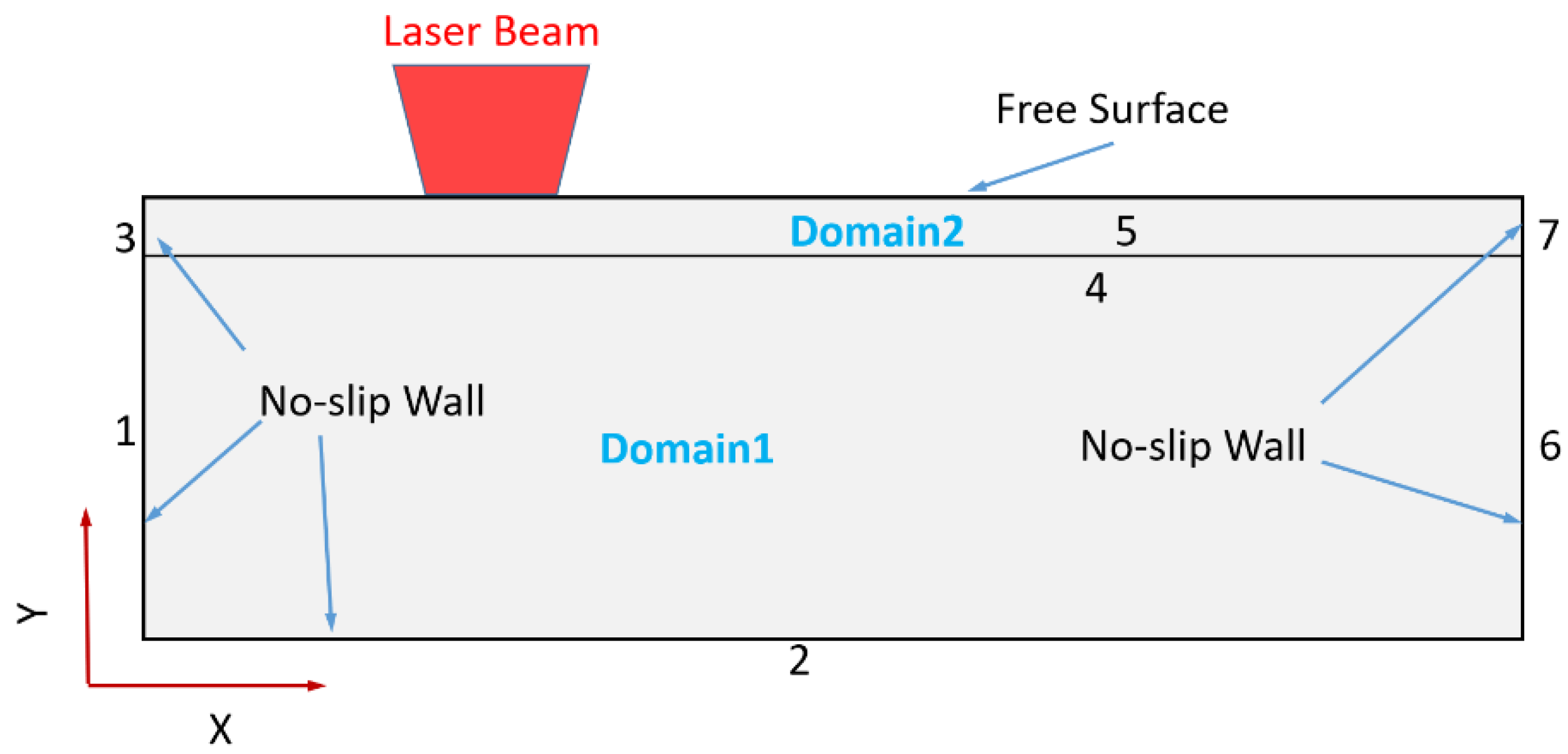
2.1. Geometric Model

The 2D model with a size of 25 mm × 8 mm was used in this study, as shown in Figure 1. Since the laser melting layer depth is generally shallow, the model was layered to reduce the calculation volume, and the layer thickness was 0.5 mm.

2.2. Physical Model and Assumptions

Under the action of a laser, the laser beam radiates energy to the metal surface, and under laser irradiation, the metal surface reaches melting temperature to form a melt pool. The process of a laser melt pool under a steady magnetic field involves various physical processes, such as solid–liquid phase change of the material, heat transfer and convection of the melt pool, surface tension, the free surface motion of the melt pool, etc., which involve the coupling of several physical fields, so COMSOL Multiphysics software was used for the simulations.
The following assumptions are made in this model to clearly express the flow process of the metal during heating:
(1) The liquid metal in the molten pool is an incompressible Newtonian fluid;
(2) The material is homogeneous and isotropic, and the thermophysical parameters of the metal are only temperature-dependent;
(3) Air has little effect on the final shape of the melt pool surface, so the air domain is ignored to reduce the workload;
(4) The absorption of laser radiation at the surface of the material is an empirical value without regard to the influence of the incident laser and the normal angle of the surface;
(5) The model uses a boundary heat source acting directly on the metal surface, so the effect of the amount of defocusing on the melt pool is not considered and the depth of focus effect is ignored;
(6) The magnetic flux density B is uniformly distributed on the substrate in a direction perpendicular to the substrate axially and parallel to the surface of the molten coagulation layer.

2.3. Governing Equations

In the laser melting and solidification process, the material melts under the irradiation of the laser beam, and a melt pool appears. Three regions exist in the melting or solidification process of the material: the solid-phase region, the liquid-phase region, and the solid/liquid coexistence region (paste region). The phase change occurs at a certain temperature range, and the thermophysical properties of the material vary with the temperature. In this paper, both solid and liquid phases are considered porous continuums. The heat transfer equation is solved in the two-phase domain to accurately obtain the phase change interface, and the phase change potential is added by correcting the heat capacity C p and applied to the simulation of the paste-like region around the phase change interface with the following control equation:
ρ C p T t + u T k T = 0
ρ u t = p + μ 2 u + F v
F v = F G r a v i t y + F B u o y a n c y + F D a r c y + F L o r e n t z = ρ g 1 β T T r e f A 1 f l 2 f l 3 + B u + j × B
j = σ e u × B
where ρ is the fluid density, g is the gravitational acceleration constant, β is the thermal expansion coefficient, T r e f is the reference temperature, p is the pressure, μ is the kinetic viscosity, F v is the bulk force including gravity ( F G r a v i t y ), buoyancy ( F b u o y a n c y ), Darcy resistance ( F D a r c y ) and Lorentz force ( F L o r e n t z ). t , k , u , j , B , and σ e are the laser heating time, thermal conductivity, flow rate of the melt pool, current density, magnetic flux density, and electrical conductivity of the material, respectively. The mass control equation for an incompressible fluid is:
u = 0
In this paper, we studied the process of continuous laser melting of 316L stainless steel, which is solved in a single domain, such as solid and liquid phases. The equivalent heat capacity C p is used instead of the specific heat capacity considering the influence of latent heat in the melting process:
C p = C p + L m d f l d T
where T is the temperature, C p is the specific heat capacity, L m is the latent heat of melting, and f l is the liquid phase fraction.
During the laser heating process, the surface of the metallic material undergoes a heating melting followed by an evaporation process. The simulation was performed at a temperature lower than the evaporation; in this case, only the heating phase and the melting phase were considered. Moreover, the liquid phase temperature line was slightly determined above the melting point of the material and the solid phase temperature line slightly below the melting point of the material to improve the stability of the numerical simulation. The liquid fraction was defined as follows:
f l = 0 , T < T s T T s T l T s ,     T s T T l 1 , T > T l

2.4. Moving the Grid

The model calculation area was divided into solid and liquid, and the deformation of the free surface of the melt pool liquid used the Arbitrary Lagrangian–Eulerian (ALE) method, which has the advantage that the solution of the grid equation can be used to smoothly replace the grid nodes divided in the flow field, combined with the moving coordinate system in the N-S equation to calculate the velocity of the melt pool interface at any point in time. The method not only handles flows with large deformations but also accurately describes the internal motion within the fluid with the following formula:
u m e s h n = u n
where u m e s h is the grid velocity and u is the velocity of the material flow calculated with the Navier–Stokes equations.

2.5. Boundary Conditions

(1) Heat transfer boundary conditions
The metal surface not only directly absorbs the radiation of the laser beam but also processes thermal convection and thermal radiation while heating the surrounding environment, which cannot be ignored as it will affect the changes in the temperature field. Thermal convection and radiation equations are as follows:
k T = Q + h T a m b T + ε σ T a m b 4 T 4
where Q is the heat generated by the laser beam, h is the convective heat transfer coefficient, ε is the surface emissivity, σ is the Stephen Boltzmann constant, and T a m b is the ambient temperature.
The laser beam power density distribution is a flat-top distribution, as shown in Equation (10):
Q x , t = P π r p ; x - v s t r p 0 ,       x - v s t > r p
where P is the laser power, r p is the spot radius, ( x , t ) is the laser beam position, and v s is the laser moving speed.
(2) Surface tension
Under laser melting, the surface tension of the melt pool γ dominates the pool flow and surface deformation, and in terms of effects, the surface tension can generate capillary forces along the normal direction σ n and Marangoni forces along the tangential direction of the free surface. The capillary force σ t and the Marangoni force σ n act as stresses on the free surface of the melt pool [28].
The total stress at the top of the melt pool is:
σ = σ n σ t = κ γ n γ T s T t
where γ is the surface tension coefficient, κ is the curvature of the surface profile, and γ / T is the temperature coefficient of surface tension, whose positive or negative value determines the direction of melt pool flow. If γ / T > 0 , the melt pool flows radially from the edge to the center. Otherwise, the melt pool flows radially from the center to the edge [29]. s T is the temperature gradient along the tangential direction of the surface and n and t are the normal and tangential vectors of the free-form surface, respectively.
The specific boundary conditions set in the physical field are shown in Table 1.
The physical properties of 316L stainless steel refer to 304 stainless steel. The parameters for the calculations are shown in Table 2.

2.6. Grid Division

The simulation uses the direct solver PARDISO. In the process of melt pool simulation, the influence of high-quality mesh is very important to the results of the calculation, and the triangular mesh is easier to converge, so the triangular mesh was used in domain 2. To reduce the calculation volume, a larger mesh was used in domain 1. Theoretically, the smaller the grid size, the longer the calculation time of melting, and the better the accuracy of the numerical simulation results. Since boundary 5 is a free-flowing surface of the melt pool, the boundary will be deformed when the material reaches the melting temperature, so a finer grid is needed for the calculation, and domain 2 of this model uses adaptive grid refinement.

3. Laser Melting Experiments

3.1. Laser Melting Experimental Setup

The experimental study was used to validate the numerical model of the molten pool dynamics evolution mechanism of the steady magnetic field in the internal flow. The schematic diagram is shown in Figure 2. The continuous laser used in this experiment was the fiber-coupled semiconductor laser producer (model: LDF400-2000), with a maximum laser power of 2000 W, a central radiation wavelength of 940~980 nm, a spot diameter of 4 mm, and a flat-top laser spot type. By applying a steady-state magnetic field on both sides of the substrate to obtain the Lorentz force, the substrate was polished, degreased, and dried before laser melting.
A Zeiss optical microscope (Model: Axio lmager2) was used to analyze the molten pool morphology of the continuous laser melting. The ultra-deep 3D microscope (Model: VHX-500) and the confocal laser scanning microscope (Model: VK-X1000), both manufactured by Keyence, Japan, were used to obtain the microscopic 3D morphology of the surface before and after continuous laser melting.

3.2. Experiment Materials

316L stainless steel was used in the experiment. Table 3 summarizes the basic chemical composition. The substrate surfaces were sanded with sandpaper before the experiment, the oil stains were removed with acetone, and then the surface was sonicated and finally dried. The melting samples were cut in the scanning direction, and the depth of the longitudinal section was observed under a metallurgical microscope after laser melting.

4. Numerical Simulation Results and Analysis

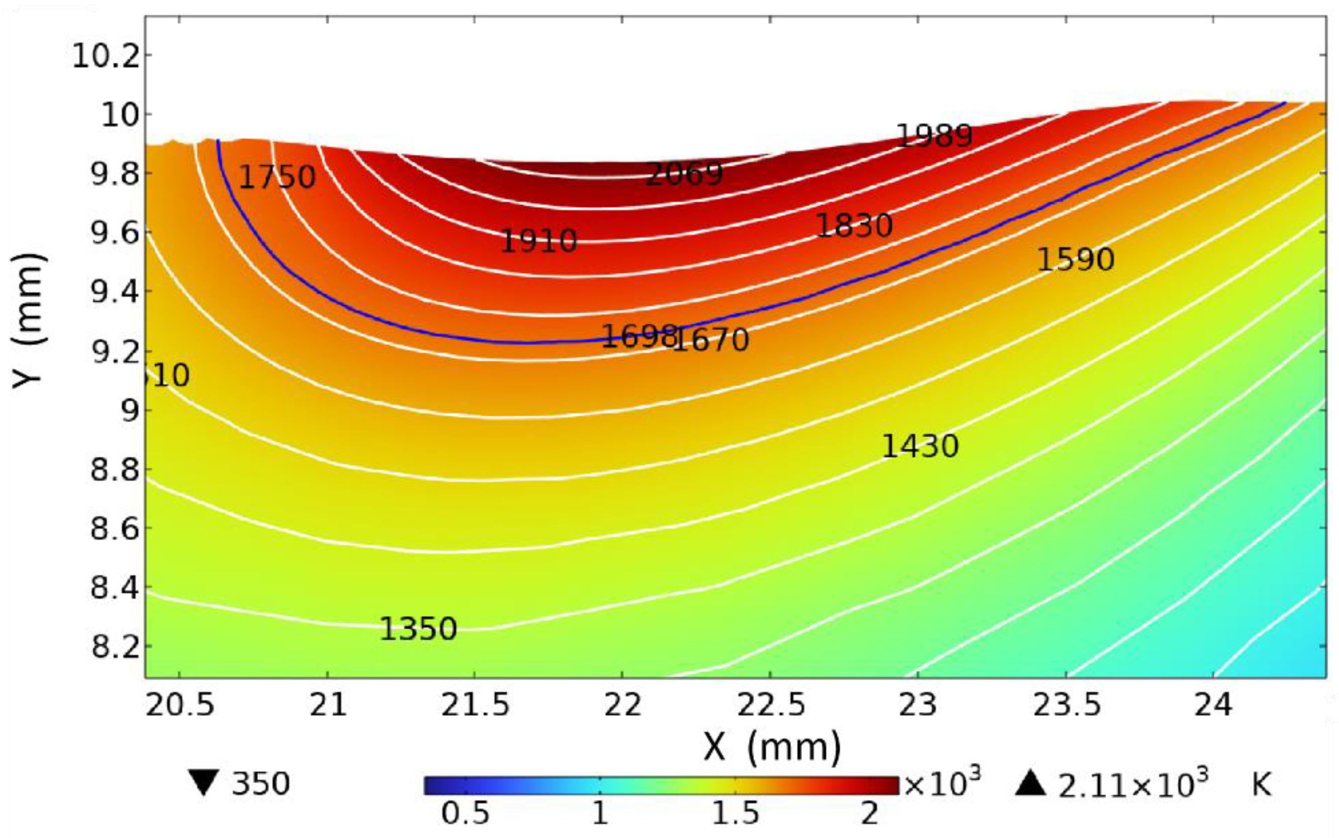
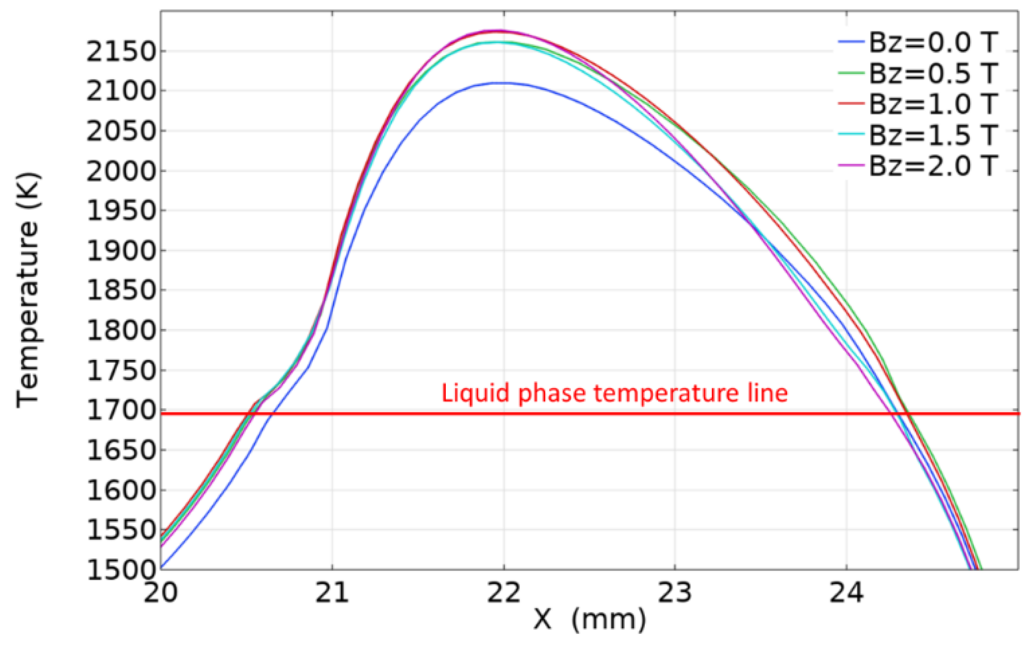
4.1. Effect of Magnetic Field Strength on Laser Melting Temperature Field

As shown in Figure 3, the energy of the laser beam is flat-topped circular and the material is assumed to be isotropic when no magnetic field is applied, which leads to a circular isotherm at the highest temperature attachment on the upper surface. As the laser heat source moves in the scanning direction, the isotherms are elongated. A sparse temperature distribution appears in the first half and a tighter temperature distribution in the latter due to the flat-top laser heating source. The temperature distribution on the surface of the laser melting pool increases with time, the surface shows a temperature gradient distribution along the pool from the center to the edge during the process of reaching the melting temperature, and the temperature at the center of the pool surface is higher than that of at the edge.
Figure 4 shows the temperature field distribution in the longitudinal section of the molten pool (t = 4.5 s) when steady magnetic fields of different strengths are applied. As Figure 5 shows, an increase in the intensity of the applied steady magnetic field slows down the flow rate on the molten pool surface, and the high-temperature liquid on the molten pool surface cannot be stirred into the melt pool interior under surface tension due to the continuous weakening of the convective heat transfer process in the molten pool. Therefore, the molten pool absorbs the same laser energy in the continuous melting and coagulation process under the same laser process parameters, which leads to an increase in the molten pool surface temperature under the applied steady magnetic field. However, under the applied magnetic field, the molten pool’s size and internal temperature distribution increased slightly. Whereas the surface temperature of the molten pool is 2110 K when the steady magnetic field is not applied, the near-surface temperature of the molten pool rises to 2174 K when the steady magnetic field (Bz = 1.0 T) is applied. As shown in Figure 5a–e, the red arrows represent the direction of fluid flow, and the length of the red arrows represent the magnitude of fluid velocity. This indicates that the surface flow field velocity of the molten pool decreases under the applied magnetic field. The surface temperature of the molten pool has increased, but the increase in temperature is not significant because inside the molten pool conduction heat transfer is predominant and the steady magnetic field has a greater impact on the internal thermal convection process of the molten pool. However, changing the temperature distribution inside the molten pool is difficult.

4.2. Effect of Magnetic Field Strength on the Flow Field of the Laser Melt Pool

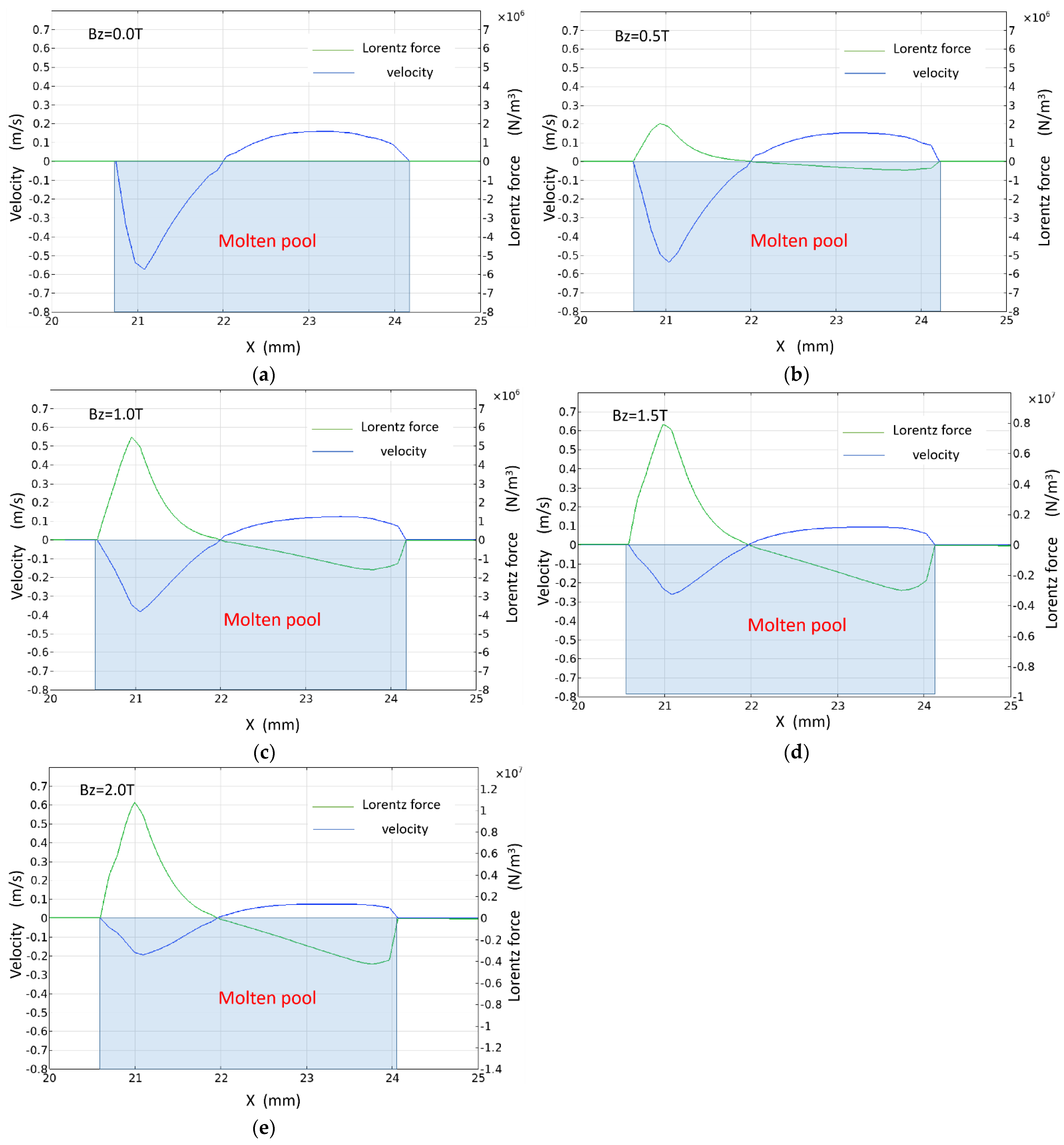
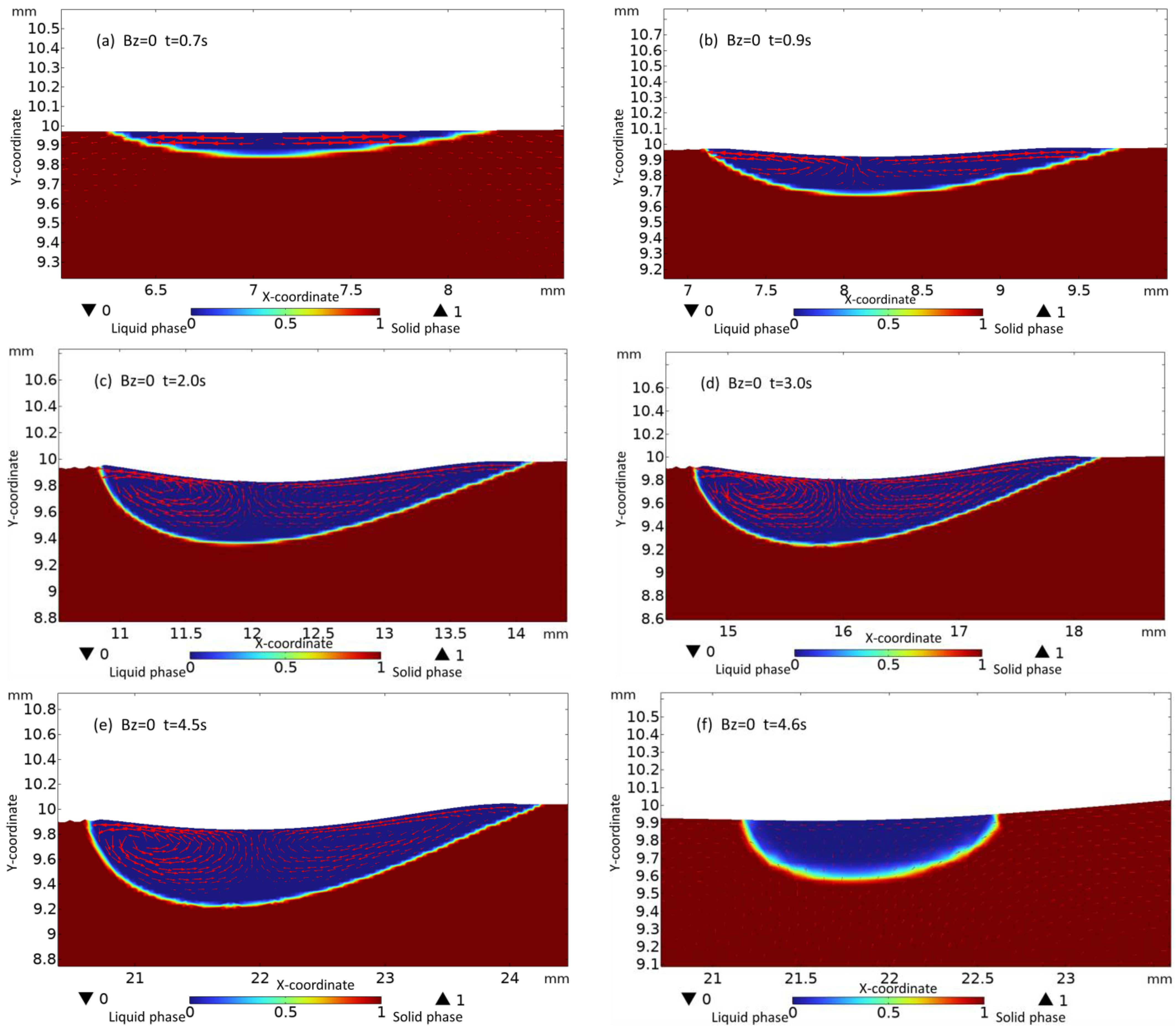
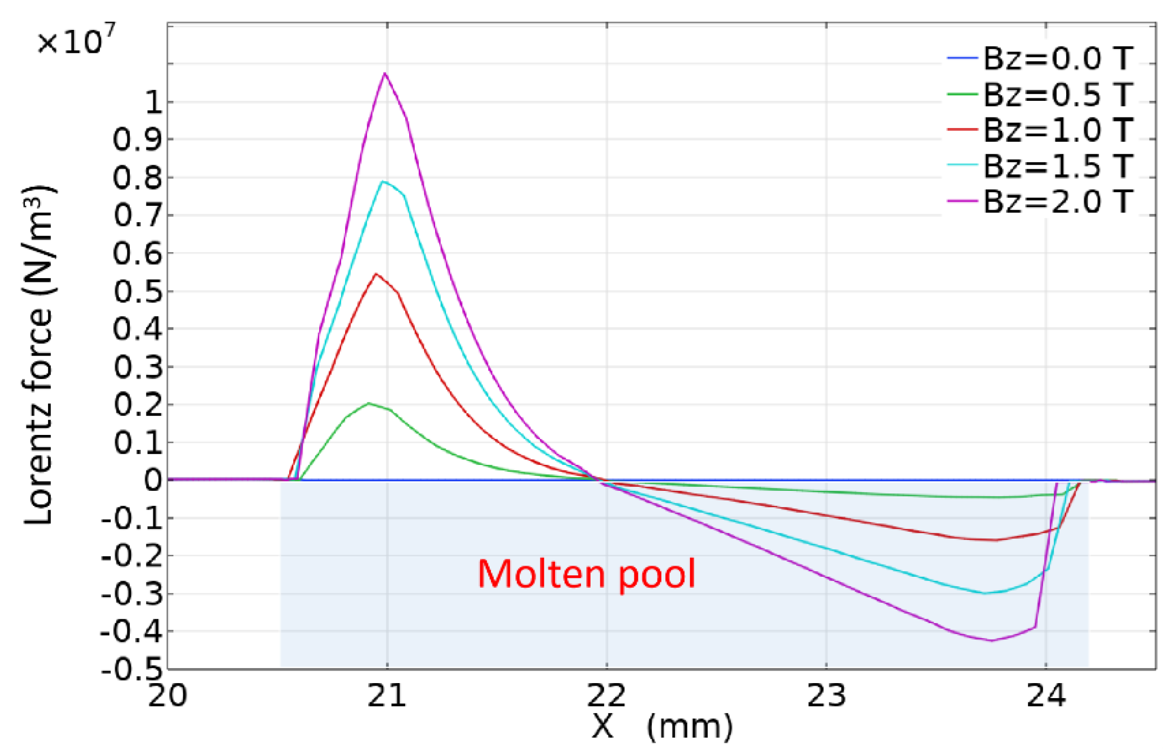
4.2.1. The Effect of the Magnetic Field on the Flow Field of the Molten Pool

Figure 5 shows the distribution of the free surface flow field of the molten pool under different magnetic field strengths. At Bz = 0 T, there is no Lorentz force in the molten pool, and the surface tension of the molten pool fluid gradually increases from the center to the edge of the molten pool under the action of the surface tension gradient force, and the flow inside the molten pool is formed by the joint action of gravity and buoyancy to form natural convection. Therefore, the free surface flow velocity of the molten pool is greater than the internal velocity of the molten pool, which flows from the center to the edge and accumulates at the edge of the molten pool, and forms a typical double vortex state inside the molten pool. The Lorentz force in the lower part of the molten pool is smaller than that of the free surface of the molten pool, and the direction and surface tension gradient are approximately tangential to the direction of the circulation generated by the buoyancy coupling (shown in Figure 6). This reduces the convective strength of the melt pool, and the enhancement is more significant with the increase in the magnetic field strength. When a steady magnetic field is introduced into the laser melting, the convective characteristics of the molten pool remain almost the same as in the absence of a magnetic field, as shown in Figure 7a–e. As the magnetic flux density increases, the fluid velocity in the steady magnetic field inside the molten pool generates an induced current, which forms an induced Lorentz force in the direction opposite to the fluid direction at all times under the action of the steady magnetic field. Therefore, the molten pool flow velocity decreases with increasing magnetic flux density, as shown in Figure 5a–e, and the suppression effect is higher on the left side of the melt pool than on the right side. This is because the direction of the Lorentz force generated by the steady magnetic field is always opposite to the direction of the fluid velocity, and its magnitude is proportional to the square of the velocity. The greater the velocity, the greater the Lorentz force induced, and the more significant the inhibition of the molten pool flow velocity.

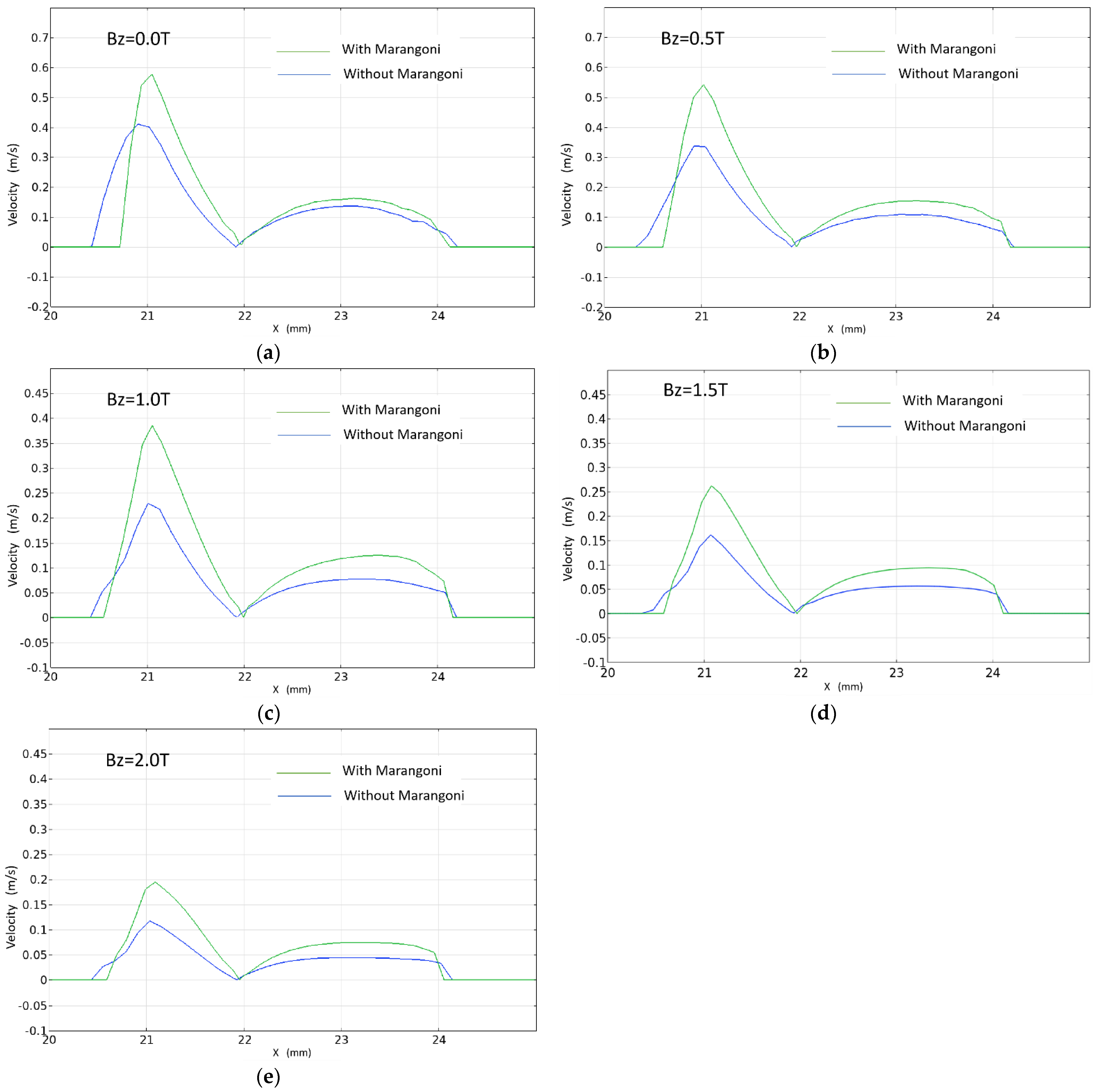
4.2.2. Influence of Marangoni Force on the Flow Field of Laser Melting Pool

The effect of the Marangoni force on the flow field for different magnetic fields is shown in Figure 8a–e. It can be seen that the Marangoni force on the flow field of the laser melting at the different magnetic fields is consistent, i.e., the flow velocity of the pool is higher than that without the Marangoni force when the Marangoni force is considered. This is because the direction of the Marangoni force is along the tangential direction of the free surface, which will increase the velocity of the molten pool under the action of the Marangoni force.

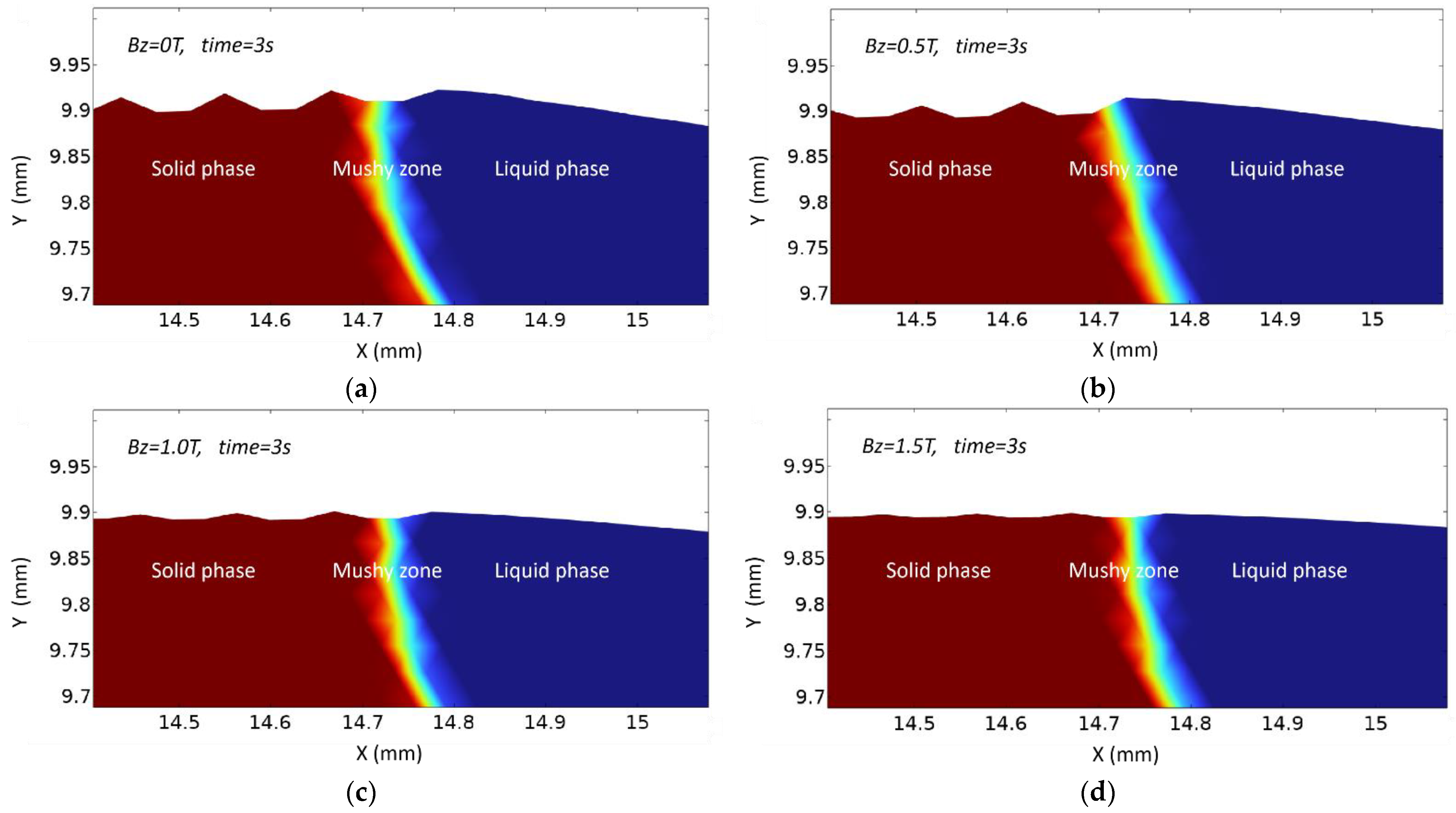
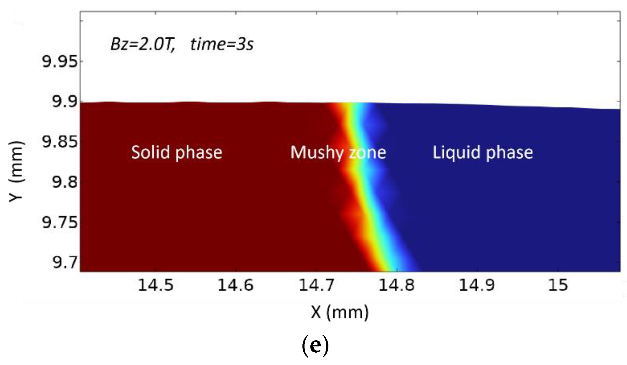
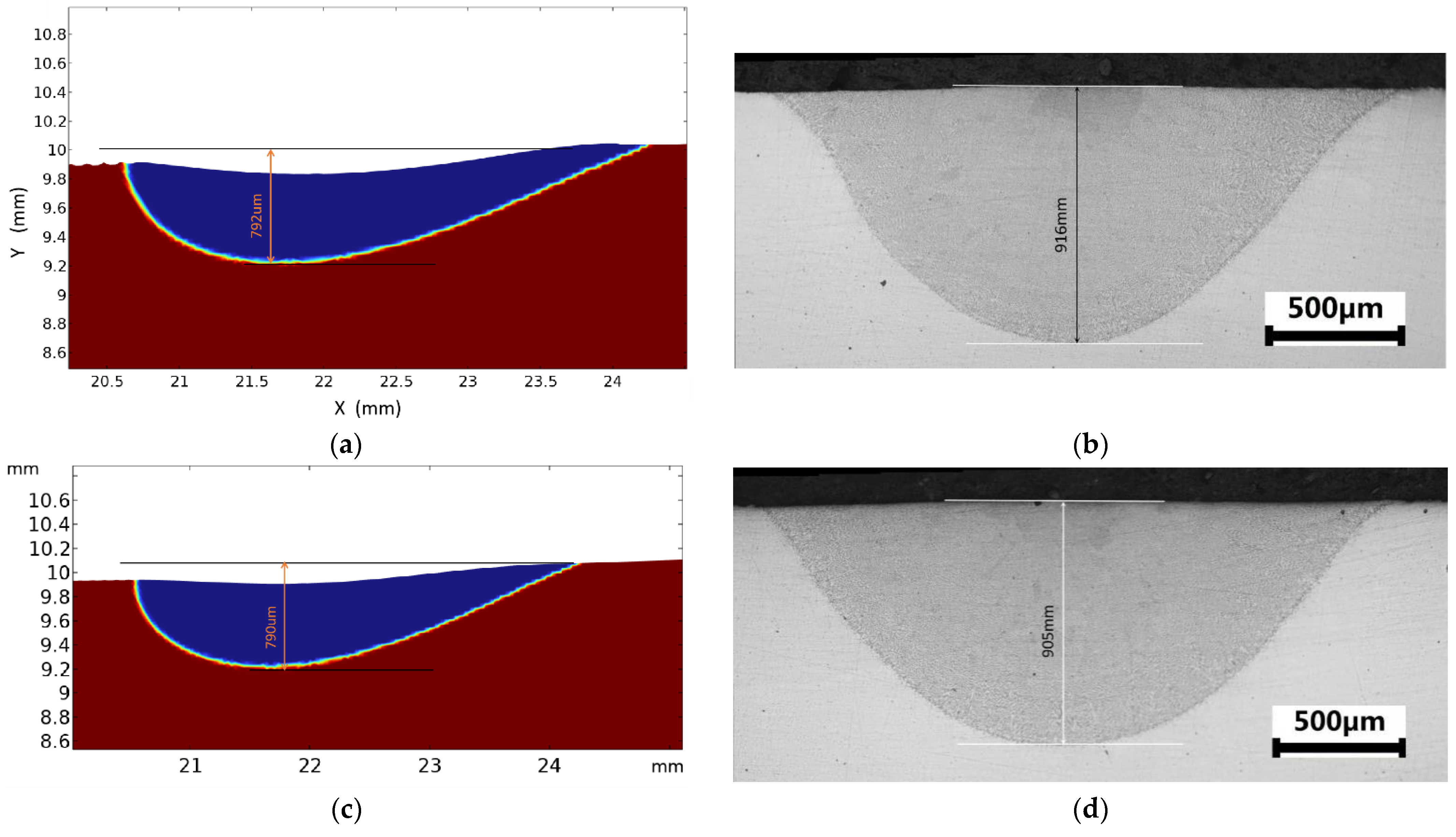
4.2.3. Effect of Magnetic Field Strength on the Shape of the Laser Melt Pool

In the laser heating process, fluctuations in the free surface velocity of the molten pool cause ripples to form on the surface during cooling. According to the molten pool free surface control equation, the deformation rate normal to the grid boundary is equal to the directional velocity direction of the flow rate, so the simulation can explain the ripples on the surface of the molten condensation layer.
In the absence of the magnetic field, the molten pool moves with the laser beam on the model surface during laser melting and redistributes the molten pool on the model surface under the capillary and thermal capillary forces (Marangoni forces). Figure 8 shows the evolution of the molten pool from t = 0.6 to 4.6 s. During the heating phase, the molten pool temperature gradually increases with time, and the flow velocity in the molten pool gradually increases. As shown in Figure 9a–e, the red arrows represent the direction of fluid flow, and the length of the red arrows represent the magnitude of fluid velocity. Marangoni vortices are caused by the thermal capillary force formed in the molten pool, transporting the hotter material from the center of the molten pool to the edge of the molten pool, resulting in a depression in the center of the molten pool due to material loss. After 4.5 s, the laser heat source disappears and the molten pool solidifies rapidly. As shown in Figure 9f, due to the lack of an external heat source, the internal surface tension of the melting pool rapidly decreases, the convection of the melting pool weakens, the surface ripple fluctuations disappear, and the surface shape of the melting pool flattens out.
The heating and cooling of laser fusion coagulation of an applied steady magnetic field are essentially the same as that with no applied magnetic field.
The solidification process of the molten pool under different steady magnetic field strengths is shown in Figure 10. The right region is liquid, the left region is solid, and the middle paste region is a mixture of liquid and solid states. As the molten pool moves from the left side to the right side, the thermal capillary force of the molten pool dominates the fluid flow. According to the evolution mechanism study of the molten pool morphology [31], the dominant forces in the molten pool are the capillary and thermal capillary forces. These two forces determine the surface morphology of the molten pool. When the surface morphology of the molten pool has a large curvature, the capillary force generates a normal force to reduce the surface tension and achieve a smooth surface profile and filling effect. Moreover, as the molten pool develops, the capillary force loses its dominant role in the region of less surface curvature and continues to form a smooth morphology in the tangential direction. To obtain a clear picture of the molten pool flow direction during cooling, the region close to solidification was chosen when a slight liquid flow did not affect the final molten pool morphology. Since the surface tension temperature coefficient of the material is negative, the thermal capillary forces within the molten pool are inversely proportional to the temperature, resulting in fluid flow from the low-surface-tension to the high-surface-tension side of the molten pool. In the liquid-phase region, as the magnetic field strength increases, the bulk force generated by the magnetic field increases (see Figure 11) in the direction opposite to the flow direction (Figure 7a–e). Consequently, the magnetic field force hinders the flow of the fluid from the center of the molten pool to the edge. The higher the magnetic field strength, the smaller the height difference between the center and the edge of the molten pool, and the smoother the molten pool. The magnetic field force causes the normal flow field to the surface layer at the edge of the molten pool to decrease, resulting in a corresponding decrease in the height of the ripple bump on the surface of the solidification layer. As the laser heat source moves away, the melt pool rapidly reaches the solid temperature, and the bumps with small curvature on the free surface of the molten pool are not smoothed out in time, so the morphology is retained. When the magnetic flux density increases from 0 T to 2.0 T, the ripples on the surface of the solidification layer are gradually suppressed.

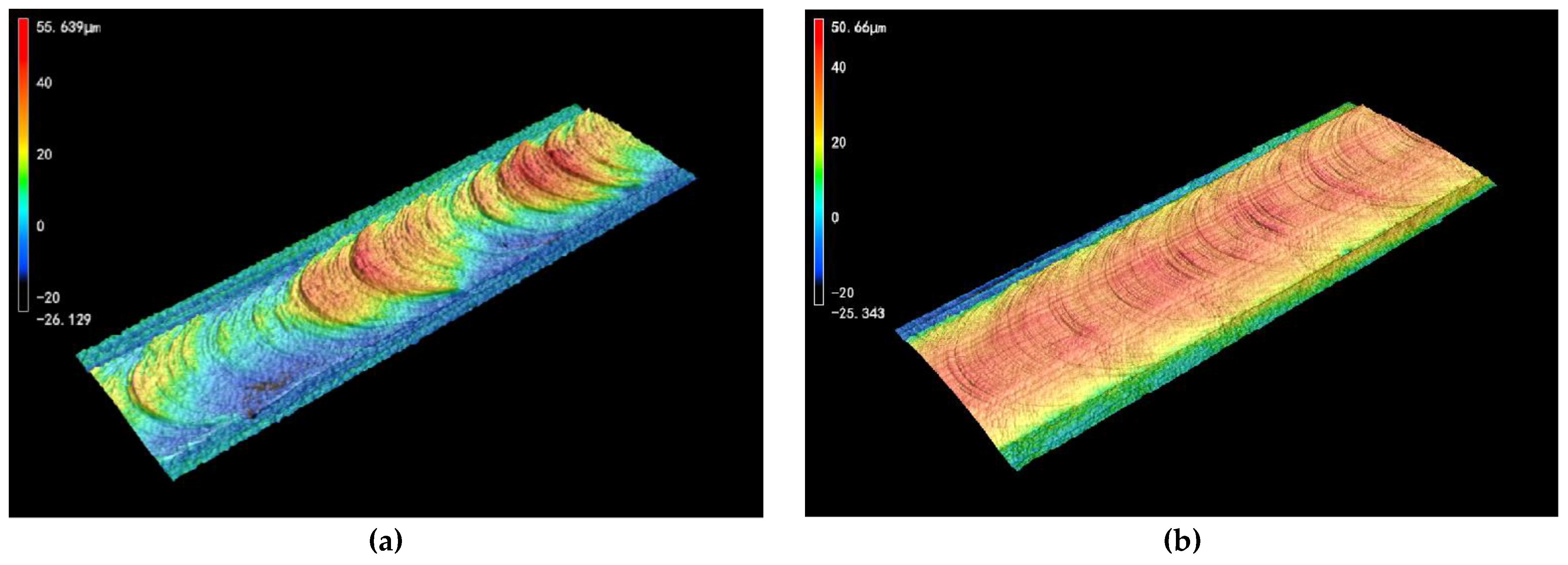
5. Experimental Verification

We conducted a detailed analysis of transient melting dynamics and the evolution of the molten pool morphology based on the steady magnetic field to better understand the laser melting mechanism. Moreover, to further verify the numerical model’s accuracy, the same calculation parameters, such as the initial geometry (ideal smooth surface), laser power (P = 1500 W), and top-hat distribution of beam intensity and boundary, were used. In addition, a laser heat source with a velocity of 4 mm/s was defined and moved from left to right along the melting surface. Figure 10 demonstrates the evolution of the transient molten pool morphology by moving heat source radiation, and the solidified morphology of the melting surface and cross-sections were measured using a scanning electron microscope. At 2.5 s, the molten pool was completely stable. The position (4.5 s) was selected as the final shape of the molten pool, as shown in Figure 12a. When Bz = 0 T, the simulated molten pool depth was 792 μm, and the actual molten pool depth was 916 μm (Figure 12b). Compared with the actual size, the difference in value was 13.5%. When Bz = 2 T, the simulated molten pool depth was 790 μm, and the actual molten pool depth was 905 μm (Figure 12d). Compared with the actual size, the difference in value was 12.7%. Comparing the data in Figure 12b,d, we can see that when Bz = 2 T is applied, the magnetic field has less influence on the melting depth.
According to the surface topography shown in Figure 13a,b, the surface ripples of the molten pool fluctuate greatly in the absence of a magnetic field, while the surface ripples are suppressed when the magnetic flux density is 2 T. This is consistent with the simulation results.
It is shown that the model has a certain reliability from the above two aspects.

6. Conclusions

In this study, a 2D transient laser melting mathematical model was developed based on the solid–liquid unified model by considering the solid–liquid phase change, heat transfer and fluid flow, capillary and Marangoni forces, gravity, thermal buoyancy, and Lorentz force inside the laser melting pool, and simulating the solid–liquid phase change, fluid flow, and heat transfer under the action of a steady magnetic field using finite element COMSOL Multiphysics.
With the assistance of a steady magnetic field, a directional Lorentz force was generated inside the melt pool at all times in the opposite direction of the melt pool flow, which resulted in a significant suppression of the melt pool convection. The suppression effect was more pronounced as the magnetic induction strength increased. However, the effect of the steady magnetic field on the temperature was not significant, and the maximum temperature of the melt pool surface was 2174 K after applying a steady magnetic field with a magnetic induction of 1 T, which is only 64 K higher than that in the state without a magnetic field. On the one hand, the effect of the steady-state magnetic field on the melt depth was smaller, and the melt depth was 916 μm after the application of the steady-state magnetic field with the magnetic induction of 2 T, which is only 11 μm less than that without the magnetic field.
The numerical model’s accuracy was verified by the experiments. The actual molten pool depth was 916 μm. The simulated molten pool depth was 792 μm. Compared with the actual size, the difference was 13.5%.
The free surface fluctuation of the molten pool was suppressed when the steady magnetic field was applied, making the surface morphology of the molten pool solidification layer flat. Moreover, without changing the original laser coagulation process parameters, the steady magnetic field controlled the surface morphology of the coagulation layer.

Author Contributions

Writing–original draft: S.X.; Validation: K.J.; Writing–review and editing: L.W.; Resources: J.Y. All authors have read and agreed to the published version of the manuscript.

Funding

This research was funded by the State Key Program of National Nature Science of China (Grant 52035014) and Key R&D Program of Zhejing (2023C01054).

Institutional Review Board Statement

Not applicable.

Informed Consent Statement

Informed consent was obtained from all subjects involved in the study.

Data Availability Statement

Not applicable.

Conflicts of Interest

The authors declare no conflict of interest.

References

  1. Zhang, Q.; Wang, L.; Mei, X.; Yao, J. Development of laser surface modification technology. Strateg. Study Chin. Acad. Eng. 2020, 22, 71–77. [Google Scholar] [CrossRef]
  2. Kac, S.; Kusinski, J. SEM structure and properties of ASP2060 steel after laser melting. Surf. Coat. Technol. 2004, 180–181, 611–615. [Google Scholar] [CrossRef]
  3. Qi, K.; Yang, Y.; Hu, G.; Lu, X.; Li, J. Thermal expansion control of composite coatings on 42CrMo by laser cladding. Surf. Coat. Technol. 2020, 397, 125983. [Google Scholar] [CrossRef]
  4. Tang, Z.J.; Liu, W.W.; Zhang, N.; Wang, Y.W.; Zhang, H.C. Real-time prediction of penetration depths of laser surface melting based on coaxial visual monitoring. Opt. Lasers Eng. 2020, 128, 106034. [Google Scholar] [CrossRef]
  5. Xia, Z.; Fang, F.; Ahearne, E.; Tao, M. Advances in polishing of optical freeform surfaces: A review. J. Mater. Process. Technol. 2020, 286, 116828. [Google Scholar] [CrossRef]
  6. Li, J.; Liu, Y.; Zhou, Y.; Shi, W.; Zhang, M. Effect of laser remelting on quality and mechanical properties of selective laser melting of TC4. Laser Optoelectron. Prog. 2022, 59, 0514006. [Google Scholar] [CrossRef]
  7. Mohajerani, S.; Bordatche, V.E.; Tutunea-Fatan, O.R. Recentd evelopments in modeling of laser polishing of metallic materials. Lasers Manuf. Mater. Process. 2018, 5, 395–429. [Google Scholar] [CrossRef]
  8. De Moraes, D.A.; Czekanski, A. Parametric Thermal FE Analysis on the Laser Power Input and Powder Effective Thermal Conductivity during Selective Laser Melting of SS304L. J. Manuf. Mater. Process. 2018, 2, 47. [Google Scholar] [CrossRef] [Green Version]
  9. Zheng, Y.; Cao, L.; Wang, J.; Xie, J.; Chen, J.; Wang, D.; Wang, S.; Xu, J.; Lu, H. Surface morphology refinement and Laves phase control of plasma arc additively manufactured Inconel 718 via an alternating magnetic field. Mater. Des. 2022, 223, 111161. [Google Scholar] [CrossRef]
  10. Yao, Z.Z.; Zhang, C.Q.; Song, Q.W.; Lu, X.J.; Kong, J.Q.; Yao, J.H. Ultrasonic assisted laser repair of V-grooves in nickel-based superalloy. J. Zhejiang Univ. (Eng. Sci.) 2021, 55, 887–895. [Google Scholar] [CrossRef]
  11. Shuai, S.; Lin, X.; Xiao, W.; Yu, J.; Wang, J.; Ren, Z. Effect of Transverse Static Magnetic Field on Microstructure of Al-12%Si Alloys Fabricated by Powder-BlowAdditive Manufacturing. Acta Metal. Sin. 2018, 54, 918–926. [Google Scholar] [CrossRef]
  12. Wang, C.; Liu, H.; Zhou, R.; Jiang, Y.; Zhang, X. Characteristic behaviors of particle phases in NiCrBSi-TiC composite coating by laser cladding assisted by mechanical vibration. Acta Metal. Sin. 2013, 49, 221–228. [Google Scholar] [CrossRef]
  13. Liang, L.; Pang, S.; Shao, X.; Wang, C.; Jiang, P. In situ weak magnetic-assisted thermal stress field reduction effect in laser welding. Metal. Mater. Trans. A 2017, 49, 198–209. [Google Scholar] [CrossRef]
  14. Gatzen, M. Influence of low-frequency magnetic fields during laser beam welding of aluminium with filler wire. Phys. Procedia 2012, 39, 56–66. [Google Scholar] [CrossRef] [Green Version]
  15. Markl, M.; Körner, C. Multiscale modeling of powder bed-based additive manufacturing. Annu. Rev. Mater. Res. 2016, 46, 93–123. [Google Scholar] [CrossRef]
  16. Ebrahimi, A.; Kleijn, C.R.; Richardson, I.M. A simulation-based approach to characterise melt-pool oscillations during gas tungsten arc welding. Int. J. Heat Mass Transf. 2021, 164, 120535. [Google Scholar] [CrossRef]
  17. Tamanna, N.; Crouch, R.; Naher, S. Progress in numerical simulation of the laser cladding process. Opt. Lasers Eng. 2019, 122, 151–163. [Google Scholar] [CrossRef]
  18. Liu, H.X.; Cai, C.X.; Jiang, Y.H.; Zhang, X.W.; Wang, C.Q. Influence of alternatice magnetic field on macro morphology and microstructure of laser cladding Fe-based composite coating. Opt. Precis. Eng. 2012, 20, 2402–2410. [Google Scholar] [CrossRef]
  19. Wang, W.; Liu, Q.; Yang, G.; Qin, L.; Xiong, X. Numerical simulation of electromagnetic flow, temperature field and flow fieldin laser molten pool with elecromagnetic stirring. Chin. J. Lasers 2015, 42, 0202007. [Google Scholar] [CrossRef]
  20. Wang, J.; Ge, H.; Xu, H.; Zhang, Q.; Yao, J. Effect of induced lorentz force on Fe element distribution in laser cladding inconel 718 coatings. Rare Met. Mater. Eng. 2021, 50, 2799–2806. [Google Scholar]
  21. Yu, Q.; Wan, Q. Laser additive manufacturing of Ni45 alloys assisted by electromagnetic stirring. Chin. J. Lasers 2018, 45, 0402003. [Google Scholar] [CrossRef]
  22. Hu, Y.; Chen, Z.; Wang, L.; Yao, J. Numerical simulation of the steady magnetic field regulation of the laser molten pool heat transfer and flow behavior. Appl. Laser. 2014, 34, 508–512. [Google Scholar] [CrossRef]
  23. Wang, L.; Hu, Y.; Lin, Y.; Li, J.; Yao, J. Distribution gradient control of laser melting injection reinforcement particles by electromaginetic compund field. Chin. J. Lasers 2018, 45, 1002001. [Google Scholar] [CrossRef]
  24. Zhao, Z.; Zeng, J.; Lai, Z.; Yin, J.; Guo, T. Laser polishing die steel assisted by steady magnetic field. Micromachines 2022, 13, 1493. [Google Scholar] [CrossRef] [PubMed]
  25. Gruzd, S.A.; Lomaev, S.L.; Simakov, N.N.; Gordeev, G.A.; Bychkov, A.S.; Gapeev, A.A.; Cherepetskaya, E.B.; Krivilyov, M.D.; Ivanov, I.A. Analysis of the Effect of Magnetic Field on Solidification of Stainless Steel in Laser Surface Processing and Additive Manufacturing. Metals 2022, 12, 1540. [Google Scholar] [CrossRef]
  26. Bachmann, M.; Avilov, V.; Gumenyuk, A.; Rethmeier, M. Experimental and numerical investigation of an electromagnetic weld pool support system for high power laser beam welding of austenitic stainless steel. J. Mater. Process. Technol. 2014, 214, 578–591. [Google Scholar] [CrossRef]
  27. Meng, X.; Artinov, A.; Bachmann, M.; Rethmeier, M. Numerical and experimental investigation of thermo-fluid flow and element transport in electromagnetic stirring enhanced wire feed laser beam welding. Int. J. Heat Mass Transf. 2019, 144, 118663. [Google Scholar] [CrossRef]
  28. Zhang, C.; Zhou, J.; Shen, H. Role of capillary and thermocapillary forces in laser polishing of metals. J. Manuf. Sci. Eng. 2017, 139, 041019. [Google Scholar] [CrossRef]
  29. He, X.; Elmer, J.; DebRoy, T. Heat transfer and fluid flow in laser microwelding. J. Appl. Phys. 2005, 97, 084909. [Google Scholar] [CrossRef]
  30. Shen, H.; Pan, Y.; Zhou, J.; Yao, Z. Forming Mechanism of Bump Shape in Pulsed Laser melting of Stainless Steel. J. Heat Transfer. 2017, 139, 062301. [Google Scholar] [CrossRef]
  31. Perry, T.L.; Werschmoeller, D.; Duffie, N.A.; Li, X.; Pfefferkorn, F.E. Examination of selective pulsed laser micropolishing on microfabricated nickel samples using spatial frequency analysis. J. Manuf. Sci. Eng. 2009, 131, 021002. [Google Scholar] [CrossRef]
Figure 1. Geometry model of the molten pool.
Metals 13 00720 g001
Figure 2. Schematic of experimental equipment for laser melting on 316L stainless steel.
Metals 13 00720 g002
Figure 3. Temperature field distribution in the molten layer (B = 0 T, t = 4.5 s).
Metals 13 00720 g003
Figure 4. Temperature field distribution on the melting surface at different magnetic flux densities (t = 4.5 s).
Metals 13 00720 g004
Figure 5. Distribution of flow field at different magnetic field strengths (t = 4.5 s). (a) Bz = 0 T; (b) Bz = 0.5 T; (c) Bz = 1 T; (d) Bz = 1.5 T; and (e) Bz = 2 T.
Metals 13 00720 g005
Figure 6. Coupling mechanism of steady-state magnetic field and molten pool.
Metals 13 00720 g006
Figure 7. Magnitude of Lorentz force at different magnetic field strengths (t = 4.5 s). (a) Bz = 0.0 T; (b) Bz = 0.5 T; (c) Bz = 1.0 T; (d) Bz = 1.5 T; and (e) Bz = 2.0 T.
Metals 13 00720 g007
Figure 8. Effect of Marangoni force on the flow field at different magnetic field strengths (t = 4.5 s). (a) Bz = 0.0 T; (b) Bz = 0.5 T; (c) Bz = 1.0 T; (d) Bz = 1.5 T; and (e) Bz = 2.0 T.
Metals 13 00720 g008
Figure 9. Evolution of laser remelting pool. (a) t = 0.7 s; (b) t = 0.9 s; (c) t = 2 s; (d) t = 3 s (e) t = 4.5 s; and (f) t = 4.6 s.
Metals 13 00720 g009
Figure 10. Evolution of solidification surface topography under different magnetic fields. (a) Bz = 0.0 T; (b) Bz = 0.5 T; (c) Bz = 1.0 T; (d) Bz = 1.5 T; and (e) Bz = 2.0 T.
Metals 13 00720 g010aMetals 13 00720 g010b
Figure 11. Lorenz force distribution at different magnetic fields (t = 4.5 s).
Metals 13 00720 g011
Figure 12. Shape of the molten pool (a) at 4.5 s Bz = 0 T, (b) actual molten pool shape Bz = 0, (c) at 4.5 s Bz = 2.0 T, and (d) actual molten pool shape Bz = 2 T.
Metals 13 00720 g012
Figure 13. Three-dimensional surface morphology. (a) Bz = 0 T; (b) Bz = 2.0 T.
Metals 13 00720 g013
Table 1. Boundary conditions.
PhysicsBoundary ConditionsBoundaryPhysical Condition
Heat transferBoundary heat source5Laser irradiation
Convection1, 2, 3, 4, 5, 6, 7Natural convection
Diffuse surface5Radiation
Fluid flowTangential stress5Marangoni effect
Normal stress5Weak contribution
Lorentz forceDomain 1, Domain 2Magnetic field
Wall1, 2, 3, 6, 7No-slip wall
Table 2. Physical properties of 316L stainless steel [30].
PropertySymbolValue
Liquidus temperature (K)Tl1723
Solidus temperature (K)Ts1673
Melting temperature (K)Tm1698
Liquid phase density (kg/m3)ρl6350
Solid phase density (kg/m3)ρs7980
Thermal conductivity of liquid phase (W/(m∙K))kl40
Thermal conductivity of solid phase (W/(m∙K))ks50
Specific heat of liquid phase (J/(kg∙K))Cpl746
Specific heat of solid phase (J/(kg∙K))Cps464
Constant in surface tension gradient (N/(m∙K))Aγ2.8 × 10−4
Latent heat of fusion (J/kg)Lf2.47 × 105
Surface tension of pure metal (N/m)γm1.588
Thermal expansion coefficient (1/K)β1.1 × 10−5
Convective coefficient (W/(m2∙K))h10
Emissivity ε0.5
Table 3. Chemical composition (wt%) of 316L stainless steel.
CSiMnPSNiCrMoFe
0.020.551.55<0.03<0.0310.016.52.08Bal.
Disclaimer/Publisher’s Note: The statements, opinions and data contained in all publications are solely those of the individual author(s) and contributor(s) and not of MDPI and/or the editor(s). MDPI and/or the editor(s) disclaim responsibility for any injury to people or property resulting from any ideas, methods, instructions or products referred to in the content.

