Article

Influence of the Alloying Elements on the Corrosion Behavior of As-Cast Magnesium–Gallium–Zinc Alloys in Simulated Body Fluid

by
Anabel A. Hernández-Cortés
,
José C. Escobedo-Bocardo
* and
Dora A. Cortés-Hernández
Center for Research and Advanced Studies of the National Polytechnic Institute (CINVESTAV), Av. Industria Metalúrgica No.1062, Parque Industrial Saltillo-Ramos Arizpe, Ramos Arizpe CP25900, Coahuila, Mexico
*
Author to whom correspondence should be addressed.
Metals 2023, 13(4), 743; https://doi.org/10.3390/met13040743
Submission received: 23 February 2023 / Revised: 30 March 2023 / Accepted: 4 April 2023 / Published: 11 April 2023
(This article belongs to the Section Biobased and Biodegradable Metals)

Abstract

:
The in vitro corrosion rate of as-cast ternary Mg-Ga-Zn alloys in simulated body fluid (SBF) was evaluated. The effects of Ga3+ and Zn2+ on the formation, growth and stability of Ca, P-rich compounds on the surface of the ternary alloys, and the effect of these compounds on corrosion rate, were studied. Ternary Mg-Ga-Zn alloys (Ga from 0.375 to 1.5 wt% and Zn from 1.5 to 6 wt%) were obtained and then immersed in SBF to evaluate the corrosion rate using the weight loss method. The species formed on the alloys surface were characterized by X-ray diffraction (XRD), scanning electron microscopy (SEM) and Fourier-transform infrared spectroscopy (FT-IR). The formation of amorphous Ca, P-rich compounds on the alloys was observed. The species formed are related to the corrosion rate and the ions released into the SBF. The Mg, Ga and Zn ions released into the SBF during the corrosion process of the studied alloys play an important role in the growth of the Posner’s clusters, propitiating the reduction in size of the Ca, P-rich agglomerates. The corrosion rate of these as-cast ternary alloys increased as the intermetallics formed increased. The amount and size of the intermetallics formed depend on the Ga and Zn concentration in the alloys.

1. Introduction

The evolution of research in the field of biomaterials has led in recent years to the development of a novel concept known as biodegradable materials, which may eventually replace bioinert materials in some specific applications [1]. Implants manufactured with biodegradable materials support the damaged tissue while it regenerates. During this process, the implanted material gradually degrades, integrates and interacts with tissue in a way that mimics the physiological environment without causing adverse reactions or collateral damage [2]. Biodegradable metals are defined as metals that gradually corrode in vivo with an appropriate host response elicited by the release of corrosion products, which eventually dissolve completely, fulfilling their mission of assisting the tissue healing without leaving residues [3]. Magnesium and its alloys, pure iron and zinc are the materials that are currently being evaluated as possible candidates to be adapted to this new generation of materials, since they have acceptable mechanical properties for load-bearing applications. In addition, the human body tolerates their corrosion products well. Among these materials, Mg has the mechanical properties closest to those of human bone [4,5]. Furthermore, magnesium and its alloys have been shown to be potentially biocompatible [6] and biodegradable due to their in situ degradation properties in the human body [7]. Although their degradation is desirable, finding an appropriate balance between the rate of implant degradation and the rate of tissue healing is an important subject of research. Several Mg alloys have been proposed to improve corrosion resistance and facilitate the metabolization of the corrosion products resulting from the degradation process in the biological environment. Another characteristic that makes magnesium an excellent candidate for use as a biodegradable biomaterial for osteosynthesis applications is its osteoconductive property. Magnesium-based implants promote increased bone mass formation and a higher rate of mineral deposition around the implant [8]. The technique known as biomimetic apatite coating, which consists of imitating bone mineralization by immersing the implants in a simulated body fluid (SBF) that mimics the inorganic composition, pH and temperature of human blood plasma [9], has been used for evaluating the bioactivity and degradation rate of magnesium and its alloys [10]. In this test, magnesium degradation leads to the formation of oxides, hydroxides, hydrogen gas, sulfates and different types of Mg/Ca phosphates or carbonates, and it has been shown that phosphates or carbonates may have a positive impact on biocompatibility. The formed layers may reduce the corrosion rate and may influence protein adsorption and cell binding to Mg by modifying the surface chemistry and morphology [11]. There are numerous reports indicating that magnesium promotes the precipitation of calcium phosphates in an in vitro environment, a characteristic that can be used to induce or improve osteoconductivity [12], since calcium phosphates have compositional resemblance to bone mineral and induce a biological response similar to that generated during bone remodeling [13]. Thus, magnesium and its alloys may improve biocompatibility of prostheses and promote bone remodeling at the implantation site [14]. It is difficult to specify the composition of the constituents that will form due to the reaction between magnesium alloys and SBF (in addition to MgO and/or Mg(OH)2), since the compounds formed vary with the SBF composition, the immersion parameters (pH, temperature and immersion time) and the composition of the alloy [15]. Depending on the experimental conditions, apart from apatite, numerous calcium carbonates and phosphates of variable chemical composition have been generally identified [16]. The released metallic cations from the magnesium alloys into the surrounding fluid may participate in the formation of oxides and hydroxides and may incorporate into the structure of calcium phosphates. Since Mg is the most abundant ion, its interaction with the products formed by biomimetic methods on the magnesium surface has been explored [17]. Magnesium ions inhibit apatite crystallization under different conditions [18], leading to the precipitation of amorphous calcium phosphate films or magnesium/calcium apatites ((Ca1-xMgx)10(PO4)6OH2) on the surface of metallic magnesium and magnesium alloys incubated in simulated physiological fluids [19]. These compounds have also been observed on magnesium-based devices implanted in vivo, so its presence may have a beneficial effect on the osteoconduction process [20].
Corrosion and passivation of Mg alloys are phenomena of electrochemical nature. Corrosion is the electrochemical dissolution of metallic Mg. Passivation may be caused by the formation of a protective surface film. The substrate alloy influences corrosion and passivation behavior by influencing the composition of the surface film [21]. It is expected that the reaction layer generates a transitory passivation, which may lead to the gradual degradation of the alloy, offering an initial barrier against corrosion. The initial total coverage of the surface by the coating and then the gradual dissolution of the film are keys to avoid a rapid evolution of hydrogen at the implant site as part of the cathodic reaction of the Mg alloy in the body fluid [21]. The nature of this layer of corrosion products not only influences the subsequent degradation process but can also affect the biological response of bone tissues to implants. Various alloying elements are incorporated into Mg to improve mechanical properties and/or corrosion resistance. Alloying elements influence the structure of the alloys and impact corrosion performance by modifying the surface morphology, corrosion resistance and corrosion products. The incorporation of Ga as an alloying element [22] improves the corrosion resistance of Mg-Ga alloys due, among other factors, to the incorporation of gallium hydroxide and/or oxide, which are products of the reaction of this ion with the surrounding medium, into the magnesium hydroxide layer. The incorporation of this ion as a result of the dissolution of the alloy may even be beneficial in the biological environment since gallium has shown therapeutic activity in bone metabolic disorders, such as hypercalcemia [23]. The formation of zinc phosphates from a phosphate bath on an AZ91D alloy has been studied and the incorporation of zinc ions, resulting from the dissolution of the alloy, into the reaction layer was observed [24]. In the initial phases, these zinc ions accelerate the hopeite nucleation, but the continuous reaction and growth of hopeite nuclei form a layer of insoluble calcium phosphates, which slows down the dissolution of the alloy, improving corrosion resistance. Some treatments have been used to improve functional and structural properties of the Mg-Zn binary alloys. The alloying through a pre-alloyed Mg-4.1Zn powder was used to simultaneously enhance the corrosion resistance and mechanical properties of AM (additive manufacturing) geometrically ordered Mg-Zn scaffolds [25]. On the other hand, in order to improve corrosion resistance and biocompatibility, B-type carbonate apatite (CAp) coatings were conformed on as-cast and T4-treated Mg-xZn (x = 1, 5 and 7 wt%) alloys containing Zn-rich second phases [26] Additionally, Mg-0Zn, Mg-20Zn and Mg-30Zn alloys, obtained by powder metallurgy, were developed in the aim of improving mechanical properties, wear performance and corrosion resistance [27]. When the ternary Mg-Ga-Zn alloy is subjected to degradation conditions in a pseudophysiological solution, the presence of Mg [18], Ga [28] and Zn [29] ions in the solution is expected. However, a deep investigation is required to elucidate the effect of these ions on the composition and stability of the layer of corrosion products and the evolution of this layer with immersion.
In a previous work, we studied the effect of the unidirectional and cross-rolling on the microstructure, corrosion rate and mechanical properties of Mg-0.375Ga and Mg-0.750Ga alloys [30]. In the present work, we analyzed the influence of the alloying elements of six as-cast ternary Mg-Ga-Zn alloys, released as ions into the surrounding SBF as a consequence of the corrosive process, on the characteristics of the reaction layer formed.

2. Materials and Methods

2.1. Alloys Manufacturing

Six ternary alloys were prepared from high-purity magnesium (Stanford Advanced Materials, Lake Forest, CA, USA, 99.99 wt %, Fe ≤ 2 ppm, Ni ≤ 6 ppm, Cu ≤ 2 ppm), gallium (Sigma-Aldrich, St. Louis, MO, USA, 99.99 wt. %, Ca ≤ 0.6 ppm, K ≤ 1.6 ppm, Mg ≤ 0.1 ppm, Mn ≤ 0.1 ppm, Mo ≤ 0.2 ppm) and zinc (Metalúrgica Lazcano, Ciudad de México, México, Fe ≤ 0.0010, Ni < 0.0002, Cu ≤ 0.0003). Metals were melted in a resistance furnace equipped with a graphite crucible and a stirrer of the same material for homogenization of the molten alloy under an Ar-1%SF6 protective atmosphere. Inductively coupled plasma atomic emission spectroscopy (ICP-OES Perkin Elmer, Waltham, MA, USA, model Optima 8300) was used to determine the chemical composition of the alloys. The matrix and second phases were characterized using optical microscopy (Olympus Vanox, Breiningsville, PA, USA AHMT3) and scanning electron microscopy (SEM, Philips, Houston, TX, USA, XL30 ESEM) equipped with energy-dispersive X-ray spectroscopy (EDS). To observe the microstructure, specimens were prepared metallographically. Initially, specimens were ground (SiC grind papers, from 600 to 1200 grit size), then polished (1 and 3 μm diamond pastes) and finally etched. Etching was carried out using acetic-glycol and acetic-picral reagents. The chemical composition and grain size of the obtained alloys are shown in Table 1. Alloys are identified according to their nominal percentages of Ga and Zn. Grain size was measured using the average grain intercept (AGI) method. This method consists of the drawing line segments (randomly positioned) on the micrograph. Then, grain size is calculated using the following equation:
grain   size = line   length number   of   intersections

2.2. Evaluation of Corrosion and Bioactivity

To evaluate the corrosion rate and bioactivity of the alloys, the method proposed by Kokubo [31] was selected, using a simulated body fluid (SBF K-9) as the immersion medium. This solution has a composition and ionic concentration similar to that of human blood plasma, as shown in Table 2.
As-cast alloy specimens (1 × 1 × 0.3 cm3) were obtained and their surface was ground (SiC papers, from 600 to 1200 grit size). An ultrasonic bath and acetone were used to clean specimens for a period of 15 min. Each dried specimen was weighed (Ohaus analytical balance, 0,0001 g of accuracy, Ohaus de México S.A. de C.V., México City, México) and immersed in 30 mL of SBF contained in a plastic flask. Flasks were kept at 37 ± 0.5 °C (Fisher Scientific incubator, 637D, Fisher Scientific Mexicana, Monterrey, México) for different periods of time (7, 14, 21 and 28 days). Experiments were duplicated, using one sample for the in vitro bioactivity assessment and other for the corrosion rate evaluation.
The weight loss method (G1 ASTM standard [32]) was used to evaluate corrosion rate. After each immersion period, specimens were removed from the SBF and immersed for 15 min in an aqueous solution (200 g/L of CrO3, 10 g/L of AgNO3 and 20 g/L of Ba(NO3)2) [33] to remove the corrosion products. Specimens were cleaned with alcohol using an ultrasonic bath for 15 min. To evaluate the corrosion rate, specimens were weighed and Equation (2) was used [32]:
corrosion   rate = 8.76 × 10 4   W A T D
where:
T = exposure time (h);
A = specimen area (cm2);
W = mass loss (g);
D = density (g/cm3).
The Archimedes principle was used to evaluate density. The surface of the corroded specimens was analyzed by SEM-EDS.
To identify corrosion products and the phases formed after immersion in SBF, thin-film X-ray diffraction, within the range of 10° and 80° in the 2θ position, was performed (Bruker, D8 Advance). Fourier transform infrared spectroscopy (FTIR, Fisher Scientific, Nicolet iS5) was used as a complementary technique.
The remaining SBFs were analyzed by inductively coupled plasma–atomic emission spectroscopy (ICP-OES, Perkin Elmer, Optima 8300). Additionally, the change in pH of SBF with immersion time was recorded (Fisher Scientific, Orion Star A211, Fisher Scientific Mexicana, Monterrey, México).

3. Results and Discussion

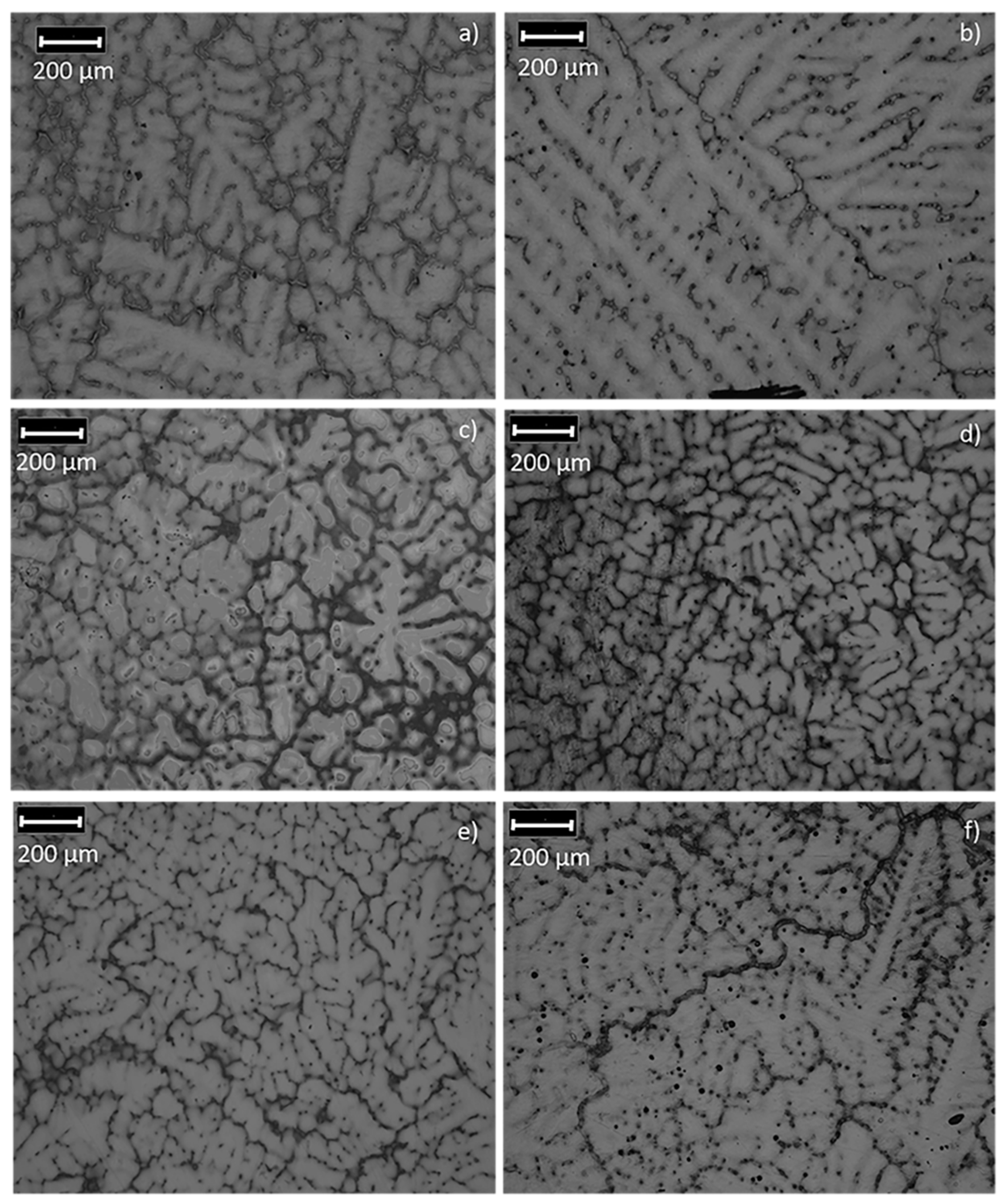
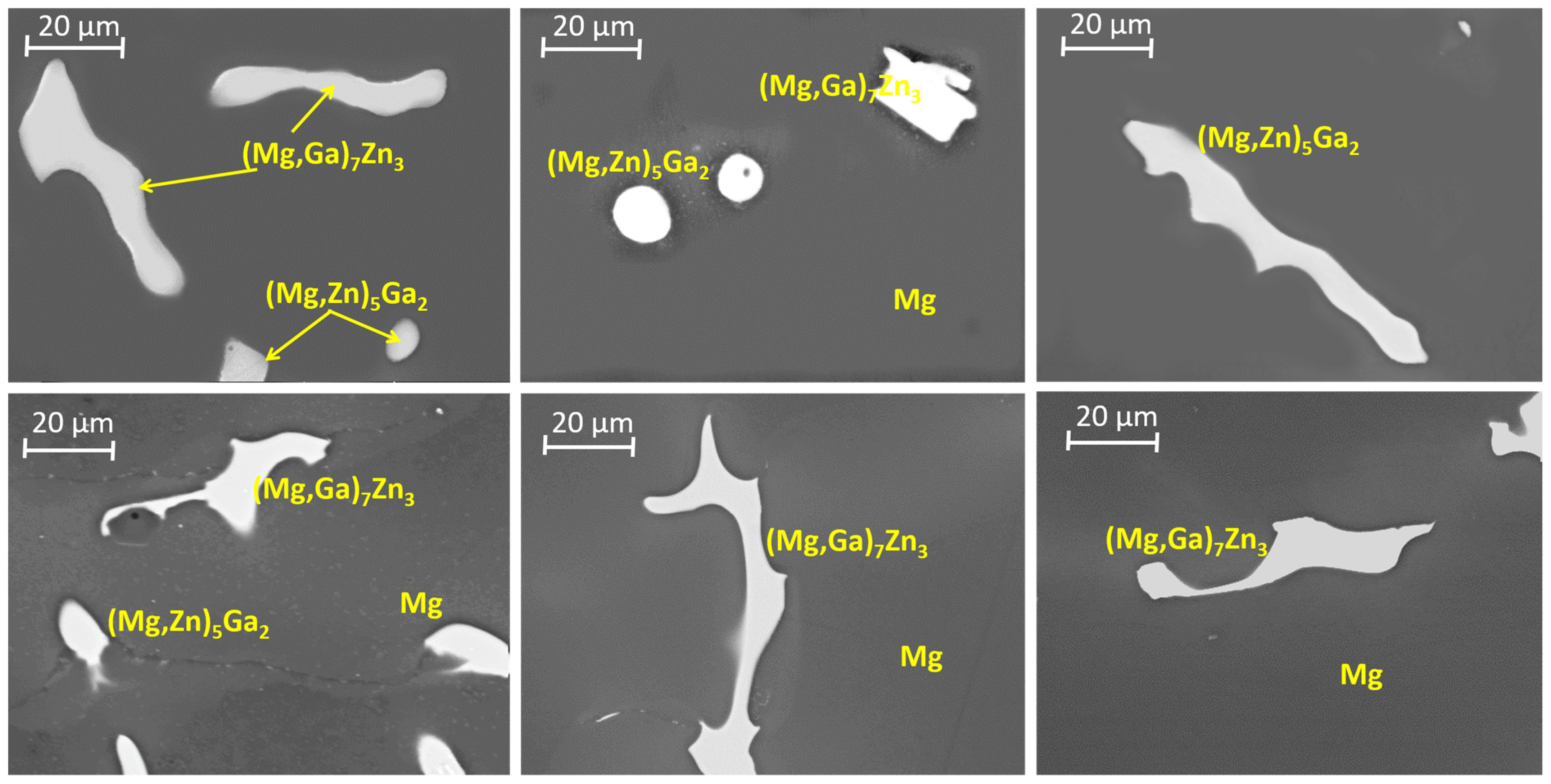
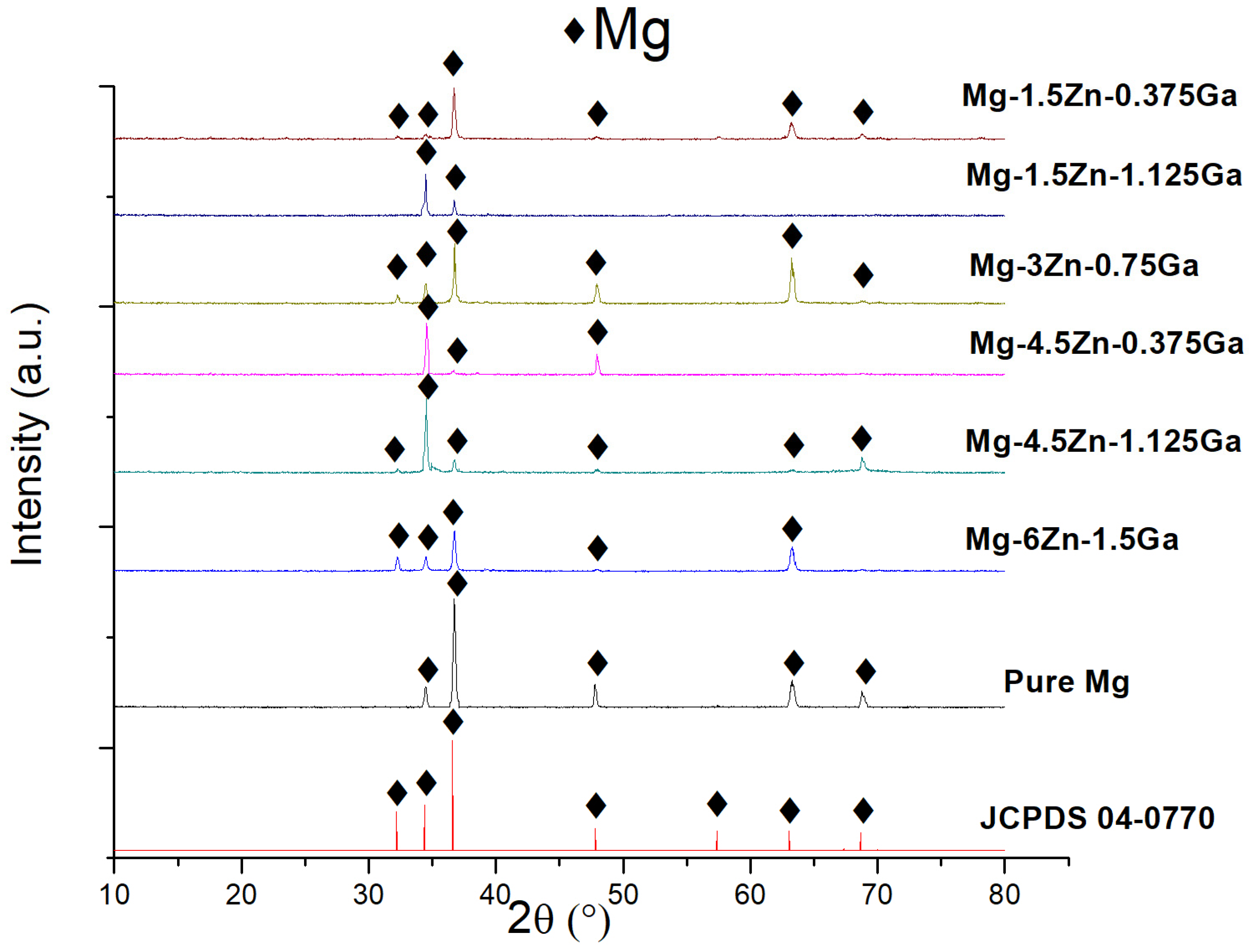
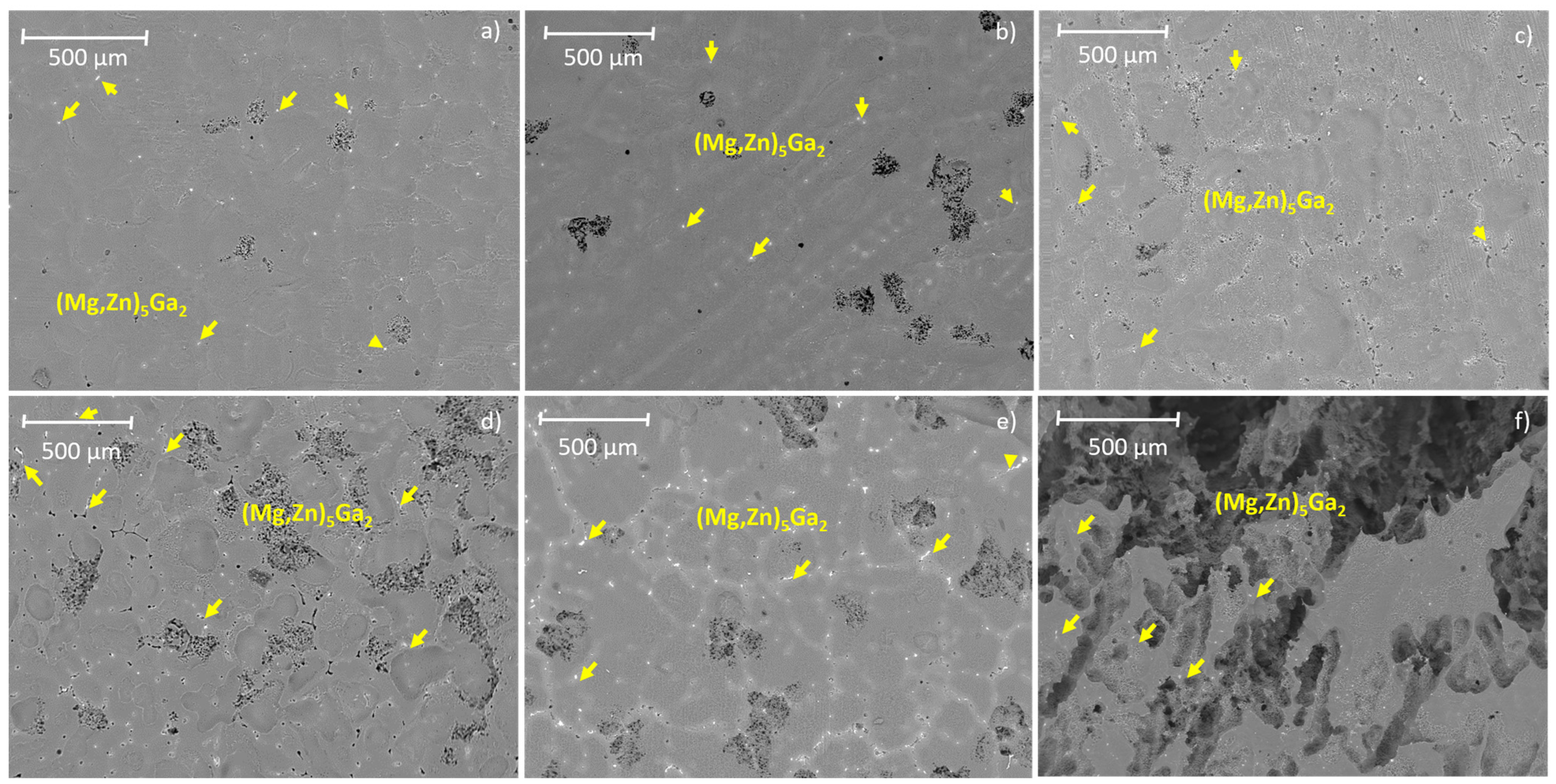
3.1. Microstructural Analysis

Figure 1 shows the microstructure of the as-cast ternary alloys. A dendritic microstructure with precipitates, mainly at the interdendritic regions and grain boundaries, can be observed. The amount of precipitates depends on the concentration of alloying elements. As can be seen in Figure 1, grain size decreased due to the addition of alloying elements. Figure 2 shows SEM images of the intermetallics found in the α-Mg matrix of the analyzed alloys. The ternary Mg-Ga-Zn phase diagram has not yet been reported. Taking into account the binary Mg-Ga [34] and Mg-Zn [35] phase diagrams and the Ga and Zn content in the alloys, the predicted binary intermetallics are Mg5Ga2 and Mg7Zn3. The EDS elemental analysis of the intermetallics observed by SEM indicated the formation of ternary intermetallics. According to the values of the semiquantitative elemental composition, the intermetallics formed may be (Mg,Ga)7Zn3 and (Mg, Zn)5Ga2.
Figure 3 shows the XRD patterns of the ternary alloys before immersion in SBF. A single phase corresponding to α-magnesium (JCPDS 04-0770) was detected. It was not possible to detect binary or ternary intermetallics with this technique.

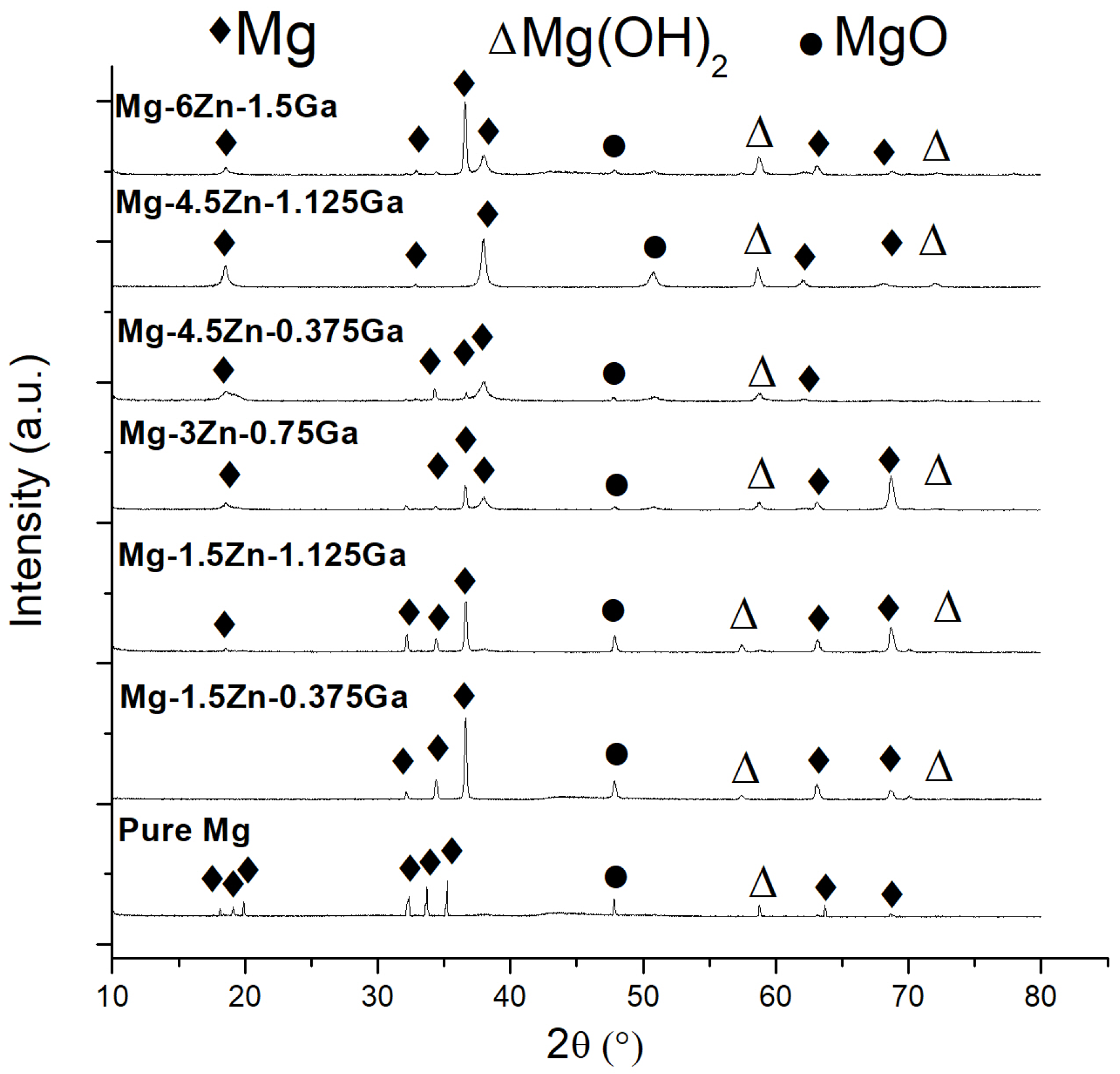
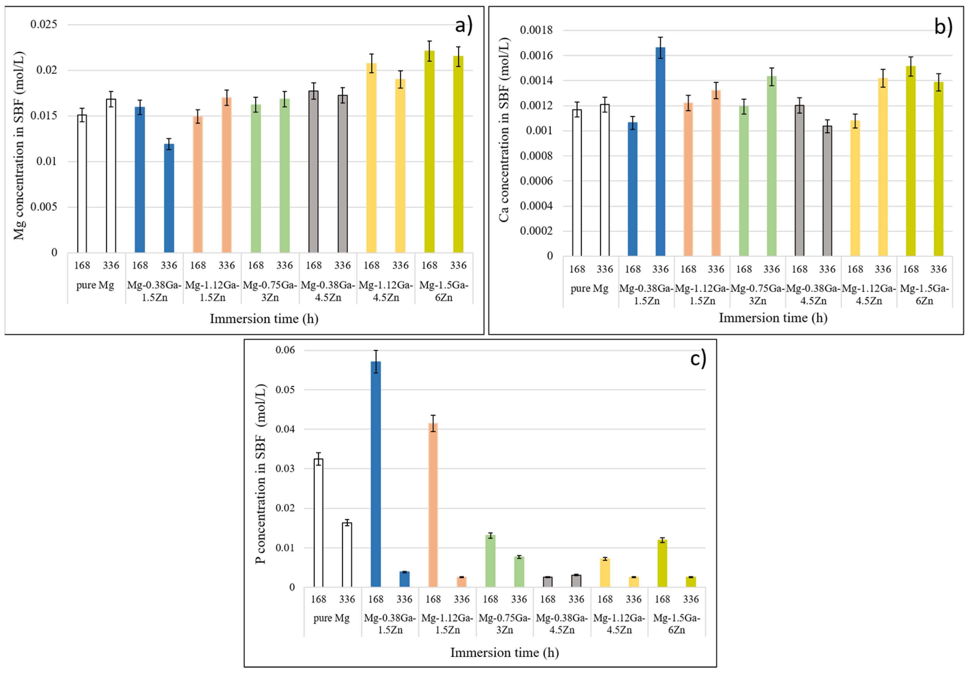
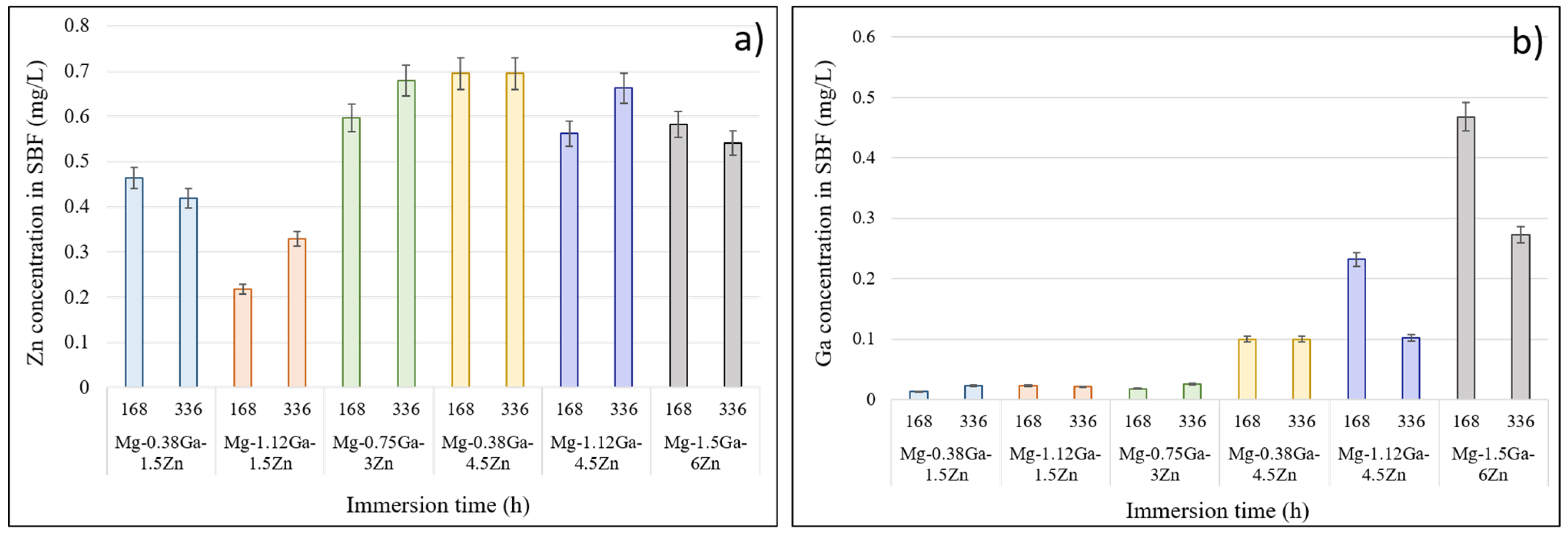
3.2. Degradation of the Mg-Ga-Zn Alloys in SBF

In general (Figure 4a,b), ternary alloys show the formation of a layer of reaction products. This layer presents interconnected cracks formed due to the contraction that this layer undergoes during drying, and some structures in the form of protruding mounds are observed (yellow arrows, Figure 4a). These mounds are observed in greater detail in Figure 4b (yellow circles), which were identified as hydrogen blisters. Hydrogen atoms produced as a result of the cathodic reaction [36] can permeate corrosion products, accumulate within the matrix and react with the matrix to form hydrides. Since hydrides are incompatible with the matrix, some hydrogen atoms will combine to produce hydrogen gas at the hydrides-matrix interface, which will lead to the build-up of local high pressure, leading to the formation of blisters on the matrix [37]. The presence of localized blisters on the alloys after removing corrosion products (purple circles, Figure 4c) is evidence of a type of localized corrosion.
Figure 5 shows the diffraction patterns of the ternary alloys after 168 h of immersion in the SBF. These XRD patterns indicate that the main components are α-magnesium, magnesium hydroxide and magnesium oxide. This layer is mainly constituted of Mg(OH)2, which has a Pilling/Bedworth ratio of 1.77, which reduces the possibility of fracture due to internal lateral tensile stresses; however, compression stresses persist [38]. The conjunction of these stresses and the fact that the corroded layer formed by the presence of the MgO/Mg(OH)2 alternate layers [39] promotes a tendency to basal cleavage [40], producing the observed cracking.
The corroded surface of the ternary alloys, after removing corrosion products, is shown in Figure 6. All the alloys show localized corrosion, and the corrosion behavior is clear: corrosion increases as the amount of precipitates is increased. In the Mg-0.38Ga-1.5Zn alloy (Figure 6a), few and shallow pits are observed; in subsequent images (Figure 6b–f), the number of pits and their depth increase. The yellow arrows point to the (Mg, Zn)5Ga2 intermetallic.
Figure 7 shows the morphology of the corroded surface of the Mg-0.75Ga-3Zn alloy, where a preferential type of corrosion is clearly observed (Figure 7a). The degradation occurs preferentially in the magnesium matrix, which is denoted by areas of low relief formed by corrosion and detachment of corroded material. The high-relief zones correspond to the interdendritic regions where the second-phase precipitates are located. Figure 7b (magnification of the area framed in yellow in Figure 7a) shows that the areas adjacent to the second-phase precipitates are the areas where corrosion preferentially occurs. This characteristic allowed us to determine the type of corrosion that occurs in ternary Mg-Zn-Ga alloys, identifying this type as micro-galvanic corrosion. This phenomenon occurs due to the effect of the corrosion potential difference between magnesium and second phases, since magnesium has a lower standard reduction potential [41] than those corresponding to Zn and Ga. All the alloys studied showed this morphology and type of corrosion.

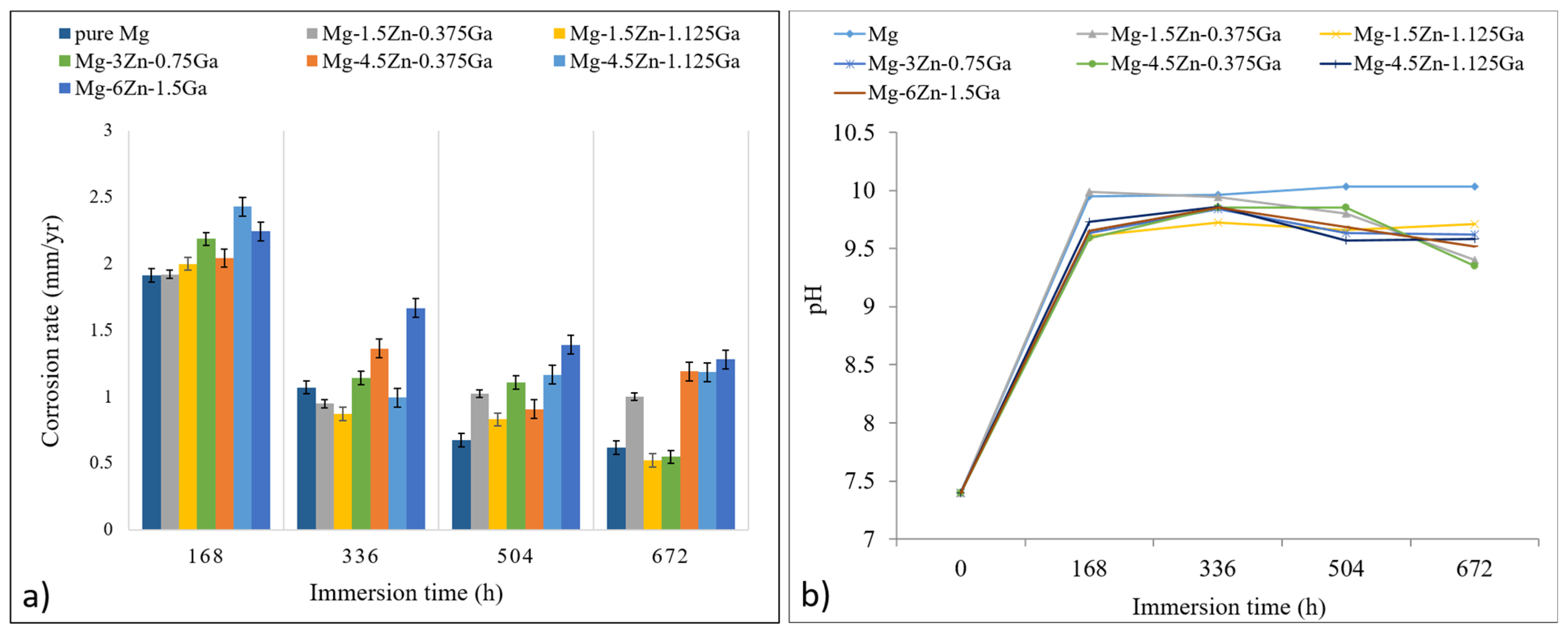
3.3. Degradation Rate Measurement

The calculated corrosion rate for the as-cast ternary alloys and the as-cast pure magnesium is shown in Figure 8a. In general, corrosion rate of the alloys is higher in the initial evaluation period (168 h, pH = 7). In this stage, the anodic reaction is favored (Equation (3)) since magnesium forms a galvanic coupling with the Ga, Zn-rich second phases. In this electrolytic cell, magnesium is less noble than zinc and gallium, which leads to the matrix dissolution, releasing mainly Mg, but also Ga and Zn (alloying elements in solid solution in the matrix) into the metal/aqueous medium interface. The release of these metal ions at the interface will eventually change the surface potential to positive values and the anodic polarization will increase. However, corrosion may continue since a stable protective reaction layer has not yet been formed on the alloy.
Anodic reaction: MM n+ + ne
Cathodic reaction: 2H2O + 2e → H2(g) + 2OH
Simultaneously, the cathodic reaction occurs in the fluid (Equation (4)) [36] and, as a result, hydroxyl ions are formed on the metal surface, which will eventually react with the metallic ions. This reaction will depend largely on the hydrogen overpotential. Since the overpotential of Mg and Zn are low, ion exchange reactions occur, leading to the formation of the species indicated in reactions 5 [36] and 6 [29]. Gallium has a high hydrogen overpotential, and the rate of reaction 7 [42] may eventually decrease, favoring reactions 5 and 6. Nonetheless, reactions 3 and 4 are still taking place but in a selective manner, since Ga(OH)3 is thermodynamically more stable.
Mg2+ + 2OH → Mg(OH)2
2Zn2+ + 4OH → 2Zn(OH)2
Ga3+ + 3OH → Ga(OH)3
After the formation of this partially protective hydroxide film on the metal surface, the corrosion rate is controlled by the diffusion of ions through the reaction layer; thus, corrosion rate will eventually decrease (Figure 8a, period from 336 to 504 h). Since there is no stirring nor heating of the fluid that may accelerate diffusion, as the immersion period increases, the diffusion and accumulation of species, such as Cl at the reaction layer, promote an increase in conductivity, propitiating the anodic depolarization due to the formation of hydroxides, causing the corrosion reaction to reactivate. The dissolution of the Mg and Zn hydroxides layer (Mg(OH)2 and Zn(OH)2) occurs according to Equations (8) and (9). The destabilization, fracture and detachment of this partially protective layer are assisted by the H2 evolution from the layer as it opens the way for fluid migration towards the partially protected metallic substrate. Due to tensile stresses and the high solubility of MgCl2, the protective layer can be detached and/or dissolved, exposing the metal surface to corrosion. This corrosion reaction 4 produces hydroxyl ions, which are added to those contributed by the occurrence of reactions 8 [28] and 9 [29], leading to an increase in pH and alkalization of the medium. Values of pH > 7, such as those measured in the SBF at immersion times >168 h (Figure 8b), allow the undetached or undissolved species from the substrate (Mg(OH)2, 6Zn(OH)2 and Ga(OH)3) to be more stable, offering an effective barrier against corrosion in these places, as can be seen in Figure 8a at 672 h of immersion. In the case of magnesium alloys for bone replacement applications, a thorough investigation needs to be performed under dynamic conditions.
Mg(OH)2 + 2 Cl → MgCl2 + 2 OH
6Zn(OH)2 + Zn2+ + 2Cl → 6Zn(OH)2 · ZnCl2
The corrosion rate of high-purity Mg is considered a reference to compare the corrosion rate of Mg alloys. One of the lowest corrosion rates calculated for Mg 99.9 is 0.25 ± 0.07 mm/year in a 3.5 wt.% NaCl solution saturated with Mg(OH)2 [43]. The average corrosion rate for magnesium after 28 d (720 h) under the conditions used in the present work was 0.617 mm/year (Figure 8a). Two-sample t-tests were used to compare the mean corrosion rates (after 28 d) of the alloy samples to determine whether they are significantly different (Minitab 18, α = 0.05). It was found that the alloys with Zn content greater than or equal to 4.5 wt.% have the highest corrosion rate independently of the Ga amount. The corrosion rate for the alloy samples with Zn content lower than 3 wt.% is low, but a negative interaction between the Ga and Zn contents is present when the Ga content is lower than 0.75 wt.%. The corrosion rate for the Mg-1.5Zn-1.25Ga and Mg-3Zn-0.75Ga alloys is not statistically different from that of pure Mg. These results confirm that the corrosion rate increases as the content of alloying elements is increased, which is due to the higher amount of the intermetallics formed in the alloys. Nonetheless, as it can be seen in Figure 8, the corrosion rate was quantitatively evaluated as a function of the alloy composition. These intermetallics promote a galvanic coupling with the matrix, accelerating its degradation. The increase in alkalinity also leads to the saturation of the aqueous medium with Ca2+ and HPO42− ions as part of a pre-calcification process, which, according to reaction 10, promotes the deposition of a calcium phosphate layer on the unremoved reaction layer, which also contributes to its stability since these species are insoluble, making this layer a more effective barrier against corrosion.
Ca 2 + + HPO 4 2 + 2 H 2 O   CaHPO 4     2 H 2 O
Another reaction product that may contribute to the formation of a more efficient protective layer is the Mg3(PO4)2 insoluble compound, which is formed according to reaction 11.
Mg(H2PO4)2 + 4H2O→Mg3(PO4)2 · 4H2O + 4H3PO4

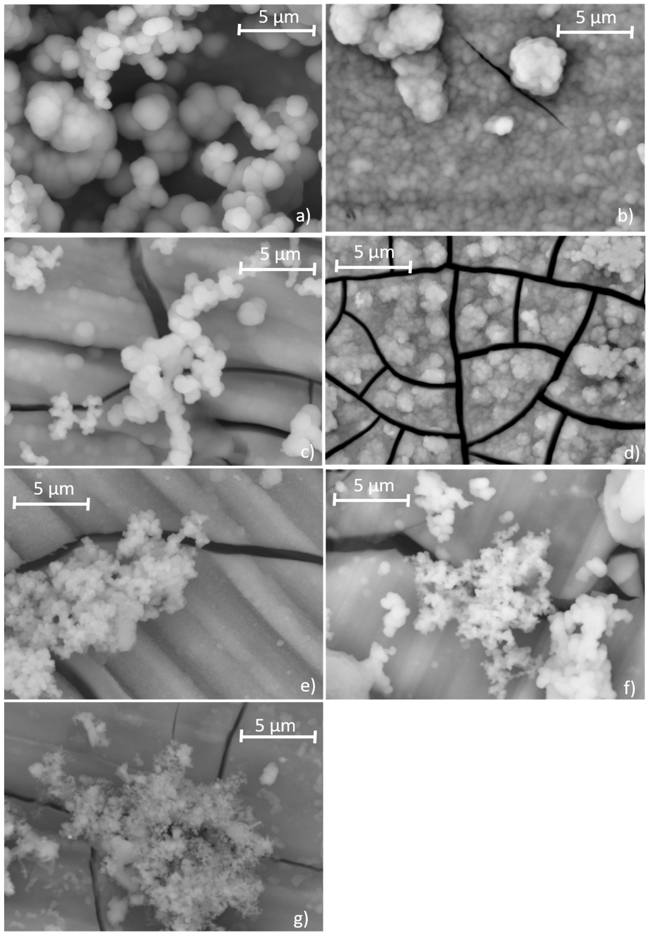
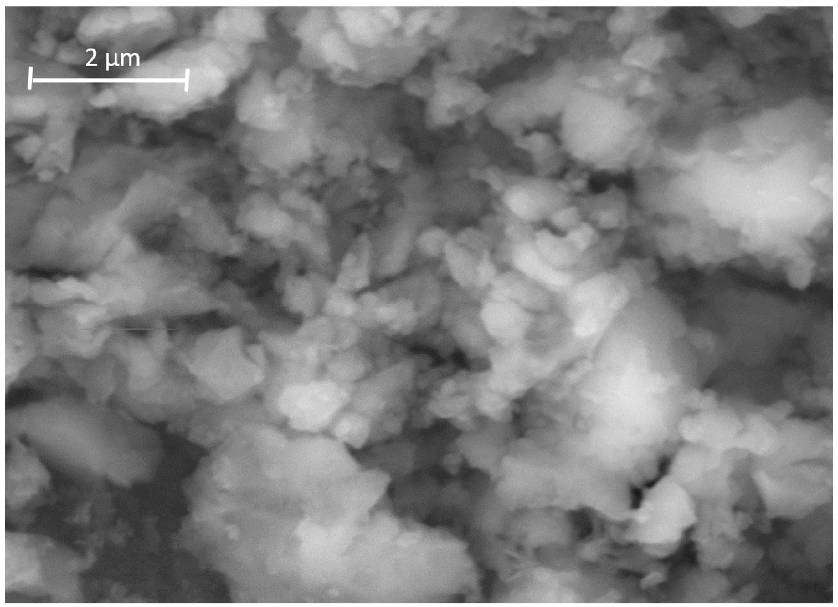
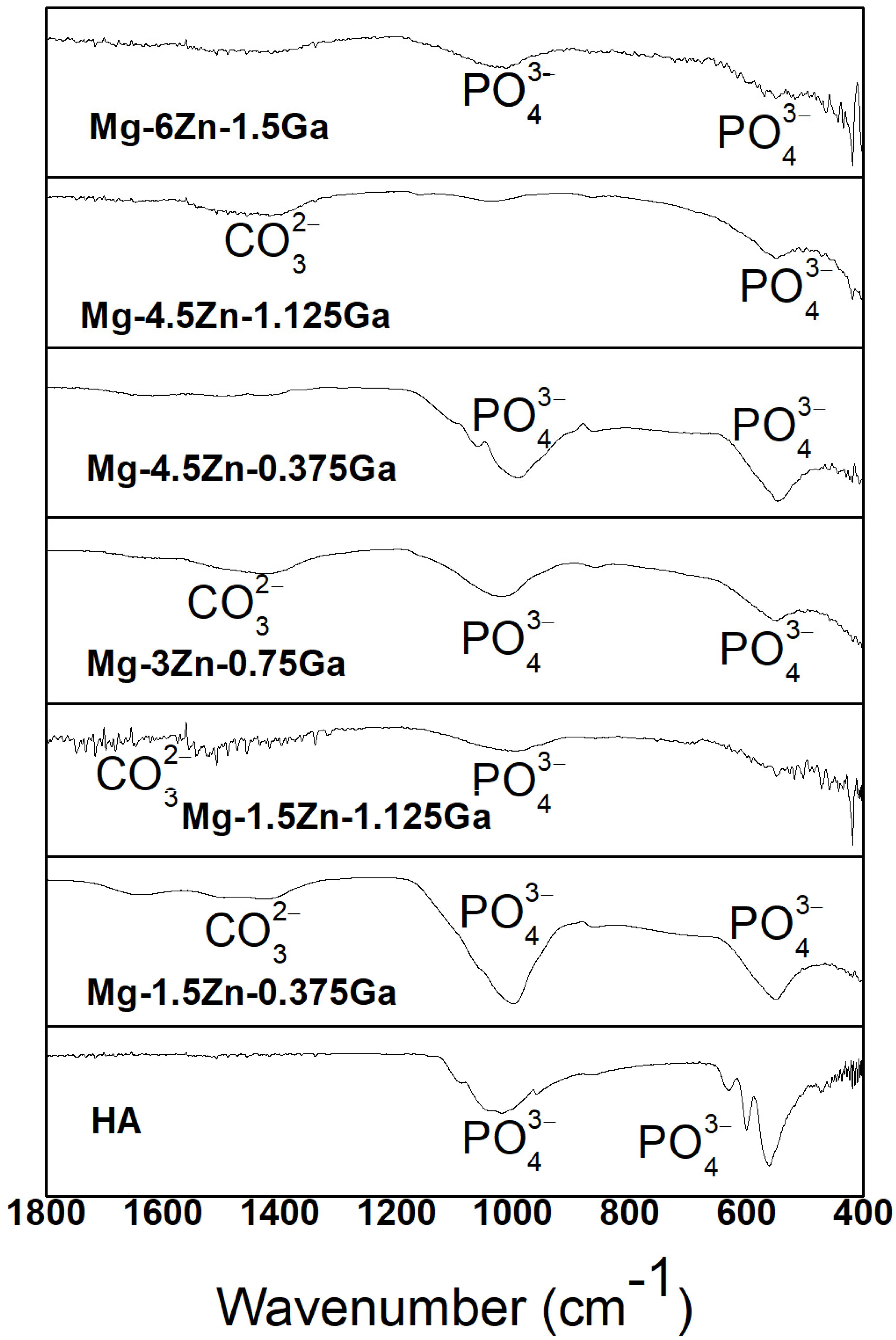
3.4. Formation of Ca−P Coatings on the Alloys Surface

Figure 9 and Figure 10 show the ionic concentrations of Mg, Ca, P, Zn and Ga in the remaining SBFs after 168 and 336 h of immersion. The Mg, Ca and P elements are constituents of the SBF. Variations in the ionic concentration of Mg are the result of the alloy degradation process (corrosion) and the formation/dissolution of Mg-rich compounds. Variations in the ionic concentration of Ca and P are the result of the formation/dissolution process of Ca, P-rich compounds. The presence of Zn and Ga ions in the SBF confirms the degradation of the alloys. As it can be observed, the ionic concentration of Zn and Ga increases as a function of the content of these elements in the alloy. The ionic concentration of these elements in SBF is low compared to that of magnesium, since corrosion occurs mainly in the αMg matrix where Zn and Ga are found in low concentrations (solid solution).
The corrosion products formed on the reaction surface of the as-cast ternary alloys after different immersion periods in SBF were identified by the EDS technique. Ca, P-rich compounds were also found (Figure 11); Ca/P ratios are shown in Table 3. These compounds have spherical morphologies of different sizes depending on the alloy composition. It is observed that on the alloys with a higher content of alloying elements, particles are finer than those observed on the alloys with a lower content of alloying elements. These particles have similar morphology and Ca/P ratio to those corresponding to precursor apatite spheres [44].
It has been widely discussed [10,14,15] that the saturation of the aqueous medium (SBF) with Ca2+, PO3−, Mg2+, OH and HPO42− ions, among others, leads to the formation and precipitation of calcium phosphates on the reaction surface of the magnesium alloys. The difference observed in the sphere size on the reaction surface may be associated with the substitution of Ca2+ by Mg2+, which promotes nucleation instead of growth of the apatite species formed. Kibalczyc [45] studied the effect of magnesium ions on the precipitation of calcium phosphates and determined that these ions mainly inhibit the formation of the amorphous calcium phosphate (ACP) and the growth of octacalcium phosphate (OCP). Gallium’s influence on the calcium phosphates’ formation was studied by Donnelly et al. [46], showing that gallium chloride in solution, at concentrations of 10–100 µM, inhibits the growth of hydroxyapatite seeds in metastable calcium phosphate solutions; the suggested mechanism indicates that gallium adsorbs on the seeds’ surface, inhibiting the crystal growth. The formation of ACPs on a substrate in SBF at 37 °C is proposed to be made from small clusters of ions known as Posner’s clusters (Ca9(PO4)6), which form within the fluid [47], followed by the densification and formation of massive ACP aggregates [48]. Although the role of Mg and Ga ions in the growth process of these clusters has not been clarified, it is thought that they act by substituting calcium ions into the structure, decreasing growth. Thus, an increase in the corrosion rate supposes an increase in the quantity of ions of the alloying elements (Mg, Ga and Zn) in the solution and, therefore, a higher substitution, which leads to the reduction in the size of the spheres in the agglomerates, as observed on the Mg-1.12Ga-4.5Zn and Mg-1.5Ga-6Zn alloys (Figure 11f,g). On the contrary, in the pure magnesium sample, which shows less degradation (Figure 8a), spheres are bigger.
The zinc ions that evolve from the alloy surface towards the SBF may eventually form insoluble zinc phosphates according to reaction 12 [24], possibly contributing to the mineralization of the phosphate layer on the alloy. Although no significant compositional changes were observed in the Ca, P-rich aggregates of the studied alloys, in the reaction surface of the Mg-1.5Ga-6Zn alloy, analyzed after 168 h of immersion in SBF, a morphological change in these agglomerates was observed (Figure 12).
3Zn2+ + 2H2PO4 + 4H2O + 4e→Zn3(PO4)2.4H2O + 2H2
The FTIR spectra corresponding to the surface of the as-cast ternary alloys after 7 days of immersion in SBF are shown in Figure 13. For all the alloys, as for the synthetic hydroxyapatite (HA), the absorption bands for the PO43− group were mainly observed (at 560, 600, 630 and 1020 cm−1), which indicates the nature of the formed compounds (calcium phosphates) on the samples after immersion in SBF. However, a broadening of the absorption bands is observed, which is indicative of the substitution of Ca ions by magnesium, gallium and zinc ions in the Ca, P-rich compounds formed. It was observed that this broadening becomes more pronounced as the amount of alloying elements in the alloy increases. This fact is related to the previously observed phenomenon that states that the higher the amount of alloying elements, the higher the corrosion/dissolution rate of the magnesium matrix, which, consequently, increases the quantity of ions dissolved into the aqueous medium. This increase in the amount of dissolved magnesium ions increases the possibility of substitution by these ions in the apatite structure. An absorption band located at 1452 cm−1 was also identified, which corresponds to the carbonate group (CO32−), found in amorphous calcium phosphates (observed at 1490–1425 cm−1 [49]).

4. Conclusions

The effect of the alloying elements on the corrosion mechanism that takes place when as-cast Mg-Ga-Zn ternary alloys (Ga from 0.375 to 1.5 wt% and Zn from 1.5 to 6 wt%) are immersed in simulated body fluid (SBF K-9) was evaluated. After immersion, a type of localized corrosion was identified on the surface of the alloys, which was typified as micro-galvanic corrosion. This process occurs due to the difference in potential between magnesium and second phases (Mg, Ga)7Zn3 and (Mg, Zn)5Ga2. Consequently, alloys with a higher quantity of second phases show a higher corrosion rate.
Corrosion promotes the formation of hydroxyl ions in the SBF, which leads to an increase in the pH of the medium. Under these conditions (pH > 10), the formation and stabilization of a layer containing Mg(OH)2, Zn(OH)2, Ga(OH)3 and other species promotes anodic polarization, reducing the corrosion reaction rate after 168 h of immersion. Under these conditions, the calcium phosphate nuclei formed may grow on the surface of the alloys. Corrosion of these alloys causes an increase in the concentration of Mg, Ga and Zn ions in the immediate vicinity of the reaction layer.
Morphology, Ca/P ratio and the presence of characteristic absorption bands in the corresponding FT-IR spectra indicate that the spherical aggregates and particles that formed on the reaction surface of the alloys after immersion in SBF are Ca, P-rich compounds. In these compounds, Ca has been partially substituted by Mg, Ga and Zn, while phosphate groups have been partially substituted by carbonate groups. This ionic substitution promotes a higher nucleation rate of Posner’s clusters, reducing growth, which leads to the reduction in the size of the Ca, P-rich agglomerates.

Author Contributions

Conceptualization, J.C.E.-B. and A.A.H.-C.; methodology, A.A.H.-C.; investigation, A.A.H.-C., J.C.E.-B. and D.A.C.-H.; resources, J.C.E.-B.; writing, A.A.H.-C., J.C.E.-B. and D.A.C.-H.; supervision, J.C.E.-B. and D.A.C.-H.; funding acquisition, J.C.E.-B. All authors have read and agreed to the published version of the manuscript.

Funding

This research was financed by CONACYT, México (Project ID: CB-201501: 257527).

Institutional Review Board Statement

Not applicable.

Informed Consent Statement

Not applicable.

Data Availability Statement

Data is unavailable due to privacy restrictions.

Conflicts of Interest

The authors declare no conflict of interest.

References

  1. Chandra, G.; Pandey, A. Preparation Strategies for Mg-Alloys for Biodegradable Orthopaedic Implants and Other Biomedical Applications: A Review. IRBM 2022, 43, 229–249. [Google Scholar] [CrossRef]
  2. Stanciu, L.; Diaz-Amaya, S. Biodegradable materials for medical applications. Introd. Biomater. 2022, 307–346. [Google Scholar] [CrossRef]
  3. Sezer, N.; Evis, Z.; Kayhan, S.M.; Tahmasebifar, A.; Koç, M. Review of magnesium-based biomaterials and their applications. J. Magnes. Alloy. 2018, 6, 23–43. [Google Scholar] [CrossRef]
  4. Ibrahim, H.; Esfahani, S.N.S.; Poorganji, B.; Dean, D.; Elahinia, M. Resorbable bone fixation alloys, forming, and post-fabrication treatments. Mater. Sci. Eng. C 2017, 70, 870–888. [Google Scholar] [CrossRef] [PubMed] [Green Version]
  5. Peuster, M.; Hesse, C.; Schloo, T.; Fink, C.; Beerbaum, P.; von Schnakenburg, C. Long-term biocompatibility of a corrodible peripheral iron stent in the porcine descending aorta. Biomaterials 2006, 27, 4955–4962. [Google Scholar] [CrossRef]
  6. Prakasam, M.; Locs, J.; Salma-Ancane, K.; Loca, D.; Largeteau, A.; Berzina-Cimdina, L. Biodegradable Materials and Metallic Implants—A Review. J. Funct. Biomater. 2017, 8, 4. [Google Scholar] [CrossRef] [Green Version]
  7. Zheng, Y.F.; Gu, X.N.; Witte, F. Biodegradable metals. Mater. Sci. Eng. R Reports 2014, 77, 1–34. [Google Scholar] [CrossRef]
  8. Uppal, G.; Thakur, A.; Chauhan, A.; Bala, S. Magnesium based implants for functional bone tissue regeneration—A review. J. Magnes. Alloy. 2022, 10, 356–386. [Google Scholar] [CrossRef]
  9. Wang, M.; Guo, L.; Sun, H. Manufacture of Biomaterials. In Encyclopedia of Biomedical Engineering; Narayan, R., Ed.; Elsevier: Oxford, UK, 2019; pp. 116–134. [Google Scholar]
  10. Xin, Y.; Hu, T.; Chu, P.K. In vitro studies of biomedical magnesium alloys in a simulated physiological environment: A review. Acta Biomater. 2011, 7, 1452–1459. [Google Scholar] [CrossRef]
  11. Grillo, C.A.; Alvarez, F.; Fernández Lorenzo de Mele, M.A. Degradation of bioabsorbable Mg-based alloys: Assessment of the effects of insoluble corrosion products and joint effects of alloying components on mammalian cells. Mater. Sci. Eng. C 2016, 58, 372–380. [Google Scholar] [CrossRef]
  12. Zhang, C.; Zeng, R.; Chen, R.; Liu, C.; Gao, J. Preparation of calcium phosphate coatings on Mg-1.0Ca alloy. Trans. Nonferr. Met. Soc. China 2010, 20, s655–s659. [Google Scholar] [CrossRef]
  13. Zhou, H.; Liang, B.; Jiang, H.; Deng, Z.; Yu, K. Magnesium-based biomaterials as emerging agents for bone repair and regeneration: From mechanism to application. J. Magnes. Alloy. 2021, 9, 779–804. [Google Scholar] [CrossRef]
  14. Keim, S.; Brunner, J.G.; Fabry, B.; Virtanen, S. Control of magnesium corrosion and biocompatibility with biomimetic coatings. J. Biomed. Mater. Res.—Part B Appl. Biomater. 2011, 96 B, 84–90. [Google Scholar] [CrossRef]
  15. Shin, K.; Acri, T.; Geary, S.; Salem, A.K. Biomimetic Mineralization of Biomaterials Using Simulated Body Fluids for Bone Tissue Engineering and Regenerative Medicine. Tissue Eng.—Part A 2017, 23, 1169–1180. [Google Scholar] [CrossRef] [PubMed]
  16. Habraken, W.; Habibovic, P.; Epple, M.; Bohner, M. Calcium phosphates in biomedical applications: Materials for the future? Mater. Today 2016, 19, 69–87. [Google Scholar] [CrossRef]
  17. Zreiqat, H.; Howlett, C.R.; Zannettino, A.; Evans, P.; Schulze-Tanzil, G.; Knabe, C.; Shakibaei, M. Mechanisms of magnesium-stimulated adhesion of osteoblastic cells to commonly used orthopaedic implants. J. Biomed. Mater. Res. 2002, 62, 175–184. [Google Scholar] [CrossRef] [PubMed]
  18. Wang, Y.; Wei, M.; Gao, J.; Hu, J.; Zhang, Y. Corrosion process of pure magnesium in simulated body fluid. Mater. Lett. 2008, 62, 2181–2184. [Google Scholar] [CrossRef]
  19. Kuwahara, H.; Al-Abdullat, Y.; Mazaki, N.; Tsutsumi, S.; Aizawa, T. Precipitation of Magnesium Apatite on Pure Magnesium Surface during Immersing in Hank´s Solution. Mater. Trans. 2001, 42, 1317–1321. [Google Scholar] [CrossRef] [Green Version]
  20. Liu, C.; Ren, Z.; Xu, Y.; Pang, S.; Zhao, X.; Zhao, Y. Biodegradable Magnesium Alloys Developed as Bone Repair Materials: A Review. Scanning 2018, 2018, 9216314. [Google Scholar] [CrossRef] [Green Version]
  21. Chen, X.B.; Birbilis, N.; Abbott, T.B. Review of Corrosion-Resistant Conversion Coatings for Magnesium and Its Alloys. Corrosion 2011, 67, 35005–35016. [Google Scholar] [CrossRef]
  22. Hernández-Cortés, A.A.; Escobedo-Bocardo, J.C.; Cortés-Hernández, D.A.; Almanza-Robles, J.M. Effect of gallium content and heat treatment on the microstructure and corrosion rate of magnesium binary alloys. Metals 2019, 9, 990. [Google Scholar] [CrossRef] [Green Version]
  23. Bernstein, L.; Tanner, T.; Godfrey, C.; Noll, B. Chemistry and Pharmacokinetics of Gallium Maltolate, a Compound With High Oral Gallium Bioavailability. Met. Based. Drugs 2000, 7, 33–47. [Google Scholar] [CrossRef] [PubMed] [Green Version]
  24. Li, G.Y.; Lian, J.S.; Niu, L.Y.; Jiang, Z.H.; Jiang, Q. Growth of zinc phosphate coatings on AZ91D magnesium alloy. Surf. Coatings Technol. 2006, 201, 1814–1820. [Google Scholar] [CrossRef]
  25. Dong, J.; Tümer, N.; Leeflang, M.A.; Taheri, P.; Fratila-Apachitei, L.E.; Mol, J.M.C.; Zadpoor, A.A.; Zhou, J. Extrusion-based additive manufacturing of Mg-Zn alloy scaffolds. J. Magnes. Alloy. 2022, 10, 2491–2509. [Google Scholar] [CrossRef]
  26. Pham, D.N.; Hiromoto, S.; Yamazaki, T.O.M.; Kobayashi, E. Enhanced Corrosion Resistance and In Vitro Biocompatibility of Mg-Zn Alloys by Carbonate Apatite Coating. Appl. Bio Mater. 2021, 4, 6881–6892. [Google Scholar] [CrossRef]
  27. Hu, Y.; Guo, X.; Qiao, Y.; Wang, X.; Lin, Q. Preparation of medical Mg–Zn alloys and the effect of different zinc contents on the alloy. J. Mater. Sci. Mater. Med. 2022, 33, 1–13. [Google Scholar] [CrossRef] [PubMed]
  28. Kubásek, J.; Vojtěch, D.; Lipov, J.; Ruml, T. Structure, mechanical properties, corrosion behavior and cytotoxicity of biodegradable Mg-X (X = Sn, Ga, In) alloys. Mater. Sci. Eng. C. Mater. Biol. Appl. 2013, 33, 2421–2432. [Google Scholar] [CrossRef]
  29. Levy, G.K.; Goldman, J.; Aghion, E. The prospects of zinc as a structural material for biodegradable implants—A review paper. Metals 2017, 7, 1–18. [Google Scholar] [CrossRef] [Green Version]
  30. Hernández-Cortés, A.A.; Escobedo-Bocardo, J.C.; Cortés-Hernández, D.A.; Vazquez-Montiel, R.; Peralta-Montes, J.S.; Almanza-Robles, J.M. Microstructure, corrosion rate, and mechanical properties of unidirectionally and cross-rolled Mg-0.375Ga and Mg-0.750Ga alloys. J. Biomed. Mater. Res. B. Appl. Biomater. 2022, 110, 646–659. [Google Scholar] [CrossRef]
  31. Kokubo, T.; Kushitani, H.; Sakka, S.; Kitsugi, T.; Yamamuro, T. Solutions able to reproduce in vivo surface-structure changes in bioactive glass-ceramic A-W3. J. Biomed. Mater. Res. 1990, 24, 721–734. [Google Scholar] [CrossRef]
  32. G31-12a; ASTM. Standard Guide for Laboratory Immersion Corrosion Testing of Metals. ASTM International: West Conshohocken, PA, USA, 2012; pp. 1–10. [CrossRef]
  33. ASTM_G-1; ASTM. G1-17 Standard Practice for Preparing, Cleaning, and Evaluating Corrosion Test Specimens. ASTM International: West Conshohocken, PA, USA, 2017. [CrossRef]
  34. Nayeb-Hashemi, A.A.; Clark, J.B. The Ga-Mg (Gallium-Magnesium) system. Bull. Alloy Phase Diagr. 1985, 6, 434–439. [Google Scholar] [CrossRef]
  35. Kevorkov, D.; Pekguleryuz, M. Experimental study of the Ce-Mg-Zn phase diagram at 350 °C via diffusion couple techniques. J. Alloy. Compd. 2009, 478, 427–436. [Google Scholar] [CrossRef]
  36. Song, G.; Atrens, A. Understanding magnesium corrosion. A framework for improved alloy performance. Adv. Eng. Mater. 2009, 5, 837–858. [Google Scholar] [CrossRef]
  37. Chen, J.; Ai, M.; Wang, J.; Han, E.H.; Ke, W. Formation of hydrogen blister on AZ91 magnesium alloy during cathodic charging. Corros. Sci. 2009, 51, 1197–1200. [Google Scholar] [CrossRef]
  38. Schmutz, P.; Guillaumin, V.; Lillard, R.S.; Lillard, J.A.; Frankel, G.S. Influence of Dichromate Ions on Corrosion Processes on Pure Magnesium. J. Electrochem. Soc. 2003, 150, B99. [Google Scholar] [CrossRef] [Green Version]
  39. Cramer, S.D.; Covino, B.S.; ASM International Handbook Committee. ASM Handbook. Volume 13C, Corrosion: Environments and Industries; ASM International: Materials Park, OH, USA, 2006; Available online: https://ansto.on.worldcat.org/oclc/1013920715 (accessed on 6 April 2020).
  40. Kutz, M. Handbook of Environmental Degradation of Materials: Second Edition; Elsevier: London, UK, 2013; pp. 1–910. [Google Scholar] [CrossRef]
  41. López-Buisán Natta, M.G. Evidence of two anodic processes in the polarization curves of magnesium in aqueous media. Corrosion 2001, 57, 712–720. [Google Scholar] [CrossRef]
  42. Mayyas, M.; Mousavi, M.; Ghasemian, M.B.; Abbasi, R.; Li, H.; Christoe, M.J.; Han, J.; Wang, Y.; Zhang, C.; Rahim, M.A.; et al. Pulsing liquid alloys for nanomaterials synthesis. ACS Nano 2020, 14, 14070–14079. [Google Scholar] [CrossRef]
  43. Cao, F.; Shi, Z.; Hofstetter, J.; Uggowitzer, P.J.; Song, G.; Liu, M.; Atrens, A. Corrosion of ultra-high-purity Mg in 3.5% NaCl solution saturated with Mg(OH)2. Corros. Sci. 2013, 75, 78–99. [Google Scholar] [CrossRef]
  44. Chou, Y.F.; Chiou, W.A.; Xu, Y.; Dunn, J.C.Y.; Wu, B.M. The effect of pH on the structural evolution of accelerated biomimetic apatite. Biomaterials 2004, 25, 5323–5331. [Google Scholar] [CrossRef]
  45. Kibalczyc, W.; Christoffersen, J.; Christoffersen, M.R.; Zielenkiewicz, A.; Zielenkiewicz, W. The effect of magnesium ions on the precipitation of calcium phosphates. J. Cryst. Growth 1990, 106, 355–366. [Google Scholar] [CrossRef]
  46. Donnelly, R.; Boskey, A. The effect of gallium on seeded hydroxyapatite growth. Calcif. Tissue Int. 1989, 44, 138–142. [Google Scholar] [CrossRef]
  47. Roohani, I.; Cheong, S.; Wang, A. How to build a bone?—Hydroxyapatite or Posner’s clusters as bone minerals. Open Ceram. 2020, 6, 100092. [Google Scholar] [CrossRef]
  48. Dey, A.; Bomans, P.H.; Müller, F.A.; Will, J.; Frederik, P.M.; de With, G.; Sommerdijk, N.A. The role of prenucleation clusters in surface-induced calcium phosphate crystallization. Nat. Mater. 2010, 9, 1010–1014. [Google Scholar] [CrossRef] [PubMed]
  49. Rey, C.; Combes, C.; Drouet, C.; Sfihi, H.; Barroug, A. Physico-chemical properties of nanocrystalline apatites: Implications for biominerals and biomaterials. Mater. Sci. Eng. C 2007, 27, 198–205. [Google Scholar] [CrossRef] [Green Version]
Figure 1. Optical micrographs of the as-cast (a) Mg-0.38Ga-1.5Zn, (b) Mg-1.12Ga-1.5Zn, (c) Mg-0.75Ga-3Zn, (d) Mg-0.38Ga-4.5Zn, (e) Mg-1.12Ga-4.5Zn and (f) Mg-1.5Ga-6Zn alloys.
Metals 13 00743 g001
Figure 2. SEM images showing second phases (intermetallics) found in the as-cast Mg-Ga-Zn alloys.
Metals 13 00743 g002
Figure 3. XRD patterns of the as-cast Mg-Ga-Zn alloys before immersion in SBF.
Metals 13 00743 g003
Figure 4. SEM images of corroded surface of as-cast (a) Mg-0.38Ga-1.5Zn and (b) Mg-1.5Ga-6Zn alloys after 168 h of immersion in SBF, (c) as-cast Mg-1.5Ga-6Zn alloy after removing corrosion products.
Metals 13 00743 g004
Figure 5. XRD patterns of the as-cast Mg-Ga-Zn alloys after 168 h of immersion in SBF.
Metals 13 00743 g005
Figure 6. SEM images of as-cast (a) Mg-0.38Ga-1.5Zn, (b) Mg-1.12Ga-1.5Zn, (c) Mg-0.75Ga-3Zn, (d) Mg-0.38Ga-4.5Zn, (e) Mg-1.12Ga-4.5Zn and (f) Mg-1.5Ga-6Zn alloys after 168 h of immersion in SBF and after removing corrosion products.
Metals 13 00743 g006
Figure 7. (a) Morphology of the as-cast Mg-0.75Ga-3Zn alloy after 168 h of immersion in SBF, after the corrosion products have been removed and (b) magnification of the area framed in yellow in Figure 7a.
Metals 13 00743 g007
Figure 8. (a) Corrosion rate of the ternary as-cast Mg-Ga-Zn alloys and (b) variation in pH of SBF at the different immersion periods.
Metals 13 00743 g008
Figure 9. Ionic concentration of remaining SBFs, (a) Mg, (b) Ca and (c) P after 168 and 336 h of immersion of the alloys.
Metals 13 00743 g009
Figure 10. Ionic concentration of remaining SBFs, (a) Zn and (b) Ga after 168 and 336 h of immersion of the alloys.
Metals 13 00743 g010
Figure 11. SEM images of the Ca, P-rich compounds on (a) pure Mg (b) Mg-0.38Ga-1.5Zn, (c) Mg-1.12Ga-1.5Zn, (d) Mg-0.75Ga-3Zn, (e) Mg-0.38Ga-4.5Zn, (f) Mg-1.12Ga-4.5Zn and (g) Mg-1.5Ga-6Zn alloys after 168 h immersion in SBF.
Metals 13 00743 g011
Figure 12. SEM images of Ca, P-rich agglomerates on the Mg-1.5Ga-6Zn alloy after 168 h of immersion in SBF.
Metals 13 00743 g012
Figure 13. FTIR spectra of HA and the as-cast ternary alloys after 168 h of immersion in SBF.
Metals 13 00743 g013
Table 1. Chemical composition (wt.%) and grain size of pure Mg and as-cast Mg-Ga-Zn alloys.
Nominal CompositionMgGaZnFeNiCuGrain Size (μm)
pure Mg99.990 ≤0.0002≤0.0006≤0.0002530
Mg-0.38Ga-1.5Zn98.380.351.35477
Mg-1.12Ga-1.5Zn97.441.121.43296
Mg-0.75Ga-3Zn96.820.652.54246
Mg-0.38Ga-4.5Zn95.620.413.89189
Mg-1.12Ga-4.5Zn94.711.124.15184
Mg-1.5Ga-6Zn931.45.6141
Table 2. Ionic concentrations (mM) of SBF K-9 and human blood plasma.
IonSBF K-9Human Blood
Plasma
Na+142.0142.0
K+5.05.0
Mg2+1.51.5
Ca2+2.52.5
Cl¯147.8103.0
HC O 3 4.227.0
H PO 4 2 1.01.0
Table 3. Concentration of Ca and P (wt. %, EDS semiquantitative analysis) and Ca/P atomic ratio (Ca and P in at. %) of the compounds formed on the alloys.
AlloyCaPCa/P Ratio
Mg-0.38Ga-1.5Zn27.8616.601.28
Mg-1.12Ga-1.5Zn27.0516.381.26
Mg-0.75Ga-3Zn27.9516.261.29
Mg-0.38Ga-4.5Zn28.0216.491.30
Mg-1.12Ga-4.5Zn26.9816.221.20
Mg-1.5Ga-6Zn28.4416.171.32
Disclaimer/Publisher’s Note: The statements, opinions and data contained in all publications are solely those of the individual author(s) and contributor(s) and not of MDPI and/or the editor(s). MDPI and/or the editor(s) disclaim responsibility for any injury to people or property resulting from any ideas, methods, instructions or products referred to in the content.

