Article

Effect of Fast-Frequency Pulsed Current Parameters on FFP-TIG Arc Behavior and Its Implications for Inconel 718 Welding

1
School of Mechanical and Automotive Engineering, South China University of Technology, Guangzhou 510641, China
2
State Key Laboratory of Advanced Welding and Joining, Harbin Institute of Technology, Harbin 150001, China
3
China-Ukraine Institute of Welding, Guangdong Academy of Sciences, Guangzhou 510651, China
*
Authors to whom correspondence should be addressed.
Metals 2023, 13(5), 848; https://doi.org/10.3390/met13050848
Submission received: 7 March 2023 / Revised: 17 April 2023 / Accepted: 21 April 2023 / Published: 26 April 2023
(This article belongs to the Section Welding and Joining)

Abstract

:
Tungsten inert gas (TIG) is currently one of the most widely applied welding technologies. However, the arc energy divergence and high heat input of conventional TIG can lead to welding defects in heat-input-sensitive alloys (such as Inconel 718). Introducing a fast-frequency pulsed current (≥20 kHz) in TIG creates a welding process named fast-frequency pulsed tungsten inert gas (FFP-TIG). The arc behavior of FFP-TIG has advantages over conventional TIG in terms of arc contraction, arc pressure, and energy density. With an increase in the FFP current amplitude or frequency, the arc diameter and arc area are reduced, the arc pressure at the center of the arc is increased, and the arc energy divergence and arc temperature are reduced. The FFP-TIG weld method was adapted for Inconel 718 based on FFP-TIG arc behavior. This study provides fresh insight into the development and application of FFP-TIG arc physics research and industrial applications.

1. Introduction

With the development of welding technology, various novel welding methods have emerged and been accepted by the industry. Tungsten inert gas (TIG) welding is currently one of the most widely applied welding technologies, and plays an important role in the aerospace, petrochemical, shipbuilding, and automotive industries, and other fields [1,2]. Studies have been carried out on the characteristics of arc behavior, surface welding, and molten pool solidification. In the process of arc welding, arc energy, arc shape, and arc pressure govern the appearance of the weld and the solidification in the weld pool [3,4,5]. In recent years, researchers have discovered that introducing a fast-frequency pulsed current (≥20 kHz) in TIG welding would contract the arc and stir the molten metal by the electromagnetic effect to refine grains, avoid defect formation, and improve the mechanical properties of the weld beam [6]. This welding method is called fast-frequency pulsed tungsten inert gas (FFP-TIG) welding [7,8]. Due to the radial electromagnetic contraction force generated by FFP current, the arc plasma is contracted in the radial direction and the arc pressure is raised, causing the welding heat to be effectively transferred to a deeper weld, and thus the evolution of the microstructure and mechanical properties of the welding zone. Therefore, it is of great significance to analyze the behavior patterns of the fast-frequency welding arc and molten pool to improve the weld quality [9,10,11].
In the process of low-frequency pulsed welding, an arc with sufficient penetration and high heat input can be obtained at the peak pulsed current, while an arc with low heat input can be obtained at the base pulsed current [12,13,14,15]. The high-frequency arc shape d is replaced by a stable contractile arc. The influence of high-frequency pulsed current on the arc behavior has been intensely studied by scholars [16,17]. Compared with conventional TIG welding, the arc plasma of high-frequency pulsed welding has higher energy density [18] and greater penetration [19,20]. Further researchshowed that the welding current has a direct influence on the arc pressure [21,22], especially in high-frequency pulsed welding: the higher the frequency, the greater the arc pressure [23,24]. The surface depression of the molten pool caused by the axial arc pressure directs the heat downward. Therefore, greater arc pressure means greater penetration force. The arc pressure is mainly determined by electromagnetic force and plasma flow force. Through simulation experiments, the three-dimensional electromagnetic forces of the electrode, the arc plasma, and the workpiece are analyzed. The results show that the arc pressure cannot be ignored when studying flow and surface welding [25,26]. However, the welding waveforms with frequency higher than 20 kHz were not regular square waveforms because of the strong electromagnetic interference generated by the high-frequency pulsed current. To fill this research gap and enhance the effectiveness and reliability of high-frequency TIG welding, this paper presents a FFP-TIG welding method which can output regular fast-frequency pulsed waveforms, and has advantages over conventional TIG in terms of arc contraction, arc pressure, and energy density. It is urgent to study the impact of the FFP-TIG arc to the appearance of the weld and the solidification in the weld pool.
The current work studied the features and interrelations of arc contraction, arc pressure, and energy density in Inconel 718 (IN-718), in the cases of FFP-TIG and conventional TIG. Two kinds of IN-718 beads were prepared by FFP-TIG and conventional TIG. The effects of FFP current value and frequency on the characteristics of the arc diameter and arc area, the arc pressure at the center of the arc, the arc energy divergence, and the arc temperature were studied thoroughly. Studying the arc behavior of FFP-TIG is important for arc physics research and industrial applications and will support applications of FFP-TIG in the navigation, aerospace, petroleum, and nuclear power industries, among others.

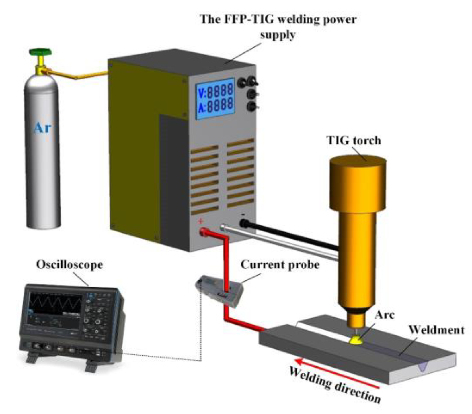
2. Equipment and Experimental Methods

An elementary diagram of the FFP-TIG system is shown in Figure 1. The FFP-TIG power supply (SCUT, Guangzhou, China) was designed to generate a FFP waveform in TIG welding. Through fast-frequency waveform modulation technology, the FFP-TIG power supply can output FFP waveforms. During the welding process, the current probe was clamped in the cable as shown in Figure 1, and the welding current was measured by oscilloscope. The current information was collected using HDO4104 high-definition oscilloscope (LeCory, New York, NY, USA) with a current probe of 500 A and 2 MHz CP500. As shown in Figure 2, the FFP-TIG power supply changes the steady direct current IM and the FFP current ID to modulate the waveform. The duty cycle is 50% and the frequency is 10–30 kHz. In this case, the welding current is a pulsed current with a peak value of ID + IM and a base value of IM. Since the duty cycle is 50%, the average current is IM + ID/2.
An IN-718 alloy plate of 4 mm thickness was used as the base metal. The chemical composition of IN-718 alloy is shown in Table 1. The surface of the IN-718 alloy plate was cleaned with an acetone solution before welding. The welding parameters are given in Table 2. Two cases were adopted to research the effect of arc behavior on the weld molten pool by FFP-TIG, as shown in Table 3. Case 1 studied the influence of FFP current on arc behavior on the weld molten pool. A pulsed frequency of 20 kHz was used. Case 2 studied the influence of FFP frequency on arc behavior on the weld molten pool. AN FFP current of 50 A was used.
In FFP-TIG, the arc shape changed under the action of FFP current. Figure 3 shows that the change in arc shape was reflected in the arc diameter and arc area. The arc diameter and arc area were calculated by using the pixel statistics program written by OpenCV in Python 3.0. A high-speed photography test platform was built to analyze the arc shape of the IN-718 alloy welding process. A CamRecord CL600 × 2 high-speed industrial camera (Optronis GmbH, Kehl, Germany) was used, with a resolution of 1280 × 1024, a frame rate of 500 frames/s, and a Nikon (Tokyo, Japan) AF MICRO-NIKKOR 60 mm F/2.8D lens. Chroma filters were used to mitigate the amount of light traveling to the high-speed industrial camera, as shown in Figure 3.
The small-hole-probe method was used to measure the arc pressure. The measuring device was composed of a DCB9419 pressure and liquid level measurement device (measurement accuracy: ±0.5% FS ± 1 word), a control instrument, and a water-cooled copper plate. We placed the copper plate directly under the TIG welding gun to make the welding gun arc on the copper plate, then moved the welding gun to make the arc pass through the measuring hole on the copper plate. The arc pressure at the hole was measured by the instrument. An infrared thermal camera (Chauvin, Dover, NH, USA Arnoux 1889-3, repeat accuracy: ±3 °C) was used to gather the infrared image of the FFP-TIG arc, as shown in Figure 4. The surface welding of beads was observed by an OM (Leica, DMI3000M, Wetzlar, Germany) after being etched with an etching solution of 6 mL HCL + 1 g CrO3+2 mL H2O. The width and area of the weld metal were measured to evaluate the effects of the welding processes on the surface welding.

3. Results and Discussion

3.1. Arc Behavior Analysis of the FFP-TIG Arc

In FFP-TIG, the fast-frequency arc shape does not have the characteristics of a low-frequency arc shape. The fast-frequency arc was replaced by a stable contractile arc. Research indicates that the addition of FFP current with a constant amplitude can create a contractile arc, which means that the stability of the arc is enhanced. In order to express the effect of FFP current with different amplitudes and frequencies on the arc shape, the arc shape parameters such as arc diameter and arc area were quantitatively calculated.
Figure 5 shows the welding waveforms and arc shape images for case 1. The stable output FFP waveforms obtained by self-developed welding power provided a guarantee for arc reshape in FFP-TIG. The arc shape was changed by adding FFP current with different amplitudes. The output FFP waveforms were stable and regular, and the FFP currents with different amplitudes are shown in Figure 5a. The arc images for case 1 are shown in Figure 5a. Comparing Figure 5a with Figure 5b, the arc diameter and arc area are significantly reduced under fast-frequency waveforms. The fast-frequency waveform contains the FFP current with a frequency of 20 kHz, and the generated electromagnetic field contracts the arc, forming a cylindrical contractile arc. At the same time, the increase in FFP current leads to the decrease in average current and the further decrease in arc diameter. Comparing Figure 5b, the larger the FFP current amplitude, the smaller the arc diameter and arc area. As shown in the arc diameter and arc area of the different welding waveforms, the arc diameter and arc area are measured to be 13.21 mm and 81.45 mm2, respectively, in conventional TIG. When the FFP current amplitude is increased to 50 A, the arc diameter and arc area are measured to be a minimum of 9.92 mm and 64.13 mm2, respectively. Compared with conventional TIG, the arc diameter and arc area in FFP-TIG with the FFP parameter of 50 A/20 kHz are reduced by 24.9% and 21.3%, respectively.
Figure 6 shows the welding waveforms and arc shape images for case 2. Arc shape was changed by adding FFP current with different frequencies. The output FFP waveforms were stable and regular, with the different FFP frequencies as shown in Figure 6a. The arc images for case 2 are shown in Figure 6a. Comparing Figure 6a, the larger the FFP current frequency, the smaller the arc diameter and arc area. As shown in Figure 7b, when the FFP frequency is increased to 30 kHz, the arc diameter and arc area are measured to be a minimum of 8.16 mm and 45.38 mm2, respectively. Compared with the FFP parameter of 50 A/10 kHz (10.5 mm and 61.41 mm2), the arc diameter and arc area in FFP-TIG with the FFP parameter of 50 A/30 kHz are reduced by 22.3% and 26.1%, respectively.
From the above, it can be inferred that the arc energy is more concentrated under the action of FFP-TIG than in conventional TIG. Meanwhile, the high-temperature area is affected by the outer arc area, and the external diffusion is well-controlled. With an increase in the FFP current amplitude or frequency, the arc diameter and arc area are reduced, while the arc energy is more concentrated.

3.2. Arc Pressure Analysis of the FFP-TIG Arc

The contact method was used to measure the arc pressure in the welding pool in real time, and the arc pressure values were collected by a pressure transducer under different welding waveforms. In Figure 8, the arc pressure values measured by the pressure transducer are the vertical axis, and the distance between the arc and the measuring hole are the horizontal axis. The arc pressure is normally distributed as a whole, and the arc pressure is symmetrically distributed with the change in FFP current amplitude or frequency.
Figure 8a shows the arc pressure for case 1. The arc pressure was changed by adding FFP current with different amplitudes. The arc pressure is measured to be 0.23 kPa in conventional TIG. When the FFP current amplitude is increased to 50 A, the arc pressure is measured to be a maximum of 0.39 kPa. For the same FFP frequency of 20 kHz, a higher FFP current amplitude results in a greater arc pressure. The arc pressure away from the arc center exhibits a downward trend: the arc pressure at the edge of the arc changes less, and the arc pressure near the arc center changes more. Results show that a higher current (60 A constant welding current) results in lower pressure than a lower average current of pulsed waveforms. That would indicate that the high-frequency pulsation exerts a stronger influence than the current value. Compared with conventional TIG, the arc pressure in FFP-TIG with the FFP parameter of 50 A/20 kHz is raised by 69.5%.
Figure 8b shows the arc pressure for case 2. The arc pressure was changed through adding FFP current with different frequencies. When the frequency is changed, the arc pressure changes and the arc pressure at the edge of the arc still fluctuates up and down with a small amplitude, but the arc pressure does not decline. The change amplitude of the arc pressure near the center of the arc is still large, and the arc pressure at the center of the arc is still the largest. When the FFP frequency is increased to 30 kHz, the arc pressure is measured to be a maximum of 0.47 kPa. For the same FFP current amplitude of 50 A, a higher FFP frequency results in a greater arc pressure.
With an increase in the FFP current amplitude or frequency, the arc pressure at the center of the arc increases greatly. This is because the plasma in the arc changes its motion trajectory and speed under the action of magnetic field force after the contract magnetic field is applied. The motion state of plasma in the arc is different under the action of FFP current, resulting in different variation amplitudes of arc pressure at different amplitudes and frequencies.

3.3. Infrared Image Analysis of FFP-TIG Arc Welding

In FFP-TIG, a change in fast-frequency arc shape will affect the arc energy concentration. Infrared images of FFP-TIG arc welding with different welding waveforms were taken with an infrared thermal camera, as shown in Figure 9 and Figure 10. The arc is a high-temperature ionized gas (also known as arc plasma) which is generated by the ionization of inert gas in the welding process. Therefore, under the same inert gas flow, the larger the proportion of high-temperature ionized gas in the inert gas as a whole, the more scattered the arc energy and the higher the arc energy divergence. In addition to the high-temperature ionized gas, the remaining gas in the inert shielding gas acts as the welding inert gas. In order to express the effect of FFP current with different amplitudes and frequencies on the arc energy divergence, the pixels number of high-temperature ionized gas (arc plasma) area and the pixels number of inert gas area were quantitatively calculated. The statistical data were calculated by the pixel statistics program written by OpenCV in Python. Considering that there is a large temperature gradient between the high-temperature ionized gas area and the inert gas area, which corresponds to the narrow yellow temperature zone (800~1000 °C) in Figure 9 and Figure 10, the red temperate zone was defined as the high-temperature ionized gas area and the green temperature zone as the inert gas area.
Figure 9 shows the infrared images of FFP-TIG arc welding for case 1. Arc temperature and arc energy divergence were changed by adding FFP current with different amplitudes. The arc temperature and arc energy divergence are measured to be 1662 °C and 67.1% in conventional TIG. As shown in Figure 9f, when the FFP current amplitude is increased to 50 A, the arc temperature and arc energy divergence are measured to be 1175 °C and 48%, respectively. For the same FFP frequency of 20 kHz, a higher FFP current amplitude results in a lower arc temperature and arc energy divergence. When welding current values are maintained at 60 A, a decrease in steady direct current value and an increase in FFP current value will reduce the average equivalent current to reduce the arc temperature and heat input. Meanwhile, with an increase in the FFP current amplitude, the arc divergence decreases greatly due to the increase of the contraction magnetic field intensity acting on the arc plasma. The arc energy divergence and arc temperature in FFP-TIG with the FFP parameter of 50 A/20 kHz are reduced by 19.1 and 29.3%, respectively.
Figure 10 shows the infrared images of FFP-TIG arc welding for case 2. The arc energy divergence was reduced by adding FFP current with higher frequencies. Since the welding current value and average equivalent current were constant, the arc temperature of several groups in experiments was similar. When the FFP frequency is increased to 30 kHz, the arc energy divergence is measured to be 43.3%. For the same FFP current amplitude of 50 A, a higher FFP frequency results in a lower arc energy divergence.
According to the above study, the contraction magnetic field has strictly restricted the plasma movement in the arc. Compared with a conventional TIG arc with plasma in a free state, the FFP-TIG arc contracts obviously. This is bound to have an impact on the arc energy divergence. With an increase in the FFP current amplitude or frequency, the arc energy divergence reduces greatly. The high-temperature area of the FFP-TIG arc is concentrated in the center of the weld melting surface, which can prevent the excessive diffusion of heat input to the base metal. Therefore, the FFP-TIG arc had a good arc energy concentration, which would result in the good melting effect on a base metal, and reduce the impact on the heat-affected zone.

3.4. Surface Welding Analysis of FFP-TIG

The change in arc shape and arc pressure will inevitably affect the surface welding. To uncover the effect of the fast-frequency waveform on the surface welding of IN-718 beads, we obtained the surface welding under the action of FFP current amplitude or frequency.
Figure 11 shows the surface welding for case 1. The surface welding of IN-718 beads obtained by conventional TIG welding is shown in Figure 11a. The surface welding of IN-718 beads obtained by FFP-TIG is shown in Figure 11b–f. As shown in Figure 11, when welding current values are maintained at 60 A, the increase in FFP current value reduces the average equivalent current to reduce the heat input in the bead. Therefore, the heat input of conventional TIG is higher than that of FFP-TIG. The weld width and weld penetration measurements of conventional TIG without the FFP are 4.88 mm and 1.53 mm, respectively. When the FFP frequency remains constant at 20 kHz and the FFP current amplitude is increased to 50 A in FFP-TIG, the weld width and weld penetration are measured to be 3.71 and 1.26 mm. The larger the FFP current amplitude, the lower the weld width, and the greater the weld penetration. Compared with that of conventional TIG, the weld width of the FFP-TIG with the FFP parameter of 50 A/20 kHz is approximately 23.98% smaller.
Figure 12 shows the surface welding for case 2. The surface welding of IN-718 beads obtained by FFP-TIG is shown in Figure 12. When the FFP current amplitude remains constant at 50 A and the FFP frequency is increased to 30 kHz in FFP-TIG, the weld width and weld penetration are measured to be 3.46 and 1.37 mm, respectively. As shown in Figure 13, the higher the FFP frequency, the lower the weld width, and the greater the weld penetration.
According to the results of arc behavior, arc pressure, and welding pool infrared image analysis, a change in arc and molten pool behavior leads to a change in surface welding by adding FFP current. The arc core is the maximum-temperature region of the welding arc; its temperature and pressure determine the contours of the molten pool. With an increase in the FFP current amplitude and FFP frequency, the arc pressure and arc core temperature increased. This resulted in the weld width decreasing, and the weld penetration increasing, in IN-718 beads. The higher the FFP current amplitude or frequency, the stronger the arc contraction effect, the smaller the weld width, and the greater the weld penetration. The modification of the fast-frequency waveform arc energy is the root of the evolution of surface welding.
As shown in Figure 14, the grain size of an Inconel 718 nickel-based superalloy FFP-TIG weld joint decreases with increasing frequency. Increasing the fast-frequency pulsed current amplitude or fast-frequency pulsed frequency enhances the stirring effect of the molten pool. Increasing the fast-frequency pulsed current amplitude increases the amplitude of the stirring of the molten pool and the volume of liquid metal participating in the stirring of the molten pool, while increasing the fast-frequency pulsed frequency increases the frequency of the stirring of the molten pool, resulting in the rapid crushing of grains in the growth process. In FFP-TIG, the stirring effect is conducive to accelerating the thermal convection flow cycle, making the FFP-TIG molten pool temperature drop rapidly and heat dissipate uniformly, which makes contributions to refining equiaxial grains.

3.5. Mechanism of FFP-TIG Arc Contraction

The electromagnetic field generated by fast-frequency current contracts the FFP-TIG arc, which is called the self-magnetic contraction effect. The self-magnetic contraction effect of the FFP-TIG arc needs to be analyzed according to electromagnetic theory.
By placing two current-carrying wires together in parallel, each current-carrying wire will generate a magnetic field around itself, and the magnetic fields generated by the two current-carrying wires will interact with each other. If the current direction of the two current-carrying wires is the same, it will produce an attractive electromagnetic force. Based on this principle, the discrete analysis of the arc is carried out, as shown in Figure 15. The arc can be regarded as a conductor composed of numerous parallel current lines, which have the same electric direction and generate attraction between each other, thus causing a trend of contraction in the radial direction of the arc. However, the contraction trend is affected by the gas pressure gradient inside the arc, as shown in Equation (1):
d P d r + j z · B φ = 0
where P is the gas pressure inside the arc, j z is the axial current density, and B φ is the arc self-magnetic field intensity.
Considering the arc as an ideal cylinder, according to the above formula, the pressure in the center of the arc is the largest. The relationship between the intensity of the self-magnetic field and the current can be obtained from the ampere circuital theorem, as shown in Equation (2):
l   B · d I = μ 0 I
where μ is the vacuum permeability and I is the algebraic sum of current contained in loop l.
Since the magnetic field strength B is always in the tangent direction of the arc cylinder cross-section, B is in the same direction as a point dl in the arc interface, and B = B φ , so Equation (2) can be expressed as Equation (3):
B φ = μ 0 r 0 r j z r d r
Substitute Equation (3) into Equation (1) to obtain Equation (4):
d P d r + μ 0 j z r 0 r j z r d r = 0
Suppose the pressure at the arc boundary is P 0 , and use Equation (4) to integrate radially to the center along the arc column to obtain Equation (5):
P r P 0 = μ 0 r * r j z r 0 r j z r d r d r
Transformed:
Δ P r = P r P 0 = μ 0 r r * j z r 0 r j z r d r d r
where Δ P r is the pressure change due to self-magnetic contraction at the radius r of the arc.
The value of Δ P m a x is discussed in two cases:
The current density distribution of the arc is constant, as shown in Equation (7):
j z = I 2 π r 2 = const  
substitute Equation (7) into Equation (6) to obtain Equation (8):
Δ P r = μ 0 4 π · I 2 π r * 2 · 1 r 2 r * 2
Therefore, the maximum self-magnetic contraction produced at the central axis of the arc is as shown in Equation (9):
Δ P m a x = Δ P 0 = μ 0 4 π · I 2 π r * 2
The current density distribution of the arc is parabolic, as shown in Equation (10):
j z = j m · 1 r 2 r * 2
where j m is the current density on arc axis, substitute Equation (10) into Equation (6) and perform a Fourier transform to obtain Equation (11):
P r = 5 3 · μ 0 4 π · I 2 π r * 2 · 1 12 5 · r 2 r * 2 + 9 5 · r 4 r * 4 2 5 · r 6 r * 6
Therefore, the maximum self-magnetic contraction produced at the central axis of the arc is as shown in Equation (12):
Δ P m a x = Δ P 0 = 5 3 · μ 0 4 π · I 2 π r * 2
From the above derivation results, the arc radial pressure caused by the self-magnetic contraction effect is directly proportional to the square of the arc current, and inversely proportional to the arc radius. The arc radial pressure is related to the current density distribution of the arc. When the current density distribution of the arc axis is steeper, the arc radial pressure is larger. The highest current density of the arc is concentrated in the center of the arc, so the value of the self-magnetic contraction effect changes from high to low around the middle axis.
When the FFP current changes periodically, the FFP-TIG arc increases the maximum current in the cycle by increasing the time distribution state of energy (i.e., increasing the FFP current amplitude) to improve the self-magnetic contraction effect in the cycle. With an increase in FFP frequency, the frequency of self-magnetic contractions increases, and the FFP-TIG arc contraction becomes more obvious. At the same time, the average arc voltage decreases because the electrode temperature change does not follow the ultra-fast change of current [27].
Due to the self-magnetic contraction effect, the electromagnetic dynamic pressure force pushes the high-temperature ionized gas at the small cross section arc cylinder towards the workpiece. Meanwhile, new inert gas is continuously added around the tungsten electrode. The gas is heated and ionized when entering the arc area, forming a continuous high-temperature ionized gas flow, and impacting the surface of the molten pool.
Figure 15 shows the schematic diagram of the electromagnetic dynamic pressure force model in the arc. The main influencing factors of electromagnetic dynamic pressure force F r 1 include gas flow velocity, welding current value, arc shape, arc length, etc. The expression of electromagnetic dynamic pressure force is shown as Equation (13):
F r 1 = P m a x · exp a r 1
where P m a x is the current pressure on arc axis, a is the concentration factor of the distribution curve, and r 1 is the distance between a point in the arc and the central axis of the arc.
Suppose the angle between the electromagnetic dynamic pressure force and the molten pool is θ , and the electromagnetic dynamic pressure force F r 1 is divided into an axial force F r 1 z and a radial force F r 1 r , as shown in Equation (14):
  F r 1 z = F r 1 sin θ   F r 1 r = F r 1 cos θ
As shown in Figure 16, from the above derivation results, the axial force F r 1 z would make the surface of the molten pool concave, which is conducive to the heat source flowing down and increasing the weld penetration. The radial force F r 1 r would make the surface of the molten pool subject to radial tensile force and increase the weld width. In FFP-TIG, with an increase in the FFP current amplitude or frequency, the self-magnetic contraction effect enhances, and the angle θ increases. According to Equation (14), the axial force F r 1 z increases while the radial force F r 1 r decreases. When the electromagnetic dynamic pressure force F r 1 is acting on the molten pool, it is beneficial to increase the weld penetration and decrease the weld width. Finally, the surface welding in Section 3.4 confirms the influence of electromagnetic dynamic pressure force in FFP-TIG on the molten pool. The higher the FFP current amplitude or frequency, the stronger the arc contraction effect, the smaller the weld width, and the greater the weld penetration.

4. Conclusions

  • With an increase in the FFP current amplitude or frequency, the arc diameter and arc area were reduced. Compared with conventional TIG, the arc diameter and arc area of FFP-TIG were reduced by approximately 38.2% and 29.2%, respectively.
  • There was a significant increase in arc pressure by FFP-TIG. The arc pressure is normally distributed as a whole, and the arc pressure is symmetrically distributed with a change in FFP current amplitude or frequency. With an increase in the FFP current amplitude or frequency, the arc pressure at the center of the arc increased greatly.
  • In FFP-TIG, the change in fast-frequency arc shape affects the arc energy concentration. The arc energy divergence and arc temperature in FFP-TIG with the FFP parameter of 50 A/20 kHz are reduced by approximately 19.1 and 29.3%, respectively. With an increase in the FFP current amplitude or frequency, the arc energy divergence reduced greatly.
  • With the effects of FFP-TIG, a change in arc and molten pool behavior leads to a change in surface welding by adding FFP current. The higher the FFP current amplitude or frequency, the stronger the arc contraction effect, the smaller the weld width, and the greater the weld penetration.

Author Contributions

J.W.: Investigation, Validation, Visualization, Formal analysis, Writing—original draft, Writing—review & editing; Z.W.: Conceptualization, Investigation, Methodology, Validation, Formal analysis, Funding acquisition, Project administration; Z.Z.: Methodology, Validation, Funding acquisition, Project administration; W.F.: Conceptualization, Investigation, Methodology, Validation, Visualization, Formal analysis, Writing—original draft; S.L.: Writing—original draft, Writing—review & editing, Funding acquisition, Project administration; X.C.: Investigation, Methodology, Validation, Visualization, Formal analysis; J.T.: Investigation, Methodology, Validation, Visualization, Formal analysis; C.G.: Writing—review & editing, Funding acquisition, Project administration. All authors have read and agreed to the published version of the manuscript.

Funding

This research was funded by State Key Lab of Advanced Welding and Joining, Harbin Institute of Technology, grant number (AWJ-23M03). National Natural Science Foundation of China, grant number (U2141216). Guangzhou Science and Technology Plan Project grant number (2023A04J1584). Shenzhen Science & Technology Program, grant number (JSGG20201201100400001). Natural Science Foundation of Guangdong Province, grant number (2021B1515420006, 2021B1515120026). Program of Marine Economy Development Special Fund (Six Marine Industries) under the Department of Natural Resources of Guangdong Province, grant number (GDNRC 202146) and Zhuhai Science and Technology Project, grant number (ZH22017001210029PWC).

Data Availability Statement

No new data were created or analysed in this study.

Conflicts of Interest

The authors declare no conflict of interest.

References

  1. Qi, B.; Xu, H.; Zhang, W. Microstructure and property analysis of 0Cr18Ni9Ti joints welded by ultra-sonic pulse tungsten-inert-gas welding technology. J. Beijing Univ. Aeronaut. Astronaut. 2009, 35, 132–136. [Google Scholar]
  2. Dai, W.L. Effects of high-intensity ultrasonic-wave emission on the weldability of aluminum alloy 7075-T6. Mater. Lett. 2003, 57, 2447–2454. [Google Scholar] [CrossRef]
  3. Short, A.B. Gas tungsten arc welding of alpha plus beta titanium alloys: A review. Mater. Sci. Technol. 2009, 25, 309–324. [Google Scholar] [CrossRef]
  4. Li, L.; Yang, M.; Qi, B.; Liu, H. Study of high frequency pulsed arc on molten pool thermal properties of Ti-6Al-4V. J. Manuf. Process. 2019, 38, 308–312. [Google Scholar] [CrossRef]
  5. Wang, Z.; Jiang, D.; Wu, J.; Xu, M. A review on high-frequency pulsed arc welding. J. Manuf. Process. 2020, 60, 503–519. [Google Scholar] [CrossRef]
  6. Yang, M.; Zheng, H.; Qi, B.; Yang, Z. Effect of arc behavior on Ti-6A1-4V welds during high frequency pulsed arc welding. J. Mater. Process. Technol. 2017, 243, 9–15. [Google Scholar] [CrossRef]
  7. Wu, J.; Wang, Z.; Lin, S.; Xie, Z.; Xu, M.; Tian, J.; Guo, C. Effect of fast-frequency pulsed waveforms on the microstructure and mechanical properties of Ti-6Al-4V alloy welded by FFP-TIG. J. Mater. Res. Technol. 2022, 20, 516–531. [Google Scholar] [CrossRef]
  8. Wu, J.; Xu, M.; Lin, S.; Zhang, Q.; Wu, X.; Tian, J.; Wang, Z. Refining microstructures and enhancing mechanical properties of Inconel 718 weldment via fast-frequency double pulsed waveforms adopting in FFP-TIG. J. Mater. Process. Technol. 2023, 314, 117882. [Google Scholar] [CrossRef]
  9. Farzadi, A.; Serajzadeh, S.; Kokabi, A.H. Modeling of heat transfer and fluid flow during gas tungsten arc welding of commercial pure aluminum. Int. J. Adv. Manuf. Technol. 2008, 38, 258–267. [Google Scholar] [CrossRef]
  10. Balasubramanian, M.; Jayabalan, V.; Balasubramanian, V. Effect of pulsed gas tungsten arc welding on corrosion behavior of Ti-6Al-4V titanium alloy. Mater. Des. 2008, 29, 1359–1363. [Google Scholar] [CrossRef]
  11. Babu, N.K.; Raman, S.G.S. Influence of current pulsing on microstructure and mechanical properties of Ti–6Al–4V TIG beads. Sci. Technol. Weld. Join. 2006, 11, 442–447. [Google Scholar] [CrossRef]
  12. Giridharan, P.K.; Murugan, N. Optimization of pulsed GTA welding process parameters for the welding of AISI 304L stainless steel sheets. Int. J. Adv. Manuf. Technol. 2009, 40, 478–489. [Google Scholar] [CrossRef]
  13. Chen, S.J.; Zhang, B.L.; Yin, S.Y.; Wu, H.R. Effect on aluminum-alloy TIG welding quality of double pulse modulated variable polarity waveform. Electr. Weld. Mach. 2006, 36, 7–14. [Google Scholar]
  14. Balasubramanian, M.; Jayabalan, V.; Balasubramanian, V. A mathematical model to predict impact toughness of pulsed-current gas tungsten arc-welded titanium alloy. Int. J. Adv. Manuf. Technol. 2008, 35, 852–858. [Google Scholar] [CrossRef]
  15. Qi, B.J.; Yang, M.X.; Cong, B.Q.; Li, W. Study on Fast-Convert Ultrasonic Frequency Pulse TIG Welding Arc Characteristic. Mater. Sci. Forum 2011, 37, 704–705. [Google Scholar] [CrossRef]
  16. Cook, G.E.; Eassa, H.E.E.H. The Effect of High-Frequency Pulsing of a Welding Arc. IEEE Trans. Ind. Appl. 1985, 21, 1294–1299. [Google Scholar] [CrossRef]
  17. Sivaprasad, K.; Raman, S. Influence of magnetic arc oscillation and current pulsing on fatigue behavior of alloy 718 TIG weldments. Mater. Sci. Eng. A 2007, 448, 120–127. [Google Scholar] [CrossRef]
  18. Palani, P.K.; Murugan, N. Selection of parameters of pulsed current gas metal arc welding. J. Mater. Process. Technol. 2006, 172, 1–10. [Google Scholar] [CrossRef]
  19. Zacharia, T.; David, S.A.; Vitek, J.M.; Debroy, T. Weld pool development during GTA and laser beam welding of Type 304 stainless steel; Part I—Theoretical analysis. Weld. J. 1989, 68, 510s–519s. [Google Scholar]
  20. Sun, Q.J.; Lin, S.B.; Yang, C.L.; Zhao, G.Q. Penetration increase of AISI 304 using ultrasonic assisted tungsten inert gas welding. Sci. Technol. Weld. Join. 2009, 14, 765–767. [Google Scholar] [CrossRef]
  21. Reis, R.P.; Scotti, A.; Norrish, J.; Cuiuri, D. Investigation on Welding Arc Interruptions in the Presence of Magnetic Fields: Arc Length, Torch Angle and Current Pulsing Frequency Influence. IEEE Trans. Plasma Sci. 2013, 41, 133–139. [Google Scholar] [CrossRef]
  22. Huang, Y.; Liu, R.L.; Hao, Y.Z. Gas Pool Coupled Activating TIG Welding Method with Coupling Arc Electrode. Chin. J. Mech. Eng. 2018, 6, 8. [Google Scholar] [CrossRef]
  23. Ghosh, P.K.; Dorn, L.; Hübner, M.; Goyal, V.K. Arc characteristics and behaviour of metal transfer in pulsed current GMA welding of aluminium alloy. J. Mater. Process. Technol. 2007, 194, 163–175. [Google Scholar] [CrossRef]
  24. Onuki, J.; Anazawa, Y.; Nihei, M.; Katou, M.; Onuma, A.; Funamoto, T. Development of A New High-Frequency, High-Peak Current Power Source for High Constricted Arc Formation. Jpn. J. Appl. Phys. 2002, 41, 5821–5826. [Google Scholar] [CrossRef]
  25. Kumar, A.; DebRoy, T. Calculation of three-dimensional electromagnetic force field during arc welding. J. Appl. Phys. 2003, 94, 1267–1277. [Google Scholar] [CrossRef]
  26. Yang, M.X.; Qi, B.J.; Cong, B.Q.; Li, W. Influence of pulse current parameters on arc behavior by austenite stainless steel. Hanjie Xuebao/Trans. China Weld. Inst. 2012, 33, 67–70. [Google Scholar]
  27. da Cunha, T.V.; Bohórquez, C.E.N. Effects of current pulsation at ultra-high frequency on physical aspects of the arc and its implications in the weld bead morphology in the GTAW process. Weld World 2021, 65, 251–261. [Google Scholar] [CrossRef]
Figure 1. Schematic diagram of the FFP-TIG experimental system.
Metals 13 00848 g001
Figure 2. Schematic diagram of waveform formation.
Metals 13 00848 g002
Figure 3. High-speed photography system.
Metals 13 00848 g003
Figure 4. Schematic diagram of FFP-TIG arc infrared image shooting.
Metals 13 00848 g004
Figure 5. Welding waveforms and arc shapes: (a) 0 A/0 kHz; (b) 10 A/20 kHz; (c) 20 A/20 kHz; (d) 30 A/20 kHz; (e) 40 A/20 kHz; (f) 50 A/20 kHz.
Metals 13 00848 g005
Figure 6. Welding waveforms and arc shapes: (a) 50 A/10 kHz; (b) 50 A/15 kHz; (c) 50 A/20 kHz; (d) 50 A/25 kHz; (e) 50 A/30 kHz.
Metals 13 00848 g006
Figure 7. The arc diameter and arc area of the different welding waveforms: (a) case1; (b) case2.
Metals 13 00848 g007
Figure 8. The arc pressure of the different welding waveforms: (a) case1; (b) case2.
Metals 13 00848 g008
Figure 9. Infrared images of FFP-TIG arc welding in different welding waveforms: (a) 0 A/0 kHz; (b) 10 A/20 kHz; (c) 20 A/20 kHz; (d) 30 A/20 kHz; (e) 40 A/20 kHz; (f) 50 A/20 kHz.
Metals 13 00848 g009
Figure 10. Infrared images of FFP-TIG arc welding in different welding waveforms: (a) 50 A/10 kHz; (b) 50 A/15 kHz; (c) 50 A/20 kHz; (d) 50 A/25 kHz; (e) 50 A/30 kHz.
Metals 13 00848 g010
Figure 11. The surface welding of the different welding waveforms: (a) 0 A/0 kHz; (b) 10 A/20 kHz; (c) 20 A/20 kHz; (d) 30 A/20 kHz; (e) 40 A/20 kHz; (f) 50 A/20 kHz.
Metals 13 00848 g011
Figure 12. The surface welding of the different welding waveforms: (a) 50 A/10 kHz; (b) 50 A/15 kHz; (c) 50 A/20 kHz; (d) 50 A/25 kHz; (e) 50 A/30 kHz.
Metals 13 00848 g012
Figure 13. The average weld width and penetration of IN-718 beads by different welding waveforms.
Metals 13 00848 g013aMetals 13 00848 g013b
Figure 14. The average grain size of IN-718 beads by different welding waveforms.
Metals 13 00848 g014
Figure 15. The diagram of the self-magnetic contraction effect.
Metals 13 00848 g015
Figure 16. Schematic diagram of the electromagnetic dynamic pressure force model in the arc.
Metals 13 00848 g016
Table 1. Chemical composition of IN-718 alloys (mass fraction wt %).
NiCrFeCMnSiMoCuCoAlTi
Min5017Bal.------2.8----0.20.65
Max5521 0.080.350.353.30.31.00.81.15
Table 2. Welding parameters.
Welding CurrentWelding VoltageWelding SpeedShield Gas Flow (Ar)Electrode Diameter
10~60 A10 V2 mm/s15 L/min2 mm
Table 3. Waveform parameters.
Case 1
Welding Current (A)FFP Current/ID (A)Steady Direct Current/IM (A)Frequency (kHz)Average Current (A)
60/60060/60
60/50105020D55
60/4020402050
60/3030302045
60/2040202040
60/1050102035
Case 2
Welding Current (A)FFP Current/ID (A)Steady Direct Current/IM (A)Frequency (kHz)Average Current (A)
60/1050101035
60/1050101535
60/1050102035
60/1050102535
60/1050103035
Disclaimer/Publisher’s Note: The statements, opinions and data contained in all publications are solely those of the individual author(s) and contributor(s) and not of MDPI and/or the editor(s). MDPI and/or the editor(s) disclaim responsibility for any injury to people or property resulting from any ideas, methods, instructions or products referred to in the content.

