Article

Influence of Oxy-Fuel Lance Parameters on the Scrap Pre-Heating Temperature in the Hot Metal Ladle

1
School of Metallurgy, Northeastern University, Shenyang 110819, China
2
School of Metallurgical Engineering, Xi’an University of Architecture and Technology, Xi’an 710055, China
*
Author to whom correspondence should be addressed.
Metals 2023, 13(5), 847; https://doi.org/10.3390/met13050847
Submission received: 29 March 2023 / Revised: 21 April 2023 / Accepted: 24 April 2023 / Published: 25 April 2023

Abstract

:
As one of the vital ways to improve the converter heat balance and increase the scrap ratio, scrap pre-heating technology has attracted much attention from researchers. The aim of this paper is to reveal the effect of the oxy-fuel lance parameters on the temperature field, flow field, and scrap pre-heating temperature in the ladle by means of numerical simulations. For this, a three-dimensional mathematical model containing the turbulence model, the porous medium heat balance model, and other models has been developed. The research results show that the rational and correct choice of gas flow rate, lance position, and nozzle angle has an important influence on the temperature field and the average scrap temperature. When the gas flow rate increases, the internal annular combustion zone of the scrap gradually expands, the cold zone at the bottom of the scrap continues to decrease, and the average scrap temperature keeps increasing. When the gas flow rate is 5000 m3/h, and the average scrap temperature reaches 1197 K, the pre-heating time is 9.98 min. Lowering the oxy-fuel lance position helps to reduce the cold zone at the bottom of the scrap and increases the average temperature in the cold zone. Reasonable selection of the nozzle angle is conducive to improving the uniformity of the flow field. When the angle of the nozzle is 15°, the gas circulation zone is the largest, and the time to reach an average scrap temperature of 1197 K is the shortest.

1. Introduction

As an important renewable resource, scrap is of great significance to the steel industry in reducing energy consumption, reducing environmental pollution, and achieving green development [1]. Steelmaking with scrap instead of iron ore [2,3,4], producing 1 t of crude steel on average, can reduce iron ore consumption by 4.3 t, smelting energy consumption by 60%, water consumption by 40%, waste gas emissions by 86%, sewage discharge by 76%, etc. Academician Lu emphasized [5]. the importance of using more scrap and less iron ore in the steel industry and conceived a life cycle iron flow diagram with the concept of time for steel products. Additionally, he proposed the scrap index (S), an indicator to measure the adequacy of scrap resources in the steel industry, and estimated the S values [6]. for China, Japan, and the U.S. from 1988 to 1997, and discussed the process structure of the steel industry in the three countries on this foundation. Junichiro et al. [7] argue that primary steelmaking will remain the dominant process for steelmaking until at least 2050.
Improving the scrap ratio of the converter steelmaking process has been a hot topic of research for scholars at home and abroad. In the 1960s, foreign steel companies added heat-increasing agents to make up for the heat in the converter smelting process; common heat-increasing agents such as calcium carbide [8], silicon carbide, etc. Several researchers have found that enhancing the exothermic process of carbon and oxygen reactions in the converter can also increase the scrap ratio [9]. For example, Japan’s Sumitomo Metals [10] industrial trial study found that the heat absorption rate of secondary combustion in the 15 t converter was close to 100% and the scrap ratio could be increased by 9%; the heat absorption rate in the 160 t converter reached up to 70% and the scrap ratio increased by only 6%.
Burner scrap pre-heating technology can effectively increase the amount of scrap used in the converter and recover gas from the converter [11]. The fuels used in the pre-heating process include natural gas [12,13], fuel oil [14], etc. Under laboratory conditions, Entremont et al. [15] achieved an all-scrap converter smelting by scrap pre-heating outside the furnace and supplementing the converter with heat-increasing agents. The heat transfer behaviors of the scrap pre-heating process directly affect important process indicators such as pre-heating temperature and gas consumption. Yu et al. [16] presented for the first time a novel two-cell and stacking approach to simulate the pre-heating and melting of porous scrap and its dynamic collapse process. Carlsson et al. [17] studied the effect of different scrap categories on the electrical energy consumption of the electric arc furnace process. Nugumanov et al. [18] used numerical simulations to study the heat transfer behaviors between the coal and the scrap in the converter and derived the relationship between the scrap heating time, the scrap temperature, and hot metal quality. Mandal et al. [19] first developed a numerical model for heat transfer between the burner gas and the scrap, and the results showed that the burner heat transfer efficiency increased significantly when the scrap porosity was reduced. In addition, the researchers found that adjusting the scrap pre-heating process parameters also helped to improve the scrap pre-heating effect. As Norio et al. [20] tested the basic performance of the new scrap preheater Multistage Super Preheater (MSP), the results show that the average temperature of the scrap after 30 min pre-heating is 500~600 °C and the pre-heating efficiency is 35~45%. Yuan et al. [21] have simulated numerically the flame combustion characteristics of ladle nozzles with different internal structures; the results show that the best temperature uniformity inside the ladle is achieved when the jet angle is 20°, and the nozzle is equipped with four air holes inside.
Compared to fuels such as fuel oil and coal, the coke oven gas, blast furnace gas, and converter gas used in oxy-fuel lance scrap pre-heating technology offer an effective path to carbon reduction [22], which not only improves energy efficiency [23] but also offers huge energy-saving potential [24,25,26]. Wu et al. [27] found that adjusting the gas flow rate or the negative pressure at the outlet achieved the best results for scrap baking in the hot metal ladle. Zhan et al. [28] studied the effect of oxy-fuel lances using different spray patterns and methods on the scrap pre-heating. The results show that for single-hole oxy-fuel lance using A-B-A type O2-CO-O2 type, the flow field and temperature field are uniform.
Current research on the pre-heating process of scrap is mostly focused on preheater efficiency, porosity, and airflow characteristics. In this regard, this paper analyses the gas flow and heat transfer behaviors of the scrap pre-heating process by constructing a numerical model and systematically discusses the effects of different gas flow rates, oxy-fuel lance positions, and oxy-fuel lance nozzle angles on the temperature and flow fields in the hot metal ladle, and investigates the scrap heating curve and scrap temperature distribution law at different locations during the pre-heating process.

2. Mathematical Model

2.1. Flow Field for Hot Metal Ladle

The standard k-ε turbulence model describes these turbulence behaviors well and is used to good effect with high computational accuracy. The governing equations [29] are shown in Equations (1) and (2).
t ( ρ k ) + ( ρ k v ) = [ ( μ + μ t σ k ) k ] + G k ρ ε
t ( ρ ε ) + ( ρ ε v ) = [ ( μ + μ t σ ε ) ε ] + C 1 e ε k G k C 2 ε ρ ε 2 k
where ρ represents the fluid density (kg/m3), k represents the turbulent kinetic energy (m2/s2), ν represents the velocity vector of the fluid (m/s), t represents the flow time (s), μ represents the dynamic viscosity of the gas (m2/s), Gk represents the turbulent kinetic energy generated by the mean velocity gradient of the gas, ε represents the turbulent dissipation rate (m2/s3), C1ε and C2ε are constants (C1ε = 1.44, C2ε = 1.9), and σk and σε represent the Prandtl number of k and ε, respectively (σk = 1.0, σε = 1.2).

2.2. Combustion Model

The combustion reaction during the scrap pre-heating is a large flow rate non-premixed gas combustion [30]. Then, the Eddy Dissipation (E.D.) model is used to describe the overall chemical reaction rate. The reaction rate Ri for substance i in reaction r, r is given by the smaller of the expressions in Equations (3) and (4).
R i , r = v i , r M ω , i A ρ ε k min R ( Y R v R , r M ω , R )
R i , r = v i , r M ω , i A B ρ ε k P Y P j N v j , r M ω , j
where ν i , r and ν i , r " are the stoichiometric coefficients of reactant i and product j in reaction r, respectively, Mω,i and Mω,j are the molecular weights of the i and j substances, respectively, YR represents the mass fraction of a specific reactant, YP represents the mass fraction of any of the products, ν R , r represents the stoichiometric coefficient of a specific reactant in reaction r, Mω,r represents the molecular weight of a specific reactant, and A = 4.0 and B = 5.0 are empirical constants.

2.3. Porous Media Model

Porosity is a vital factor affecting heat transfer [31,32,33]. The single-phase flow, momentum, and energy equations [34] for a porous medium are shown in Equations (5) and (6).
t ( γ ρ v ) + ( γ ρ v v ) + γ p [ γ μ ( v + v T ) 2 3 γ v ] ( μ β + C 2 ρ 2 | v | v ) = 0
t ( γ ρ f E f + ( 1 γ ) ρ s E s ) + [ v ( ρ f E f + P ) ] = ( k e f f T i h i J i )
where γ represents the porosity, β represents the viscous resistance coefficient, C2 represents the inertia resistance coefficient, Ef represents the total fluid energy, ES represents the total solid medium energy, and ρf and ρS represent the densities of the fluid and solid, respectively.

2.4. Radiation Model

In this paper, the P-1 model is used to describe the radiative heat transfer behaviors during pre-heating, which assumes that all surfaces are diffusely reflected, and the radiation intensity is expressed using the spherical harmonic function [35], which has a high calculation accuracy, and the radiative heat flux qr is calculated using Equation (7).
q r = 1 3 ( a + σ s ) C σ s G
The bottom scrap radiation heat exchange process includes the behaviors of absorption, scattering, and release, and its heat exchange transport equation is shown in Equation (8).
q r = 4 π ( a n 2 σ T 4 π + E p ) + ( a + a p ) G
where a represents the ash absorption coefficient, calculated by the ash mass weighting model, σs represents the scattering coefficient, G represents the incident coefficient, C represents the linear anisotropy coefficient, σ represents the Stefan–Boltzmann constant (σ = 5.67 × 10⁸).

3. Calculation Methods and Conditions

3.1. Introduction of the Scrap Pre-Heating Process for the Hot Metal Ladle

Scrap pre-heating refers to the way in which scrap is added to the heating furnace or pre-heating equipment by using different thermal sources for pre-heating. The waste steel pre-heating process in the hot metal ladle is as follows. The hot metal ladle (capacity 90 t) is filled with 8–15 t of scrap using the scrap crane after the converter has been blended, the hot metal ladle is transported to the pre-heating station for 8 to 15 min, the scrap temperature reaches a certain temperature (around 1197 K) and then goes to the blast furnace to wait for picking up the hot metal.

3.2. Physical Modeling and Meshing

This paper examines the process of pre-heating scrap steel with an oxy-fuel oxy-furl lance in a hot metal ladle, modeling with SolidWorks software. Figure 1 shows the schematic diagram of the hot metal ladle. Figure 1a shows the longitudinal cross-section of the hot water ladle along the negative pressure vent, which was extended for subsequent analysis of the results. The height of the hot metal ladle is H1 of 3678 mm, the diameter Φ1 is 2474 mm, the diameter Φ2 of the negative pressure vent is 800 mm, the height H2 of the scrap is 1000 mm, the width H3 of the atmospheric pressure vent is 200 mm, H4 H4 is the oxy-fuel lance position, and θ is the lance nozzle angle.
The geometric model was meshed using ICEM CFD software (ICEM CFD 14.5). Figure 2 shows the gridding of the hot metal ladle. The calculation domain in the grid division includes the fluid zone (hot metal ladle) and the porous media zone (scrap zone). Figure 2b shows the gas inlet of the oxy-fuel lance head; the surrounding holes are the gas inlet, and the middle hole is the oxygen inlet. The distribution of the location of the gas inlet and atmospheric vent affects the flow and temperature fields of the hot metal ladle; therefore, the grid at the oxygen inlet, gas inlet, and atmospheric vent is refined to facilitate the observation and study of the local gas flow. Based on the grid independence analysis, the total number of grids was determined to be 532,369. Finally, numerical calculations were carried out using Fluent software (Fluent 14.5) software and post-processing of the data using CFD-Post software (CFD-Post 14.5 software) and Tecplot software (Tecplot 2021 software). The scheme for the numerical calculation is shown in Table 1.

3.3. Boundary Conditions and Solution Process

The boundary conditions are set according to the site pre-heating process parameters. The composition of the converter gas is shown in Table 2. As can be seen from this table, the H2 component of converter gas is relatively small, and the main combustible component is C.O., which has an ignition point of 938 K. To ensure full combustion of the gas and a high combustion temperature, the combustion gas is therefore pure oxygen with an oxy-fuel ratio set at 0.13. All gas inlets are velocity inlets, and the flue gas outlets are pressure vents, with a flue gas vent pressure of −30 Pa at the lid and an atmospheric pressure vent at the gap between the lid and the body. The initial temperature of the gas, the lance body, and the wall of the hot metal ladle are set at 300 K. The walls are all non-slip.
In this paper, the finite volume method is used for calculations. Assuming the density to be constant and the presence of combustion in turbulent flow, the SIMPLE [36] method is used for the pressure–velocity coupling during the calculation. The momentum and energy equations are discretized in a second-order windward format, and the turbulent kinetic energy and turbulent dissipation terms are discretized in a first-order windward format. The convergence accuracy is judged by the residual values of the energy equation being less than 10−5 and the difference between the inlet flow and the outlet flow being ≤ 0.5%.

3.4. Model Validation

This paper uses actual pre-heating parameters from industrial tests with calculated simulated values, where the measured values are the temperature statistics of the scrap after the end of pre-heating using an infrared temperature measuring lance in industrial tests. Different tonnages of gas consumption and average scrap temperatures are analyzed and discussed for pre-heating times of 10 and 12 min, respectively.
Figure 3 shows the effect of gas consumption on the average scrap pre-heating temperature. It can be seen that there is some deviation between the calculated and measured values, but the trend is the same for both. When the pre-heating time is 10 min, the calculated values agree well with the measured values when the gas consumption is in the range of 264~306 m3/t. When the gas consumption exceeds 306 m3/t, the calculated value is significantly higher than the measured value, but the maximum error is still less than 3.0%. When the pre-heating time is 12 min, the calculated values are in good agreement with the measured values when the gas consumption is in the 326~414 m3/t. When the gas consumption exceeds 414 m3/t, the calculated values are higher than the measured values, but the maximum error is still less than 5.0%. This provides some indication of the accuracy and validity of the model.

4. Results and Discussion

In the hot metal ladle, gas and oxygen are injected through the oxy-fuel lance and mixed for combustion. The high temperature (up to 2800 K) gas is generated by the combustion. The whole process involves complex processes of gas flow, mixed burning, and gas–solid heat transfer. It is necessary to study the properties of the temperature field, the flow field, and the pre-heating of the scrap in order to analyze the pre-heating process with certainty.

4.1. The Effect of the Gas Flow Rate on Scrap Pre-heating Temperature

4.1.1. Flow Field of Hot Metal Ladle

The velocity distribution in the hot metal ladle at different gas flow rates is shown in Figure 4. It can be seen that the gas ejected from the oxy-fuel lance possesses a large kinetic energy [37,38,39], forming a central gas flow high-speed zone in the central region, while a clear gas velocity gradient is formed around it. When the gas hits the scrap, the gas flow rate decreases, after which the gas divides into three parts, part of the gas enters the scrap, and the flow velocity gradually decreases, eventually forming a velocity “dead zone” at the scrap bottom (its gas velocity ≤ 2 m/s); part of the gas diffuses in all directions on the surface of the scrap due to the hindering effect of the scrap, forming a gas circulation zone on both sides of the central airflow zone, where the gas rate is significantly lower than the surrounding gas; the remaining gas moves towards the wall of the hot metal ladle pack and is eventually discharged through the vent. When the gas flow rate increases, there is no significant change in the central high-velocity zone and the surrounding gas circulation zone, but the “dead zone” at the scrap bottom gradually decreases. This is because the increase in gas flow rate will result in an increase in the kinetic energy of the gas entering the ladle, which in turn will increase the chance of the gas spreading to the bottom of the scrap, the “dead zone”.

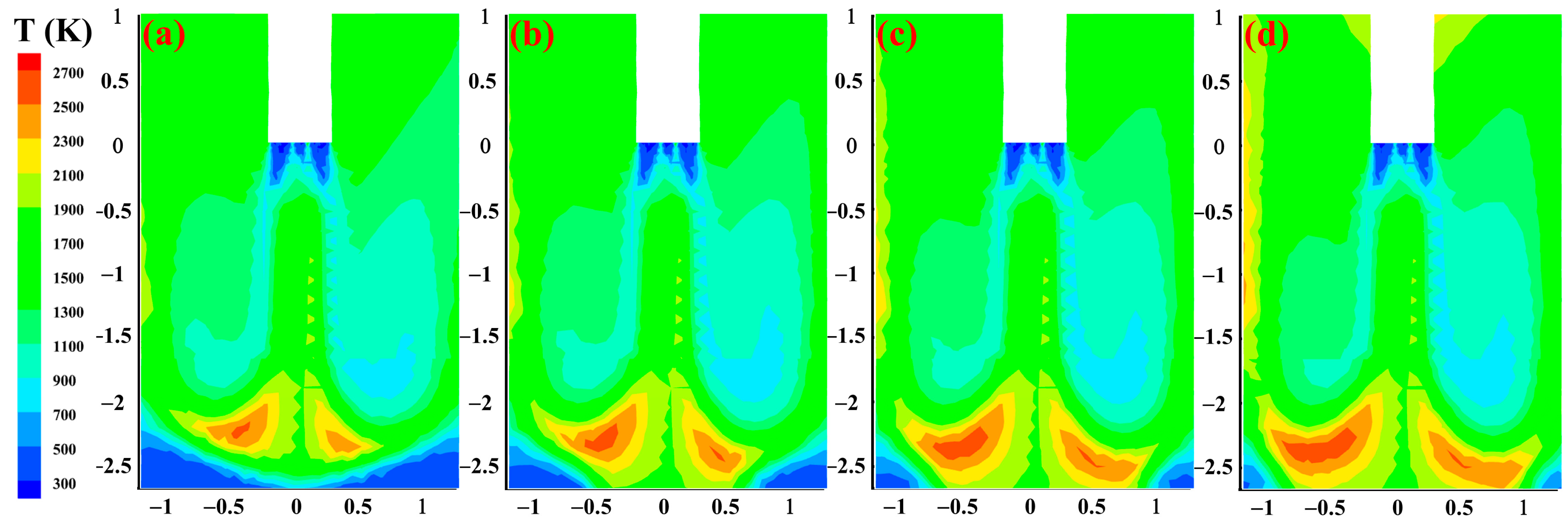
4.1.2. Temperature Field of Hot Metal Ladle

The temperature distribution in the hot metal ladle at different gas flow rates is shown in Figure 5. The E.D. model [40] assumes that most of the gaseous fuel entering the package burns quickly, and combustion can proceed without additional ignition as soon as turbulence occurs. As can be seen from Figure 5, the combustion of gas and oxygen starts as soon as they come into contact with the hot metal ladle, and the initial combustion temperature is low. As the gases continue to mix and burn, the temperature inside the ladle will gradually rise. The temperature distribution of the scrap cross-section at the scrap surface, 1/2 scrap height, and bottom of the scrap are shown in Figure 6. When the gas contacts the scrap surface, a central high-temperature zone is formed at the scrap surface central, and a local high-temperature zone is formed around the ladle wall, as shown in Figure 6a. As the gas enters the scrap interior, the residence time in the scrap zone increases, and the combustion behavior becomes more intense, gradually forming an annular combustion zone (seeing the area between the two solid red lines); the maximum temperature in the zone is about 2500 K, as shown in Figure 6b. By the time the gas moves to the bottom of the scrap, the heat transfer behavior between the gas and the scrap gradually weakens, and a cold zone (seeing the area between the two solid black lines) is formed in the scrap bottom, the temperature in the zone is about 500 K, as shown in Figure 6c. When the gas flow rate increases, there is no significant change in the gas circulation zone, the central high-temperature zone on the surface of the scrap, and the range of the annular high-temperature zone; the internal annular burning zone of the scrap is continuously extended downwards; the range of the cold zone at the bottom of the scrap is continuously reduced.

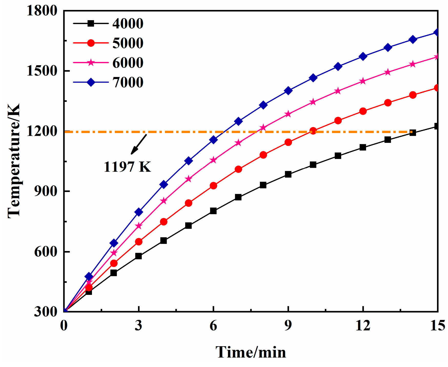
4.1.3. The Effect of Gas Flow Rate on the Average Scrap Pre-Heating Temperature

The studies [41,42] have proved that when the pre-heating temperature is higher than 1197 K, the thickness of the surface oxide layer increases sharply, and the oxidation rate of the scrap increases, which is prone to a serious waste of resources, so the average pre-heating temperature of the scrap should be controlled below 1197 K. The average scrap pre-heating temperature variation curve is shown in Figure 7. The curve is parabolic in shape; with the increase in gas flow rate, the scrap pre-heating temperature up to 1197 K is gradually shortened, and the amount of time reduction gradually decreases. This is consistent with the findings in the review [43]. In addition, the average scrap temperature pre-heating times to 1197 K were 13.89, 9.98, 7.75, and 6.41 min for gas flow rates of 4000, 5000, 6000, and 7000 m3/h, respectively. This is mainly due to the fact that on the one hand, when the gas flow rate increases while the reactants involved in the combustion reaction also increase, then the heat generated by the combustion reaction also continues to increase, while on the other hand [44] the temperature difference between the solid and gas phases decreases as the average temperature of the scrap increases, reducing the heat transfer coefficient between the both.

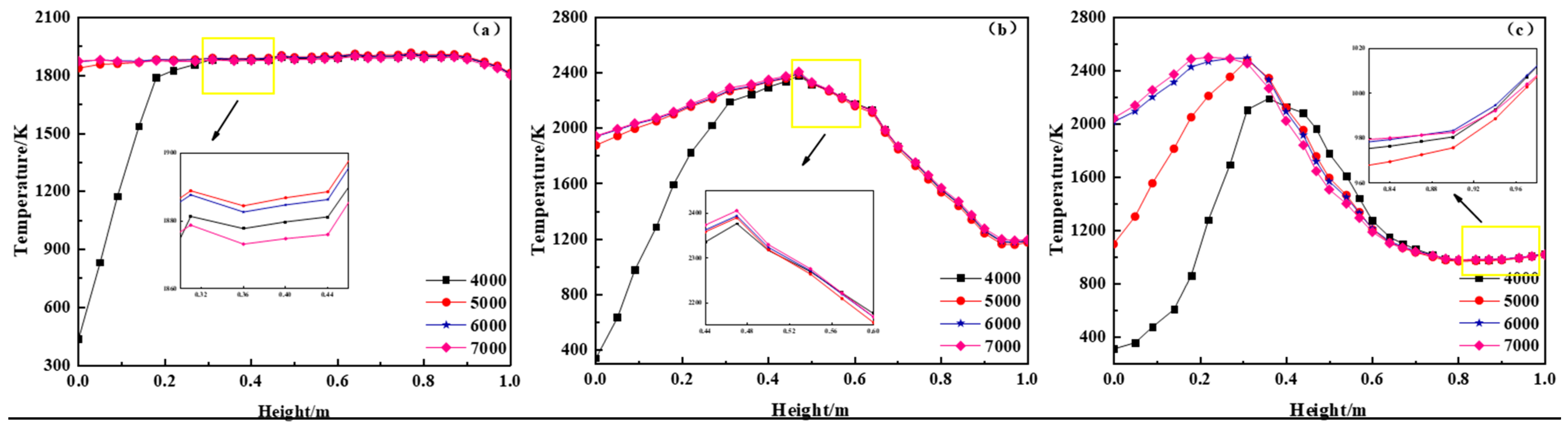
4.1.4. Variation in Scrap Temperature at Different Locations

The scrap temperature variation along the height direction is shown in Figure 8. Figure 8a shows the scrap temperature at different heights at the shaft position. It can be seen that the scrap temperature does not change significantly as the height of the scrap increases and only decreases slightly near the surface of the scrap. When the gas flow rate is 4000 m3/h, the scrap temperature rises continuously with height, and the temperature turning point is located at 0.22 m of scrap height. Figure 8b shows the scrap temperature at different heights at a 1/4 radius. It can be seen that when the scrap height is raised, the scrap temperature rises slowly and then decreases slowly, and the temperature turning point (the temperature at this point is approximately 2400 K) is the same at different flow rates, all located at 0.4 m of scrap height. However, when the gas flow rate is 4000 m3/h, the scrap temperature before the turning point changes more. Figure 8c shows the scrap temperature at different heights at a 1/2 radius. It can be seen that when the scrap height is raised, the scrap temperature rises sharply before decreasing sharply, especially when the gas flow rate is 4000 and 5000 m3/h. This is because the annular combustion zone is located down inside the scrap, and the gas circulation zone crosses the surface of the scrap, resulting in a reduction in the surface temperature of the scrap and an insignificant temperature change in the central airflow zone.
The scrap temperature distribution along the radius is shown in Figure 9. Figure 9a shows the temperature change of the scrap surface. It can be seen that the temperature change of the scrap shows a “W” type trend, which means that the scrap axis position and the position near the wall of the hot metal ladle are higher, with the maximum temperature being 1807 K and 2067 K, respectively. Additionally, the maximum temperature difference is 800 K between the high and low-temperature zones. Figure 9b shows the temperature variation at 1/2 height of the scrap. It can be seen that the scrap temperature distribution shows a trend of “high temperature at the central and low temperature at the ladle wall”, and the temperature at the central fluctuates. Moreover, the increase in gas flow rate leads to higher scrap temperatures in the interval of −1.2 m to −0.4 m and 0.4 m to 1.2 m. Figure 9c shows the change in temperature at the bottom of the scrap. It can be seen that the temperature distribution of the scrap shows a trend of class “n” distribution. The temperature is higher in the middle position and lower at the wall (the highest point position is 0.7 m, and the maximum temperature is 2078 K), but the temperature turning point on both sides of the middle position shifts to the ladle wall with the increase of gas flow, turning point shift from 0.25 m to 0.7 m on the left and from −0.44 m to −0.7 m on the right.
Comprehensive analysis of the effect of different gas flow rates on the temperature field, flow field, and scrap temperature variation during scrap pre-heating. When the gas flow rate increases, the internal annular burning zone of the scrap gradually expands, the cold zone at the bottom of the scrap continues to narrow, and the temperature of the scrap continues to rise. Further comparisons concluded that when the gas flow rate was 5000 m3/h, the annular combustion zone was more evenly distributed, and the cold zone was reasonably sized. The time to reach a pre-heating temperature of 1197 K was 9.98 min.

4.2. The Effect of the Lance Position on Scrap Pre-Heating Temperature

4.2.1. Flow Field of Hot Metal Ladle

The velocity distribution in the hot metal ladle at different lance positions is shown in Figure 10. It can be seen that when the lance position rises, the length of the central airflow zone is gradually extended, and the maximum airflow velocity is also increasing, but the distance between the bottom of this zone and the bottom of the scrap does not change; the gas circulation zone on both sides of the central airflow zone is not symmetrically distributed, and when the lance position is 1378 mm, the area of the gas circulation zone on the right side of the central airflow zone is obviously smaller than the other; the difference between the range of the “dead zone” of the bottom scrap is smaller. The reason for this is that the increase in lance position only raises the height of the gas jet, the height of the scrap does not change, and therefore the distance between the central airflow zone and the bottom of the scrap does not change but instead leads to an increase in the gas circulation zone.

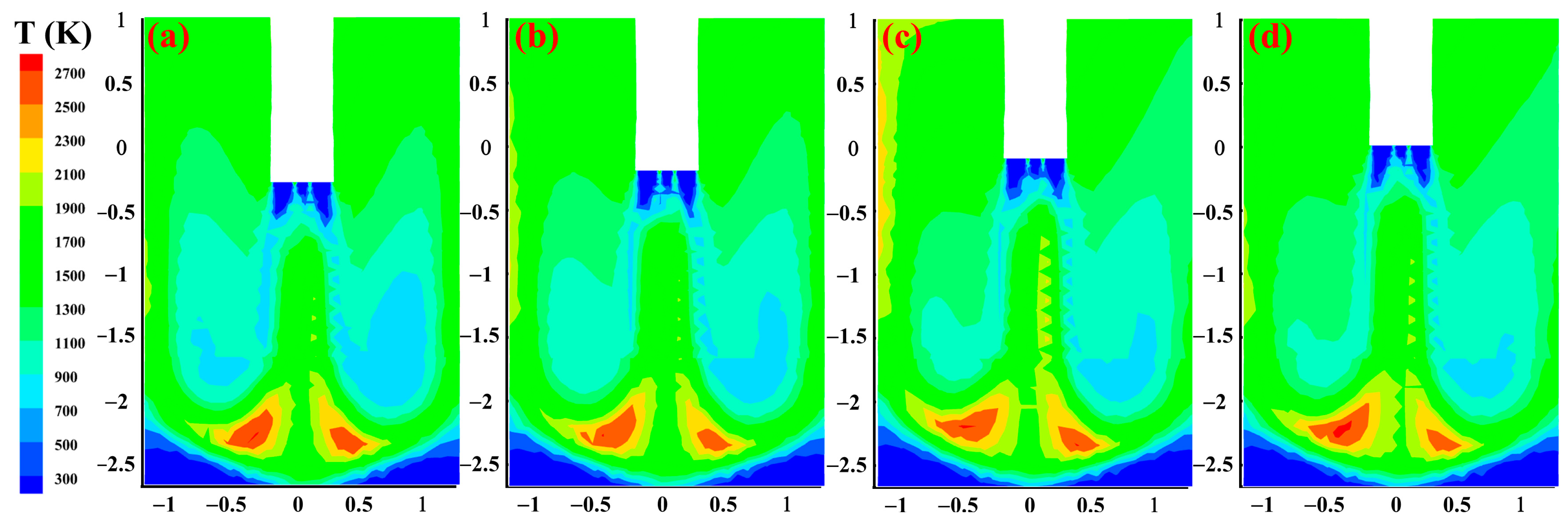
4.2.2. Temperature Field of Hot Metal Ladle

The temperature distribution in the hot metal ladle at different lance positions is shown in Figure 11. The temperature in the scrap zone shows a more obvious asymmetrical distribution with the temperature in the ladle, with the temperature in the left-hand zone being higher. The reason for this is that the negative pressure vent in the lid is located on the right side, which in turn, results in a higher temperature on the left side of the hot metal ladle. The cross-sectional temperature distribution in the scrap zone is shown in Figure 12. As can be seen in Figure 12a, a low-temperature zone appears to the right of the central high-temperature zone, and the extent of the low-temperature zone continues to decrease as the lance position rises. The temperature difference at the 1/2 scrap height is more pronounced, with the central burning annular combustion zone (seeing the area between the two solid red lines) continuing to expand and the low-temperature zone to the right of this area decreasing, as shown in Figure 12b. The “cold zone”(seeing the area between the two solid black lines) at the bottom of the scrap is increasing in extent, as shown in Figure 12c. It can also be seen that the elevation of the lance position has a smaller effect on the temperature difference at the surface and bottom of the scrap and a larger effect on the temperature distribution at the 1/2 scrap height. This is due to the elevated lance position, which directly leads to an extension of the central airflow zone, which in turn leads to an increase in gas mixing time and a significant difference in the annular burning zone within the scrap.

4.2.3. The Effect of the Lance Position on the Average Scrap Pre-Heating Temperature

The average scrap pre-heating temperature variation curve is shown in Figure 13. It can be seen that the overall temperature rise curve is parabolic, with the average scrap temperature decreasing slightly as the oxy-fuel lance position rises. When the pre-heating time is within 5 min, the scrap pre-heating temperatures do not differ significantly from each other. When the pre-heating time is at 9 min, the variability of the scrap pre-heating curves under different lance positions increases, with a maximum difference of 24.82 K; when the pre-heating is at 15 min, variability further increases. It is clear that changes in the oxy-fuel lance position have a small effect on the scrap pre-heating temperature.

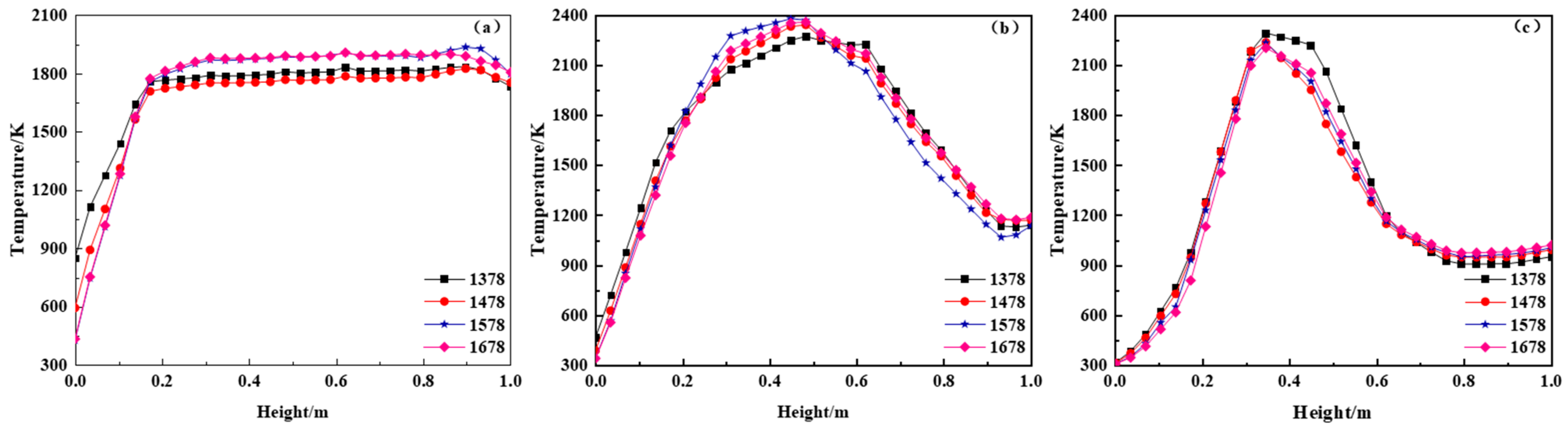
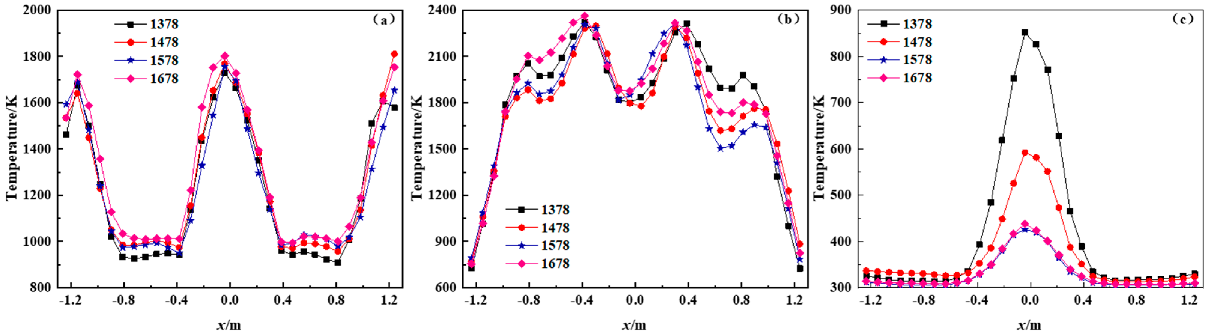
4.2.4. Variation in Scrap Temperature at Different Locations

The variation of the scrap temperature along the height direction is shown in Figure 14. It can be seen that the scrap temperature at the axial position first increases significantly and then fluctuates up and down, with the temperature turn point occurring at the height of 0.16 m. The scrap temperature at the 1/4 radius rises, then falls, and eventually fluctuates slightly, with the temperature turn point occurring at a scrap height of 0.94 m. The scrap temperature at the 1/2 radius rises sharply at first, then slopes down and eventually tends to rise slightly, with the temperature drop occurring at 0.36 m and the temperature rise at 0.79 m.
The variation of the scrap temperature along the radius is shown in Figure 15. It can be seen that the temperature variation at the surface of the scrap shows a “W” pattern; the highest temperatures occurred in the axial position (−0.04 m) and in the wall position (1.24 m), with maximum temperatures of 1802 K and 1808 K, respectively; the temperature variation at 1/2 the height of the scrap shows a trend of “high temperature in the middle and low temperature on both sides”; the temperature variation at the bottom of the scrap shows a trend of “high temperature in the central and low temperature around it”, the central temperature increases from 430 K to 849 K when the lance position is raised from 1378 mm to 1678 mm. The temperature change at the bottom of the scrap has a trend of “high temperature in the central and low temperature around”. The lowering of the lance position helps to improve the cold zone of the scrap at the bottom.
A comprehensive analysis of the effect of different oxy-fuel lance positions on the temperature field, flow field, and scrap pre-heating temperature in the pre-heating process shows that the gas circulation zone is expanded when the lance position is raised. The further comparative analysis concluded that when the lance position is 1378 mm, the temperature field in the scrap area is more evenly distributed, which is more advantageous in improving the bottom scrap cooling zone and increasing the average temperature of the scrap cooling zone.

4.3. The Effect of the Nozzle Angle on Scrap Pre-Heating Temperature

4.3.1. Flow Field of Hot Metal Ladle

The velocity distribution within the hot metal ladle at different nozzle angles is shown in Figure 16. The gas circulation zones on both sides of the central airflow zone (shown as red dashed boxes in Figure 16) show an asymmetrical distribution, and the gas circulation zone on the left is significantly more extensive. The longitudinal depth of the central airflow area is reduced when the nozzle angle is increased, while the lateral distribution expands slightly. The gas circulation zone on the right side of this region continues to decrease, but there is no significant change in the size of the gas circulation zone on the left side. Because when the nozzle angle is increased, it weakens the ability of the gas to impact downwards, causing the gas to diffuse toward the wall of the ladle. The nozzle angle is, therefore, the main factor influencing the flow field in the hot metal ladle.

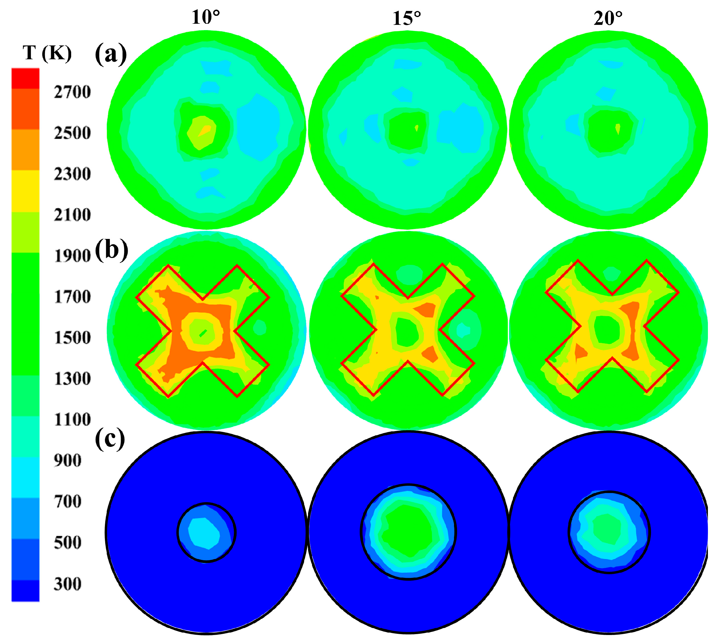
4.3.2. Temperature Field of Hot Metal Ladle

The temperature distribution inside the hot metal ladle at different nozzle angles is shown in Figure 17. It can be seen that the temperature is asymmetrically distributed in the scrap zone, with a significantly higher temperature on the left side of the hot metal ladle. The scrap temperature in the annular burning zone decreases significantly when the nozzle angle is increased, the extent of this zone is continuously reduced, and the bottom cold zone is reduced. The cross-sectional temperature distribution in the scrap area is shown in Figure 18. Figure 18a shows the temperature distribution on the scrap surface. As the nozzle angle increases, the central high-temperature zone continues to decrease, and similarly, the cold zone distributed around it continues to decrease. Figure 18b shows the temperature distribution at 1/2 height of the scrap, where the annular combustion zone changes to an “X” shaped combustion zone (seeing the area between the two solid red lines). This zone is slightly reduced as the nozzle angle increases. Figure 18c shows the temperature distribution at the bottom of the scrap, where the cold zone (seeing the area between the two solid black lines) at the bottom is less extensive when the nozzle angle is 15°.

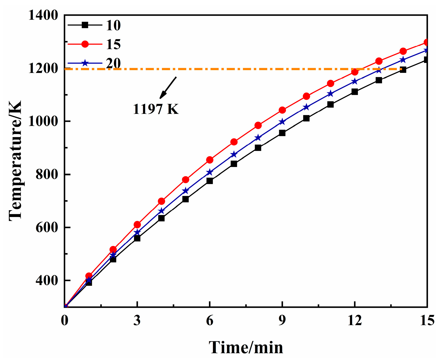
4.3.3. The Effect of the Nozzle Angle on the Average Scrap Pre-Heating Temperature

The average scrap pre-heating temperature variation curve for different oxy-fuel lance nozzle angles is shown in Figure 19. It can be seen that the time taken to reach the average scrap temperature of 1197 K is 13.88, 11.94, and 13.06 min when the nozzle angle is 10°, 15°, and 20°, respectively. The pre-heating time is the shortest when the nozzle angle is 15°. This may be the nozzle angle of 15°, the scrap internal “X” type burning area is more evenly distributed, and the scrap bottom cold area range is the smallest, resulting in the faster pre-heating temperature of scrap. Increasing the nozzle angle can increase the scrap average temperature.

4.3.4. Variation in Scrap Temperature at Different Locations

The distribution of the scrap temperature variation along the height direction is shown in Figure 20. The temperature variation at the center of the scrap shaft (Figure 20a) shows a “rising and then continuously fluctuating” trend, with the temperature turn point occurring at the height of 0.2 m. The turning point temperatures are 1774 K, 1657 K, and 1608 K, respectively. The temperature variation at the 1/4 radius (Figure 20b) follows a “rising then falling” trend, with the point of temperature decline occurring at the height of 0.3 m. The temperature variation at the 1/2 radius (Figure 19c) follows a “rising then falling, eventually fluctuating” trend, with the point of temperature decline occurring at the height of 0.4 m and the point of fluctuation occurring at the height of 0.5 m. The temperature variation at the 1/2 radius (Figure 20c) follows a “rising then falling, eventually fluctuating” trend. The point of temperature decline is at the height of 0.4 m, and the point of fluctuation is at the height of 0.5 m.
The distribution of the scrap temperature variation along the radius is shown in Figure 21. The temperature difference between the scrap surface is obvious (Figure 21a), with a difference of 500 K between the 10° and 15° axis of the spray hole. The temperature at 1/2 scrap height shows a “wavy decline” from the shaft position to the ladle wall position (Figure 21b). The temperature at the center of the shaft is lower than at the sides, with the highest temperatures occurring at −0.3 m and 0.29 m, and the scrap temperature at 0.29 m is slightly higher than at −0.3 m. The temperature at 0.29 m is slightly higher. The temperature variability at the bottom of the scrap is more pronounced (Figure 21c), with the temperature at the bottom axis being significantly higher than in other areas, and the maximum temperature reaches 1053 K at an angle of 15°.
Comprehensive analysis of different nozzle angles on the temperature field, flow field, and scrap pre-heating temperature, when the nozzle angle increases, the gas circulation area range has been reduced, the scrap internal “X” type burning area is slightly reduced, the temperature in this area is significantly lower, the bottom axis of the scrap and the temperature difference between the bottom axis of the scrap and the rest of the zone continues to increase. For further comparison, it was concluded that the gas circulation zone was greatest at the 15° of the nozzle angle and that the combustion zone within the scrap was more evenly distributed, with the shortest time to reach an average temperature of 1197 K.

5. Conclusions

In this paper, a three-dimensional mathematical model of scrap pre-heating is established by means of numerical simulation, and the effects of different gas flow rates, oxy-fuel lance positions, and oxy-fuel lance nozzle angles on the temperature field, flow field, gas distribution, and scrap pre-heating characteristics in the hot metal ladle are systematically studied.
(1)
The rational and correct selection of the gas flow rate has an essential influence on the temperature field, the average temperature in the scrap area. When the gas flow rate increases, the internal annular combustion zone of the scrap gradually expands, the cold zone at the bottom of the scrap continues to reduce, and the average temperature of the scrap keeps increasing. When the gas flow rate is 5000 m3/h, the annular combustion zone is more evenly distributed, the cold zone is more reasonably distributed, and the pre-heating temperature reaches 1197 K in 9.98 min;
(2)
When the oxy-fuel lance position is lowered, the gas circulation zone is reduced, and there is no obvious pattern of change in the internal annular combustion zone of the scrap. When the lance position is 1378 mm, the temperature field in the scrap area is more evenly distributed, which is more advantageous in improving the bottom scrap cooling zone and increasing the average temperature in the scrap cooling zone;
(3)
When the nozzle angle increases, the range of the gas circulation zone is reduced, the temperature of the “X” type combustion zone inside the scrap is obviously reduced, the temperature difference between the bottom axis of the scrap and the surrounding area continues to expand, and the reasonable choice of the nozzle angle is conducive to improving the uniformity of the flow field. When the nozzle angle is 15°, the gas circulation zone is the largest, the temperature distribution in the internal combustion zone of the scrap is better, and the average temperature of the scrap pre-heating reaches 1197 K in the shortest time.

Author Contributions

Conceptualization, S.Z.; methodology, T.W.; software, D.Z.; formal analysis, S.Z.; writing—original draft, S.Z.; writing—review and editing, D.Z. and Y.Y.; visualization, P.L.; resources, Y.Y.; supervision, D.Z. All authors have read and agreed to the published version of the manuscript.

Funding

This research was financially supported by the Open Competition Scientific, Jiangxi Provincial Technical Innovation Guidance Program (20202BDH80002) and Technological Research Projects of Heilongjiang Province (2022ZXJ03A02), and the National Nature Science Foundation of China (51734003).

Data Availability Statement

Not applicable.

Conflicts of Interest

The authors declare no conflict of interest.

References

  1. Jia, Y.Q.; Duan, H.M.; Liu, Q.Y. Scrap steel resource utilization trend in China: Analysis and forecast from 2020 to 2035. China Min. Mag. 2021, 30, 31–36+42. [Google Scholar]
  2. Wang, M.; Gu, S.; Guo, Y. Steel Scrap’s Discovery and Utilization: Based on China. Acta Geol. Sin. Engl. Ed. 2014, 88, 1294–1295. [Google Scholar] [CrossRef]
  3. Futáš, P.; Pribulová, A.; Fedorko, G.; Molnár, V. Influence of steel scrap in the charge on the properties of gray cast iron. ISIJ Int. 2017, 57, 374–379. [Google Scholar] [CrossRef]
  4. Igarashi, Y.; Daigo, I.; Matsuno, Y.; Adachi, J. Estimation of the change in quality of domestic steel production affected by steel scrap exports. ISIJ Int. 2007, 47, 753–757. [Google Scholar] [CrossRef]
  5. Lu, Z.W. A study on the steel scrap resources for steel industry. Acta Metall. Sin. 2000, 7, 728–734. [Google Scholar]
  6. Lu, Z.W. On steel scrap resources for steel industry. Iron Steel 2002, 4, 66–70+6. [Google Scholar]
  7. Oda, J.; Akimoto, K.; Tomoda, T. Long-term global availability of steel scrap. Resour. Conserv. Recycl. 2013, 81, 81–91. [Google Scholar] [CrossRef]
  8. Bailey, D.R.; Onuscheck, J.W.; Oberg, R.K.; Bailey, R.E. High-scrap charge in the BOF utilizing solid fuel. JOM 1967, 19, 96–103. [Google Scholar] [CrossRef]
  9. Voraberger, B.; Wimmer, G.; Salgado, U.D.; Wimmer, E.; Pastucha, K.; Fleischanderl, A. Green LD (BOF) Steelmaking- Reduced CO2 Emissions via Increased Scrap Rate. Metals 2022, 12, 466. [Google Scholar] [CrossRef]
  10. Lu, X.; Bai, H.; Zhao, L.H.; Liu, X.T.; Cang, D.Q. Relationship between the energy consumption and CO2 emission reduction of iron and steel plants. J. Univ. Sci. Technol. Beijing 2012, 34, 1445–1452. [Google Scholar]
  11. Jouhara, H.; Khordehgah, N.; Almahmoud, S.; Delpech, B.; Chauhan, A.; Tassou, S.A. Waste heat recovery technologies and applications. Therm. Sci. Eng. Prog. 2018, 6, 268–289. [Google Scholar] [CrossRef]
  12. Groen, R.G. Scrap Preheating in the Basic Oxygen Furnace at Wisconsin Steel Works. JOM 1966, 18, 478–484. [Google Scholar] [CrossRef]
  13. Hernandez, J.D.; Onofi, L.; Engell, S. Model of an Electric Arc Furnace Oxy-Fuel Burner for dynamic simulations and optimisation purposes. IFAC-PapersOnLine 2019, 52, 30–35. [Google Scholar] [CrossRef]
  14. Onuscheck, J.W.; Holmes, R.L.W. Oxygen and Oil in a BOF. JOM 1972, 24, 26–37. [Google Scholar] [CrossRef]
  15. Entremont, J.C.; Moon, R.E. All-scrap charged BOF. JOM 1969, 21, 53–56. [Google Scholar] [CrossRef]
  16. Chen, Y.C.; Ryan, S.; Silaen, A.K.; Zhou, C.Q. An Investigation into EAF Burner Preheating and Melting Characteristics: CFD Model Development and Experimental Validation. Metall. Mater. Trans. 2023. [CrossRef]
  17. Carlsson, L.S.; Samuelesson, P.B.; Jönsson, P.G. Modeling the Effect of Scrap on the Electrical Energy Consumption of an Electric Arc Furnace. Metals 2020, 8, 1044. [Google Scholar] [CrossRef]
  18. Nugumanov, R.F.; Protopopov, E.V.; Chernyatevich, A.G.; Feoktistov, A.V. Modeling results for the preheating of scrap by means of coal pieces in a converter. Steel Transl. 2011, 41, 301. [Google Scholar] [CrossRef]
  19. Mandal, K.; Irons, G.A. A Study of Scrap Heating by Burners: Part II—Numerical Modeling. Metall. Mater. Trans. B 2013, 44, 196–209. [Google Scholar] [CrossRef]
  20. Honjo, N.; Mori, H. Characteristics of scrap preheating by shaft-type preheater. Denki Seiko Electr. Furn. Steel 1997, 68, 13–20. [Google Scholar] [CrossRef]
  21. Yuan, F.; Wang, H.B.; Zhou, P.L.; Xu, A.J. Combustion performance of nozzles with multiple gas orifices in large ladles for temperature uniformity. J. Iron Steel Res. Int. 2018, 25, 387–397. [Google Scholar] [CrossRef]
  22. Sultan, H.; Muhammad, H.A.; Bhatti, U.H.; Min, G.H.; Baek, I.H.; Baik, Y.J.; Nam, S.C. Reducing the efficiency penalty of carbon dioxide capture and compression process in a natural gas combined cycle power plant by process modification and liquefied natural gas cold energy integration. Energy Convers. Manag. 2021, 244, 114495. [Google Scholar] [CrossRef]
  23. Paramonova, S.; Nehler, T.; Thollander, P. Technological change or process innovation—An empirical study of implemented energy efficiency measures from a Swedish industrial voluntary agreements program. Energy Policy 2021, 156, 112433. [Google Scholar] [CrossRef]
  24. Moya, J.A.; Pardo, N. The potential for improvements in energy efficiency and CO2 emissions in the EU27 iron and steel industry under different payback periods. J. Clean. Prod. 2013, 52, 71–83. [Google Scholar] [CrossRef]
  25. Wachter, P.; Gaber, C.; Raic, J.; Demuth, M.; Hochenauer, C. Experimental investigation on H2S and SO2 sulphur poisoning and regeneration of a commercially available Ni-catalyst during methane tri-reforming. Int. J. Hydrogen Energy 2021, 46, 3437–3452. [Google Scholar] [CrossRef]
  26. Wachter, P.; Gaber, C.; Raic, J.; Demuth, M.; Hochenauer, C. Towards thermochemical recuperation applying combined steam reforming and partial oxidation of methane: Thermodynamic and experimental considerations. Energy Convers. Manag. 2022, 251, 114927. [Google Scholar] [CrossRef]
  27. Wu, B.Y.; Zhai, Y.D.; Shao, L.; Wei, G. Numerical simulation of flow characteristics during scrap preheating in hot metal ladle by oxy-fuel combustion. China Metall. 2021, 31, 17–22. [Google Scholar]
  28. Zou, T.; Zhan, D.P.; Zhuang, S.L.; Jiang, Z.H.; Zhang, H.S. Numerical simulation of oxygen lance injection process. J. Mater. Metall. 2021, 20, 38–44. [Google Scholar]
  29. Veynante, D.; Vervisch, L. Turbulent combustion modeling. Prog. Energy Combust. Sci. 2002, 28, 193–266. [Google Scholar] [CrossRef]
  30. Liu, J.Z.; Chen, S.; Liu, Z.H.; Peng, K.; Zhou, N.; Huang, X.H.; Zhang, T.; Zheng, C.G. Mathematical Modeling of Air– and Oxy–Coal Confined Swirling Flames on Two Extended Eddy-Dissipation Models. Ind. Eng. Chem. Res. 2012, 51, 691–703. [Google Scholar] [CrossRef]
  31. Dodds, J. Particle Packing Characteristics; German, R.M., Ed.; Metal Powder Industries Dederation: Princeton, NJ, USA, 1990; p. 101. [Google Scholar]
  32. Chen, Y.C.; Luo, Q.X.; Ryan, S.; Busa, N.; Silaen, A.K.; Zhou, C.Q. Effect of coherent jet burner on scrap melting in electric arc furnace. Appl. Therm. Eng. 2022, 212, 118596. [Google Scholar] [CrossRef]
  33. Mandal, K.; Irons, G.A. A Study of Scrap Heating by Burners. Part I: Experiments. Metall. Mater. Trans. B 2013, 44, 184–195. [Google Scholar] [CrossRef]
  34. Keramida, E.P.; Liakos, H.H.; Founti, M.A.; Boudouvis, A.G.; Markatos, N.C. Radiative heat transfer in natural gas-fired furnaces. Int. J. Heat Mass Transf. 2000, 43, 1801. [Google Scholar] [CrossRef]
  35. Cheng, P. Linearized theory of two-dimensional radiating gas by a moment method. AIAA J. 1964, 2, 1662–1664. [Google Scholar] [CrossRef]
  36. Xi, X.J.; Yang, S.F.; Li, J.S.; Chen, X.K.; Ye, M.L. Thermal simulation experiments on scrap melting in liquid steel. Ironmak. Steelmak. 2020, 47, 442–448. [Google Scholar] [CrossRef]
  37. Gu, M.Y.; Chen, G.; Liu, X.; Wu, C.; Chu, H. Numerical simulation of slab heating process in a regenerative walking beam reheating furnace. Int. J. Heat Mass Transf. 2014, 76, 405. [Google Scholar] [CrossRef]
  38. Tian, Z.J.; Jin, S.P.; Liu, Z.J.; Huang, S.Y. Experiments of HiTAC furnaces embedded with SCR catalysts for NOx removal. J. Huazhong Univ. Sci. Technol. Nat. Sci. Ed. 2014, 42, 6–11. [Google Scholar]
  39. Rahimi, M.; Amiri, A.; Shabanian, S.R. Experimental study on using hitac technique for synthesis gas production. Chem. Eng. Commun. 2013, 200, 907–918. [Google Scholar] [CrossRef]
  40. Lysenko, D.A.; Ertesv, G.I.S.; Rian, K.E. Numerical Simulation of Non-premixed Turbulent Combustion Using the Eddy Dissipation Concept and Comparing with the Steady Laminar Flamelet Model. Flow Turbul. Combust. 2014, 93, 577–605. [Google Scholar] [CrossRef]
  41. Shi, X.X.; Ju, X.H.; Cai, N. Analysis on oxidation and decarburization of high-carbon chromium bearing steel in heating process. Trans. Mater. Heat Treat. 2017, 38, 139–147. [Google Scholar]
  42. Gao, M.; Gao, J.; Zhang, Y. Simulation on scrap melting behavior and carbon diffusion under natural convection. Int. J. Miner.Metall. Mater. 2021, 28, 380–389. [Google Scholar] [CrossRef]
  43. Wang, W.; Wei, G.; Wang, X. Numerical simulation analysis of the feasibility of preheating scrap in the converter. Steelmaking 2023, 39, 30–34+67. [Google Scholar]
  44. Zhang, L.; Oeters, F. Possibilities of counter-current scrap pre-heating with melting by use of 100% fossil energy. Steel Res. 1999, 70, 296–308. [Google Scholar] [CrossRef]
Figure 1. Schematic diagram of the hot metal ladle: (a) Longitudinal cross-section of the hot metal ladle; (b) Oxy-fuel lance nozzle; (c) Oxy-fuel lance nozzle angle.
Metals 13 00847 g001
Figure 2. Grid division: (a) The hot metal ladle; (b) Oxy-fuel lance nozzle; (c) Hot metal ladle lid; (d) Scrap zone.
Metals 13 00847 g002
Figure 3. Effect of gas consumption per ton of steel on scrap temperature.
Metals 13 00847 g003
Figure 4. Distribution of the flow field at different gas flow rates: (a) 4000 m3/h; (b) 5000 m3/h; (c) 6000 m3/h; (d) 7000 m3/h.
Metals 13 00847 g004
Figure 5. Distribution of the temperature field at different gas flow rates: (a) 4000 m3/h; (b) 5000 m3/h; (c) 6000 m3/h; (d) 7000 m3/h.
Metals 13 00847 g005
Figure 6. Distribution of scrap section temperature at different gas flow rates: (a) scrap surface; (b) 1/2 scrap height; (c) scrap bottom.
Metals 13 00847 g006
Figure 7. Effect of gas flow rate on the scrap average temperature.
Metals 13 00847 g007
Figure 8. Variation of scrap temperature in height direction at different gas flow rates: (a) axial position; (b) 1/4 radius position; (c) 1/2 radius position.
Metals 13 00847 g008
Figure 9. Variation of scrap temperature in radius direction at different gas flow rates: (a) scrap surface; (b) 1/2 scrap height; (c) scrap bottom.
Metals 13 00847 g009
Figure 10. Distribution of the flow field at different lance positions: (a) 1378 mm; (b) 1478 mm; (c) 1578 mm; (d) 1678 mm.
Metals 13 00847 g010
Figure 11. Distribution of the temperature field at different lance positions: (a) 1378 mm; (b) 1478 mm; (c) 1578 mm; (d) 1678 mm.
Metals 13 00847 g011
Figure 12. Temperature distribution of scrap sections at different lance positions: (a) scrap surface; (b) 1/2 scrap height; (c) scrap bottom.
Metals 13 00847 g012
Figure 13. The effect of lance position on the average scrap pre-heating temperature.
Metals 13 00847 g013
Figure 14. Variation of scrap temperature in height direction at different lance positions: (a) axial position; (b) 1/4 radius position; (c) 1/2 radius position.
Metals 13 00847 g014
Figure 15. Variation of scrap temperature in radius direction at different lance positions: (a) scrap surface; (b) 1/2 scrap height; (c) Scrap bottom.
Metals 13 00847 g015
Figure 16. Distribution of the flow field for different nozzle angles: (a) 10°; (b) 15°; (c) 20°.
Metals 13 00847 g016
Figure 17. Distribution of the temperature field for different nozzle angles: (a) 10°; (b) 15°; (c) 20°.
Metals 13 00847 g017
Figure 18. The temperature distribution of the scrap cross-section for different nozzle angles: (a) scrap surface; (b) 1/2 scrap height; (c) Scrap bottom.
Metals 13 00847 g018
Figure 19. The effect of the nozzle angle on the average scrap pre-heating temperature.
Metals 13 00847 g019
Figure 20. Variation of scrap temperature in the direction of height at different nozzle angles: (a) axial position; (b) 1/4 radius position; (c) 1/2 radius position.
Metals 13 00847 g020
Figure 21. Variation of scrap temperature in the direction of the radius of the nozzle angles: (a) scrap surface; (b) 1/2 scrap height; (c) scrap bottom.
Metals 13 00847 g021
Table 1. Simulation scheme.
StageGas Flow /(m³·h−1)Lance Positions/mmAngle/°
Stage 1400013780Case1
5000Case2
6000Case3
7000Case4
Stage 2500013780Case5
1478Case6
1578Case7
1678Case8
Stage 35000137810Case9
Table 2. Gas compositions (wt./%).
COCO2O2N2H2
Mass fraction34.8417.530.6745.731.10
Disclaimer/Publisher’s Note: The statements, opinions and data contained in all publications are solely those of the individual author(s) and contributor(s) and not of MDPI and/or the editor(s). MDPI and/or the editor(s) disclaim responsibility for any injury to people or property resulting from any ideas, methods, instructions or products referred to in the content.

