Article

Potential of Integrated Component-Driven Material Design to Improve Crash Box Performance

by
Nima Jafarzadeh-Aghdam
1,2,*,
Yannik Sparrer
3,
Jannik Zimmermann
1,
Konrad Arno Gregor Mäde
4,
Rahul Sharma
4,
Kai-Uwe Schröder
1 and
Sebastian Münstermann
3
1
Institute of Structural Mechanics and Lightweight Design (SLA), RWTH Aachen University, 52062 Aachen, Germany
2
Electric Powertrain Department, FEV Europe GmbH, 52078 Aachen, Germany
3
Integrity of Materials and Structures (IMS), Department of Ferrous Metallurgy (IEHK), RWTH Aachen University, 52072 Aachen, Germany
4
Welding and Joining Institute (ISF), RWTH Aachen University, 52062 Aachen, Germany
*
Author to whom correspondence should be addressed.
Metals 2023, 13(5), 915; https://doi.org/10.3390/met13050915
Submission received: 27 March 2023 / Revised: 24 April 2023 / Accepted: 25 April 2023 / Published: 8 May 2023

Abstract

:
The crushing of crash boxes is a complex phenomenon characterized by a strong interaction of structural and material properties. Many attempts to improve their energy absorption by adopting one aspect resulted in unacceptable unprogressive bucking. Thus, special considerations are required for crash box optimization including both material and structural effects. In this study, the structural behavior of the crash box is analyzed and a new design approach is introduced to fulfill these requirements. Currently, components, processes, and materials are mainly developed independently. However, to exploit the full potential of modern materials in component design, integrative development work is necessary. Component performance-based requirements and corresponding local material properties must be taken into account concurrently. In this work, a component-driven material design approach is presented, in which local-material-property requirements are derived from component simulations. This new approach is demonstrated by the use case of a quasistatically deformed crash box produced out of steel DP600 for the optimization target “energy absorption”. The finite element simulations were carried out on the crash box, and required material properties for improving the crash box performance were derived based on the simulations. Heat treatment strategies were developed afterwards and experimentally validated to fulfill these requirements. The finite element (FE) simulations based on the experimentally extracted material properties reveal the potential of the component-driven material design approach to improve the crash box performance. The introduced approach enables exploiting the full energy-absorption capacity of the material while ensuring the desired service behavior of the component.

1. Introduction

Crash boxes are thin-walled tubes, which are used widely for energy-absorption purposes in collisions. In crash boxes, the kinetic energy of an impactor is converted by continuous folding into plastic deformation. To employ the full potential of a crash box, its material and structural aspects shall be considered simultaneously.
In the past decades, a considerable amount of research was conducted on the structural behaviors of crash boxes. Several approaches have been introduced for estimating and improving their energy absorption [1,2,3]. Progressive buckling is a prerequisite for the crash box function. The buckling of a tube is progressive when it produces several local folds (wrinkles) along the structures under axial loading. The progressive buckling of crash boxes has been studied in several research works [4,5,6,7,8]. The crash box peak force is another important aspect of a crash box design. Axial crushing of thin-walled tubes leads to a high initial peak force, which is related to the first fold creation on the tube. A high peak force endangers protected structures and passengers’ safety [9]. Apart from the mentioned aspects, cracking in corners [10] and global-stability failure [4,8] of the component should also be considered in the crash box design. Small cracks do not endanger the progressive buckling of the crash box; however, the production of large cracks shall be prevented. Comprehensive books and review papers have been published on crash box analysis [11,12,13,14,15]. Even though a considerable amount of research has been devoted to crash boxes, they require constant improvements due to the demand for increasing passengers’ safety and lightweight design concerns.
Different studies have been conducted to improve crash box performance. Materials optimization and also foam filling effects were studied in [16,17,18,19]. It is reported that the foam filling can enhance energy absorption, even though the exact response of the cellular material to dynamic loading is not yet comprehensively understood. Wang et al. used a multiobjective optimization approach in combination with a biomimetic-inspired lattice filling of the crash box to improve its crashworthiness [20]. Besides the material approaches, geometrical approaches are also widely used to improve energy absorption. Jones et al. studied the effect of stiffening elements on crash box efficiency [21]. The stiffeners were joined to the inner and outer surface of the crash box to increase the crash box energy absorption. Even though the energy absorption increased, the stiffeners also increased the chance of crash box global buckling. The external linear-gradient grooves’ effect on the crashworthiness of the circular tubes was studied by Yao et al. [22]. The crashworthiness design of the windowed tubes under axial loading was studied by Nikkhah et al. [23]. Multicell tubes as a replacement for typical tubes have been studied in several research papers [13,18,24,25]. The studies revealed that increasing the number of the corners results in an energy-absorption raise. Thickness grading and corrugating effects on the multicell tube performance have been studied by Fang et al [26] and Li et al. [27]. Zhang et al. have studied the thickness grading effect on energy absorption of hollow square tubes [28]. They reported that the grading can increase the energy absorption up to 30% without increasing the crash box peak force. This thickness grading can be achieved by different process strategies [29], e.g., flexible rolling, which is used to produce tailor-rolled blanks [30], or adapted welding processes to manufacture tailor-welded blanks [31]. The crash box manufacturing itself was investigated by Dimirci et al. who characterized the influence of spot welding in crash box assembly regarding its performance [32]. This summary shows that many research efforts were invested to understand the structural mechanisms of crash box folding. However, all these studies lack a comprehensive consideration of material-related effects.
A first attempt to incorporate material effects has been introduced in the literature to improve crash box performance using local heat treatment. Bambach et al. [33] have used laser heat treatment to obtain spatially graded components to control the folding patterns of crash boxes. By applying the same crush energy, the crushing distance of the crash box decreased almost by 28% due to the strain-hardening engineering. Similar results were reported by Quadfasel et al. who also used strain-hardening engineering to enhance the material properties and, thus, the crash box efficiency [34]. The optimization resulted in a 35% weight reduction in the crash box. Conrads et al. [35] have used local heat treatment to increase the energy absorption capacity of the crash box and also to increase ductility at the corners of the steel crash box to prevent crack initiation. Based on their results, the locally heat-treated crash box in comparison to the fully recrystallized crash box can absorb the same amount of energy with 17% less crushing distance. Contrary to the laser heat source, which has been used by Bambach et al. [33], Hosseini et al. used an arc heat treatment technique to produce graded microstructures through controlled temperature gradients [36]. Several studies have reported the high effect of the local manipulation of the material properties on the energy absorption of crash boxes [26,28,37]. A comprehensive review of different approaches to improve crash-box performance is provided in [13]. The conducted studies have mainly focused on the energy absorption of the crash boxes. However, changes in the structural behavior such as the progressive buckling shall also be considered, which is a prerequisite for the crash box performance. Due to the constraints between different crushing features of the crash box, simultaneous improvement of them is quite a challenging task.
Most of the existing design and optimization approaches of the thin-walled crash box can be categorized into geometrical-based, material-based, and process-based approaches. Usually, if a novel steel alloy is developed its application on the crash box is investigated regarding the energy absorption. The same applies if a heat treatment method or forming process is refined. Whereas in this paper, an integrative method is established, which can be seen as an improvement of the current component design: from a material-focused structural design approach to a component performance-based material development. This allows the identification of component-derived local property requirements, which are converted into tailored material properties. Similar concepts can be found in the literature. Ituarte et al. [38] developed a functional graded material design and manufacturing workflow which included problem specification, graded structural design, grading realization, and product fabrication. This work focused on additively manufactured structures of so-called digital materials. Comparable approaches of fully integrated design workflows can be found in the field of aminated continuous fiber-reinforced composites [39]. In this context, local property grading for nodular cast iron has been studied by Gebhardt et al. [40] and Ripplinger et al. [41]. Both works showed a benefit in terms of increased fatigue strength in the case of high silicone-alloyed nodular cast iron and ferrite-graded nodular cast iron. Even though the approach shows high efficiency, it has not been applied to dual-phase steel, nor to crash relevant structural automotive components, to the best of the authors’ knowledge.
The most important challenge in crash box optimization is increasing the energy absorption and simultaneously minding its crushing features such as its progressive buckling, peak force, crack initiations, etc. The complex coupling between the material and structural effect makes this topic challenging. Therefore, requirements from both material and structural aspects shall be considered in the optimization approaches. The introduced approach of the current study can fulfill both requirements and it consists of three steps:
  • Understanding the structural behavior and affecting parameters;
  • Extracting the material requirements;
  • Designing the material accordingly to fulfill these requirements.
The introduced approach of this study enables the production of optimized structures.
Regarding the material requirements, higher material strength can result in higher energy absorption. On the other hand, an increase in the strength of material results in ductility reduction. Therefore, conventional approaches of material selection for crash box application suffer from the required compromise of fulfilling all requirements at the same time, even though typically the highest strength and the highest ductility are not required in the same spot. Our new approach will be demonstrated based on the compromise between strength and ductility. Noteworthily, additional features, e.g., damage initiation resistance, could be also considered in our framework. However, for the purpose of demonstration, our focus will remain on strength ductility. With our approach, we demonstrate how to increase energy absorption and prevent the creation of large cracks on the crash box. On the other hand, it maintains the progressive buckling of the crash box, which is necessitated by the structural requirements. This special feature of the introduced approach is due to the freedom that resulted from designing the material based on the component requirements.
In this paper, the above-mentioned approach of component-driven material design is demonstrated on property-graded crash boxes. Here, the energy absorption is taken as the measure for the assessment of the crash box performance, but the structural behavior is considered as well. The aim is to increase the energy absorption without endangering the progressive buckling of the crash box by the local adjustment of material properties. Therefore, a proper local adjustment of the material properties was defined by analyzing the crushing behavior of the crash box. Using finite element models, artificial material cards were assigned locally in order to optimize the energy absorption of the crash box. With this approach, local property requirements were defined. Isothermal heat-treatment investigations were used afterwards to determine information regarding holding time and temperature that allows the fulfillment of the previously identified mechanical property requirements for the steel used in the crash box. Furthermore, finite element analysis was used to investigate the crushing behavior of the crash boxes, and thereby, the effects of different material behaviors on crash box features such as peak force were studied. Subsequently, finite element analysis was implemented to identify the advantages of local grading over the homogenous heat treatment of the entire crash box regarding its progressive-buckling behavior. In comparison to previous studies, the current work contains the following novelties:
  • Implementing a new design approach, from a material-focused structural design approach to a component-performance-based material and process development;
  • Identification of component-derived local property requirements, which can be converted into tailored material properties;
  • Analyzing the crushing behavior of square crash boxes in order to improve its energy absorption and retain its progressive buckling;
  • Definition of advantages and limitations of property-graded crash boxes.

2. Materials and Methods

2.1. Material

In this study, a cold-rolled DP600 steel with a material thickness of 1.5 mm was investigated. This plate was produced by Thyssenkrupp in Essen, Germany. The chemical composition of the material is displayed in Table 1. As part of the 2nd Gen. Advanced High Strength Steels (AHSS), dual-phase (DP) steels are characterized by their good combination of strength and ductility, which makes them attractive for crash components in the automotive industry. This mechanical property profile of DP steels is attributed to the ferritic–martensitic microstructure. Depending on the hard to soft phase ratio the mechanical properties can be designed. The investigated DP600 steel features a microstructure containing around 10% martensite and 90% ferrite.
Tensile properties of the DP600 steel were determined following the standard DIN EN ISO 6892-1 using a tensile specimen with a gauge length of 20 mm. According to the tensile test, a yield strength (YS) of 391 MPa, ultimate tensile strength (UTS) of 705 MPa, and total elongation (TE) of 31.3% were extracted. The stress–strain curve and the microstructure of the DP600 are shown in Figure 1.

2.2. Identification of Local Property Requirements Using a Component-Driven Material Design Approach

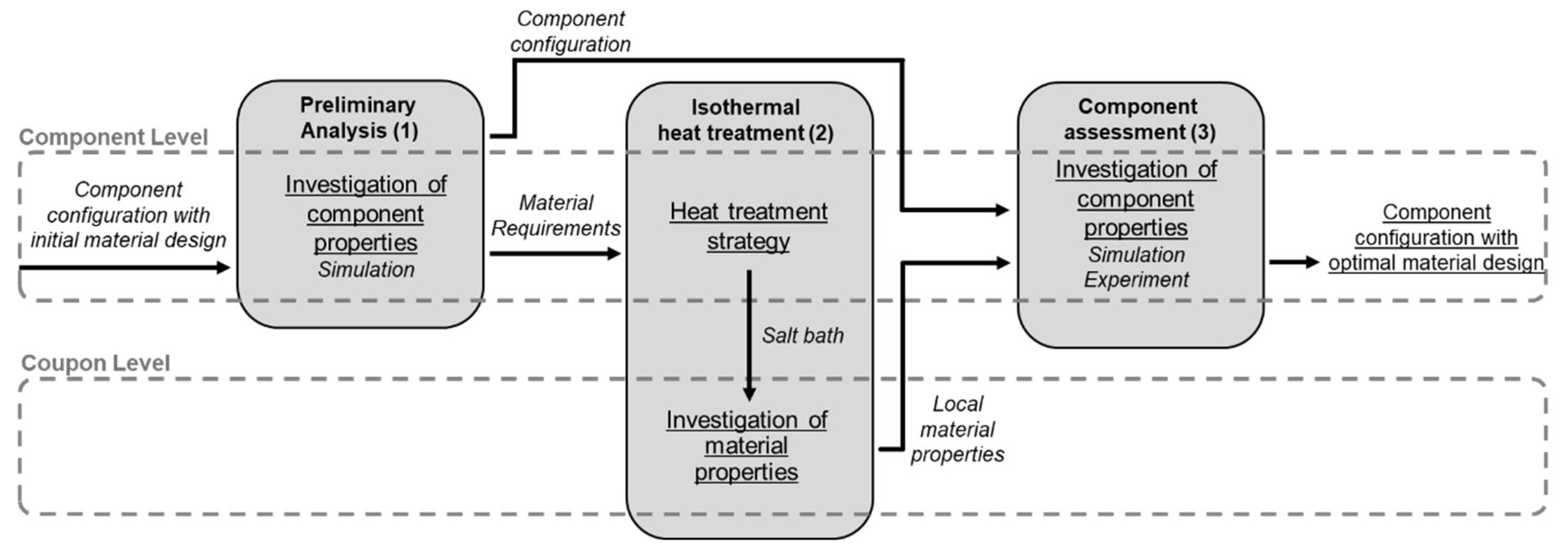
In the present work, a novel methodical approach for integrative material, process, and component design is presented and applied on crash boxes. This approach aims to demonstrate the potential of a component-driven material design in order to increase the energy absorption potential of a crash box. Unlike conventional component design, where global homogenous material properties are defined, this approach first derives required local material properties on the component level using a preliminary analysis that combines FEM simulations with artificial material cards and analytical progressive buckling conditions [42,43] (see step 1 in Figure 2). Hereby, the primary optimization target is to maximize the energy absorption of the crash box. Furthermore, several additional constraints are considered. First, the buckling of the crash box should be progressive, which can be assured by the requirement in terms of local yield stress. Additionally, the local property requirements should take the resulting peak force of the crash box into account. Thus, the difference between the peak force and average crushing force should be minimized to provide a smooth energy absorption process. The experimental fulfillment of these material requirements within the constraints of the applied process technology (e.g., short holding times) is investigated using selected, isothermal heat treatments of the base material DP600 in a salt bath. The following material characterization, including microstructural and mechanical investigations, enables the identification of functional relationships between the heat-treatment process parameters and resulting mechanical properties (2). Based on these results, further FE simulations were carried out to assess the performance of heat-treated crash boxes (3). A schematic process map of the component-driven material design approach is shown in Figure 2.

2.3. Crash Boxes under Axial Loading

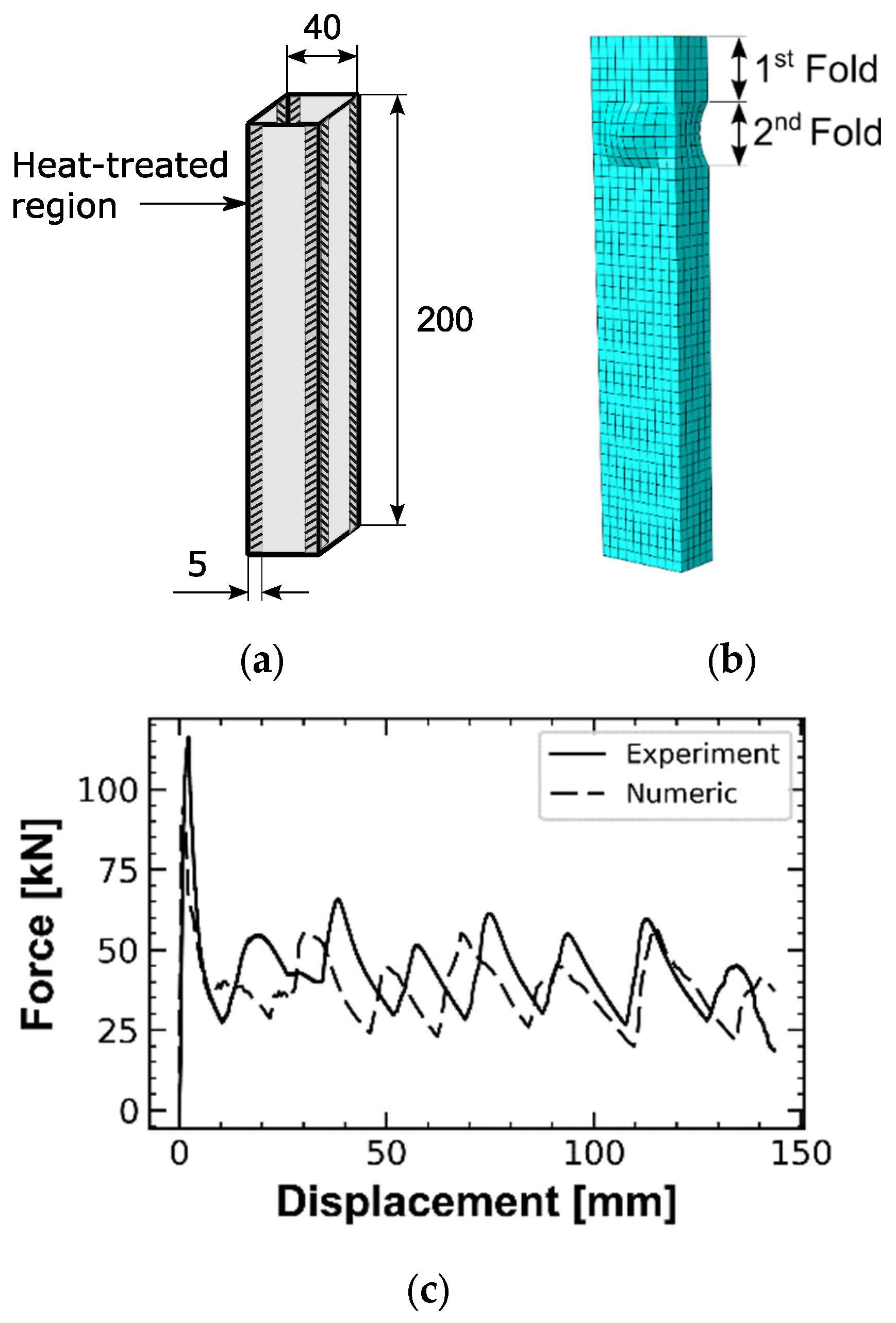
To carry out and validate the abovementioned method, both experimental and numerical compression tests on crash boxes are required. The experimental data is afterward taken to validate the simulation model. These tests were used as a basis for formulating local-material-property requirements to improve the component performance. The crash box specimen was manufactured from DP600 steel, which was characterized in Section 2.1. The crash box was manufactured by arc welding of two u-shape profiles, which were bent from the DP600 steel sheets. Thus, the weld seams were located in the middle of the side faces. Dimensions of the manufactured crash box were 40 mm × 40 mm × 200 mm and the thickness was 1.5 mm.
Even though the normal function of the crash boxes is under dynamic loadings, such as collisions, it is enlightening to first investigate the crash box behavior under a quasistatic load. Moreover, most of the vehicle collisions are in low velocities, about 40 m/s at most, and the influence of the stress-wave speed on the crash box behavior during an impact weakens as the impact velocity decreases [44]. Therefore, it is quite a common simplification to analyze the crushing behavior of the tubes under quasistatic loads [12]. For a more precise analysis, the strain-rate effects shall be considered. However, as the aim of the current study is to introduce a new design methodology, quasistatic loading was considered for the FE simulations and experiments.
The specimen was painted with a stochastic pattern to investigate the local strains by aid of digital image correlation (DIC), and the measuring system Aramis 4M manufactured by GOM was used for this purpose. The mechanical tests of the investigated crash box was performed using a servo-hydraulic testing machine, Instron 8804. The sampling frequency was set at 100 Hz. The force signal was correlated with DIC data (sampling frequency of 4 Hz) to extract local strains at certain load points of interest during the test. The compression load was applied via a load stamp with a displacement rate of 30 mm/min until the crash box is bottomed out. The experimental setup is shown in Figure 3.
The numerical simulations of the crash boxes were performed using Abaqus commercial software (version 2017). By considering the symmetry of the crash box and also the symmetry of its crushed form, half of the crash box was simulated. The particular design of the crash box ensures its symmetric folding pattern [45]. Four-node doubly-curved shell elements with full integration were used to mesh the crash box. By performing a mesh convergence study, a 1.25 mm mesh size was chosen for the meshing. On the tested crash boxes, no imperfections were made deliberately; however, the production phase could not be perfect. Therefore, implementing a small imperfection on the FE model can result in more realistic results [46]. Thus, a small imperfection with 0.1 mm deflection was applied to the second fold region of the crash box (see Figure 4b). The fold region can be located by calculating the fold length of the crash box, as a progressively buckled crash box has a specific fold length. The fold length means the length of the crash box that contributes to a local fold creation and it can be extracted analytically or experimentally, by dividing the crash box length by the number of the folds produced along it [17,45,47,48]. The material card of the DP600 steel was applied to the model. The flow curve was derived from the previously discussed quasistatic tensile tests of the DP600 steel. The equivalent plastic strain value in the simulated crash box can go beyond the strain at the necking point extracted by the one-dimensional tensile test [49]. Thus, the extracted flow curve was extrapolated using the Voce hardening function,
σ y ε p = K 0 + Q 1 e b ε p ,
where σy(εp) donates the stress as a function of plastic strain, K0 and Q are material constants, and b is the strain hardening exponent, which were extracted experimentally, based on the tensile test results (see Table 2).
The explicit integration method can be used for low-speed quasistatic simulations [50]. To reduce the calculation time, it is often useful to use mass scaling or reduce the analysis time. Both approaches yield similar results for the rate-independent models [51]. The analysis time of 0.3 s and mass-scaling factor of 4 were considered for the analysis. Even though mass scaling and analysis-time reduction are common approaches to decrease computation time, attention should be applied as they can affect the accuracy of the results [46,52]. Therefore, the FE results should be analyzed to be sure about the accuracy of the model. The calculated kinetic energy was insignificant compared to the energy absorbed by the specimen and the load-displacement diagram was not affected remarkably. Furthermore, in order to ensure the simulation accuracy, the model is validated using the experimental results.
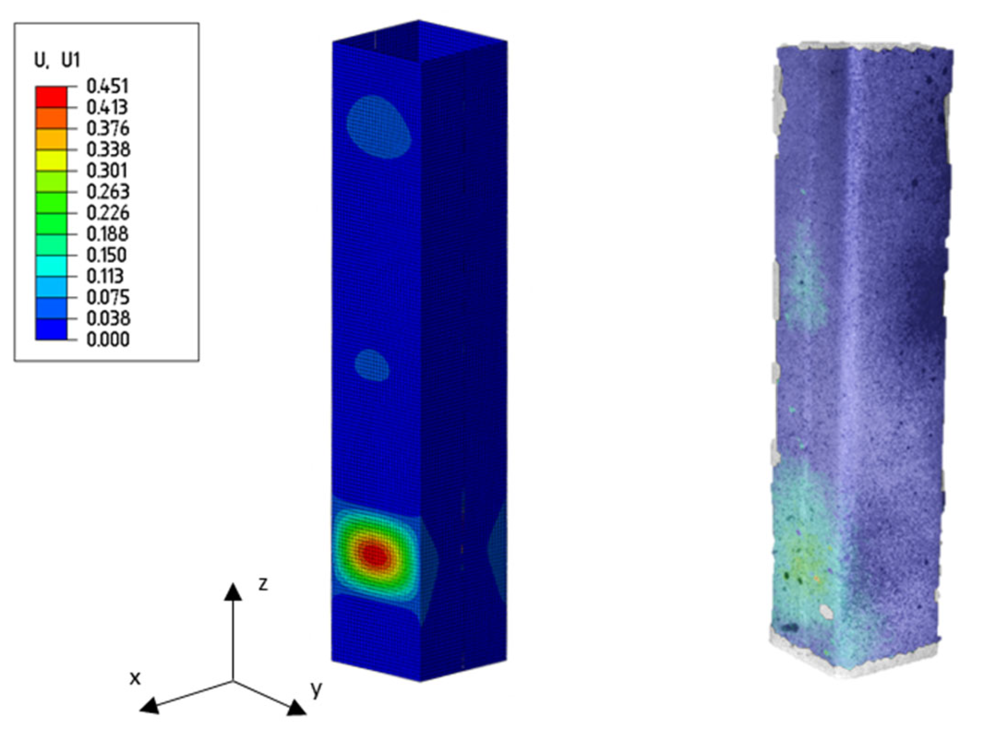
Validating the FE model is crucial in a crash box simulation. FE and experimental results of the compression test on the none heat-treated crash box are presented in Figure 4c. Furthermore, Figure 5 shows the comparison of the out-of-plane displacement, in the x-direction, between the FE analysis and the experiment at the peak force moment, captured using the DIC method. The extracted peak force is 116 KN (see Figure 4c); this peak force is related to the first fold creation on the tube. The first fold is located at the bottom end of the crash box, both in the FE and the experiment. Furthermore, two pre-folds are emerging as well, in the middle and at the top edge of the crash box. Considering the crash box crushed shape and force–displacement diagrams, overall, a good agreement could be obtained between the FE model and the experiment. As can be seen in Figure 6, the corners of the crash box face the highest strain. Therefore, increasing the strength and ductility of the corners’ region can improve the energy absorption, which is going to be discussed more in detail in the result section.
The energy absorption of the crash box is defined as the area under the force–displacement curve derived from a component test. The energy absorption E (kJ) can be calculated as
E = F δ d δ ,
where F represents the force and δ represents the displacement.

2.4. Progressive Buckling and Corner-Strengthening of a Crash Box

Progressive buckling is a prerequisite for the crash box function. Progressive buckling develops local folds along the crash box length. These local folds result in plastic deformation of considerable regions of the crash box and a high amount of energy absorption. This plastic deformation is the main energy-absorption mechanism of a crash box. Progressive buckling is also called stable deformation under axial loading. A crash box has progressive buckling when its plates buckle plastically [6,42,43]. A crash box can be considered as four connected plates, and the critical buckling stress of a plate can be calculated as
σ c r = k π 2 E 12 1 υ 2 t b 2 ,
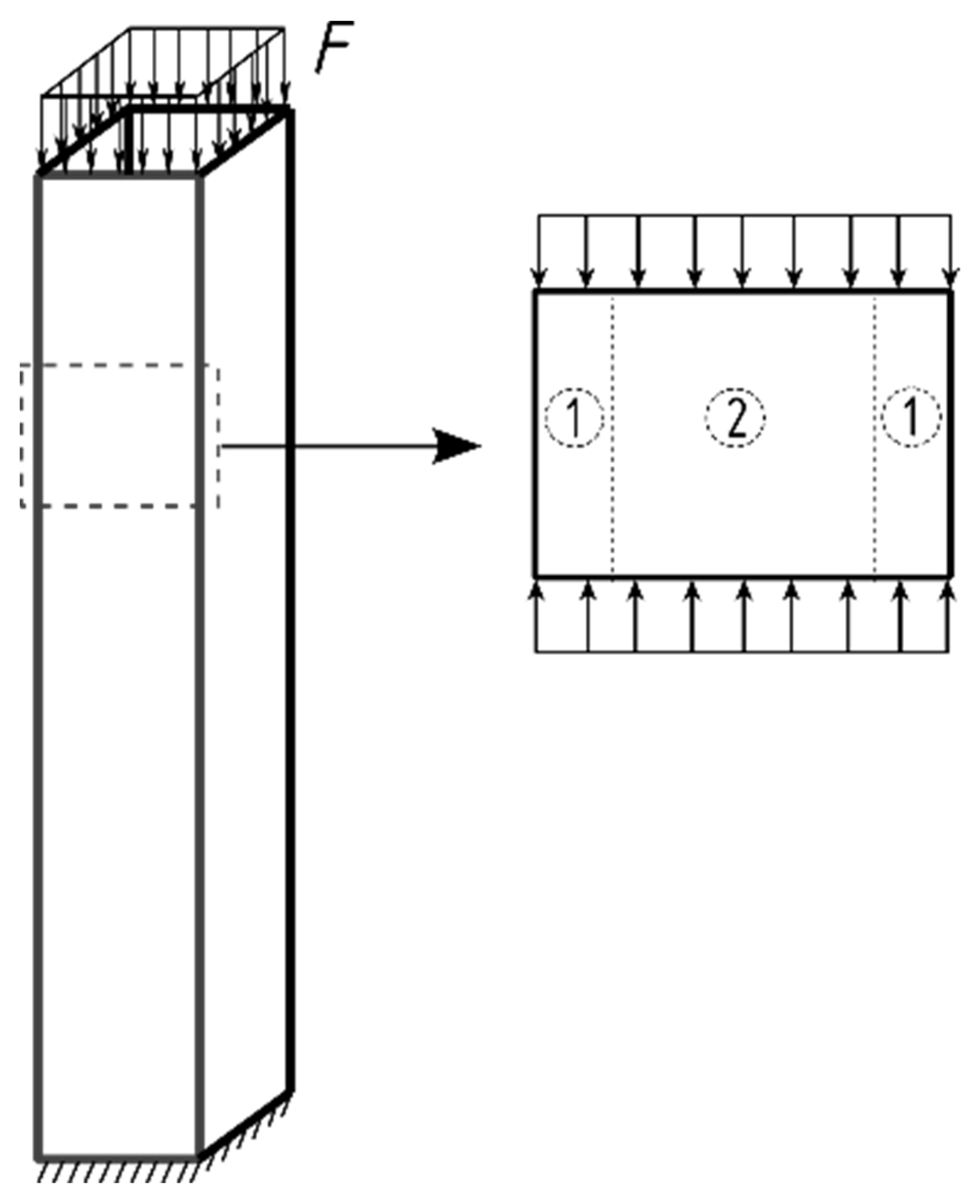
where E is the Young modulus, υ is Poisson’s ratio, k is the buckling coefficient, b is the width, and t is the thickness of the plate, respectively [53,54]. Based on the dimensions of the plates, the boundary condition of the crash box plates was assumed to be simply supported [55]. Besides the plastic buckling necessity, it was shown in [6] that a crash box cannot buckle progressively when the length of the local folds is higher than the crash box width. Therefore, the maximum length of a plate that contributes to a local fold production is the same as the crash box width, see Figure 7. In order to have plastic buckling, the critical buckling stress of this plate should be beyond the yield stress of the material, σ Y S < σ c r . This is a necessary condition for the crash box to buckle progressively [6,42,43] as the sharp decrease in the stiffness after the yield stress enables the production of a regular folding pattern in the crash box.
In order to provide a reliable approach to improve the energy absorption of a crash box a deep understanding of its crushing behavior is required. Applying a heat treatment to increase the ultimate strength of crash box material normally increases its yield stress as well. This increase can result in elastic buckling and, consequently, the unprogressive buckling of the crash box, as it violates the necessary condition given above. However, by analyzing the crushing behavior and applying only local heat treatments instead of the global one a better performance can be achieved. By applying a compression load on the crash box, the midregions of its plates buckle and then stress transfers to the sides of the plates [48], as seen in Figure 7. The side regions can withstand more load due to the higher rigidity caused by the crash box corners [56,57]. By further increasing the load the side regions buckle as well, which, consequently, results in a local fold production on the crash box [48]. As was mentioned, the mid and side regions shall buckle plastically to have a progressive buckling. By considering the higher buckling stress at the side regions, higher yield stress at these regions is acceptable compared to the yield stress at the midregion. With the aid of the component-driven material design approach and local heat treatment, the material properties at the mid- and side regions can be designed independently in order to improve the energy absorption capacity of the crash box and retain its progressive buckling behavior. It should also be considered that a progressive buckling and production of the local folds results in the creation of sharp curves and high plastic deformation at the side regions. Therefore, increasing the strength at these regions, i.e., crash box corners, improves the energy absorption considerably. However, the sharp curves require also a minimum ductility in these regions to prevent large crack production.

2.5. Heat Treatments and Characterization Methods

The heat treatments to examine suitable strategies to fulfill property requirements were carried out in a salt bath. The material was isothermally heat-treated for one minute at a specific holding temperature, which ranged from 750 °C to 950 °C, before quenching in oil. These heat treatments lead to partial or complete austenitization before quenching, so that microstructural configuration is significantly different from the initial state. For microstructural characterization of the different heat treatment states, the samples were etched with Nital after metallographic preparation. The mechanical properties were determined using the Vickers hardness test and quasistatic tensile test according to DIN EN ISO 6892-1.

3. Results and Discussion

3.1. Energy Absorption of a Corner-Strengthened Crash Box

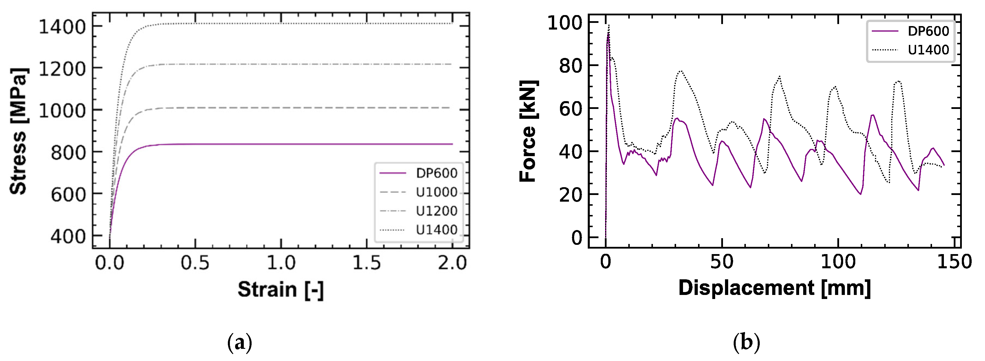
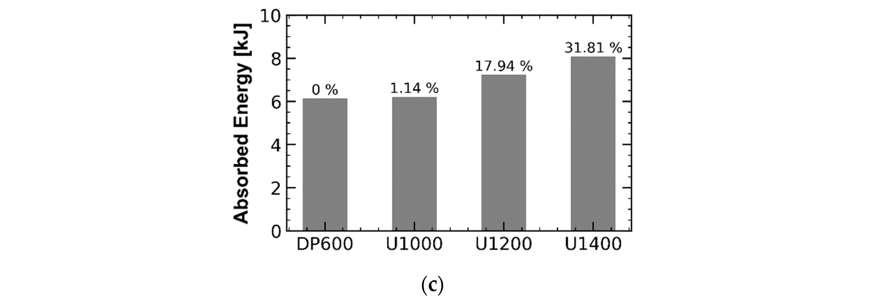
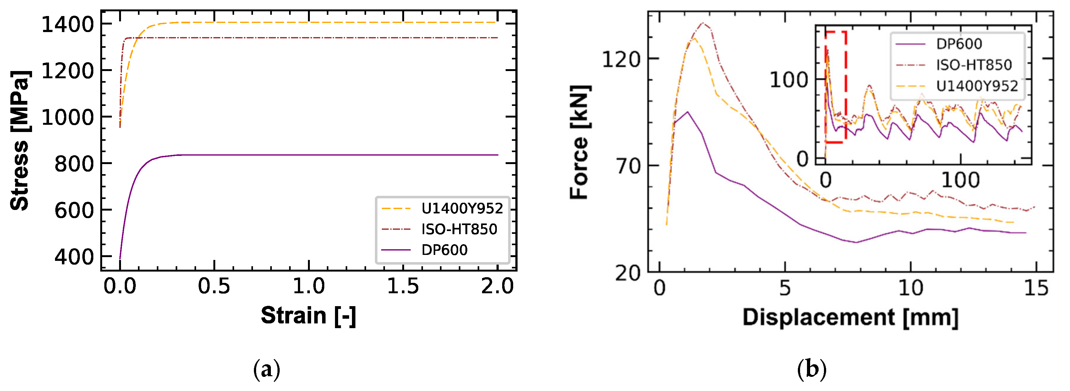
The FE-analysis results of the corner-strengthened crash box are provided in this section. As was discussed, local strengthening of the crash box corners can improve the crash box energy absorption. Even though this local strengthening normally results as well in the yield stress increase, it remains locally. Therefore, this local strengthening can still ensure a progressive-buckling behavior in the crash box, which is going to be discussed more in detail in the next sections. A parametric study was conducted and different material cards were applied to the crash box corners in order to study the edge strengthening effect and to validate the hypothesis. The DP600 steel has a true ultimate stress of 841 MPa. Three artificial materials were defined using an increased ultimate stress of 1000 MPa, 1200 MPa, and 1400 MPa, named U1000, U1200, and U1400, respectively. Young’s modulus and yield stresses, of these artificial materials, were kept the same as the DP600 steel. The flow curves of the materials were extrapolated using the Voce law. The extrapolated flow curves of the artificial materials and DP600 steel are shown in Figure 8a. The extrapolated curves were used for the numerical simulations of the crash box based on the previously validated model. The artificial materials were applied to 5 mm wide strips along the crash box corners (Figure 4a). The Voce law parameters, the energy absorption, and the peak force of the corner-strengthened crash boxes are shown in Table 2. The force–displacement diagram of the U1400 corner-strengthened crash box is compared with the DP600 crash box in Figure 8b. The force–displacement diagrams of the other strengthened crash boxes are located between the shown graphs and are not depicted. As it is obvious in the diagrams, even though the energy absorption of the strengthened crash box is increased considerably, the peak force is almost the same as the non-heat-treated DP600 crash box. According to the FE results, by applying U1400 locally to the corner of the crash box, the energy absorption is increased up to 32% without any change in structural and folding behavior. This increase is correlated to the higher UTS at the corners. Thus, a component motivated local-material requirement can be defined as follows:
  • The corners of a crash box should have a higher strength level compared to the base material.
  • The yield stresses at the mid- and side regions of the crash box plate should be lower than their buckling stress.
As was shown, the energy absorption of the crash box can be increased considerably by the local strengthening of its corners. However, in common steels, an increase in strength goes along with a decrease in ductility which, subsequently, leads to an earlier failure event. Therefore, a local strength increase in a crash box might be limited by the possibility of an early local fracture. However, even though large cracks during the fold creation should be avoided, Liu et al. showed that the influence of local fracture appearance after folding has a negligible effect on the energy absorption of a crash box [10]. The extracted higher energy absorption of the corner-strengthened crash boxes is caused by the increased UTS, which is correlated to the improved balance of strength and ductility at the corners.
As was discussed, improved performance can be achieved by grading the material properties on the crash box. Low yield stress at the midregion is required for the progressive buckling of the crash box and high strength at the corners increases its energy absorption. However, a minimum required ductility at the corners should also be considered in the design to prevent large crack formation, as the highest deformation takes place in these regions. This minimum ductility acts as a boundary condition for the design. On the other hand, the strength increase can increase the yield stress as well; however, the buckling stress at the corners is higher than in the midregion. Therefore, the corners can still buckle plastically which is required for progressive buckling. The radar chart in Figure 9 depicts the design requirements for corner-strengthened crash boxes.

3.2. Heat Treatments

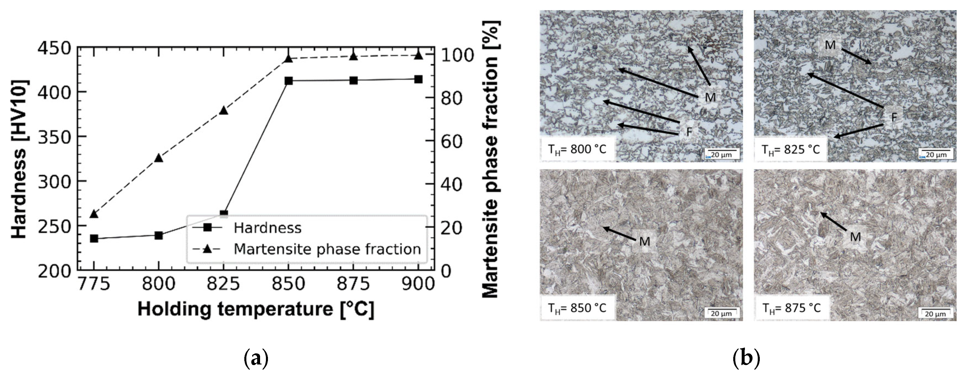
The component simulations showed that an increase in strength at the corners of the crash box leads to an improvement in the overall crash box performance, as seen in Figure 8. In order to fulfill the proposed requirement and achieve similar improvements in the experimental component tests, the local microstructure, and, thus, the mechanical property profile of DP600 steel in the crash box corners, needs to be adapted. The suitable microstructure adjustment can be achieved using a isothermal heat treatment. During this heat treatment, the material is held at a temperature within the austenite-ferrite or fully austenitic range before it is quenched to room temperature. The rapid cooling transforms the austenite into martensite, resulting in a ferritic-martensitic or fully martensitic microstructure whose phase fraction composition, morphology, grain size, and local chemical composition depends on the isothermal heat treatment temperature. The choice of a suitable isothermal holding temperature is, therefore, important to fulfill the requirements from the component simulations. To identify different property profiles, isothermal heat treatments at different temperatures were carried out. In Figure 10b it can be seen that the martensite (M) phase fraction, determined in light optical measurements, increases between 775 °C and 850 °C from 26% to 98%. At the same time, the amount of ferrite (F) in the microstructure decreases proportionally. At higher holding temperatures, the microstructure remains similar and the martensite fraction shows a low variation of 1–2%. A similar trend can be found for the hardness profile. The hardness increases with the rising temperature from 235 HV up to 413 HV where a plateau is reached. The constant hardness and the high martensite content above a holding temperature of 850 °C indicate that the Ac3 temperature has been reached. This hypothesis was verified by dilatometry studies. According to the investigations, the Ac3 temperature lies at 837 °C.
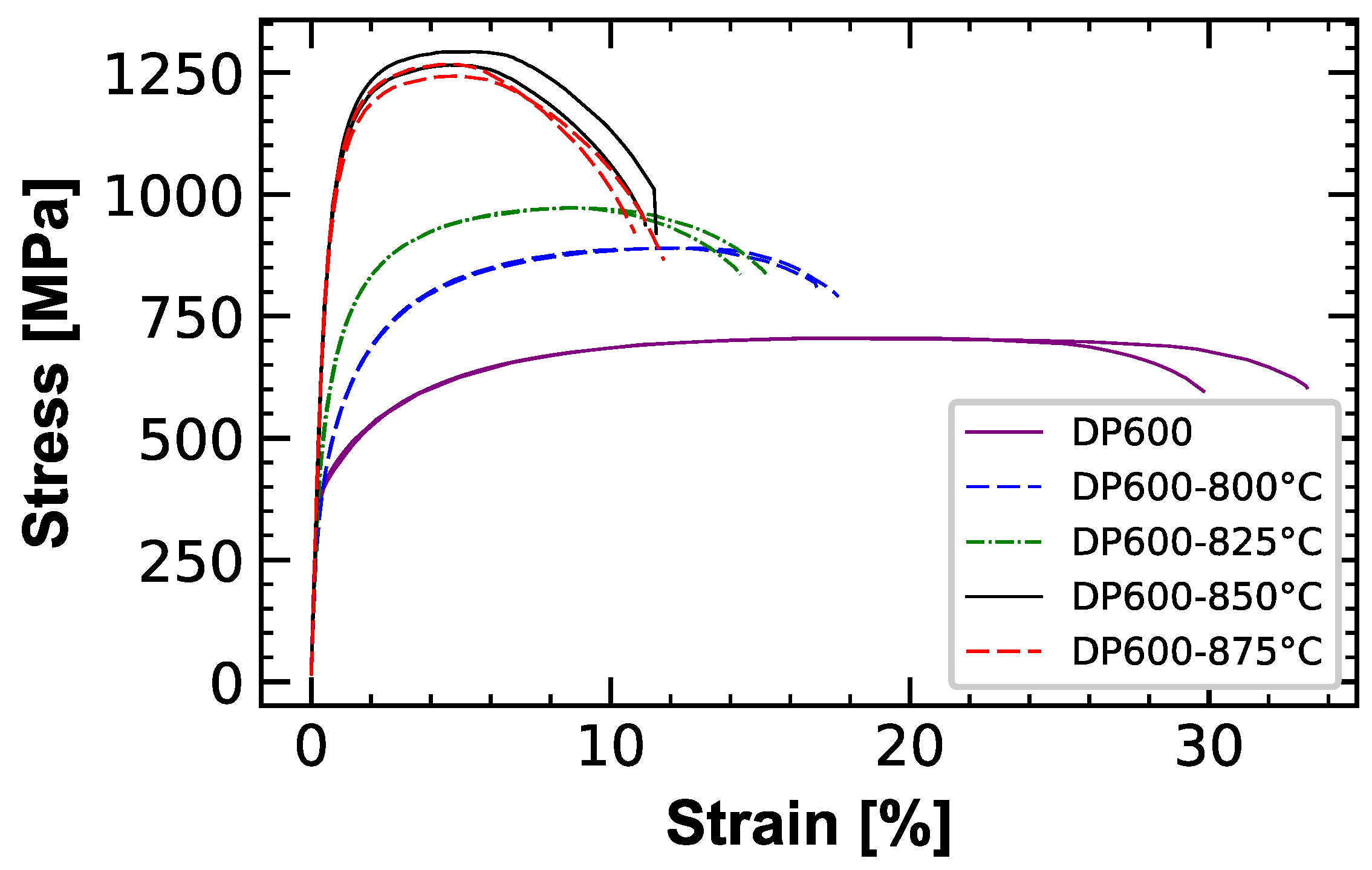
Based on the previous results, tensile test specimens were processed at a holding temperature ranging from 800 °C to 875 °C. Figure 11 shows the stress–strain curves of the heat-treated DP600 specimens. It can be seen that yield strength and ultimate tensile strength increase with higher holding temperatures, while the uniform and total elongation decrease. However, the stress–strain curves at a holding temperature of 850 °C and 875 °C show similar behaviors, which correlates to the microstructural and hardness findings.
From the tensile test curves, it is clear to see that the strength level required by the component simulation, i.e., U1400, cannot be achieved completely, but at least the desired UTS level can be approximated using an isothermal heat treatment at 850–875 °C. Thus, a reasonable process window could be defined for the process-adapted heat treatment:
According to isothermal heat treatment, the local property requirements can best be met by the isothermal heat treatment of DP600 steel for 60 s at a holding temperature of 850 °C.

3.3. Component Assessment of the Local Heat-Treated Crash Boxes Using FEA

Since the isothermal heat treatment in the salt bath was not applicable to the crash box, due to the limitation of the applied process-adapted heat treatments, the component validation was carried out based on FE analysis. For this purpose, extracted material behavior of the heat-treated steel at 850 °C was considered for the crash box corners (see Figure 11) and its flow curve was extrapolated using the Voce function to produce the required material card for the simulation. This material card is named ISO-HT850. It should be considered that the residual stresses resulting from the localized heat treatment of the corners were not modelled and were not taken into consideration. The simulated crash box shows a 58% energy-absorption increase compared to the DP600 crash box (the reference model), which is much more than that of the artificial U1400-strengthened crash box, i.e., 32%, as seen in Table 2. Comparing the energy absorption of the U1400- and ISO-HT850-strengthened crash boxes, even though the ISO-HT850 steel has a lower ultimate stress than the artificial U1400, its energy absorption is higher. The higher energy absorption is related to the higher strain hardening in the early phase of yielding in ISO-HT850. The high energy absorption can be explained by considering that a significant portion of the crash box is deformed plastically at relatively small equivalent-plastic strains, and the ISO-HT850 affects this portion much more than the U1400. However, the strong hardening at the beginning of the ISO-HT850 flow curve results in an unfavorable sharp increase in the peak force as well. In contrast to the high peak force of the ISO-HT850-strengthened crash box, the peak force of U1000-, U1200-, and U1400-strengthened crash boxes are almost the same as the DP600 reference model (Table 2). The sharp increase in the peak force can be explained by analyzing the fold-creation mechanism. In a plastically buckled crash box, by Increasing the stress beyond the yield point, material stiffness, E, decreases significantly, which results in a local buckling and fold creation on the crash box (see Equation (3)). Therefore, the fold is created at relatively small plastic strain values. Thus, both the yield stress and hardening behavior of the material in the low strain region affect the peak force. For a better investigation, a new material card, named U1400Y952, was defined with the same yield stress as ISO-HT850 (952 MPa) and higher ultimate stress i.e., 1400 MPa. Quite a similar hardening behavior of DP600 was used for U1400Y952. Therefore, this material card has a lower hardening behavior than ISO-HT850 at low strain values, as seen in Figure 12a. Comparing the crash boxes strengthened with ISO-HT850 and U1400Y952 material cards, even though both absorb almost the same amount of energy, U1400Y952 has a 5.3% lower peak force due to a lower hardening behavior, as seen in Table 2 and Figure 12b. Figure 12 shows that the yield stress and hardening behavior of the flow curve both affect the peak force; however, the yield stress has a much more considerable effect.
Corner strengthening of crash boxes using materials with a low yield stress, a smooth increase in the hardening and high ultimate stress enhances the crash box energy absorption and reduces the destructive increase in the peak force.
Table 2 sums up FE results of the corner-strengthened crash boxes using different material cards.
Table 2. Extracted parameters of the Voce hardening function for the materials and energy absorption of the related corner-strengthened crash boxes. ISO-HT material cards are related to the heat-treated DP600 steel and were extracted experimentally, see Figure 11.
MaterialK0 (MPa)Q (MPa)b (-)UTS (MPa)Fpeak (kN)Energy Absorption (kJ)Normalized Energy-Absorption Change (%)
DP600388.7447.417.9841956.13-
U1000388.762119.11000956.475.5
U1200388.7829.320.3120097.57.2317.9
U1400388.7102320.6140098.58.0831.8
ISO-HT800°398.3569.647.2992101.37.2918.9
ISO-HT825°516.3515.870.81059110.357.9329.4
ISO-HT850°952387.1146.113591379.3652.7
ISO-HT875°920.8386.1156.21326137.19.6657.6
U1400Y952952453.9201400129.49.4253.67

3.4. Benefits of Corner-Strengthening on Crash Box Progressive-Buckling Behavior

Enhancing the energy absorption capacity of a crash box should not endanger its progressive buckling. Using Equation (3) elastic buckling stress of the experimentally tested crash box can be calculated as 1888 MPa. The calculated buckling stress is higher than the yield stress of the DP600 steel, i.e., 389 MPa, and it is expected that the crash box buckles progressively, which is confirmed by the experimental results (Figure 6). In order to explore the advantages of corner-strengthening the crash box over homogenous heat treatment of it, three simulations were conducted using the validated FE model. By decreasing the crash box thickness to 1 mm, the critical buckling stress of the crash box decreases to 451 MPa. The buckling stress is below the yield stress of the ISO-HT850 steel, i.e., 952 MPa. However, the buckling stress is still beyond the yield stress of the DP600 steel. Two simulations were conducted on crash boxes using the DP600 steel and ISO-HT850 material cards. An FE model of the crash box with an ISO-HT850 material card simulates the behavior of a globally heat-treated DP600 crash box. The results are shown in Figure 13a,c. As was predicted, the globally heat-treated crash box buckles unprogressively, but the crash box made by DP600 steel buckles progressively. For longer crash boxes, this unprogressive behavior can result in global bending of the crash box, which prevents the energy absorption process. A corner-strengthened crash box was simulated in addition to the previous simulations. Material properties of the DP600 steel were used for the midplate region and ISO-HT850 material card was applied to the corners (see Figure 12a). The corner-strengthened crash box shows progressive behavior and produces the same number of the folds as DP 600 crash box, as seen in Figure 13b. Thus, by not strengthening the global crash box and only strengthening its corners, the energy absorption can be increased without any critical change in the crushing behavior.
The conducted FE simulations revealed the potential of the component-driven material design approach in improving the crash box performance by retaining its progressive buckling. FE simulations reveal a 52% increase in the energy absorption of the crash box, which is due to the improved balance of ductility and strength of the material at the crash box corners. However, more sophisticated material models are required to extract the exact value of this balance in order to prevent large cracks at the corners. The capacity of the strength increase in DP600 steel was explored by conducting experimental heat treatments (see Figure 11). However, for a precise selection of the heat treatment temperature further tests are required to analyze the ductility changes as well, as a very low ductility can result in large cracks in the crash box. As was mentioned, even though small cracks do not affect the crash box performance [10,45], the production of large cracks shall be prevented. Therefore, the ductility of the heat-treated steel should be considered for selecting a proper heat treatment.

3.5. Evaluation of Component-Driven Material Design Approach in the Context of Other Methodologies

An increase in component performance can be achieved through either a material, process, or design modification [23,26,34]. In most cases, material-related approaches first obtain improved mechanical material properties by means of heat treatment strategies, which then positively influence the component behavior [34]. However, as there is a strong interaction of material properties and geometric size in terms of the buckling behavior of the crash box, this straight material-driven approach may result in a less optimal design than was demonstrated by the presented crash box configuration. In fact, the integration of this interaction is crucial for a real lightweight design process. The introduced approach of the component-driven material design reveals a possible way to realize it. In addition to the mechanical properties addressed in this paper, this approach also makes it possible on the one hand to extend the range of properties and requirements to include, for example, corrosive, welding, and functional properties and on the other hand to fully exploit local property profiles. The authors see further potential to increase the integrated component performance through a numerical consideration of the process control and the associated microstructure evolution. Both the potential transferability of the methodology to other scientific and technical challenges and the flexibility of the approach offer further potential for the presented approach.

3.6. Adaptive Corner Heat Treatment to Improve Crash Box Energy Absorption

To achieve the investigated effect of corner-reinforced crash boxes, different heat treatment methods can be applied. Since the local heat treatment of the corners of a crash box cannot be carried out by heat treatments using salt baths, other heat treatment methods have to be taken into account. One possibility is the use of a moving heat source, e.g., welding devices. In the following, several options are discussed to locally adapt the heat treatment in a process chain. To provide a flexible process, which could be used for several applications and heat treatments, the local heat treatment method must have a large working range and a high energy density to achieve the required spatial resolution. Traditionally, an oxy-acetylene torch has been used for such tasks. The flame straightening method, for example, uses local heat input to reduce deformations in components. However, with this method, spatial resolution is limited by the heat distribution properties within the oxyfuel flame. Since arc welding processes have a higher energy density than oxyfuel processes, it is obvious to use an adapted and power-reduced tungsten inert gas (TIG) welding torch for the above purpose. Comparable to the TIG process with even higher energy density, a plasma welding torch can also be used. In these arc welding processes, the power is reduced until surface melting no longer occurs. Since the equipment is readily available and relatively affordable, preliminary tests have already been carried out. As the results have not yet been verified, only initial observations can be presented here, although some challenges have arisen for further investigation of local heat treatment. On the one hand, the time window in which the heat input is not sufficient to melt the surface of the component is quite small, and on the other hand, the geometry of the component and, thus, the possibilities of heat dissipation strongly influence the effect of the heat treatment. The resulting microstructure is comparable to the heat-affected zone (HAZ) in welding processes, a gradient of coarse-grain and fine-grain zones. The effective properties of these gradient zones need to be considered in future simulation studies. Finally, selective heat treatment by laser or electron beams is also conceivable. Similar to the results of [33], the use of a high energy density beam allows for very good spatial resolution, and at least in the case of the electron beam, it is possible to influence the beam path with a very high frequency. The disadvantage of this type of treatment is the very high acquisition costs of such a system and the associated limited applicability in the process chain.

4. Conclusions and Outlook

In this paper, the component-driven material design approach was introduced as a design process to get an optimal material design for a given geometric configuration of crash boxes. First, by analyzing the crushing behavior of square crash boxes, the requirements to retain their progressive buckling were analyzed. It was shown that the increase in the yield stress should be restricted to the corner regions of the crash box in order to retain its progressive buckling behavior. Starting from a calibrated and validated FE model of the crash box with its given dimensions a corridor of optimal material properties could be specified. Subsequently, isothermal heat treatment strategies and material characterization methods, including light-optical microstructure, hardness, and tensile property measurements, were used to achieve the required property profile.
The potential of the inverted process chain is assessed using finite element analysis and the material card extracted by the isothermal heat treatment. This analysis shows a considerably high increase in the energy absorption of the crash boxes.
The effect of the corner-strengthening on crash box features was studied by conducting parametric studies on the material properties of the corners. The results show that high ultimate stress besides a low yield point and low hardening behavior at the beginning of the flow curve not only enhances the crash box energy absorption but also reduces the destructive increase in the peak force. Among the mentioned material properties, the yield stress effect on the peak force is considerably higher than the others.
In the future, the introduced design approach will be coupled with local strain requirements derived from simulations and experiments. Additionally, the local heat treatment of the crash boxes will be carried out by applying the heat treatment strategies discussed in Section 3.6 in order to extend the component-driven material design approach by using a customized process design.

Author Contributions

Conceptualization, N.J.-A., Y.S., J.Z., K.A.G.M., R.S., S.M. and K.-U.S.; methodology, N.J.-A., K.-U.S. and S.M.; software, N.J.-A.; validation, N.J.-A., Y.S., J.Z. and K.A.G.M.; formal analysis N.J.-A., Y.S., J.Z. and K.A.G.M.; investigation, N.J.-A., Y.S., J.Z. and K.A.G.M.; resources, K.-U.S. and S.M.; data curation, N.J.-A., Y.S., J.Z. and K.A.G.M.; writing—original draft preparation, N.J.-A., Y.S., J.Z. and K.A.G.M.; writing—review and editing, N.J.-A.; visualization, K.A.G.M. and N.J.-A.; supervision, R.S., K.-U.S. and S.M.; project administration, K.-U.S. and S.M.; funding acquisition, K.-U.S. and S.M. All authors have read and agreed to the published version of the manuscript.

Funding

This research received no external funding.

Institutional Review Board Statement

Not applicable.

Informed Consent Statement

Not applicable.

Data Availability Statement

The raw/processed data required to reproduce these findings cannot be shared at this time due to time limitations.

Conflicts of Interest

The authors declare no conflict of interest.

References

  1. Abramowicz, W.; Jones, N. Dynamic axial crushing of circular tubes. Int. J. Impact Eng. 1984, 2, 263–281. [Google Scholar] [CrossRef]
  2. Abramowicz, W.; Jones, N. Dynamic axial crushing of square tubes. Int. J. Impact Eng. 1984, 2, 179–208. [Google Scholar] [CrossRef]
  3. Wierzbicki, T.; Abramowicz, W. On the Crushing Mechanics of Thin-Walled Structures. J. Appl. Mech. 1983, 50, 727–734. [Google Scholar] [CrossRef]
  4. Abramowicz, W.; Jones, N. Transition from initial global bending to progressive buckling of tubes loaded statically and dynamically. Int. J. Impact Eng. 1997, 19, 415–437. [Google Scholar] [CrossRef]
  5. Abramowicz, W.; Jones, N. Dynamic progressive buckling of circular and square tubes. Int. J. Impact Eng. 1986, 4, 243–270. [Google Scholar] [CrossRef]
  6. Mahmood, H.F.; Paluszny, A. Design of Thin Walled Columns for Crash Energy Management—Their Strength and Mode of Collapse; SAE Technical Paper (811302); SAE International: Warrendale, PA, USA, 1981. [Google Scholar]
  7. Karagiozova, D.; Alves, M. Transition from progressive buckling to global bending of circular shells under axial impact––Part I: Experimental and numerical observations. Int. J. Solids Struct. 2004, 41, 1565–1580. [Google Scholar] [CrossRef]
  8. Müller, B.; Schagerl, M.; Schröder, K.-U. Prediction of the collapse mode of axially crushed profiles. Proc. Inst. Civ. Eng.—Struct. Build. 2013, 166, 456–464. [Google Scholar] [CrossRef]
  9. Zhang, X.; Su, H.; Yu, T. Energy absorption of an axially crushed square tube with a buckling initiator. Int. J. Impact Eng. 2009, 36, 402–417. [Google Scholar] [CrossRef]
  10. Liu, W.; Lian, J.; Münstermann, S.; Zeng, C.; Fang, X. Prediction of crack formation in the progressive folding of square tubes during dynamic axial crushing. Int. J. Mech. Sci. 2020, 176, 105534. [Google Scholar] [CrossRef]
  11. Singer, J.; Arbocz, J.; Weller, T. Buckling Experiments: Experimental Methods in Buckling of Thin-Walled Structures; Volume 2: Shells, Built-up Structures, Composites and Additional Topics; John Wiley & Sons: Hoboken, NJ, USA, 2002. [Google Scholar]
  12. Jones, N. Structural Impact; Cambridge University Press: Cambridge, UK, 1990. [Google Scholar]
  13. Baroutaji, A.; Sajjia, M.; Olabi, A.-G. On the crashworthiness performance of thin-walled energy absorbers: Recent advances and future developments. Thin-Walled Struct. 2017, 118, 137–163. [Google Scholar] [CrossRef]
  14. Karagiozova, D.; Marcílio, A. Dynamic elastic-plastic buckling of structural elements: A review. Appl. Mech. Rev. 2008, 61, 40803. [Google Scholar] [CrossRef]
  15. Singer, J.; Arbocz, J.; Weller, T. Buckling Experiments. Experimental Methods in Buckling of Thin-walled Structure. Volume 1: Basic Concepts, Columns, Beams, and Plates; John Wiley & Sons Inc.: New York, NY, USA, 1998. [Google Scholar]
  16. Hanssen, A.; Langseth, M.; Hopperstad, O. Static and dynamic crushing of square aluminium extrusions with aluminium foam filler. Int. J. Impact Eng. 2000, 24, 347–383. [Google Scholar] [CrossRef]
  17. Meguid, S.; Stranart, J.; Heyerman, J. On the layered micromechanical three-dimensional finite element modelling of foam-filled columns. Finite Elem. Anal. Des. 2004, 40, 1035–1057. [Google Scholar] [CrossRef]
  18. Jones, N. Energy-absorbing effectiveness factor. Int. J. Impact Eng. 2010, 37, 754–765. [Google Scholar] [CrossRef]
  19. Rezvani, M.J.; Jahan, A. Effect of initiator, design, and material on crashworthiness performance of thin-walled cylindrical tubes: A primary multi-criteria analysis in lightweight design. Thin-Walled Struct. 2015, 96, 169–182. [Google Scholar] [CrossRef]
  20. Wang, C.; Li, Y.; Zhao, W.; Zou, S.; Zhou, G.; Wang, Y. Structure design and multi-objective optimization of a novel crash box based on biomimetic structure. Int. J. Mech. Sci. 2018, 138–139, 489–501. [Google Scholar] [CrossRef]
  21. Jones, N.; Birch, R.S. Dynamic and Static Axial Crushing of Axially Stiffened Square Tubes. Proc. Inst. Mech. Eng. Part C Mech. Eng. Sci. 1990, 204, 293–310. [Google Scholar] [CrossRef]
  22. Yao, R.-Y.; Yin, G.-S.; Hao, W.-Q.; Zhao, Z.-Y.; Li, X.; Qin, X.-L. Axial buckling modes and crashworthiness of circular tube with external linear gradient grooves. Thin-Walled Struct. 2019, 134, 395–406. [Google Scholar] [CrossRef]
  23. Nikkhah, H.; Baroutaji, A.; Olabi, A.G. Crashworthiness design and optimisation of windowed tubes under axial impact loading. Thin-Walled Struct. 2019, 142, 132–148. [Google Scholar] [CrossRef]
  24. Shuo, L. Impact Energy Absorption Analysis of Different Thin-Walled Tubes with and without Reinforcement. Ph.D. Thesis, University of Manchester, Manchester, UK, 2014. [Google Scholar]
  25. Huang, H.; Xu, S. Crashworthiness analysis and bionic design of multi-cell tubes under axial and oblique impact loads. Thin-Walled Struct. 2019, 144, 106333. [Google Scholar] [CrossRef]
  26. Fang, J.; Gao, Y.; Sun, G.; Zheng, G.; Li, Q. Dynamic crashing behavior of new extrudable multi-cell tubes with a functionally graded thickness. Int. J. Mech. Sci. 2015, 103, 63–73. [Google Scholar] [CrossRef]
  27. Li, Z.; Ma, W.; Hou, L.; Xu, P.; Yao, S. Crashworthiness analysis of corrugations reinforced multi-cell square tubes. Thin-Walled Struct. 2020, 150, 106708. [Google Scholar] [CrossRef]
  28. Zhang, X.; Wen, Z.; Zhang, H. Axial crushing and optimal design of square tubes with graded thickness. Thin-Walled Struct. 2014, 84, 263–274. [Google Scholar] [CrossRef]
  29. Xu, F.; Tian, X.; Li, G. Experimental Study on Crashworthiness of Functionally Graded Thickness Thin-Walled Tubular Structures. Exp. Mech. 2015, 55, 1339–1352. [Google Scholar] [CrossRef]
  30. Yang, R.J.; Fu, Y.; Li, G. Application of Tailor Rolled Blank in Vehicle Front End for Frontal Impact. In SAE Technical Paper Series; SAE International: Warrendale, PA, USA, 2007. [Google Scholar]
  31. Xu, F.; Sun, G.; Li, G.; Li, Q. Experimental study on crashworthiness of tailor-welded blank (TWB) thin-walled high-strength steel (HSS) tubular structures. Thin-Walled Struct. 2014, 74, 12–27. [Google Scholar] [CrossRef]
  32. Demirci, E.; Yildiz, A.R. An experimental and numerical investigation of the effects of geometry and spot welds on the crashworthiness of vehicle thin-walled structures. Mater. Test. 2018, 60, 553–561. [Google Scholar] [CrossRef]
  33. Bambach, M.; Conrads, L.; Daamen, M.; Güvenç, O.; Hirt, G. Enhancing the crashworthiness of high-manganese steel by strain-hardening engineering, and tailored folding by local heat-treatment. Mater. Des. 2016, 110, 157–168. [Google Scholar] [CrossRef]
  34. Quadfasel, A.; Teller, M.; Madivala, M.; Haase, C.; Roters, F.; Hirt, G. Computer-Aided Material Design for Crash Boxes Made of High Manganese Steels. Metals 2019, 9, 772. [Google Scholar] [CrossRef]
  35. Conrads, L.; Liebsch, C.; Hirt, G. Increasing the energy absorption capacity of structural components made of low alloy steel by combining strain hardening and local heat treatment. Procedia Eng. 2017, 207, 257–262. [Google Scholar] [CrossRef]
  36. Hosseini, V.A.; Karlsson, L.; Hurtig, K.; Choquet, I.; Engelberg, D.; Roy, M.J.; Kumara, C. A novel arc heat treatment technique for producing graded microstructures through controlled temperature gradients. Mater. Des. 2017, 121, 11–23. [Google Scholar] [CrossRef]
  37. European Aluminium Association. The Aluminuym Automotive Manual—Design for Functional Performance; European Aluminium Association: Etterbeek, Belgium, 2011. [Google Scholar]
  38. Ituarte, I.F.; Boddeti, N.; Hassani, V.; Dunn, M.L.; Rosen, D.W. Design and additive manufacture of functionally graded structures based on digital materials. Addit. Manuf. 2019, 30, 100839. [Google Scholar] [CrossRef]
  39. Boddeti, N.; Tang, Y.; Maute, K.; Rosen, D.W.; Dunn, M.L. Optimal design and manufacture of variable stiffness laminated continuous fiber reinforced composites. Sci. Rep. 2020, 10, 16507. [Google Scholar] [CrossRef] [PubMed]
  40. Gebhardt, C.; Nellessen, J.; Bührig-Polaczek, A.; Broeckmann, C. Influence of Aluminum on Fatigue Strength of Solution-Strengthened Nodular Cast Iron. Metals 2021, 11, 311. [Google Scholar] [CrossRef]
  41. Ripplinger, C.; Gastens, M.; Zimmermann, J.; Pustal, B.; Broeckmann, C.; Schröder, K.-U.; Bührig-Polaczek, A. Potential of Metallurgical Gradients in the Design of Structural Components Made of Nodular Cast Iron. Materials 2021, 14, 2411. [Google Scholar] [CrossRef] [PubMed]
  42. Müller, B. Druckfestigkeit und Stauchverhalten Dünnwandiger Profile. Ph.D. Thesis, Johannes Kepler Universität Linz, Linz, Austria, 2013. [Google Scholar]
  43. Müller, B.; Schagerl, M.; Schöder, K.-U. On the folding of plates which buckle before and beyond the elastic limit. PAMM 2013, 13, 111–112. [Google Scholar] [CrossRef]
  44. Chen, D. Crush Mechanics of Thin-Walled Tubes; CRC Press: Boca Raton, FL, USA, 2015. [Google Scholar]
  45. Jafarzadeh-Aghdam, N.; Schröder, K.-U. Mechanism of reproducible axial impact of square crash boxes. Thin-Walled Struct. 2022, 176, 109062. [Google Scholar] [CrossRef]
  46. Meguid, S.; Attia, M.; Stranart, J.; Wang, W. Solution stability in the dynamic collapse of square aluminium columns. Int. J. Impact Eng. 2007, 34, 348–359. [Google Scholar] [CrossRef]
  47. Jafarzadeh-Aghdam, N.; Tatikonda, U.B.C.; Bühring, J.; Mekala, N.R.; Schröder, K.-U. Impact of thin-walled square aluminum tubes. Proc. Appl. Math. Mech. 2019, 19, e201900395. [Google Scholar] [CrossRef]
  48. Jafarzadeh-Aghdam, N. Crush Mechanics of Square Tubes. Ph.D. Dissertation, RWTH Aachen University, Aachen, Germany, 2022. [Google Scholar]
  49. Chung, K.; Lee, M.-G. Basics of Continuum Plasticity; Springer: Singapore, 2018. [Google Scholar] [CrossRef]
  50. Costas, M.; Díaz, J.; Romera, L.; Hernández, S.; Tielas, A. Static and dynamic axial crushing analysis of car frontal impact hybrid absorbers. Int. J. Impact Eng. 2013, 62, 166–181. [Google Scholar] [CrossRef]
  51. Dassault Systems, Abaqus. Online Documentation-Abaqus Analysis User’s Guide. 2017. Available online: http://130.149.89.49:2080/v6.11/pdf_books/CAE.pdf (accessed on 26 March 2023).
  52. Langseth, M.; Hopperstad, O.; Berstad, T. Crashworthiness of aluminium extrusions: Validation of numerical simulation, effect of mass ratio and impact velocity. Int. J. Impact Eng. 1999, 22, 829–854. [Google Scholar] [CrossRef]
  53. Haberle, T. Buckling of flat, rectangular plates under uniaxial compression: Handbuch struktur berechnung (HSB). In Handbuch Struktur Berechnung; Industrie-Ausschufl Struktur Berechnungsunterlagen: Ottobrunn, Germany, 2009; p. 2. [Google Scholar]
  54. Timoshenko, S.; Gere, J. Theory of Elastic Stability, 2nd ed.; McGraw-Hill: New York, NY, USA, 1963. [Google Scholar]
  55. Langseth, M.; Hopperstad, O. Local buckling of square thin-walled Aluminium extrusions. Thin-Walled Struct. 1997, 27, 117–126. [Google Scholar] [CrossRef]
  56. Schuman, L.; Goldie, B. Strength of rectangular flat plates under edge compression. NACA-TR-356. NACA Tech. Rep. 1931, 356. [Google Scholar]
  57. Jafarzadeh-Aghdam, N.; Schröder, K.-U. Dynamic buckling of crash boxes Under impact load. In Proceedings of the 8th International Conference on Coupled Instabilities in Metal Structures (CIMS 2021), Lodz, Poland, 12–14 July 2021. [Google Scholar] [CrossRef]
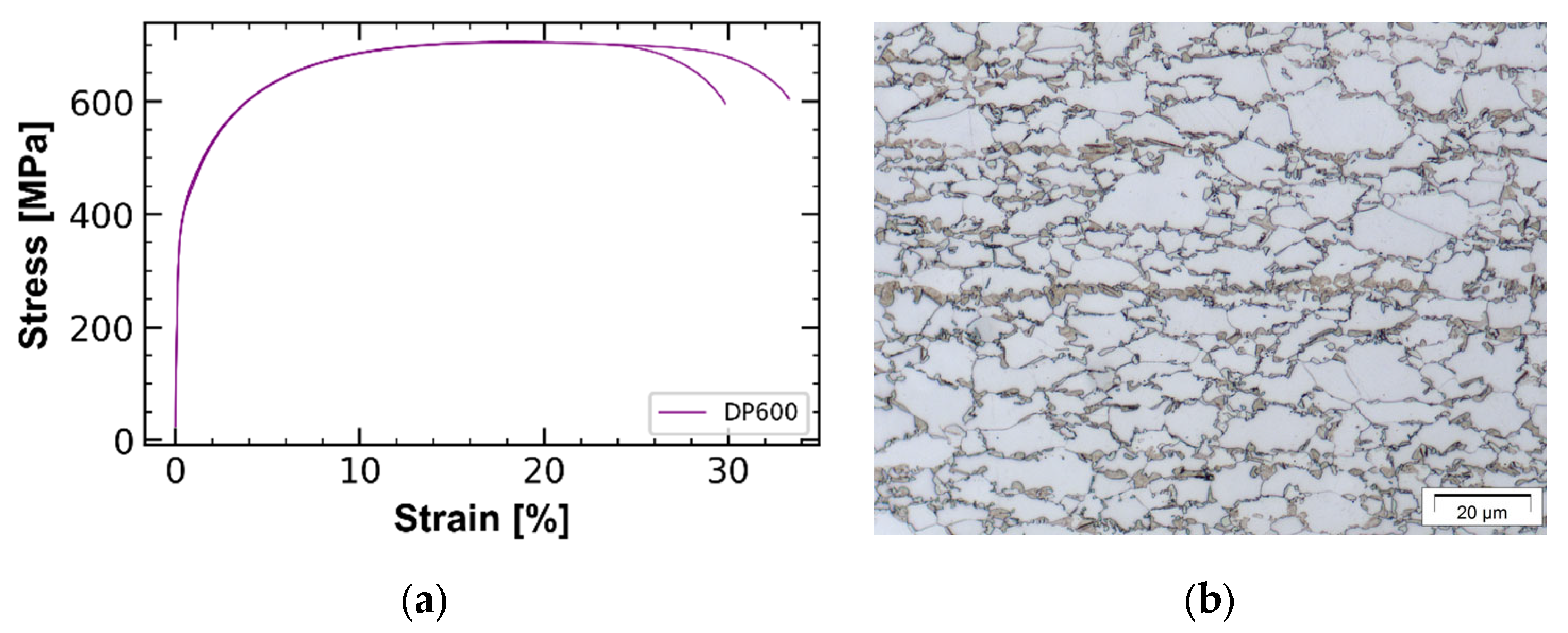
Figure 1. (a) Stress–strain curve (two tests were conducted); (b) Microstructure of DP600.
Metals 13 00915 g001
Figure 2. Schematic process map of the component-driven material design approach.
Metals 13 00915 g002
Figure 3. The experimental setup for quasistatic compression of the crash box. DIC method was used to investigate the local strains. Dimensions of the crash box are shown in Figure 4a.
Metals 13 00915 g003
Figure 4. (a) Dimensions of the tested crash boxes; the thickness of the crash boxes is 1.5 mm. (b) Imperfection on the simulated crash box at the second-fold region (exaggerated). (c) Force–displacement diagrams of the experimental test and numerical simulation of DP600 crash box (none heat-treated).
Metals 13 00915 g004
Figure 5. Comparison of the out-of-plane displacement in the x-direction (U1) for peak force between FE analysis (left) and experiment (right) captured using the DIC method. The unit of the displacement is mm.
Metals 13 00915 g005
Figure 6. (a) Validated FE mode; (b) Experimental test result of the crash box with DP600 steel material behavior.
Metals 13 00915 g006
Figure 7. Crash box under compression load F with the plate regions engaged in a local fold. By increasing the load the midregion of the plate (marked by 2) buckles first and the load transfers to its side areas (marked by 1).
Metals 13 00915 g007
Figure 8. (a) Extrapolated DP600 steel and the artificial flow curves defined for corner-strengthening of the crash box; (b) FE results of DP600 crash box and U1400-strengthened crash box. Force–displacement diagrams of U1000 and U1200-strengthened crash boxes are located between the shown graphs; (c) Absolute and proportional (compared to DP600) energy absorption for each artificial material.
Metals 13 00915 g008aMetals 13 00915 g008b
Figure 9. Requirement definition of the corner-strengthened crash box (depicted as a radar chart) and corresponding microstructures (schematic). Blue and yellow marked regions are named mid and side regions of the crash box accordingly.
Metals 13 00915 g009
Figure 10. (a) Influence of the isothermal holding temperature on the hardness and martensite phase fraction of heat-treated DP600; (b) Light optical microscopy images of the heat-treated DP600, Nital etching. M and F stands for martensite and ferrite respectively.
Metals 13 00915 g010
Figure 11. Stress–strain curves of heat-treated DP600 samples.
Metals 13 00915 g011
Figure 12. (a) Material cards used for FE simulation; (b) FE results of DP600, ISO-HT850-strengthened, and U1400Y952-strengthened crash boxes.
Metals 13 00915 g012
Figure 13. Comparing the local heat-treatment and global heat-treatment effects on the crushing behavior of the crash box: (a) The crash box made of DP600 steel; (b) Corner-strengthened crash box; (c) Globally heat-treated crash box. The globally heat-treated crash box does not show progressive bucking and after a few local folds the stable crushing behavior is stopped.
Metals 13 00915 g013
Table 1. Chemical composition of DP600 steel, in mass %.
CSiMnPCuCrMoNiN
0.1130.3901.380.01670.01520.1790.05150.01980.00001
Disclaimer/Publisher’s Note: The statements, opinions and data contained in all publications are solely those of the individual author(s) and contributor(s) and not of MDPI and/or the editor(s). MDPI and/or the editor(s) disclaim responsibility for any injury to people or property resulting from any ideas, methods, instructions or products referred to in the content.