Article

Multi-Physical Field Coupling Simulation and Experiments with Pulse Electrochemical Machining of Large Size TiAl Intermetallic Blade

College of Mechanical and Electrical Engineering, Nanjing University of Aeronautics and Astronautics, 29 Yudao Street, Nanjing 210016, China
*
Author to whom correspondence should be addressed.
Metals 2023, 13(5), 985; https://doi.org/10.3390/met13050985
Submission received: 26 April 2023 / Revised: 15 May 2023 / Accepted: 16 May 2023 / Published: 19 May 2023

Abstract

:
Large size TiAl alloy blade is one of the important parts to reduce the weight of advanced aero-engines. However, the precision manufacturing of such blades is a challenge due to their large size, low ductility at room temperature, and high hardness of the TiAl alloy. Electrochemical machining (ECM) is a very promising method for the precision manufacturing of such blades, considering its unique advantages. In this study, a very comprehensive multi-physical field coupling simulation and pulse ECM experiments on large size TiAl alloy blades are carried out. Geometric and theoretical models involving electric fields, gas-liquid two-phase flow, heat transfer, and anodic dissolution are developed. The variation of bubble, temperature, electrolyte flow rate, and electrical conductivity at the outlet and the different areas on the blade surface with the processing time and distribution along the flow channel in the machining gap are revealed by simulation. It is found that the influence of electrolyte temperature on electrical conductivity is more dominant than that of bubble concentration. Finally, the experiments of pulse ECM on large size TiAl alloy blade are carried out, and the experimental results are analyzed in detail. The high efficiency and high surface quality of large size TiAl alloy blades are realized. The surface roughness and machining accuracy of the blade are about Ra 0.9 μm and 0.18 mm, respectively.

1. Introduction

With the rapid development of advanced aerospace technology, the performance of aero-engines has become more demanding. In order to further reduce the weight of the aero-engine, improvement of its thrust-to-weight ratio and performance is necessary. One direct and efficient way is to replace the heavier materials in aero-engines with lighter materials. In recent years, TiAl alloy has received a lot of attention and rapid development due to its outstanding advantages, such as its low density (only half that of nickel-base superalloy), high strength, and good corrosion resistance [1]. At present, TiAl alloy has become a typical high-temperature material in aero-engines. Large size TiAl alloy blades have also become an important component of aero-engines. As early as 2006, large size TiAl alloy blades have been successfully applied to aero-engines, which reduce weight and greatly improve the performance of aero-engines [2]. However, although this kind of blade has been successfully applied in aero-engines, it is mainly manufactured by mechanical cutting processes or precision casting, and there are still some problems, such as low machining accuracy and yield, a long processing cycle, and a high manufacturing cost. This is mainly due to the low room temperature ductility and high strength of TiAl alloys, as well as the very large size of such blades (about 30 cm). Therefore, it is necessary to carry out precise, efficient, and low-cost processing technology research for such large size TiAl alloy blades.
Electrochemical machining (ECM) is a typical non-traditional machining technology that is based on the electrochemical anodic dissolution principle to remove materials and involves electric field and flow field theories. ECM has many inherent advantages, such as independent physical properties of metal materials, no tool wear, no recasting layer or cutting force, good surface quality, and high processing efficiency [3,4,5,6,7]. After many years of development, ECM has become the mainstream manufacturing technology for complex structural components of difficult-to-process materials in aero-engines. It is also a low-cost and preferred precision machining technology for large size TiAl alloy blades.
Based on the advantages of ECM in the manufacture of TiAl alloy, many scholars have carried out research on ECM in TiAl alloy. Clifton et al. [8] studied the ECM characteristics and surface integrity of Ti-45Al-2Mn-2Nb (at.%) + 0.8 vol.% TiB2 alloy in perchlorate and chloride solutions. It is found that there are obvious differences in processing characteristics between the two solutions. Liu et al. [9] carried out ECM parameter optimization experiments on Ti-46Al-4Nb-2(Cr,Ta) alloy and discussed the influence of some major machining parameters on the workpiece surface roughness and material removal rate. The surface roughness of the sample reaches Ra 1 μm under the optimal machining parameters. Baehre et al. [10] reported the electrochemical dissolution behavior of pure Ti, Ti90Al6V4, and intermetallic Ti60Al40 in different solutions. The results show that the increase in Ti content will hinder the dissolution of the material. Klocke et al. [11] compared the electrochemical machinability of additive manufacturing and casting TNB-V5 alloy in NaNO3 and NaCl solutions. Wang et al. [12,13,14] investigated the electrochemical dissolution behavior of a variety of TiAl alloys. It was found that the sample in sodium nitrate solution had a better surface quality than that in sodium chloride solution. At present, the reports on ECM of TiAl alloy are mainly focused on basic research, such as electrochemical dissolution behavior, surface integrity, and parameter optimization experiments. However, there are few reports on the ECM of large size TiAl alloy blades.
ECM is a very complex process that combines electric field, flow field, and electrochemical anodic dissolution. In ECM, the distribution of hydrogen, Joule heat, and anode products in the machining gap along the flow channel is not uniform, which will cause the electrolyte conductivity and machining gap along the flow channel distribution to not be uniform. As a result, the machining accuracy of the workpiece becomes worse. Mastering the distribution law of electrolytic products in the machining gap is beneficial to improving the surface quality of the workpiece and the accurate design of the tool electrode profile. Multi-physical field coupling simulation is a very powerful and effective method to reveal the distribution laws of electrolytic products in machining gaps. Klocke et al. [15,16] developed an interdisciplinary model for the ECM of blades and carried out a multi-physical field coupling simulation analysis. The simulation results are in good agreement with the experimental results. Wang et al. [17] proposed a new tangential feeding ECM method for blade leading/trailing edges and studied the distribution of bubbles, temperature, and conductivity at the leading/trailing edges through multi-physical field coupling simulation. Schaarschmidt et al. [18] studied the characteristics of precision ECM with pulse and vibration coupling through multi-physical field coupling simulation. Chen et al. [19] predicted the ECM gap using a multi-physical field coupling simulation based on two-phase turbulence flow. Wang et al. [20] studied the formation process of rhomboid holes in pulse and vibration coupling ECMs based on multi-physical field coupling simulation. For the large size TiAl alloy blade, the distribution of electrolytic products in the machining gap is not known, which is not conducive to the accurate design of the tool electrode profile and blade forming process analysis.
Therefore, the multi-physical field coupling simulation and experiments of large size TiAl blade are studied in this study. The purpose is to reveal the distribution laws of electrolytic products in the machining gap and obtain blades with high surface quality and high machining accuracy. Firstly, the machining principle of large size TiAl alloy blade by pulse ECM is described. Then, a two-dimensional geometry model and a theoretical model of multi-physical field coupling simulation are established. Furthermore, the simulation results of multi-physical field coupling for pulse ECM of large size TiAl alloy blade are analyzed in detail. The variation of bubble volume fraction, temperature, electrolyte flow rate, and electrical conductivity at the outlet and the different areas on the blade surface with the processing time and distribution law along the flow channel in the machining gap at the pulse-on time are revealed. Finally, the ECM experiments with large size TiAl alloy blade are carried out on the self-developed equipment system. The surface roughness of the machined blade is about Ra 0.9 μm, and the machining accuracy is about 0.18 mm. In addition, it is worth mentioning that although the object of study in this paper is large size TiAl alloy blade, the research method and mathematical model are also suitable for similar blades, blisks, or diffuser parts of other materials, which has good universality.

2. Principles of ECM for Large Blades

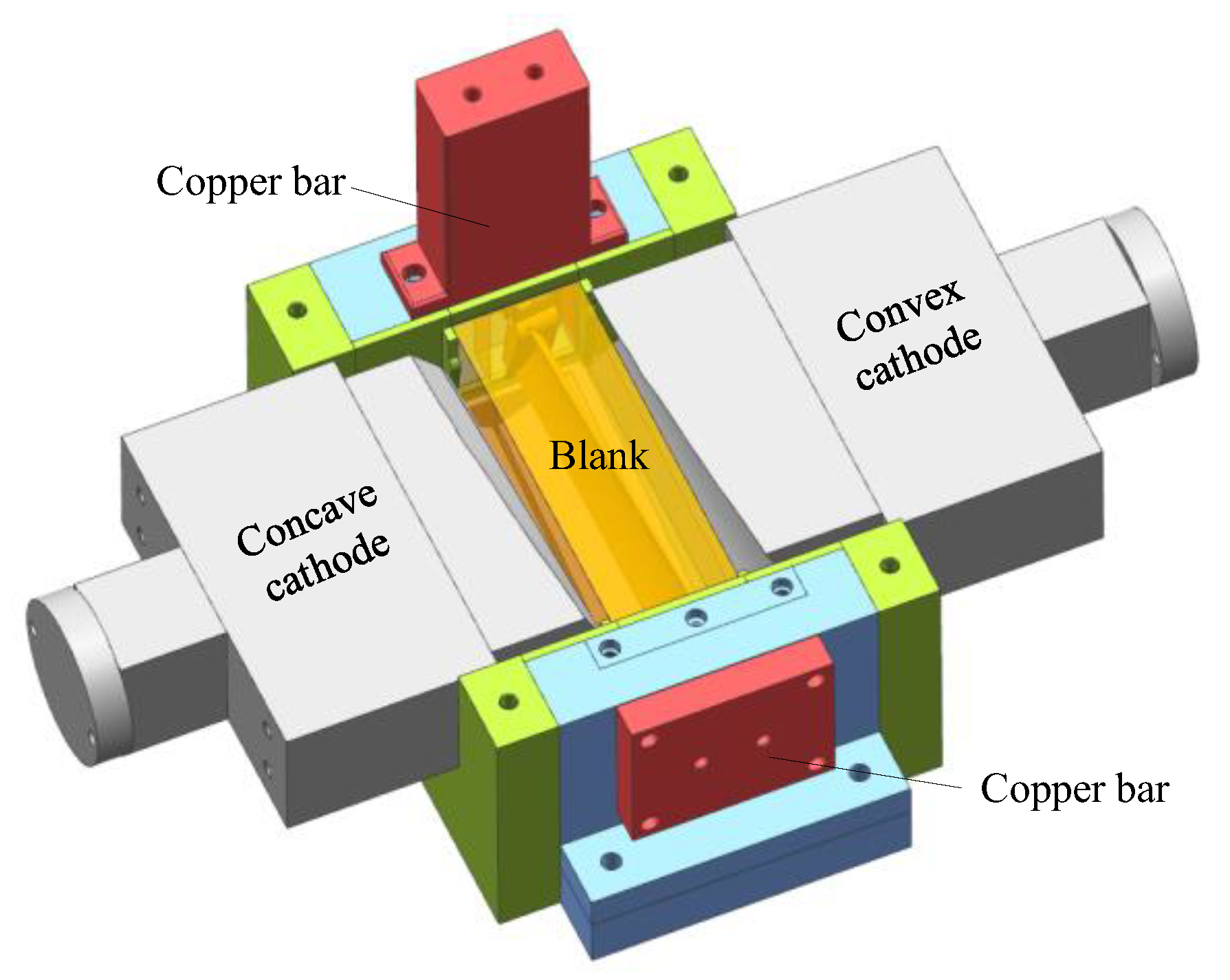
ECM is a typical non-contact machining method. Figure 1 shows the principle of ECM for large size TiAl alloy blade. At the beginning of ECM, the convex and concave tools with complex profiles are used as the cathode to connect with the negative pole of a high-power pulse power supply, and the large size TiAl alloy blade is used as the anode to connect with the positive pole of a high-power pulse power supply. There is a certain gap between the cathode tool and anode workpiece, which is called the machining gap. The electrolyte, with high speed and pressure, flows through the machining gap quickly to take away bubbles, Joule heat, and anode products, ensuring the electrolyte in the machining gap is updated in time. The convex cathode and concave cathode simultaneously move in opposite directions toward the anode workpiece at a slow feed rate. Under the action of an applied electric field, the blank is dissolved electrochemically, and the final blade is gradually formed. The workpiece used in this study is a pre-formed blank processed by casting, and the material is Ti-45Al-2Mn-2Nb + 0.8 vol.% TiB2 (TiAl 45XD) alloy. The size of the pre-formed workpiece is 286.2 × 72 × 63 mm3.

3. Model of Multi-Physical Field Coupling Simulation

Figure 2 is the simulation model of the ECM of large size TiAl alloy blade. The electrolyte flows into the processing zone from the inlet (Boundary 1) along the tangential direction of the blade itself [21] and is then divided into two paths at the blade leading edge (Boundary 4), which flow through the blade concave (Boundary 5) and the blade convex (Boundary 3), respectively. Hydrogen bubbles are formed by a reduction reaction on the cathode surface (Boundaries 2 and 8). The surface of the workpiece (Boundaries 3–6) will dissolve to form some metal oxides. Joule heat is also generated in the machining area due to the high machining current passing through. The electrolyte mixed with bubbles, anode products, and Joule heat finally converges at the blade’s trailing edge (Boundary 6) and flows out of the outlet (Boundary 7) along the tangential direction of the blade itself. In order to facilitate simulation and analysis, the following assumptions are made: (1) the anode products in the machining gap are ignored, so the electrolyte flow can be considered a gas-liquid two-phase flow [22]; (2) the electrolyte is incompressible, and the change of bubbles follows the ideal gas equation of state [23]; (3) electrochemical reaction heat is ignored; that is, only Joule heat is generated in the machining gap [24]; and (4) the machining is in an equilibrium state.
Multi-physical field coupling simulation of the ECM of large size TiAl alloy blade mainly includes electric field, gas-liquid two-phase flow, heat transfer, and anodic dissolution. Their theoretical models will be analyzed in detail. The simulation is carried out by the commercial simulation software COMSOL [25,26,27].

3.1. Electric Field Model

In ECM, the cation in the electrolyte moves to the tool cathode and the anion moves to the workpiece anode, thus forming a current field in the machining gap. The tool cathode surface and workpiece anode surface can be regarded as equipotential surfaces of different potentials. According to the theory of ECM, the potential distribution in the machining gap in Figure 2, φ, conforms to the Laplace equation as shown below:
2 φ x 2 + 2 φ y 2 = 0
The electric field boundary conditions on the workpiece anode and tool cathode surfaces can be set as follows:
φ   |   Γ 3 , 4 , 5 , 6 = U φ n   |   Γ 3 , 4 , 5 , 6 = η 0 η i 0 κ cos θ
φ   |   Γ 2 , 8 = 0
The electric field boundary conditions at the inlet and outlet of the electrolyte can be set as follows:
φ n   |   Γ 1 , 7 = 0
where U is the processing voltage on the surface of the anode workpiece (V), n is the normal direction, θ is the angle between the cathode feeding direction and the normal direction of the workpiece surface (°), η is the current efficiency, i is the current density (A/cm2), and κ is the electrolyte conductivity (S/cm).

3.2. Gas-Liquid Two-Phase Flow Field Model

In fact, the machining gap between the tool cathode and the workpiece is the result of the coupling of gas-liquid-solid three-phase flow in the ECM process. At present, the anode material is usually an alloy that contains a variety of elements, making the anode electrolytic products very complex. Moreover, the volume ratio of anode products in the machining gap is small, so its influence on the conductivity and density of the electrolyte can be ignored. Therefore, the three-phase flow in the machining gap can be simplified into a gas-liquid two-phase flow [22]. In this section, the turbulent mixture two-phase flow model in COMSOL software is adopted, and a series of theoretical models are introduced [20,23].
The continuity equation of the gas-liquid two-phase flow mixture model can be expressed as follows:
t ρ m + ρ m ν m = 0
ρ m = i = 1 2 α k ρ k
ν m = k = 1 2 α k ρ k ν k ρ m
where ρm is the density of the gas-liquid two-phase mixture (kg/m3), ν m is the average mass flow rate of the gas-liquid two-phase mixture (m/s), and αk is the volume fraction of the kth phase in the gas-liquid two-phase mixture.
The momentum equation of the gas-liquid two-phase flow mixture model can be expressed as follows:
x ρ m v m + ρ m v m v m = ρ m + μ m v m + v m T + ρ m g + F + k = 1 2 α k ρ k v d r , k v d r , k
μ m = k = 1 2 α k μ k
ν d r , k = ν k ν m
where F is the volumetric force of the gas-liquid two-phase mixture (N), μm is the viscosity coefficient of the gas-liquid two-phase mixture (Pa·s), and ν d r , k is the drift velocity of the kth phase in the gas-liquid two-phase mixture (m/s).
The slip velocity can be defined as the velocity of the gas phase (g) relative to the liquid phase (l), and then the slip velocity can be expressed as follows:
ν g l = ν g ν l
The relationship between slip velocity and drift velocity can be expressed as follows:
ν d r , k = ν g l k = 1 2 α k ρ k ρ m ν l k
The volume fraction of the gas phase in the gas-liquid two-phase flow mixture model can be expressed as follows:
x α g ρ g + α g ρ g ν m = α g ρ g ν d r , g
As mentioned above, hydrogen bubbles will be generated on the cathode surface during ECM, and the chemical reaction equation can be expressed as follows:
H + + 2 e H 2
According to Faraday’s law and Equation (14), the amount of hydrogen generated on the cathode surface can be expressed as follows:
N H 2 = i 2 F
where F is Faraday’s constant, F ≈ 96,500 (A·s/mol).
In addition, the amount of oxygen generated on the surface of anode material is less than the amount of hydrogen generated on the surface of cathode material during ECM, which is usually ignored in the simulation. Thus, the gas-liquid two-phase flow field boundary conditions of the electrolyte inlet/outlet and cathode can be set as follows:
P   |   Γ 1 = P in
P   |   Γ 7 = P out
N H 2   |   Γ 2 , 8 = i 2 F

3.3. Heat Transfer Model

In ECM, the electrolyte in the machining gap is equivalent to resistance. Under the action of the applied electric field, the current flows from the anode workpiece through the electrolyte and the tool cathode, thus generating Joule heat, which is the main heat source of the ECM. According to the convection-diffusion equation of heat and Joule’s law, the temperature distribution in the machining gap and the Joule heat generated can be expressed as follows:
ρ C p T t + ρ C p μ T = k T + P b u l k
P b u l k = i 2 κ
The boundary conditions of heat transfer can be set as follows:
T   |   Γ 1 = T 0
where T0 is the initial temperature of the electrolyte.
In addition, it is worth noting that there is gas-liquid two-phase flow in the machining gap. In the simulation parameters setting of the heat transfer module, the thermal conductivity coefficient (k) of the gas-liquid two-phase mixture should be set as: volume fraction of electrolyte × thermal conductivity coefficient of electrolyte (kl) + volume fraction of hydrogen × thermal conductivity coefficient of hydrogen (kg) [28].

3.4. Anodic Dissolution Model

In ECM, the workpiece surface will lose electrons in the oxidation reaction, and the material will dissolve. The corresponding chemical reaction equation can be expressed as follows:
Me n e Me n +
where Me stands for metal atom.
According to Ohm’s law and Faraday’s law, the normal removal rate of the material on the surface of the anode workpiece can be expressed as follows:
v a = η ω i
i = κ φ x e x + φ y e y
where ex and ey are the unit vectors of the x and y axes, respectively. For TiAl 45XD alloy, the actual electrochemical equivalent is considered constant, ηω ≈ 1.99 (mm3 A−1 min−1) [12].
It can be seen from Equation (24) that the material removal rate on the workpiece surface is directly affected by the conductivity of the electrolyte. It is worth noting that electrolyte conductivity is the result of the combined influence of bubbles and temperature. Therefore, the distribution law of bubbles, temperature, and conductivity in the machining gap under approximate real conditions is solved by multi-physical field coupling simulation, which has very important guiding significance for analyzing the workpiece forming process, tool electrode design, and correction.
The relationship between conductivity, temperature, and bubble volume fraction can be expressed as follows:
κ = κ 0 1 + ε T T 0 1 β ζ
β = Q g Q = Q g Q g + Q l
where T is the temperature of the electrolyte, β is the bubble volume fraction, Qg is the volume flow of gas through a flow interface section, Ql is liquid volume flow, and Q is the total volume flow rate of two phases.
Moreover, ζ represents the influence index of bubble volume fraction on conductivity, ζ = 1.5, ε is the influence coefficient of temperature on conductivity, and ε = 0.025 [29].
The boundary conditions of the corresponding anode workpiece and cathode tool can be set as follows:
v   |   Γ 2 = v c
v   |   Γ 8 = v c
v   |   Γ 3 , 4 , 5 , 6 = v a
Table 1 shows the simulation parameters of multi-physical field coupling for pulse ECM of large size TiAl alloy blade.

4. Results Analysis of Multi-Physical Field Coupling Simulation

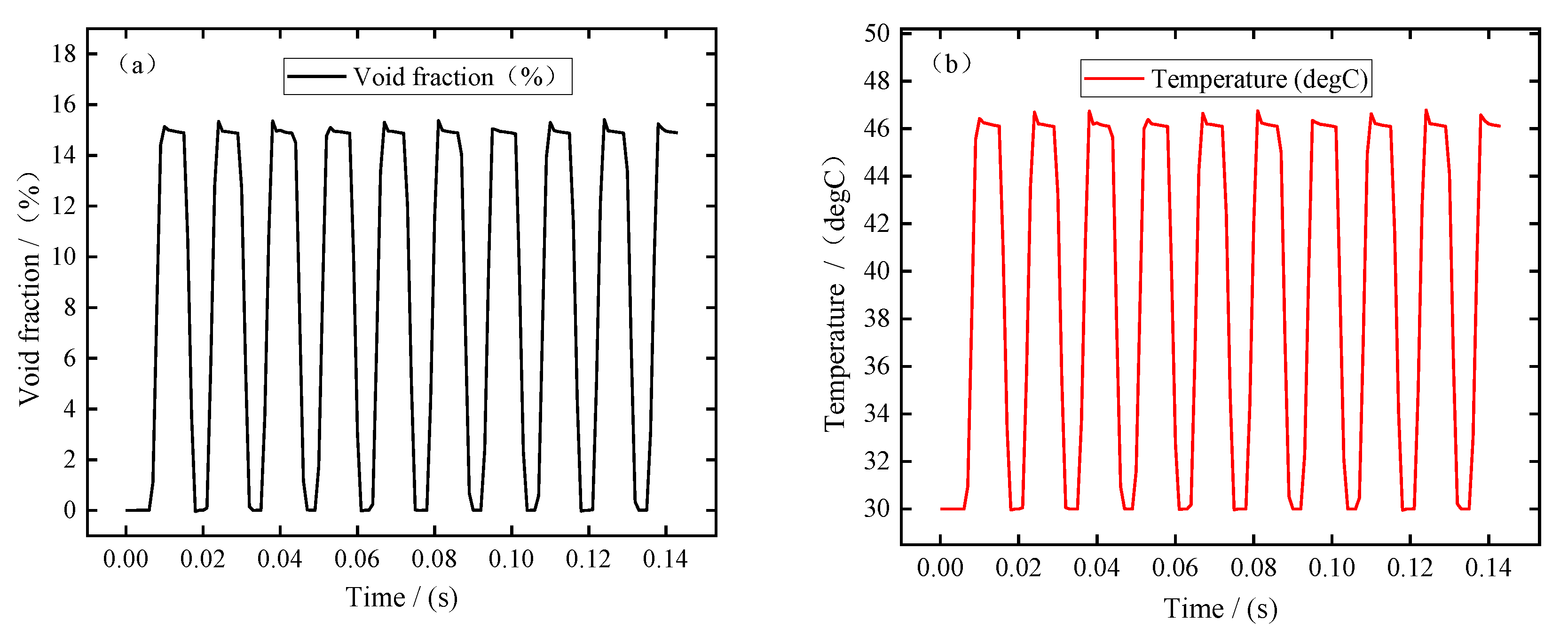
In this simulation, the pulse period is about 0.0143 s, the pulse-on time is 0.0086 s, and the pulse-off time is 0.0057 s. In order to better analyze the changes in electrolytic products during machining, the simulation results of ten pulse cycles were recorded when the machining was in equilibrium state. Figure 3 shows the changes in bubble volume fraction, electrolyte temperature, electrolyte flow rate, and electrical conductivity at the electrolyte outlet (Boundary 7) with the processing time. It can be seen from Figure 3a,b that the bubble volume fraction and electrolyte temperature at the outlet show a similar variation trend; that is, the bubble volume fraction and temperature increase rapidly, remain almost constant after the end of the pulse-off, and then decrease rapidly after the end of the pulse-on. It can be seen from Figure 3c that the electrolyte flow rate increases slightly at the pulse-on stage. This is mainly related to the formation of bubbles in the machining gap, which has a certain promoting effect on the flow rate of electrolyte. It can be seen from Figure 3d that the electrical conductivity increases rapidly at the pulse-on stage. According to Equation (25), this means that the influence of electrolyte temperature on electrical conductivity is more dominant than that of bubble concentration. In addition, it can be seen from these figures that due to the pulse-off stage in pulse ECM, the electrolytic products can be discharged completely before the next pulse is energized, so that the electrolyte in the machining gap is updated and the electrolyte conductivity is maintained constant. This is beneficial to improving blade surface quality and machining accuracy, which is also an advantage of pulse ECM.
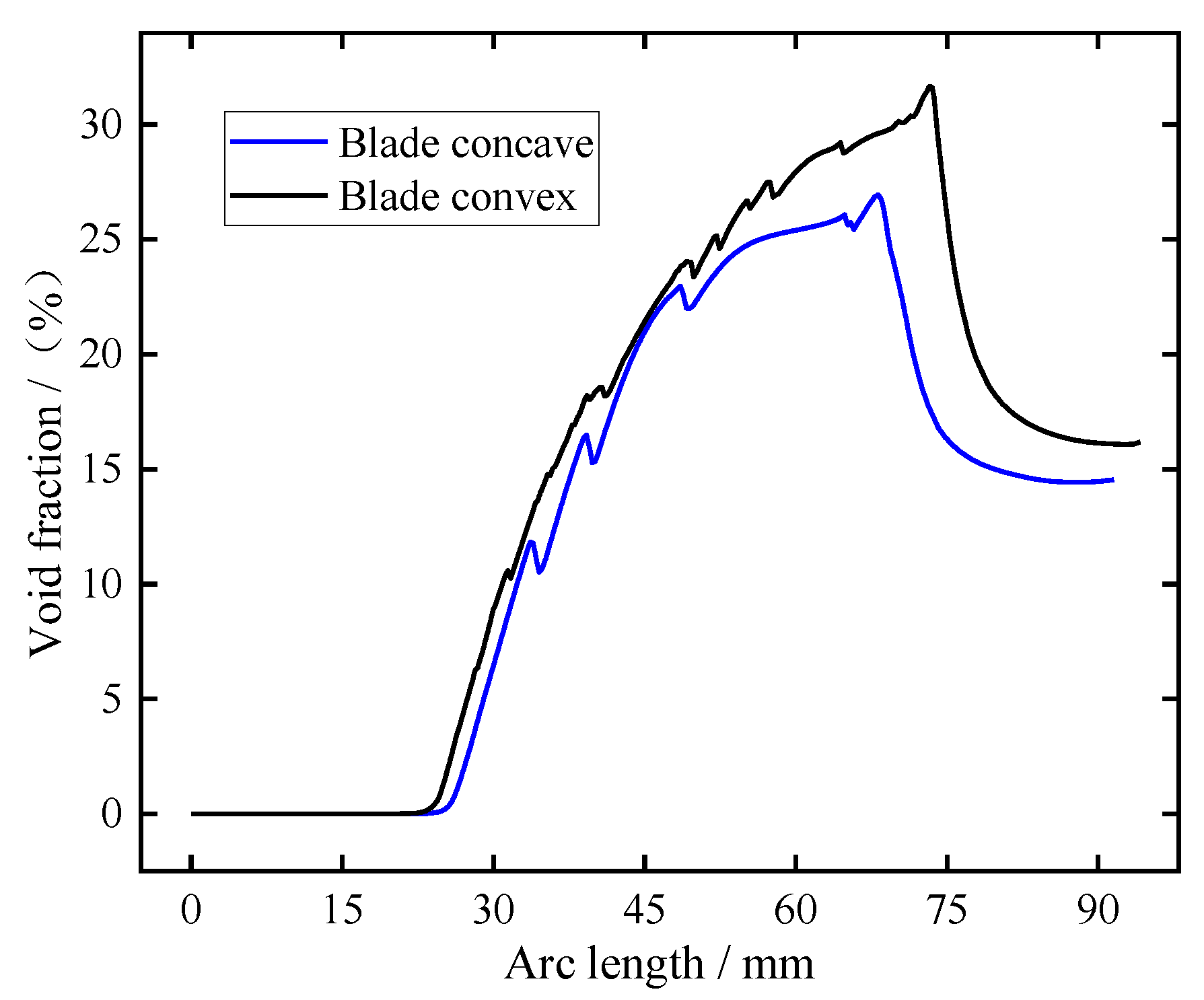
During the process, the H+ on the cathode surface is reduced to hydrogen, and the distribution of these hydrogen bubbles along the cathode surface is very different under the action of the high-speed flow of electrolyte in the machining gap. In order to better analyze the distribution of bubbles along the cathode surface, the corresponding bubble volume fraction at the pulse-on moment t = 0.01 s was recorded, as shown in Figure 4. It can be seen from the figure that the bubble volume fraction is 0 because there is no corresponding anode in the inlet diversion section. With the increase in arc length, the volume fraction of bubbles on the cathode surface increases gradually. The maximum bubble volume fraction of the blade convex and the blade concave near the trailing edge is about 26% and 31%, respectively. Then it enters the outlet diversion section and flows out of the outlet. As the gap at the outlet diversion section becomes larger and the outlet diversion section is very long, the bubble volume fraction shows a trend of gradually decreasing first and then staying basically unchanged.
In order to more intuitively observe the distribution of electrolytic products in the machining gap at the pulse-on stage, the distribution cloud diagram of electrolytic products at t = 0.01 s was selected, as shown in Figure 5. It can be clearly seen from Figure 5a,b that the bubble volume fraction and electrolyte temperature in the machining gap gradually increase along the flow channel, with the highest bubble volume fraction reaching about 31% and the temperature increasing by about 20 °C. Figure 5c shows that the flow rate of electrolyte is very high and uniform in the machining gap, which is conducive to the discharge of electrolytic products and the timely update of electrolyte. It can be seen from Figure 5d that the value of electrical conductivity near the cathode surface is less than that at the initial moment (16.1 S/m), which is mainly caused by the accumulation of bubbles near the cathode surface. The conductivity of electrolyte in other regions gradually increases along the flow channel, which is mainly related to the increase in electrolyte temperature.
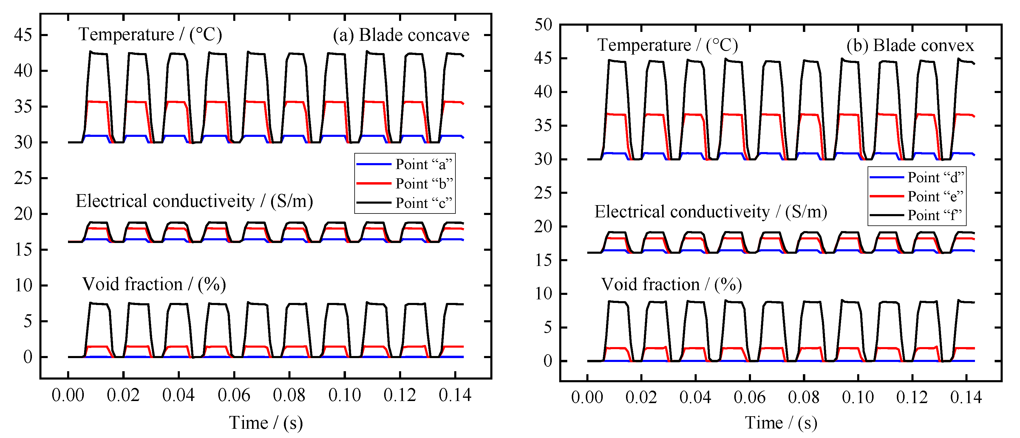
In the ECM of large size TiAl alloy blade, the distribution of electrolytic products on the blade surface is also very important. Therefore, the distribution of electrolytic products along the anode surface and the variation of different regions with the processing time were analyzed in detail. Three sampling points were selected on the surfaces of blade concave and blade convex near the leading edge area, the middle area, and the trailing edge area, respectively, as shown in Figure 2. Figure 6a,b recorded the change of void fraction, temperature, and electrolyte electrical conductivity at these sampling points on the surfaces of blade concave and blade convex, respectively. In general, blade concave and blade convex show similar patterns of change. It can be seen that with the periodic change of pulse current, the void fraction, temperature, and electrolyte electrical conductivity at the sampling point on the blade surface also show periodic changes. It can also be seen that from the leading edge area to the trailing edge area, the void fraction, temperature, and electrolyte electrical conductivity at the sampling point on the blade surface are increasing. Additionally, because of the influence of the accumulation along the flow channel, the growth rate of the stage from the leading edge region to the middle region is obviously smaller than that from the middle region to the trailing edge region. It is worth noting that the increase rate of the conductivity of the electrolyte shows a situation opposite to the void fraction and temperature. This is mainly because the content of the void fraction from the leading edge region to the middle region is small and the growth rate is slow, while the temperature increases quickly, making the electrolyte’s electrical conductivity increase rapidly. Then, from the middle region to the trailing edge region, the increase rate of void fraction is obviously faster than the increase rate of temperature, so that the increase rate of electrolyte electrical conductivity decreases. Moreover, it is obvious from Figure 6 that the void fraction, temperature, and electrolyte electrical conductivity at the three sampling points on the blade convex are always higher than those at the three sampling points on the blade concave. This is mainly due to the blade convex having a longer flow channel and a more distorted profile relative to the blade concave.
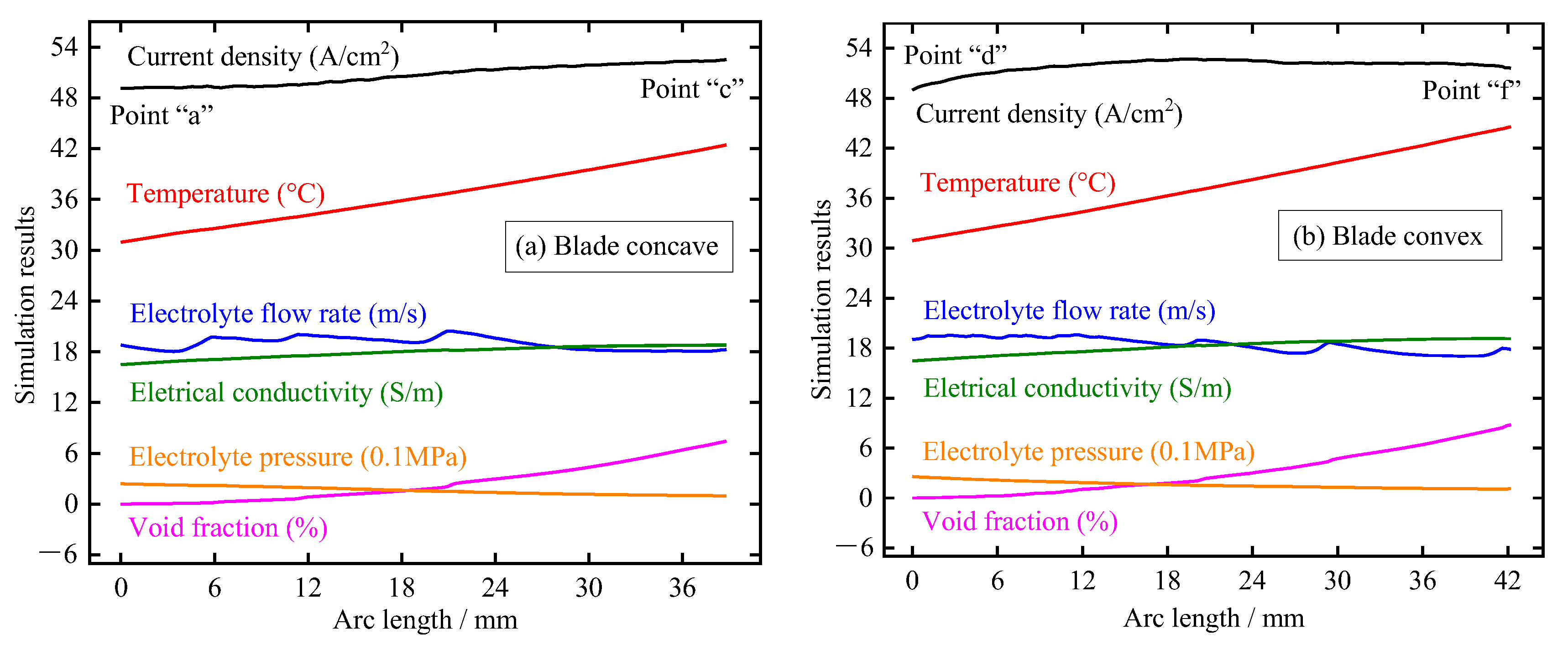
Figure 7 shows the distribution of electrolytic products along the blade surface at t = 0.01 s, including void fraction, electrolyte pressure, electrolyte electrical conductivity, electrolyte flow rate, temperature, and current density. The main findings here are as follows: (1) the electrolyte pressure gradually decreases with the increase of the length of the flow channel, which is mainly due to the loss along the channel caused by the resistance of the channel side wall; (2) the temperature of the electrolyte shows a trend of linear increase along the direction of the flow channel due to the increase of current density and accumulation along the path; (3) the void fraction on the blade surface increases gradually along the direction of the flow channel and has a higher growth rate near the trailing edge. This is mainly because the bubble accumulation is faster due to the decrease in electrolyte pressure and the specific volume of the bubble increases due to the increase in temperature; (4) the flow rate of electrolyte fluctuates slightly and decreases with the increase in the flow channel. This may be because the profile of the large TiAl alloy blade is very twisted, resulting in obvious flow direction changes between the front and back parts of the blade; (5) the electrical conductivity gradually increases along the direction of the flow channel, which indicates that the influence of electrolyte temperature on conductivity is more dominant than that of bubble concentration; and (6) the current density on the blade surface increases gradually with the increase of the length of the flow channel, and the growth rate in the area near the trailing edge slows down significantly due to the obvious increase of the void fraction. It can be seen that for the large size TiAl alloy blade, due to its long flow channel and distorted profile, the corresponding electrolytic product distribution is very complex, and the accumulation effect is more serious.
Based on the above multi-physical field coupling simulation analysis, the distribution laws of electrolytic products of large size TiAl alloy blade along the flow channel in the machining gap are mastered. The results have important guiding significance for the accurate design of tool electrode profiles, the selection of ECM parameters, and the interpretation of machining phenomena for large size TiAl alloy blade. For the design of the tool cathode surface, the electrolyte conductivity along the direction of the electrolyte flow has been obtained. The tool cathode surface of large size TiAl alloy blade can be designed more accurately based on the forming rules of ECM so as to reduce the number of cathode corrections and obtain high machining accuracy. For the selection of ECM parameters, if the selection is not reasonable, it may lead to short-circuit burn in the ECM, resulting in machining interruption and tool cathode and blade damage. In the above study, the ECM parameters of large size TiAl alloy blade was preliminarily optimized and verified by simulation, which avoided some defects in the actual machining process and saved a lot of time and money. In fact, many other ECM parameters have been simulated, but the results are not satisfactory. It is not discussed in view of space constraints.
In the next section, based on the above simulation studies, the large size TiAl alloy blade will be manufactured using a precisely designed tool cathode and preferred ECM parameters, and the machining process, surface roughness, and machining errors will be analyzed and measured.

5. Experiments and Discussion

5.1. Pulse ECM of Large Size TiAl Alloy Blade

In this part, pulse ECM experiments on large size TiAl alloy blade were carried out. A self-developed ECM system was established, including a large ECM machining tool, a high-power pulse power supply, and a special fixture for large size TiAl alloy blade. The ECM machining tool consists of two horizontal axes and one vertical axis, and the movement and position of the cathode axis are precisely controlled by the numerical control system. The maximum output voltage and current of the pulse power supply can reach 38 V and 13,440 A, respectively, and the adjustment range of pulse frequency is 0–2000 Hz. Due to the large size of the ECM fixture, the material of its main support part is stainless steel to prevent deformation. Other parts of the fixture are made of epoxy resin for insulation. Figure 8 shows the 3D model of the ECM fixture.
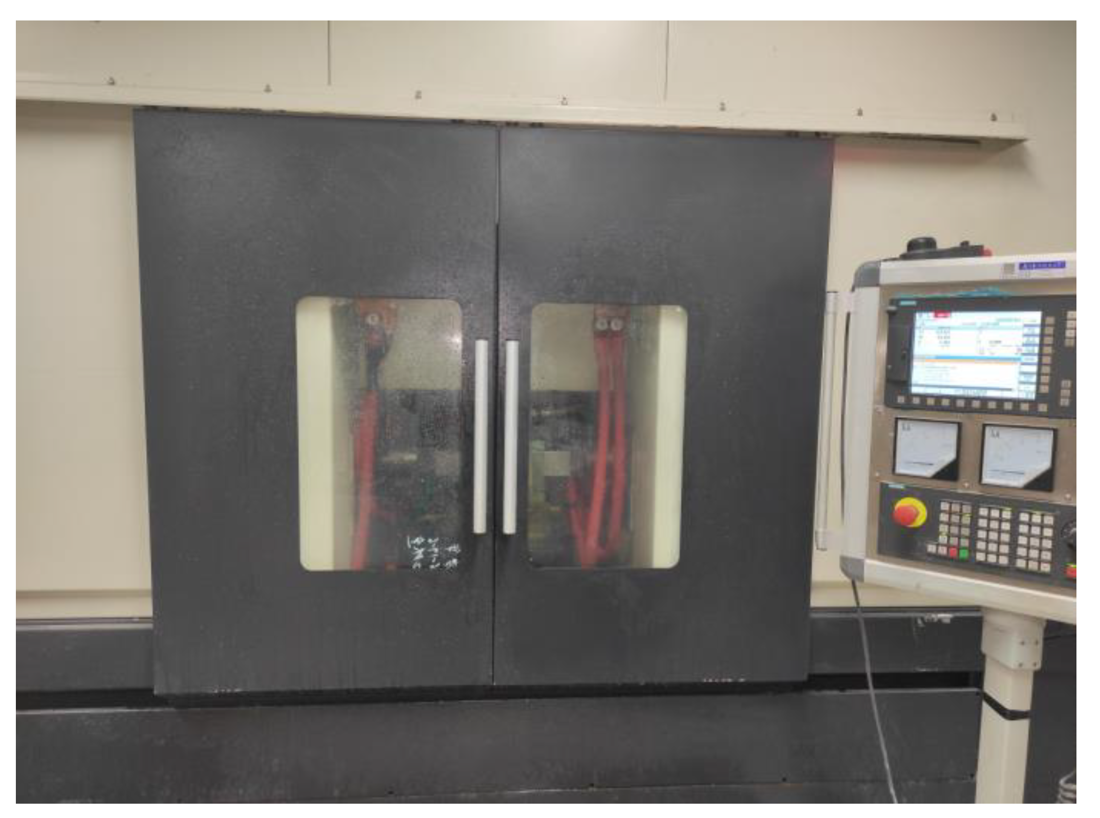
After a large number of exploratory experiments, the machining of large size TiAl alloy blade can be divided into two continuous steps; that is, after the first step is finished, only some machining parameters need to be changed before the second step can be started. There is no need to reinstall the workpiece during this two-step process, which can avoid repeated installation errors. Detailed machining parameters are listed in Table 2 [30]. Figure 9 shows the ECM of large size TiAl alloy blade in the machining area of the machining tool.

5.2. Analysis of Experimental Results

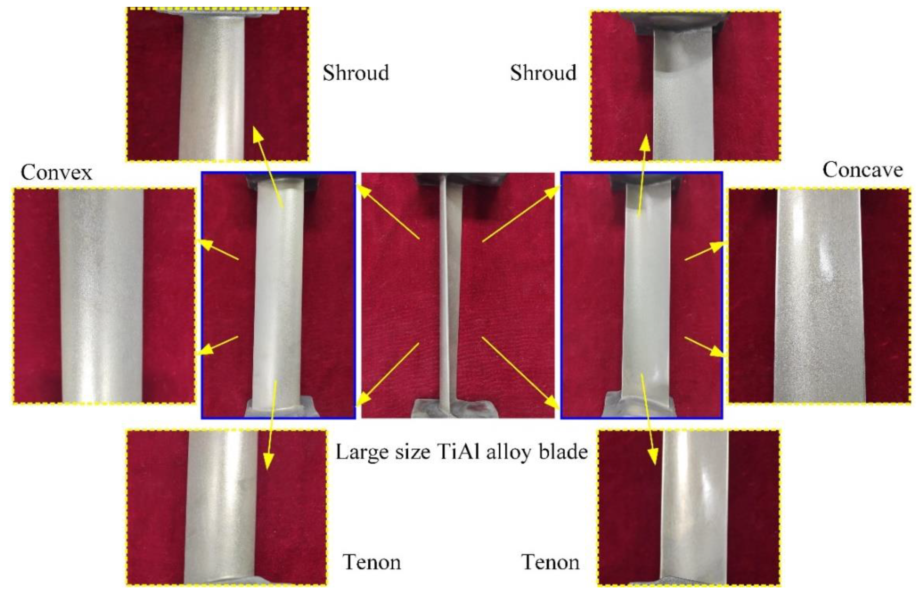
Figure 10 shows the large size TiAl alloy blade machined by pulse ECM. The whole process is very stable, and there is no interruption. The total processing time of a blade is only about 17.8 min, and the total material volume removal rate is about 10,393 mm3/min. It can be seen that the ECM of large size TiAl alloy blade has very high machining efficiency, which is very suitable for the manufacture of this kind of blade. The surface quality and machining accuracy of the blades will also be analyzed in detail.
The variation of the average machining current with the cathode feed distance during the ECM of large size TiAl alloy blade was recorded, as shown in Figure 11. It can be clearly seen from the figure that with the increase in cathode feed distance, the average machining current gradually increases. When the feed distance is about 8 mm, the average machining current hardly changes, indicating that the machining enters the equilibrium state. The average machining current in the equilibrium state is about 4360 A. When the feed distance is about 11.4 mm, the first step is finished, and the second step is started. The average machining current rose sharply to about 4700 A. This is mainly because the processing voltage and cathode feed speed increase in the second step. It can also be seen from the figure that there is no sudden change in the average processing current during the whole machining process. This means that the whole process is very stable; there is no short-circuit phenomenon.
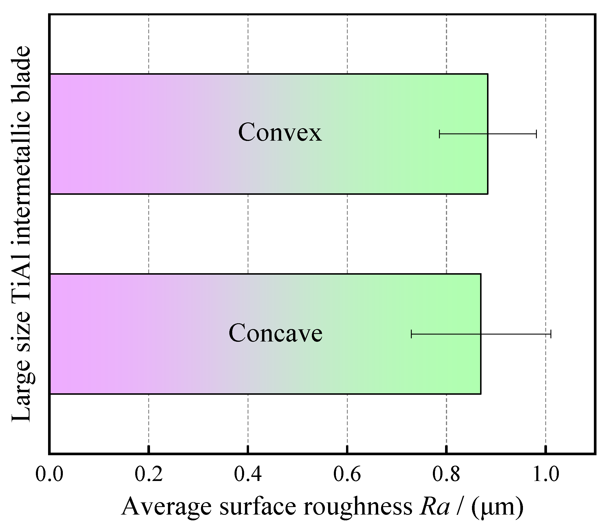
The surface roughness of the blade was measured by a surface roughness meter (Perthometer M1, Mahr GmbH, Göttingen Germany). In order to ensure the reliability of surface roughness measurement, six measuring lines were selected on the surfaces of blade concave and blade convex, respectively, and then the average value was taken. The measured length of each measuring line is 5.6 mm, and the effective length is 4 mm. Figure 12 shows the calculation results for the average surface roughness of the processed blade. It can be seen from Figure 12 that the average surface roughness of blade concave and blade convex is about Ra 0.9 μm, and the surface is very smooth. This can also be verified in Figure 10. The above results show that the large size TiAl alloy blade machined by pulse ECM has high surface quality and no defects such as flow marks on the surface.
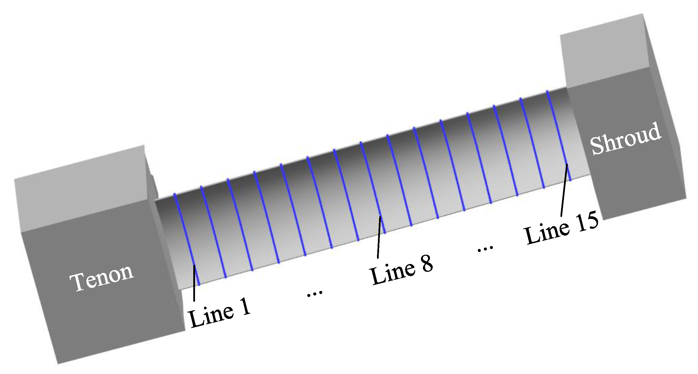
The machining accuracy of the blade is also an important index to evaluate the machining effect. For large size TiAl alloy blade, it is required to select 15 control lines on the blade concave and blade convex surfaces, respectively, to measure the machining error. Figure 13 shows the positions of 15 measurement lines selected on the surface of the blade concave, and the positions of measurement lines on the surface of the blade convex are similar. Figure 14a,b show the measuring results of machining errors of blade concave and blade convex by a coordinate measuring machine (Sweden, Hexagon). It can be clearly seen that the machining error of the 30 measuring lines on the surface of the blade concave and blade convex is about 0.18 mm, indicating that the large size TiAl alloy blade has very high machining accuracy. The above measurement results also indicate that the precision manufacturing of large size TiAl alloy blade can be realized by pulse ECM.

6. Conclusions

In this paper, multi-physical field coupling simulation and experiments of pulse ECM on large size TiAl alloy blade were studied. The geometric and theoretical simulation models of multiple physical field couplings were established. The distribution laws of electrolytic products along the flow channel were mastered. High efficiency and precision manufacturing of large size TiAl alloy blade were realized. The conclusions of this work are summarized as follows:
The multi-physical field coupling simulation geometry and theoretical models of large size TiAl alloy blade involving electric field, gas-liquid two-phase flow, heat transfer, and anode dissolution were established.
The variation laws of bubble, temperature, electrolyte flow rate, and electrical conductivity at the outlet and the different areas on the blade surface with the processing time and the distribution law along the flow channel in the machining gap were mastered. It is found that the influence of electrolyte temperature on electrical conductivity is more dominant than that of bubble concentration.
Large size TiAl alloy blade with high surface quality and high machining accuracy was obtained by pulse ECM. The average surface roughness and machining error of the blade are about Ra 0.9 μm and 0.18 mm, respectively.

Author Contributions

Methodology, investigation, data curation, experimental, manuscript—writing and funding acquisition, Y.W.; manuscript—review and editing, supervision, and funding acquisition, Z.X.; investigation, data curation, and experimental, D.M.; investigation, data curation, and experimental, L.L.; investigation and experimental, Z.F. All authors have read and agreed to the published version of the manuscript.

Funding

This research was sponsored by the National Natural Science Foundation of China [grant number 91960204], the China Postdoctoral Science Foundation [grant number 2022M721603], and the National Natural Science Foundation of China for Creative Research Groups [grant number 51921003].

Data Availability Statement

All data generated or analyzed during this study are included in this article.

Conflicts of Interest

The authors declare no conflict of interest.

References

  1. Kothari, K.; Radhakrishnan, R.; Wereley, N.M. Advances in gamma titanium aluminides and their manufacturing techniques. Prog. Aerosp. Sci. 2012, 55, 1–16. [Google Scholar] [CrossRef]
  2. Bewlay, B.P.; Weimer, M.; Kelly, T.; Suzuki, A.; Subramanian, P. The science, technology, and implementation of TiAl alloys in commercial aircraft engines. MRS Proc. 2013, 1516, 49–58. [Google Scholar] [CrossRef]
  3. Rajurkar, K.; Zhu, D.; McGeough, J.; Kozak, J.; De Silva, A. New developments in electro-chemical machining. CIRP Ann.-Manuf. Technol. 1999, 48, 567–579. [Google Scholar] [CrossRef]
  4. Xu, Z.; Wang, Y. Electrochemical machining of complex components of aero-engines: Developments, trends, and technological advances. Chin. J. Aeronaut. 2021, 34, 28–53. [Google Scholar] [CrossRef]
  5. Liu, J.; Hui, L.; Jia, D.; Liu, Y.; Zhu, D. An electrochemical machining method for aero-engine blades based on four-directional synchronous feeding of cathode tools. Chin. J. Aeronaut. 2022. [Google Scholar] [CrossRef]
  6. Schaarschmidt, I.; Luther, F.; Steinert, P.; Richter, M.; Schubert, A. Simulation of the magnetic field assisted electrochemical machining. Procedia CIRP 2023, 117, 249–256. [Google Scholar] [CrossRef]
  7. Wang, J.; Xu, Z.; Wang, J.; Xu, Z.; Zhu, D. Electrochemical machining of blisk channels with rotations of the cathode and the workpiece. Int. J. Mech. Sci. 2021, 208, 106655. [Google Scholar] [CrossRef]
  8. Clifton, D.; Mount, A.; Jardine, D.; Roth, R. Electrochemical machining of gamma titanium aluminide intermetallics. J. Mater. Process. Technol. 2001, 108, 338–348. [Google Scholar] [CrossRef]
  9. Liu, J.; Zhu, D.; Zhao, L.; Xu, Z. Experimental investigation on electrochemical machining of γ-TiAl intermetallic. Procedia CIRP 2015, 35, 20–24. [Google Scholar] [CrossRef]
  10. Baehre, D.; Ernst, A.; Weißhaar, K.; Natter, H.; Stolpe, M.; Busch, R. Electrochemical dissolution behavior of titanium and titanium-based alloys in different electrolytes. Procedia CIRP 2016, 42, 137–142. [Google Scholar] [CrossRef]
  11. Klocke, F.; Herrig, T.; Zeis, M.; Klink, A. Comparison of the electrochemical machinability of electron beam melted and casted gamma titanium aluminide TNB-V5. Proc. Inst. Mech. Eng. Part B J. Eng. Manuf. 2018, 232, 586–592. [Google Scholar] [CrossRef]
  12. Wang, Y.; Xu, Z.; Zhang, A. Electrochemical dissolution behavior of Ti-45Al-2Mn-2Nb+0.8 vol% TiB2 XD alloy in NaCl and NaNO3 solutions. Corros. Sci. 2019, 157, 357–369. [Google Scholar] [CrossRef]
  13. Wang, Y.; Xu, Z.; Zhang, A. Anodic characteristics and electrochemical machining of two typical γ-TiAl alloys and its quantitative dissolution model in NaNO3 solution. Electrochimica Acta 2020, 331, 135429. [Google Scholar] [CrossRef]
  14. Wang, Y.; Xu, Z.; Zhang, A.; Xu, G.; Zhang, C. Surface morphology and electrochemical behaviour of Ti-48Al-2Cr-2Nb alloy in low-concentration salt solution. Sci. China Technol. Sci. 2021, 64, 283–296. [Google Scholar] [CrossRef]
  15. Klocke, F.; Zeis, M.; Klink, A. Interdisciplinary modelling of the electrochemical machining process for engine blades. CIRP Ann.-Manuf. Technol. 2015, 64, 217–220. [Google Scholar] [CrossRef]
  16. Klocke, F.; Zeis, M.; Harst, S.; Klink, A.; Veselovac, D.; Baumgärtner, M. Modeling and simulation of the electrochemical machining (ECM) material removal process for the manufacture of aero engine components. Procedia CIRP 2013, 8, 265–270. [Google Scholar] [CrossRef]
  17. Wang, H.; Zhu, D.; Liu, J. Improving the accuracy of the blade leading/trailing edges by electrochemical machining with tangential feeding. CIRP Ann.-Manuf. Technol. 2019, 68, 165–168. [Google Scholar] [CrossRef]
  18. Schaarschmidt, I.; Hackert-Oschätzchen, M.; Meichsner, G.; Zinecker, M.; Schubert, A. Implementation of the machine tool-specific current and voltage control characteristics in multiphysics simulation of electrochemical precision machining. Procedia CIRP 2019, 82, 237–242. [Google Scholar] [CrossRef]
  19. Chen, Y.; Zhou, X.; Chen, P.; Wang, Z. Electrochemical machining gap prediction with multi-physics coupling model based on two-phase turbulence flow. Chin. J. Aeronaut. 2020, 33, 1057–1063. [Google Scholar] [CrossRef]
  20. Wang, F.; Yao, J.; Kang, M. Electrochemical machining of a rhombus hole with synchronization of pulse current and low-frequency oscillations. J. Manuf. Process. 2020, 57, 91–104. [Google Scholar] [CrossRef]
  21. Wang, Y.; Xu, Z.; Liu, J.; Zhang, A.; Xu, Z.; Meng, D.; Zhao, J. Study on flow field of electrochemical machining for large size blade. Int. J. Mech. Sci. 2021, 190, 106018. [Google Scholar] [CrossRef]
  22. Fujisawa, T.; Inaba, K.; Yamamoto, M.; Kato, D. Multiphysics simulation of electrochemical machining process for three-dimensional compressor blade. J. Fluids Eng. 2008, 130, 0816021–0816028. [Google Scholar] [CrossRef]
  23. Wang, M.; Liu, W.; Peng, W. Multiphysics research in electrochemical machining of internal spiral hole. Int. J. Adv. Manuf. Technol. 2014, 74, 749–756. [Google Scholar] [CrossRef]
  24. Fang, X.; Qu, N.; Zhang, Y.; Xu, Z.; Zhu, D. Effects of pulsating electrolyte flow in electrochemical machining. J. Mater. Process. Technol. 2014, 214, 36–43. [Google Scholar] [CrossRef]
  25. Zong, Y.; Liu, J.; Zhu, D. Improving blade accuracy via local electrochemical machining with partial insulated cathodes. Precis. Eng. 2022, 76, 284–293. [Google Scholar] [CrossRef]
  26. Wang, M.; Zhang, R.; Shang, Y.; Zheng, J.; Wang, X.; Xu, X. Micro-milling microstructures in air-shielding ultrasonic assisted electrochemical machining. J. Manuf. Process. 2023, 97, 171–184. [Google Scholar] [CrossRef]
  27. Jiao, E.; Zhu, D.; Zhang, C.; Wang, P.; Zuo, H. Research on the characteristics of multiphysics coupling fields in the electrochemical trepanning of an inward facing blisk. J. Manuf. Process. 2023, 93, 60–74. [Google Scholar] [CrossRef]
  28. He, C.Y. Multiphysics simulation of electrochemical machining process. Master’s Thesis, Guangdong University of Technology, Guangzhou, China, 2015. [Google Scholar]
  29. Jiang, C. Product distribution and parameter optimization in pulsating electrochemical machining. Master’s Thesis, Nanjing University of Aeronautics and Astronautics, Nanjing, China, 2019. [Google Scholar]
  30. Wang, Y.; Xu, Z.; Meng, D.; Liu, L.; Fang, Z. Study on surface roughness of large size TiAl intermetallic blade in electrochemical machining. J. Manuf. Process. 2022, 76, 1–10. [Google Scholar] [CrossRef]
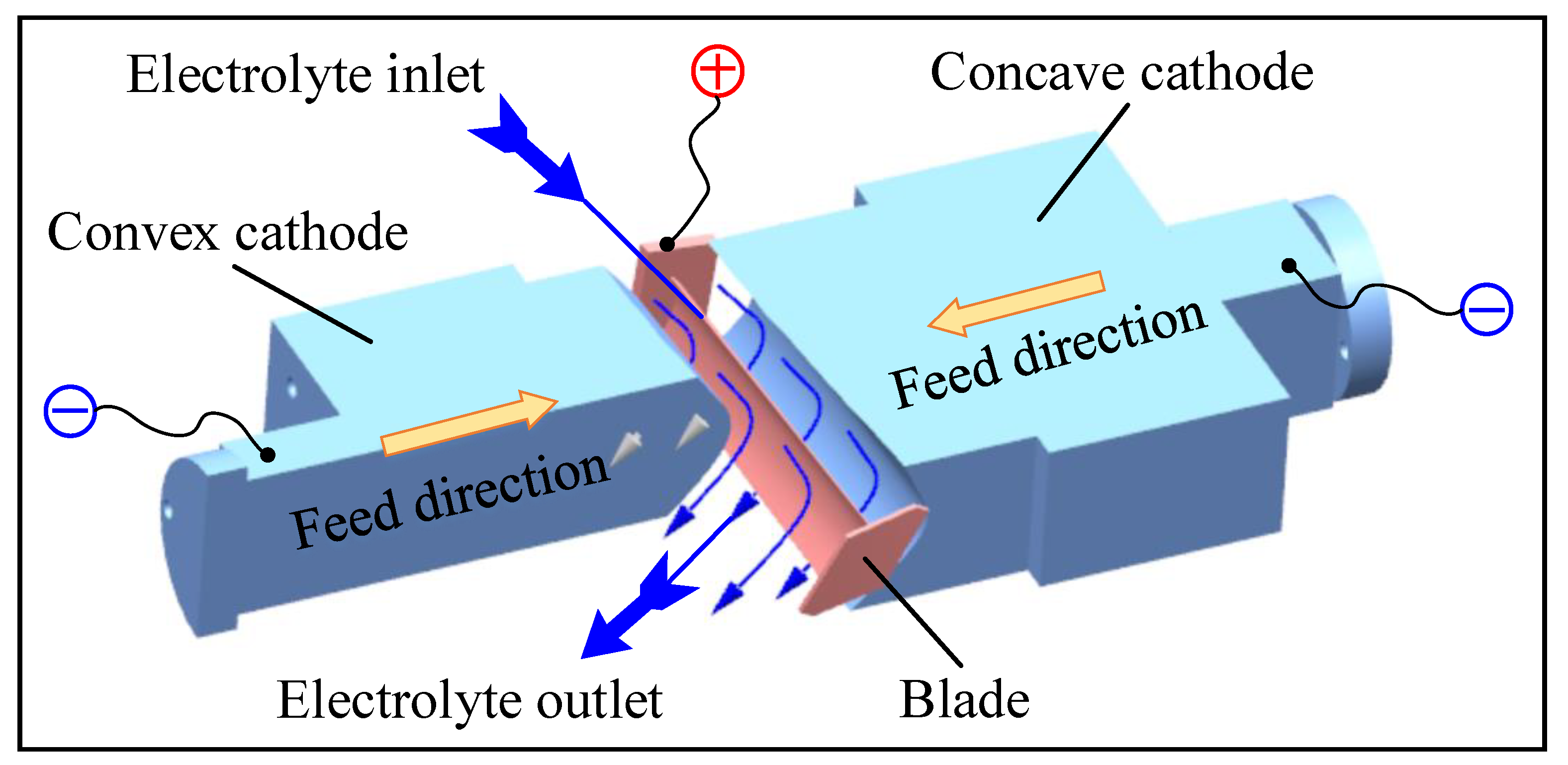
Figure 1. Schematic diagram of the ECM of large size TiAl alloy blade.
Metals 13 00985 g001
Figure 2. Schematic diagram of the simulation model of multi-physical field coupling for the ECM of large size TiAl alloy blade.
Metals 13 00985 g002
Figure 3. The electrolytic products change with the processing time at the outlet (Boundary 7): (a) void fraction, (b) temperature, (c) electrolyte flow rate, and (d) electrical conductivity.
Metals 13 00985 g003aMetals 13 00985 g003b
Figure 4. The distribution of bubbles on the cathode surface along the flow channel at the pulse-on stage (t = 0.01 s).
Metals 13 00985 g004
Figure 5. Distribution cloud diagram of electrolytic products in the machining gap at pulse-on (t = 0.01 s): (a) void fraction, (b) temperature, (c) electrolyte flow rate, and (d) electrical conductivity.
Metals 13 00985 g005
Figure 6. The variation of void fraction, temperature, and electrical conductivity in different areas of the blade surface with machining time: (a) blade concave, and (b) blade convex.
Metals 13 00985 g006
Figure 7. Distribution of electrolytic products on blade surface at pulse-on (t = 0.01 s): (a) blade concave and (b) blade convex.
Metals 13 00985 g007
Figure 8. Three-dimensional model of the ECM fixture.
Metals 13 00985 g008
Figure 9. Pulse ECM of large size TiAl alloy blade.
Metals 13 00985 g009
Figure 10. Large size TiAl alloy blade machined by pulse ECM.
Metals 13 00985 g010
Figure 11. The average machining current changes with the feed distance.
Metals 13 00985 g011
Figure 12. Average surface roughness of large size TiAl alloy blade.
Metals 13 00985 g012
Figure 13. Schematic diagram of the selection of measuring lines for large size TiAl alloy blade.
Metals 13 00985 g013
Figure 14. Machining error of large size TiAl alloy blade: (a) concave and (b) convex.
Metals 13 00985 g014
Table 1. Simulation parameters for pulse ECM of large size TiAl alloy blade.
ParametersValues
Workpiece materialTiAl 45XD
Cathode material1Cr18Ni9Ti
Cathode feeding rate vc (mm/min)0.65
Electrolyte concentration20% NaNO3
Electrolyte initial conductivity κ (S/m)16.1
Voltage U (V)26
Pulse duty60%
Pulse frequency f (Hz)70
Inlet pressure P1 (MPa)0.4
Outlet pressure P2 (MPa)0.1
Electrolyte temperature T (°C)30
Table 2. Machining parameters for the pulse ECM of large size TiAl alloy blade.
ParametersValues
First StepSecond Step
Cathode feeding rate vc (mm/min)0.651.6
Electrolyte concentration20% NaNO3
Voltage U (V)2630
Pulse duty60%
Pulse frequency f (Hz)7050
Inlet pressure Pin (MPa)0.6, 0.4, 0.41.2, 1.0, 1.0
Outlet pressure Pout (MPa)0.1
Electrolyte temperature T (°C)30
Cathode feeding depth (mm)11.40.5
Disclaimer/Publisher’s Note: The statements, opinions and data contained in all publications are solely those of the individual author(s) and contributor(s) and not of MDPI and/or the editor(s). MDPI and/or the editor(s) disclaim responsibility for any injury to people or property resulting from any ideas, methods, instructions or products referred to in the content.