Article

Detection of Phase Transformation during Plastic Deformation of Metastable Austenitic Steel AISI 304L by Means of X-ray Diffraction Pattern Analysis

1
Chair of Materials Test Engineering (WPT), TU Dortmund University, 44227 Dortmund, Germany
2
Forming and Machining Technology (LUF), Paderborn University, 33098 Paderborn, Germany
3
Fraunhofer Institute for Mechatronic Systems Design (IEM), 33102 Paderborn, Germany
*
Author to whom correspondence should be addressed.
Metals 2023, 13(6), 1007; https://doi.org/10.3390/met13061007
Submission received: 30 March 2023 / Revised: 19 May 2023 / Accepted: 19 May 2023 / Published: 23 May 2023
(This article belongs to the Special Issue Deformation and Failure Behavior of Metastable Metallic Materials)

Abstract

:
This paper evaluates the suitability of the X-ray diffraction (XRD) technique to characterize the phase transformation during the metal forming of the metastable austenitic steel AISI 304L. Due to plastic deformation, phase transformation from γ-austenite into α′-martensite occurs. The XRD peaks at specific 2θ diffraction angles give information about the phase amount. Analyses of the results with different characterization techniques such as microscopic analysis, including electron backscatter diffraction (EBSD), macro- and microhardness tests and magneto-inductive measurements of α′-martensite, were carried out. A qualitative and quantitative correlation to compute the amount of α′-martensite from the XRD measurements was deduced. XRD was validated as a suitable technique to characterize the phase transformation of metastable austenites. Additional data could provide necessary information to develop a more reliable model to perform a quantitative analysis of the phases from XRD measurements.

1. Introduction

Flow forming is a metal spinning process that has recently gained relevance in areas such as the automotive and aerospace industries, due to manufacturing flexibility, resource optimization and the possibility of producing near-net-shape components. The use of metastable austenitic stainless steel in combination with advanced manufacturing techniques makes the production of high-performance products possible [1]. During the forming of metastable austenites, plastic deformation simultaneously changes the geometrical characteristics and the microstructure of the specimens. In the specific case of the austenitic stainless steel 304L, the microstructural evolution involves changes in the magnetic and mechanical properties [2]. This investigation focuses on the evaluation of the suitability of the X-ray diffraction (XRD) method to characterize microstructure evolution, particularly with respect to strain-hardening and phase transformation during plastic deformation. These results will be correlated with alternative characterization techniques such as magneto-inductive measurements of α′-martensite amount, hardness tests and scanning electron microscopy (SEM) analysis, including Electron Backscatter Diffraction (EBSD).
XRD is a technique mainly used to characterize the stress state [3] and especially the residual stresses [4,5,6] of materials for engineering applications. Recent investigations have focused on the residual stress assessment of deep rolled and microfinished AISI 4140 components with the novel time-efficient cos α-method instead of the sin2ψ method [7]. By means of high-energy synchrotron X-ray diffraction, phase-specific stresses were calculated using dhkl-sin2ψ distributions from recorded Debye–Scherrer rings [8]. A combination of microstructural analysis by means of EBSD and the residual stress state of the welded seams of austenitic stainless steels tubes have been carried out in [9] by XRD. Similarly, a microstructural characterization, including hardness tests and XRD analysis, was depicted on electron beam welded joints of low carbon Ni-Cr-Mo alloy steels [10]. In combination with several microstructural characterization techniques, such as scanning and transmission electron microscopy, XRD has been used to characterize novel microstructural features of low-activation chromium–manganese austenitic steel, specifically regarding structure, dislocation character and particle composition [11]. Other uses of XRD include the analysis of textures [12,13]. Recently, the evolution of textures during the phase transformation of silicon steels has been characterized using in situ XRD and EBSD [14]. Other researchers have also conducted microstructural characterization by means of microscopical techniques, combined with residual stress and texture measurements using XRD at specific depth positions on radial forged high-strength alloy steel tubes [15].
One of the most common applications of XRD is the qualitative and quantitative phase analysis [16]. Some investigations have used XRD to study martensite and austenite phase amounts in stainless steels wires before and after deformation [17]. Further investigations carried out XRD measurements on austenitic stainless steel AISI 304 to perform a quantitative phase analysis of deformation-induced martensite, based on the evolution of microstructural features such as grain size [18]. Talonen et al. also performed XRD measurements, among other characterization techniques, to validate the strain induced α′-martensite content in austenitic steel [19]. Recently, investigations have focused on the quantitative phase analysis of maraging steel 13Ni15Co10Mo using XRD combined with Grazing Incidence XRD to characterize the austenite formation due to oxidation by layers [20]. Using a Bragg–Brentano configuration on an X-ray diffractometer, residual stresses and the phase transformation of austenitic stainless steels AISI 904L and AISI 347 were reported during the cyclic loading of specimens with different surface morphologies [21]. The martensite volume fraction of 316L stainless steel specimens were characterized during low cycle fatigue tests by means of in situ and ex situ neutron diffraction measurements in [22]. Tomota et al. performed a multi-technique characterization on heat-treated 1.5Mn-1.5Si-0.2C steels comparing neutron diffraction, XRD, EBSD and dilatometry measurements [23].
In this investigation, the characterization of phase transformation and strain-induced hardening during the flow forming of metastable austenite AISI 304L provides fundamental information for material behavior modeling. The material model details the evolution of material properties, specifically the amount of α′-martensite, depending on geometrical features such as wall thickness reduction and production parameters such as infeed depth and the feed rate of the rolling tool. The material behavior model plays an important role in the development of a closed-loop property control for the flow forming process, which is part of the overall goal of this research. Material behavior modeling needs correlations that evidence the evolution of properties during flow forming. This requires the implementation of multiple characterization techniques to reliably validate the microstructural phenomena involved. As mentioned, the amount of α′-martensite created from the plastic deformation of the initial metastable austenite will be characterized by means of macro- and microhardness tests, EBSD and XRD analysis.

2. Materials and Methods

2.1. Specimens

The specimens were produced by means of reverse flow forming (Figure 1a,b) at the Chair of Forming and Machining Technology of Paderborn University (LUF), using the machine BD 40 (Bohner & Koehle GmbH & Co. KG, Esslingen, Germany). The raw material of the workpieces are seamless tubes made of stainless steel AISI 304L (X2CrNi18-9, 1.4307) with an 80 mm outer diameter and a 4 mm wall thickness. The specimens were manufactured at room temperature, which was kept constant during the production by means of active cooling. The speed rotation of the spindle was 30 rpm and the feed rate of the forming tool was set between 6 and 60 mm/min. The focus will be put on specimens produced with feed rates of 6 mm/min (Specimen 1) and 60 mm/min (Specimen 2).
The flow forming operations were performed using three rollers to reduce the wall thickness of the tubes. The initial 4 mm wall thickness was reduced with infeed depths of 1, 2 and 3 mm in each flow forming step. Starting from the initial condition, “IC” (metastable austenite), flow forming operations were performed to produce three forming zones (FZ 1, 2 and 3) (Figure 1c). Each forming zone corresponds to a plastic deformation state with a defined amount of strain-induced α′-martensite. The final specimens manufactured during the production process are shown in Figure 1d.

2.2. Characterization Methodologies

2.2.1. X-ray Diffraction (XRD) Investigation

X-rays are high-energy electromagnetic waves. Due to their short wavelengths (bet-ween 0.001 and 10 nm), they are suitable for a wide range of applications in material characterization. The interaction of X-ray photons with matter leads to absorption or scattering effects. The coherent scattering, called Rayleigh scattering, occurs between photons and electrons surrounding the atomic nuclei. Due to the periodic nature of a crystalline structure, constructive or destructive scattering radiation produces characteristic radiation phenomena, which can be used to investigate the crystal structure of materials. The geometrical interpretation of XRD is represented by Bragg’s law (Equation (1)).
= 2dhkl sin(θ),
In Equation (1), n is the order of diffraction, λ is the wavelength of the incident beam, dhkl is the lattice spacing in nm and θ is the angle of the diffracted beam in degrees. Diffractions for each lattice plane and direction that satisfy Bragg’s law are constructive interferences. The diffraction data are represented as distributions of intensity in peaks per second as a function of the 2θ angle [24].
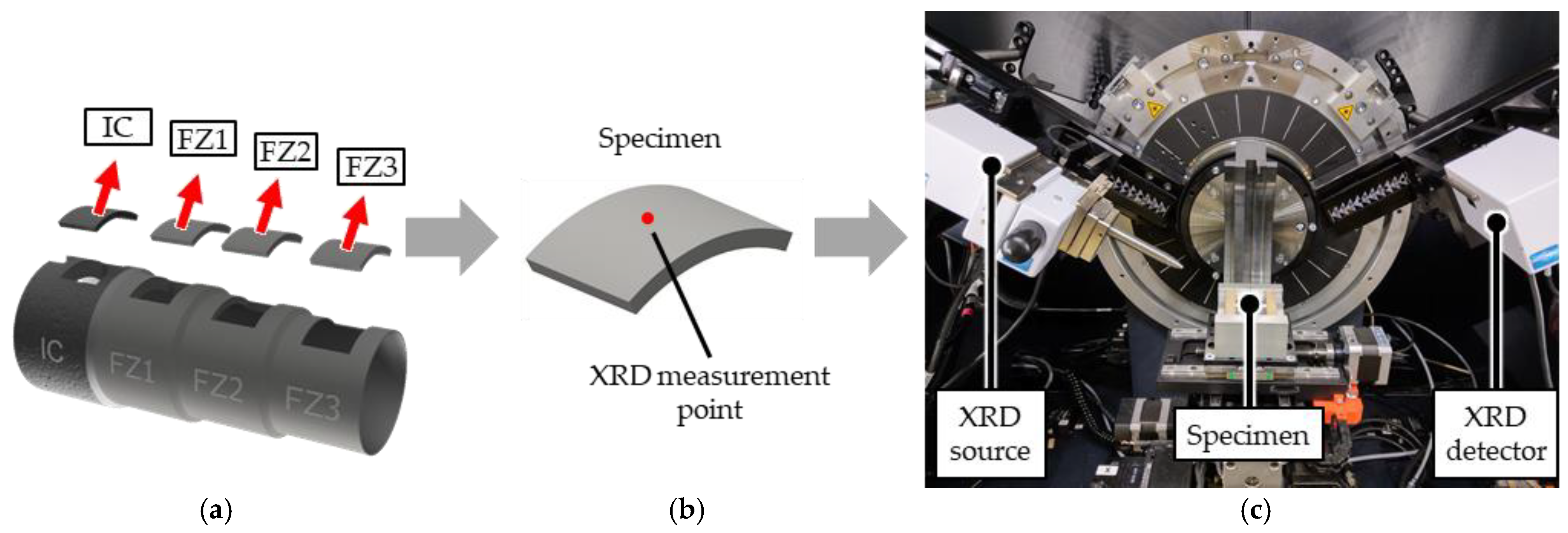
The specimens for the XRD analysis were extracted from flow formed tubes according to Figure 2a. The measurements were carried out on the outer surface of the specimens, as specified in Figure 2b. The X-ray diffractometer Bruker D8 Discover (Bruker Corp., Billerica, MA, USA) was used to perform the diffractometry analyses, the setup of which is specified in Figure 2c. According to the Bragg conditions, a change in lattice spacing induces a shift of the diffracted X-ray angle [24]. According to the crystal structure and space group of the present phases of the material, the intensity of the diffracted signals changes. Consequently, each phase produces a characteristic diffraction pattern. Additionally, when several phases are present in the material, the characteristic diffraction patterns of the phases are superimposed and the diffraction peaks of the phases are proportional to their amounts [16,25].
To perform phase analyses, diffraction patterns of the different material conditions were recorded. It is required that the diffraction pattern covers a large 2θ range to record as many peaks as possible. In this study, the measurements were performed on each specimen covering a 2θ range between 30 and 150° to detect the specific peaks for austenite or martensite. The measurements were carried out using a copper X-ray tube, with a 1 mm collimator, 40 mA current and 40 kV voltage.

2.2.2. Macro- and Microhardness Tests

To characterize the evolution of hardness during phase transformation, Vickers macro- and microhardness tests were performed. The indentations for the macrohardness tests were conducted on the outer surface of specimens at the initial condition (IC) and the forming zones 1 to 3 (FZ1, FZ2 and FZ3). The indentations for the microhardness mappings were conducted on cross sections of Specimen 1 at the IC, FZ1 and FZ3, as indicated in Figure 3.
The macrohardness tests were carried out on the device Wolpert Dia Testor 2 RC (Prueftechnik Buchmann GmbH & Co. KG, Michelfeld, Germany), using a load of 3 kgf. The microhardness measurements were performed using the HMV-G20 (Shimadzu Corp., Kyoto, Japan) tester. The indentations for microhardness were performed using a load of 0.05 kgf along the thickness of the specimens. Starting from the outer surface, the material was indented each 65 µm, on five lines, separated by ca. 200 µm from each other.

2.2.3. α′-Martensite Content

α′-martensite content measurements were carried out by means of the Feritscope FMP30 (Helmut Fischer GmbH, Sindelfingen, Germany). This device detects ferritic phase contents by means of the magneto-inductive method. Correlations developed by Talonen et al., 2004, allow for the computation of strain induced α′-martensite content from the ferritic phase measurements [19]. The measured α′-martensite content is used as a reference value for the martensitic phase amount.

2.2.4. Microstructural Characterization by Means of Scanning Electron Microscopy (SEM), including Electron Backscatter Diffraction (EBSD)

The microstructural characterization of the phase evolution was carried out by means of the SEM Tescan Mira 3 XMU (Tescan GmbH, Brno, Czech Republic). EBSD analysis was performed using the DigiView EBSD camera and the Team™ software, both manufactured by EDAX LLC (Pleasanton, CA, USA). The post-processing of results was conducted by means of the OIM analysis™ software (version 8.6.0028) also of EDAX LLC. The specimens were held with a specimen holder tilted at 70°, using an electron beam energy of 25 kV and a working distance ca. 20 mm.
Similar to the microhardness tests, the area of interest for the EBSD investigation corresponds with the cross sections of the initial condition (IC) and only the forming zones 1 and 3 (FZ1 and FZ3) of Specimen 1. The specimens were extracted from the flow formed tubes (Figure 3a) and underwent metallographic preparation. The EBSD investigation was carried out on cross sections, close to the outer surface of the tubes (Figure 3b). Phase and Inverse Pole Figure (IPF) mappings, 255 × 255 µm2 in size (Figure 3c), were measured for the analyses. Both kinds of mappings are presented superimposed on image quality (IQ) mappings. IQ in the background shows the quality of the diffraction patterns during the EBSD measurements which allows grain boundaries or areas with high degrees of deformation to become visible.

3. Results and Discussion

3.1. Microstructure Evolution by Means of Electron Backscatter Diffraction (EBSD)

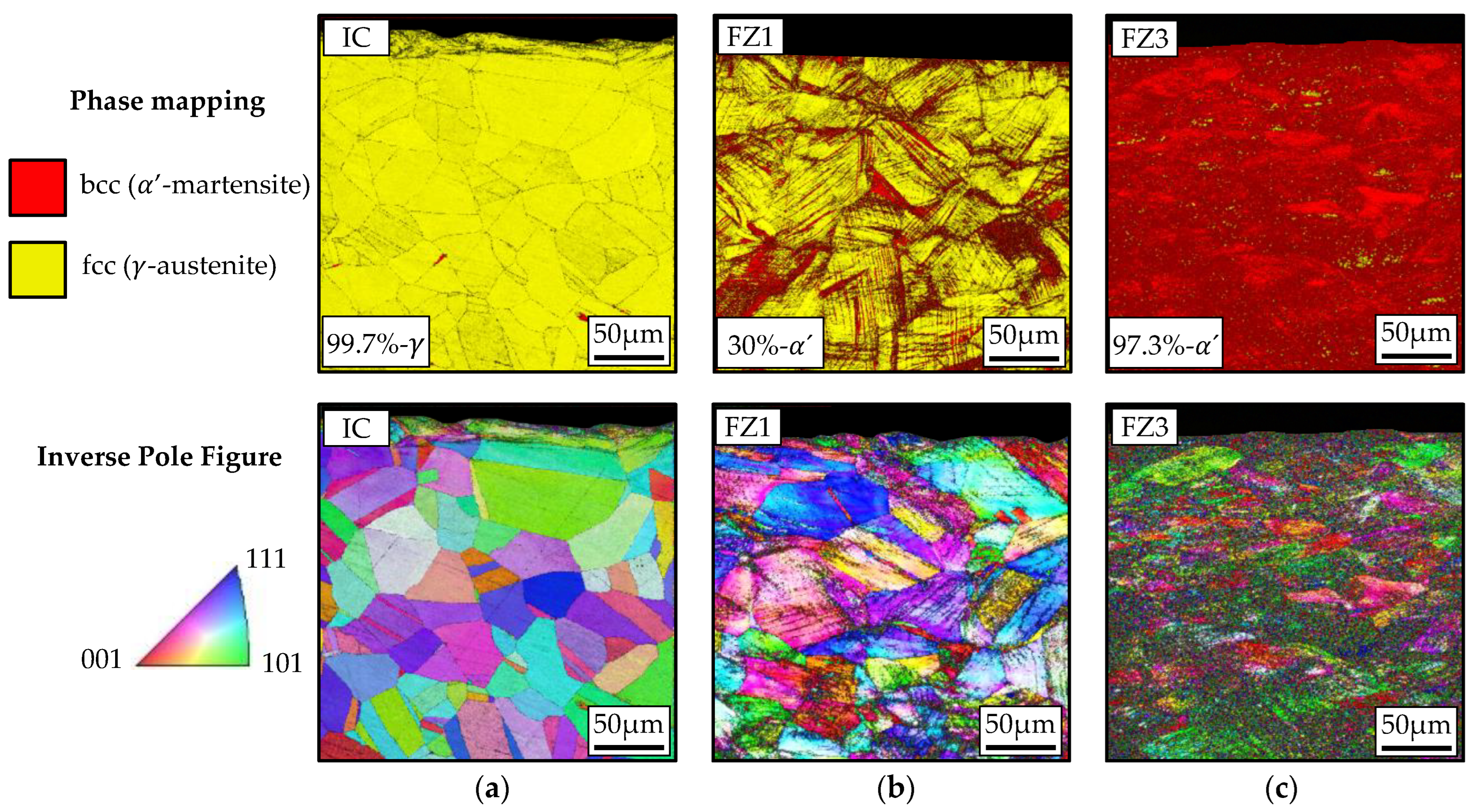
The results of the characterization of the microstructure evolution by means of EBSD are illustrated in Figure 4.
Using EBSD, a quantitative report of the amount of phase was carried out by means of the OIM analysis™ software. The phase analyses show that the microstructure at IC is dominantly γ -austenite (99.7%) with some ferromagnetic phases. The IPF map of the IC shows deformation-free grains with an average diametral size between 50 and 60 µm (Figure 4a). Due to plastic deformation, shear bands appear in FZ1, which is the typical deformation mechanism of metastable austenitic steels. The α ′-martensite nucleates at the intersection points of these shear bands, as was demonstrated and evidenced in [26]. The IPF map of FZ1 evidences the deformation-induced shear bands in a darker color, due to the IQ mapping on the background (Figure 4b). In FZ3, the microstructure is predominantly α ′-martensite (97.3%), with some austenite remaining. The IPF mapping of the FZ3 shows small typical martensite grains with a high amount of deformation (Figure 4c).

3.2. Microhardness Testing

In Figure 5, the microhardness mappings show the evolution of strain hardening in detail. Starting from the metastable austenite or initial condition (IC), an average hardness of 150 HV was recorded. This agrees with the reported hardness for AISI 304L steel on the data sheets. Close to the outer surface (upper side of the map in Figure 5a), the hardness is about 310 HV, likely due to the extrusion of the tubes used as raw material for flow forming. The mappings of the FZ1 and FZ3 evidence a higher Vickers hardness due to the strain hardening during plastic deformation. On FZ1, Vickers hardness measurements are between 400 and 480 HV (Figure 5b), and on FZ3, the hardness increases up to 520 HV (Figure 5c). Analyses of the cross sections of the specimens lead to the conclusion that hardness decreases gradually with the depth. For instance, at the outer surface of FZ3 the hardness reaches 520 HV and drops to 450 HV on the inner surface. However, the difference of the measurements at specific depths is not discussed in this paper, since the XRD analysis is limited to a few micrometers in depth.

3.3. Characterization of the Phase Transfromation by Means of XRD

As mentioned in Section 2.2.1, each phase produces a characteristic X-ray diffraction pattern. In this case, XRD methodology should be suitable to characterize the strain-induced transformation of the austenitic phase into the α′-martensite phase. To perform the phase analysis, the diffraction patterns were recorded covering a wide 2θ range. In this case, the measurements were performed between 30 and 150°.
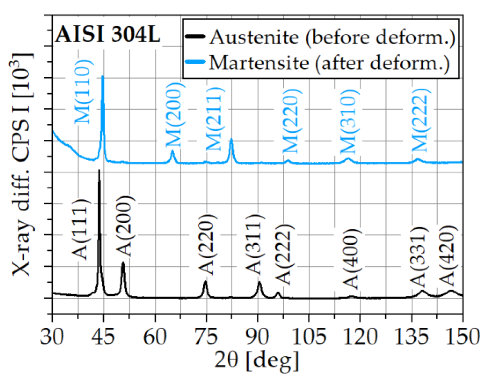
The measurements were conducted in four deformation conditions (IC and FZ1 to 3) of Specimens 1 and 2. Figure 6 shows two examples of the recorded diffraction patterns for specimens before deformation (metastable austenite) and after deformation with specific strain-induced α ’-martensite contents. Using a copper X-ray tube, diffraction peaks that represent specific (hkl) lattice planes are obtained at determined 2θ angles. This is summarized in Table 1 for austenitic and martensitic steels. The information in Table 1 agrees with the results in Figure 6, where the lattice planes corresponding to austenite (A) and martensite (M) are marked.
To perform detailed qualitative and quantitative phase analyses at different forming conditions by means of XRD, a high intensity peak at one specific 2θ angle must be selected. This peak must also be located in a 2θ position sufficiently separated from other austenite or martensite peaks to avoid an overlapping of the detected X-rays. Because of this, the peaks corresponding to A(111) at 2θ = 43.621° and M(110) at 2θ = 44.670° in Figure 6 are discarded despite having the maximum intensities. According to Figure 6, the peak with the next-highest intensity is at 2θ = 50.811°, which corresponds to the lattice plane A(200). A phase analysis on this plane is not possible, due to the poor signal of the deformed conditions (FZ1 to 3), as illustrated in Figure 7a for Specimen 1 and in Figure 7b for Specimen 2.
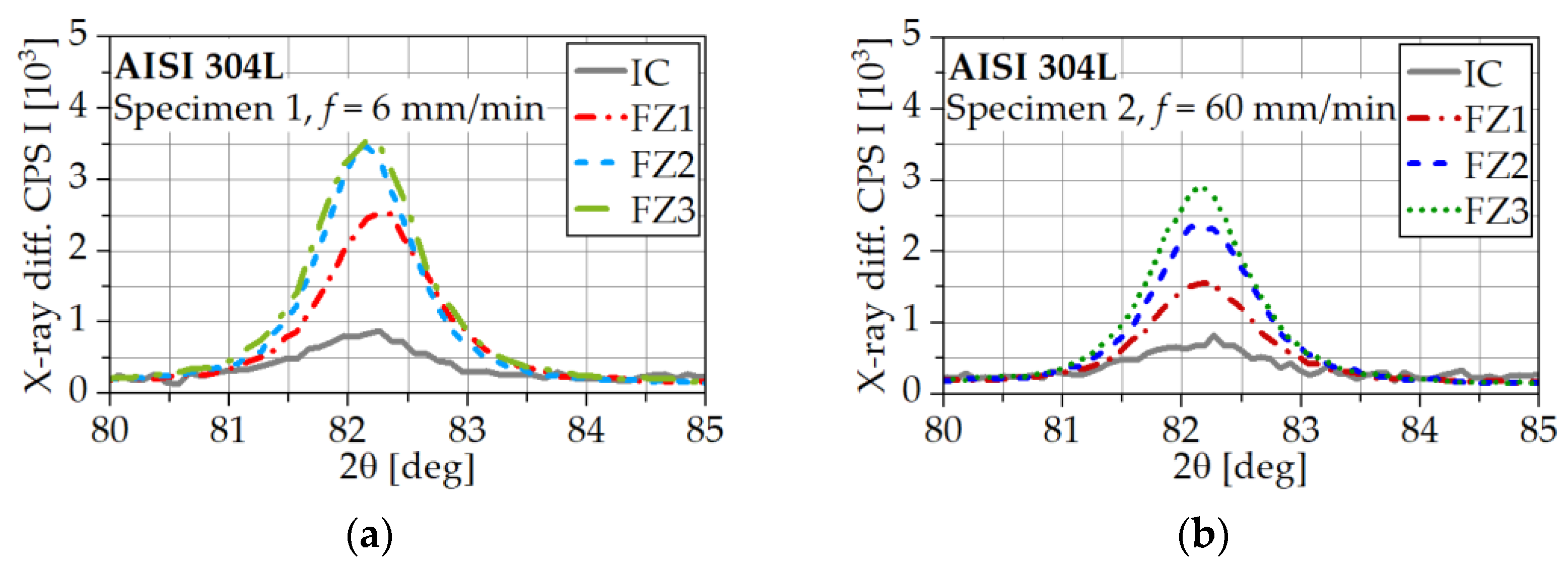
The next peak in Figure 6 with a remarkable intensity is the one at 2θ = 82.329°, which corresponds to the Miller index M(211) for martensitic steel, according to Table 1. Figure 8 shows details of the distribution of the diffraction peaks of the different forming conditions of both specimens. As expected, the measured peaks for IC on both specimens are around 0.8 × 10³ CPS, which is low in comparison with the peaks for the different FZs. The recorded signals of martensitic phases in IC are explained by the fact that the austenitic phase is not completely pure at IC, but does have some ferromagnetic phases, as shown in the pictures of Figure 4a.
The peaks of the further forming conditions show that the quantity of the martensitic phase increases with the deformation. In Specimen 1, a saturation of the measured peaks is reached in FZ2 and remains until FZ3 (Figure 8a). In Specimen 2, the measured XRD peaks also increase continuously with the deformation without reaching the saturation observed in Specimen 1 (Figure 8b). A comparison of the results in both specimens leads to the conclusion that the intensity of the peaks of Specimen 1 are higher than those of Specimen 2.

3.4. Correlations between XRD and α′-Martensite Contents

In this section a quantitative comparison of the XRD results with further characterization techniques was performed. To achieve this, measurements of α′-martensite with the Feritscope FMP30 (Helmut Fischer GmbH, Sindelfingen, Germany) were carried out. Table 2 summarizes the production parameters of the studied specimens, as well as the results of α′-martensite, macrohardness and XRD intensities in counts per second (CPS) of each deformation state. The reported XRD numerical values correspond to the peaks of each forming condition, measured at the martensitic lattice plane M(211) in Figure 8. The reasons for the selection of this lattice plane for the quantitative analysis of the mixture of austenite and martensitic phases were already discussed in Section 3.3.
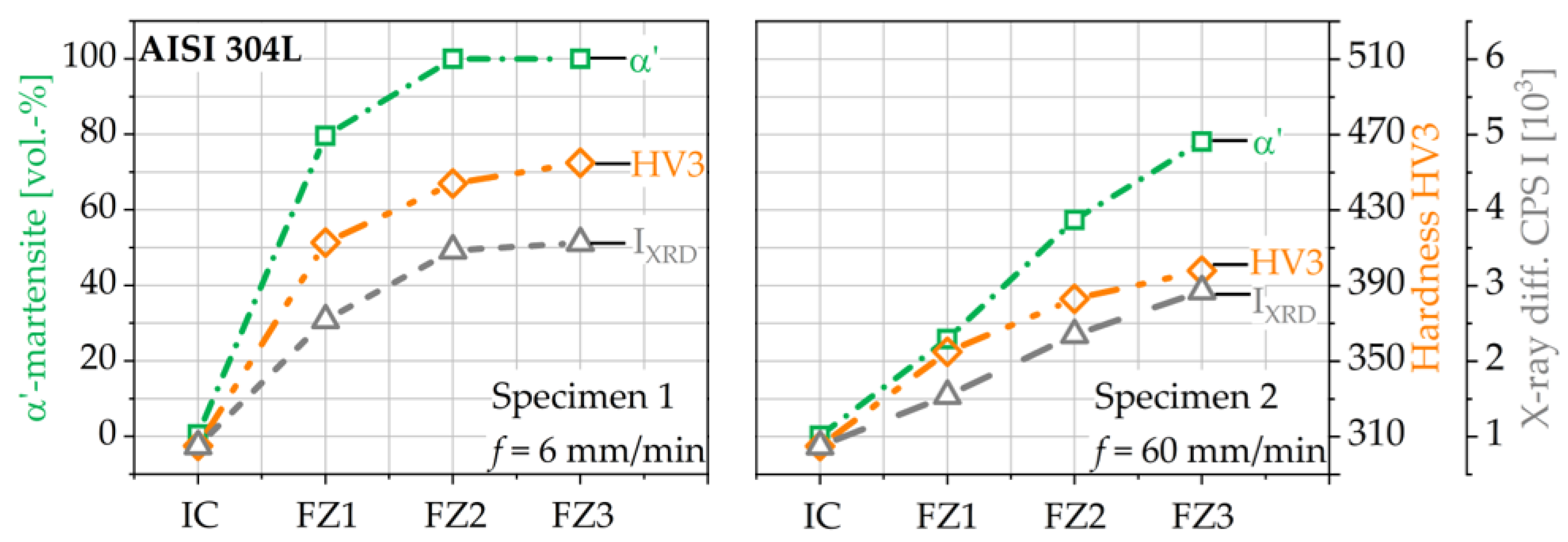
Figure 9 illustrates the results of Table 2 in correlation with the XRD measurements with α′-martensite amounts and the macrohardness measurements. The graphs display the strain hardening of the specimens due to the phase transformation from austenite to martensite. Martensite is well known as a very hard phase [27]. The higher the amount of α′-martensite, the harder the microstructure. The hardening of both specimens is proportional to the measured amount of α′-martensite. The quantitative results of the macro- and microhardness, shown in Figure 5, differ slightly from each other. While it is true that the microhardness measurements deliver reliable information on the local hardness distributions, it is a time-consuming and complex characterization technique. In contrast, macrohardness measurements can be carried out quickly, but the recorded information only illustrates the hardness in a global way. An indented point may correspond to a zone of higher or lower hardness since the distribution of properties after the forming process is not completely homogeneous.
The amount of α′-martensite in Specimen 1 increases from IC and reaches saturation (100%-α′) in FZ2. This was also evidenced by the measured XRD peaks and the EBSD micrographs in Figure 4c. A maximum XRD peak value of ca. 3.5 × 10³ CPS was recorded at FZ2 and there was no remarkable increment of it in FZ3. In Specimen 2, there is a quasilinear increment of the XRD with the deformation as well as the α′-martensite amount and hardness. In comparison, the amount of α′-martensite and XRD intensities are higher for Specimen 1 than 2, due to the lower feed rate used in the production of the former. The lower the feed rate of the tool during flow forming, the higher the local contact between the tool and the workpiece, thus producing a higher amount of plastic deformation, which favors the phase transformation. The microstructure of FZ1 is a mixture of austenite and martensite with the presence of shear bands, as illustrated in Figure 4b.
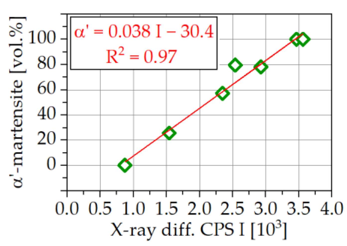
The collected data of the α′-martensite amount and XRD intensities were correlated by means of a linear approximation, as illustrated in Figure 10. With the utilized data, the coefficient of determination R2 is 0.97, which, in theory, is quite good. This is a first-model approach to performing quantitative phase analysis from XRD measurements. The number of measurements, however, is not large enough to estimate the validity of the correlation.

4. Conclusions

This investigation presents the results of a multi-technique characterization of phase transformation during the plastic deformation of metastable austenitic steel 304L. The focus was on the validation of the XRD method to characterize the amount of deformation in induced α′-martensite qualitatively and quantitatively. To achieve this, EBSD analyses of the microstructure evolution, the α′-martensite and the macro- and microhardness measurements were performed. The applied methodologies and final results demonstrate that the use of diffraction patterns obtained by means of XRD are suitable to characterize the phase transformation qualitatively. A quantitative analysis and the development of a model to calculate α′-martensite from the XRD intensity peaks was successfully conducted. A first linear approach was also proposed in the discussion, but to increase the reliability of the model, more data are required. A disadvantage of the XRD methodology is that the complete measurement of a diffraction pattern (~30° < 2θ < 150°) is complex and requires around 10 h/measurement. Once the peak of interest (in this case the peak M(211)) is identified, this time can be reduced. The goal of this investigation was not the formulation of a reliable model that uses the XRD measurements to compute the transformed phase amount. It was intended to present evidence of the capability of XRD for the detection of phase transformation, as a complementary method to validate other characterization techniques. By means of the methodologies used, the production parameters and the geometrical features of the workpieces were found to play an important role in the phase transformation process.
XRD was tested as a reliable characterization technique to evidence the phase transformation during the plastic deformation of metastable austenites. However, this technique is far from being used in applications that require a transmission of measurements in real time, e.g., closed-loop control systems. An alternative application of XRD analysis, apart from the well-known measurement of residual stresses, was successfully explored.

Author Contributions

Conceptualization and methodology J.R.V. and F.W; flow forming experiments and production of specimens B.A.; writing—original draft preparation, J.R.V., B.A. and L.K.; writing—review and editing, F.W., W.H. and A.T.; supervision F.W., W.H. and A.T.; funding acquisition F.W., W.H. and A.T. All authors have read and agreed to the published version of the manuscript.

Funding

Funded by the German Research Foundation (Deutsche Forschungsgemeinschaft, DFG)—project number 424335026—within the priority program SPP 2183 “Property-Controlled Forming Processes”. The authors thank the German Research Foundation and the Ministry of Culture and Science of North Rhine-Westphalia (Ministerium für Kultur und Wissenschaft des Landes Nordrhein-Westfalen, MKW RW) for their financial support within the major research instrumentation program for the “XRD-System”—project number 383863415.

Data Availability Statement

Not applicable.

Conflicts of Interest

The authors declare no conflict of interest.

References

  1. Marini, D.; Cunninigham, D.; Xirouchakis, P.; Corney, J. Flow forming: A review of research methodologies, prediction models and their applications. Int. J. Mech. Eng. 2016, 7, 285–315. [Google Scholar]
  2. Olson, G.B.; Cohen, M. Kinetics of strain-induced martensitic nucleation. Metall. Trans. A 1975, 6, 791–795. [Google Scholar] [CrossRef]
  3. Eigenmann, B.; Macherauch, E. Röntgenographische Untersuchung von Spannungszuständen in Werkstoffen. Teil III. Fortsetzung von Matwiss. und Werkstofftechn. Heft 3/1995, S. 148-160 und Heft 4/1995, S. 199-216. Mater. Werkst. 1996, 27, 426–437. [Google Scholar] [CrossRef]
  4. Eichhorn, F.; Zschau, M. Messung des Eigenspannungsabbaus durch Analyse des Barkhausen-Rauschens. Mater. Werkst. 1980, 11, 213–216. [Google Scholar] [CrossRef]
  5. Hauk, V. Structural and Residual Stress Analysis by Nondestructive Methods; Elsevier: Amsterdam, The Netherlands, 1997; ISBN 9780444824769. [Google Scholar]
  6. Fitzpatrick, M.E.; Fry, A.T.; Holdway, P.; Kandil, F.A.; Shackleton, J.; Suominen, L. Determination of Residual Stresses by X-ray Diffraction; Measurement Good Practice Guide No. 52; National Physical Laboratory: Teddington, UK, 2005; Available online: https://eprintspublications.npl.co.uk/2391/ (accessed on 12 March 2023).
  7. Strodick, S.; Vogel, F.; Tilger, M.; Denstorf, M.; Kipp, M.; Baak, N.; Kukui, D.; Biermann, D.; Barrientos, M.M.; Walther, F. Innovative X-ray diffraction and micromagnetic approaches for reliable residual stress assessment in deep rolled and microfinished AISI 4140 components. J. Mater. Res. Technol. 2022, 20, 2942–2959. [Google Scholar] [CrossRef]
  8. Simon, N.; Schell, N.; Gibmeier, J. On the oscillating course of dhkl−sin2ψ plots for plastically deformed, cold-rolled ferritic and duplex stainless steel sheets. Crystals 2023, 13, 419. [Google Scholar] [CrossRef]
  9. Muñoz, J.A.; Dolgach, E.; Tartalini, V.; Risso, P.; Avalos, M.; Bolmaro, R.; Cabrera, J.M. Microstructural heterogeneity and mechanical properties of a welded joint of an austenitic stainless steel. Metals 2023, 13, 245. [Google Scholar] [CrossRef]
  10. Manugula, V.L.; Lavanya, V.; Pardhu, Y. Microstructural characterization and hardness of an electron beam welded low carbon Ni-Cr-Mo low alloy steel. Mater. Today Proc. 2023. [Google Scholar] [CrossRef]
  11. Litovchenko, I.; Akkuzin, S.; Polekhina, N.; Almaeva, K.; Linnik, V.; Kim, A.; Moskvichev, E.; Chernov, V. The microstructure and tensile properties of new high-manganese low-activation austenitic steel. Metals 2022, 12, 2106. [Google Scholar] [CrossRef]
  12. Schulz, L.G. A direct method of determining preferred orientation of a flat reflection sample using a geiger counter X-ray spectrometer. J. Appl. Phys. 1949, 20, 1030–1033. [Google Scholar] [CrossRef]
  13. Bunge, H.J. Texture Analysis in Materials Science; Butterworth-Heinemann Ltd.: Oxford, UK, 1982; ISBN 9780408106429. [Google Scholar]
  14. Ahn, Y.-K.; Jeong, Y.-K.; Kim, T.-Y.; Cho, J.-U.; Hwang, N.-M. Texture evolution of non-oriented electrical steel analyzed by EBSD and in-situ XRD during the phase transformation from γ to α. Mater. Today Commun. 2020, 25, 101307. [Google Scholar] [CrossRef]
  15. Xu, W.; Zhang, J. Investigation of through-thickness residual stress, microstructure and texture in radial forged high-strength alloy steel tubes. Metals 2022, 12, 622. [Google Scholar] [CrossRef]
  16. Epp, J. X-ray diffraction (XRD) techniques for materials characterization. In Materials Characterization Using Nondestructive Evaluation (NDE) Methods; Hübschen, G., Altpeter, I., Tschuncky, R., Herrmann, H.-G., Eds.; Woodhead Publishing: Duxford, UK, 2016; pp. 81–124. ISBN 978-0-08-100057-1. [Google Scholar]
  17. Cheary, R.W.; Ma-Sorrell, Y. Quantitative phase analysis by X-ray diffraction of martensite and austenite in strongly oriented orthodontic stainless steel wires. J. Mater. Sci. 2000, 35, 1105–1113. [Google Scholar] [CrossRef]
  18. De, A.K.; Murdock, D.C.; Mataya, M.C.; Speer, J.G.; Matlock, D.K. Quantitative measurement of deformation-induced martensite in 304 stainless steel by X-ray diffraction. Scr. Mater. 2004, 50, 1445–1449. [Google Scholar] [CrossRef]
  19. Talonen, J.; Aspegren, P.; Hänninen, H. Comparison of different methods for measuring strain induced α-martensite content in austenitic steels. Mater. Sci. Technol. 2004, 20, 1506–1512. [Google Scholar] [CrossRef]
  20. Da Fonseca, D.P.M.; de Carvalho, L.G.; de Lima, N.B.; Padilha, A.F. Austenite formation in the oxidized layer of ultra-high-strength 13Ni15Co10Mo maraging steel. Metals 2022, 12, 2115. [Google Scholar] [CrossRef]
  21. Smaga, M.; Boemke, A.; Eifler, D.; Beck, T. Very high cycle fatigue behavior of austenitic stainless steels with different surface morphologies. Metals 2022, 12, 1877. [Google Scholar] [CrossRef]
  22. Zhang, S.Y.; Compagnon, E.; Godin, B.; Korsunsky, A.M. Investigation of martensite transformation in 316L stainless steel. Mater. Today Proc. 2015, 2, S251–S260. [Google Scholar] [CrossRef]
  23. Tomota, Y.; Sekido, N.; Harjo, S.; Kawasaki, T.; Gong, W.; Taniyama, A. In situ Observations of Transformation Behavior upon Heating for a 1.5Mn-1.5Si-0.2C Steel-Comparison between Neutron Diffraction, XRD, EBSD and Dilatometry-. ISIJ Int. 2017, 57, 2237–2244. [Google Scholar] [CrossRef]
  24. Spieß, L. Moderne Röntgenbeugung: Röntgendiffraktometrie für Materialwissenschaftler, Physiker und Chemiker, 2nd ed.; Vieweg + Teubner Verlag: Wiesbaden, Germany, 2009; ISBN 978-3-8351-0166-1. [Google Scholar]
  25. Cullity, B.D.; Stock, S.R. Elements of X-ray Diffraction, 3rd ed.; Prentice Hall: Upper Saddle River, NJ, USA, 2001; ISBN 9780201610918. [Google Scholar]
  26. Rozo Vasquez, J.; Kanagarajah, H.; Arian, B.; Kersting, L.; Homberg, W.; Trächtler, A.; Walther, F. Coupled microscopic and micromagnetic depth-specific analysis of plastic deformation and phase transformation of metastable austenitic steel AISI 304L by flow forming. Pract. Metallogr. 2022, 59, 660–675. [Google Scholar] [CrossRef]
  27. Mangonon, P.L.; Thomas, G. The martensite phases in 304 stainless steel. Metall. Trans. 1970, 1, 1577–1586. [Google Scholar] [CrossRef]
Figure 1. Specimen manufacture: (a) flow forming process; (b) flow forming machine; (c) geometry and dimensions (in mm); (d) final workpieces. IC: Initial condition, forming zones (FZ) 1–3.
Metals 13 01007 g001
Figure 2. Specimen preparation for XRD analyses: (a) extraction of specimens from the tubes; (b) geometry of the specimens; (c) setup of the X-ray diffractor.
Metals 13 01007 g002
Figure 3. Specimen for microscopic investigation of the microstructure evolution: (a) extraction of specimens from the tubes; (b) cross section of the specimens; (c) mapping size of the EBSD analysis.
Metals 13 01007 g003
Figure 4. Microstructure evolution measured with electron backscatter diffraction (EBSD) by means of phase analysis and IPF mappings of (a) metastable austenite, initial condition (IC); (b) deformation-induced martensite, forming zone 1 (FZ1); (c) forming zone 3 (FZ3).
Metals 13 01007 g004
Figure 5. Microhardness mappings of (a) metastable austenite, initial condition (IC); (b) deformation-induced martensite, forming zone 1 (FZ1); (c) forming zone 3 (FZ3).
Metals 13 01007 g005
Figure 6. Diffraction pattern of a metastable austenitic steel AISI 304L before (black) and after (blue) plastic deformation.
Metals 13 01007 g006
Figure 7. XRD peaks of AISI 304L at plane (hkl) = (200) for two specimens at different deformation states: (a) Specimen 1; (b) Specimen 2.
Metals 13 01007 g007
Figure 8. XRD peaks of AISI 304L at lattice plane (hkl) = (211) for two specimens at different deformation states: (a) Specimen 1; (b) Specimen 2.
Metals 13 01007 g008
Figure 9. Correlation between α′-martensite content, macrohardness and XRD peak intensity in counts per second (measured at lattice plane (hkl) = (211)) for two specimens of AISI 304L at different forming conditions.
Metals 13 01007 g009
Figure 10. Linear regression between α′-martensite content and X-ray diffraction intensity for metastable austenitic steel AISI 304L.
Metals 13 01007 g010
Table 1. Data for XRD analyses using a Cu Kα1 X-ray tube in austenitic and martensitic steels (extracted from [3]).
MaterialPlane
(hkl)
E(hkl)
[103 N/mm3]
υ(hkl)
[deg]
MaterialPlane
(hkl)
E(hkl)
[103 N/mm3]
υ(hkl)
[deg]
Austenitic
steel
A(420)
A(331)
A(400)
A(222)
A(311)
A(220)
A(200)
A(111)
176
217
139
247
175
207
139
247
0.31
0.27
0.35
0.24
0.31
0.28
0.35
0.24
147.2
138.464
118.194
95.989
90.705
74.706
50.811
43.621
Martensitic
steel
M(222)
M(310)
M(220)
M(211)
M(200)
M(110)
248
181
220
220
165
220
0.25
0.32
0.28
0.28
0.33
0.28
137.141
116.372
98.937
82.329
65.019
44.670
Table 2. Quantitative measurements of α′-martensite and XRD peak intensities (measured at lattice plane (hkl) = (211)) for two specimens of AISI 304L under different forming conditions.
SpecimenIdeal Thickness
[mm]
Feed Rate
[mm/min]
α′-Martensite
[vol.%]
Macrohardness
HV3
XRD CPS I
[103]
Specimen 1:
IC4 0.543050.872
FZ13 79.65412.62.54
FZ2261004443.464
FZ31 1004453.563
Specimen 2:
IC4 0.23050.83
FZ13 25.83551.543
FZ226057.453832.347
FZ31 78.143982.928
Disclaimer/Publisher’s Note: The statements, opinions and data contained in all publications are solely those of the individual author(s) and contributor(s) and not of MDPI and/or the editor(s). MDPI and/or the editor(s) disclaim responsibility for any injury to people or property resulting from any ideas, methods, instructions or products referred to in the content.