Article

Effect of Brazing Temperature on Microstructure, Tensile Strength, and Oxide Film-Breaking Synergy of 5A06 Aluminum Alloy Welded by TG-TLP

1
School of Aeronautical Manufacturing Engineering, Nanchang Hangkong University, Nanchang 330000, China
2
Shanghai Aerospace Equipments Manufacturer Co,. Ltd., Shanghai 200245, China
3
State Key Laboratory of Advanced Welding and Connection, Harbin Institute of Technology, Harbin 150001, China
4
Hefei Institutes of Physical Science, Chinese Academy of Sciences, Hefei 230000, China
*
Authors to whom correspondence should be addressed.
Metals 2023, 13(6), 1048; https://doi.org/10.3390/met13061048
Submission received: 23 April 2023 / Revised: 17 May 2023 / Accepted: 22 May 2023 / Published: 30 May 2023
(This article belongs to the Special Issue Advanced Metal Welding and Joining Technologies)

Abstract

:
5A06 aluminum alloy bar was brazed by temperature gradient transient liquid phase diffusion welding (TG-TLP). The effects of brazing temperature on the microstructure and the tensile strength of the brazing joints were investigated. Three typical brazing filler alloys (1# Al-20Cu-6Si-2Ni, 2# Al-10Cu-10Si-3Mg-1Ga, and 3# Al-6Cu-10Si-2Mg-10Zn) were prepared by smelting, and TG-TLP diffusion bonding was carried out at different brazing temperatures (550 °C~590 °C). The results show that with the increase in brazing temperature, the oxide films at the brazing junction are easier to be broken and dispersed, but the oxidation extent will also increase. The oxidation products enriched were mainly Al2O3 and SiO2 at the brazing junction. There are different optimal brazing temperatures corresponding to the different filler alloys. For 1#, the optimal temperature is 570 °C; for 2# is 580 °C; for 3# is 580 °C. For 1# brazing joints, the maximum tensile strength was 113 MPa, and for 2# was 122.4 MPa. Under the experimental conditions of this study, the maximum tensile strength of the TG-TLP joint is 147.4 MPa of 3# brazing sample (at 580 °C), which has increased by 30% and 20% compared to 1# and 2# respectively. The nickel-rich phase at the interface (of 1# brazing filler) could form a brittle fracture, which was unfavorable for interface bonding. For TG-TLP brazing of 5A06, the filler alloy with high Al:Cu ratio (12:1 wt.%) needs a sufficient temperature gradient to exert the film-breaking effect, while the filler alloy with low Al:Cu ratio (3.6:1 wt.%) needs to accurately control its brazing temperature to avoid excessive oxidation. There are many research gaps in the influence of brazing material composition and brazing temperature on the microstructure and mechanical properties of 5A06 aluminum alloy TG-TLP joints. The research results can provide a theoretical basis for formulating the TG-TLP brazing specification of 5A06 aluminum alloy.

1. Introduction

The 5A06 aluminum alloy is a type of non-heat-treatment Al-Mg alloy with high specific strength, excellent corrosion resistance, and good weldability. It is widely used in aerospace, shipbuilding, pressure vessel, and other fields, especially in alloy conduit components [1]. It’s important to note that aluminum alloy conduits and bar materials play a critical role in spacecraft manufacturing, including carrier rockets, manned spacecraft, and space stations. The connection of these materials is crucial for ensuring the safe operation of spacecraft [2,3,4]. However, the current method of manufacturing these conduits, tungsten argon arc welding (TIG), could have defects such as pores, unstable quality, and low qualified rate [5]. This presents a challenge for spacecraft manufacturing enterprises to find efficient and reliable ways to connect aluminum alloy conduits.
The principle of transient liquid phase diffusion welding (TLP) is to achieve welding by placing a special composition interlayer between the work pieces to be welded, heating it above the melting temperature of the middle layer, while applying a certain pressure, and holding it for a certain time after this interlayer melts, so that the elements between it and the base material diffuse sufficiently to allow isothermal solidification to occur and finally achieve welding [6,7,8]. For the brazing of dissimilar materials, the interfacial compound phase (oxide or intermetallic compound) of the joint is the key factor affecting the strength [9,10]. TLP pipe welding process is an advanced welding method with high efficiency, high quality and low distortion [11]. However, due to the strong oxidation of aluminum alloy in the atmospheric environment, a layer of stable oxide film will form on the entire surface in 1.7 × 10⁻⁸ S. The oxide layer is difficult to remove in the process of the TLP diffusion welding, which is the main reason to hinder the application of the TLP welding process in aluminum alloy connection [12].
Aluminum alloy TLP bonding in a vacuum environment is effective in reducing joint oxide generation, but its practical application is limited by the vacuum equipment and workpiece size. The study of non-vacuum TLP connections for aluminum alloys is of great importance for practical production. There are two main solutions to the problem of non-vacuum TLP bonding oxide film on aluminum alloys. One is ultrasonic assisted welding, using ultrasonic vibration to break the oxide film on the surface of aluminum alloy. Guo [13] performed ultrasound-assisted TLP bonding on 7034 high-strength aluminum alloy and found that the oxide film could be effectively broken by ultrasonic vibration, which also had a facilitating effect on element diffusion and shortened isothermal solidification time. Similarly, Qiang [14] used ultrasound assistance to achieve high-strength TLP bonding of 6061 aluminum alloy in air. However, the introduction of ultrasonic equipment makes the welding process complex and the operation more cumbersome. Another method is the temperature gradient TLP diffusion welding (TG-TLP) proposed by Assadi [15], whose principle is to apply a temperature gradient in the transverse direction of the joint, which can transform the weld interface from a flat interface in conventional TLP to a sinusoidal, honeycomb or even dendritic interface. Jabbareh [16] investigated the formation of wavy bond lines in TLP bonding using a multigrain phase field model, and the results showed that unidirectional interfacial migration can be achieved at temperature gradients. According to the welding theory, the temperature gradient TLP connection can not only break the oxide film on the surface of the base metal, but also increase the contact with the base metal due to the extension of the sinusoidal or cellular interface, which is conducive to the improvement of the strength of the brazing joint. At present, the research on TG-TLP brazing of 5A06 and other series aluminum alloys was still relatively limited, and the actual effect of interface film-breaking theory needs to be further verified.
As there was no TLP welding specification for 5A06 aluminum alloy, the selection of filler metal composition refers to the existing research in this study. Al-Cu-Si-Ni [17] is one of the typical brazing filler metal systems applied to the aluminum alloys, belonging to the Al-Cu-Si system. Cu and Si are used as melting point depressants (MPD) [18]. Ni is used to replace the part of Cu to reduce the formation of Al2Cu brittle intermetallic compounds while maintaining good mechanical properties and corrosion resistance of the joint. The other filler metal system is Al-Cu-Si-Mg(-Ga) [19,20]. On the basis of adding Mg as the film-breaking element, an appropriate amount of Ga is added to assist [21]. In addition, there is an Al-Cu-Si-Mg-Zn system [22,23]. Si exists as the main reducing melting element, and its content is selected to be near the Al-Si eutectic point. Mg can reduce Al2O3 to break the oxide film [24]. Excessive Mg and Si can form brittle-phase Mg2Si, so its content needs to be controlled. The element of Zn has a high solubility in Al, and its diffusion speed is fast. At the same time, the melting point of Zn is low, which is beneficial to reduce the liquidus temperature of the intermediate layer.
There is a demand for the application of 5A06 material and its connectors in spacecraft pipelines, but considerable research gaps exist in the corresponding TG-TLP welding process and the brazing filler alloy design. The microstructure, phase distribution, as well as the effect of the TLP method on the interfacial oxide layer of the TG-TLP aluminum alloy welded joints, are also the focus of this study, which lacks reference. In this study, the TG-TLP welding of 5A06 aluminum alloy was carried out according to the existing brazing process and the typical filler alloy composition. The effect of brazing temperature (temperature gradient) on the properties of non-vacuum TG-TLP diffusion brazing joints was studied, and the mechanism of oxide film-breaking was explored.

2. Materials and Methods

The base metal for TLP welding is a 5A06 aluminum alloy bar (MELAL Metal Materials Co., Ltd., Suzhou, China), with a diameter of 20 mm and a length of 180 mm. 5A06 is Al-Mg anti-rust aluminum, and its elemental composition is shown in Table 1. Al-Cu-Si alloy was selected as the brazing filler metal (or interlayer layer metal) with a thickness of 0.2 mm. In this study, considering the effects of various elements, three kinds of interlayer components were designed and prepared: 1# Al-20Cu-6Si-2Ni, 2# Al-10Cu-10Si-3Mg-1Ga, and 3# Al-6Cu-10Si-2Mg-10Zn. Microwave heating furnace (Microwave Muffle Furnace, SWX, MOBILELAB-T, Tangshan, China) was selected for smelting equipment. As shown in Figure 1, the initial as-cast brazing filler alloy was a bar, and finally it was wire cut into a slice with the dimension of Φ 22 mm × 0.1 mm. Before brazing, the samples were pretreated by combining with the physical removal of the oxide film and the chemical cleaning: after grinding with a wire brush, the sample was put into 100 g/L NaOH aqueous solution, washed with alkali at 40–60 °C for 1–3 min, and then put into 15% HNO3. Wash the material again with absolute ethanol to remove impurities in an aqueous solution.
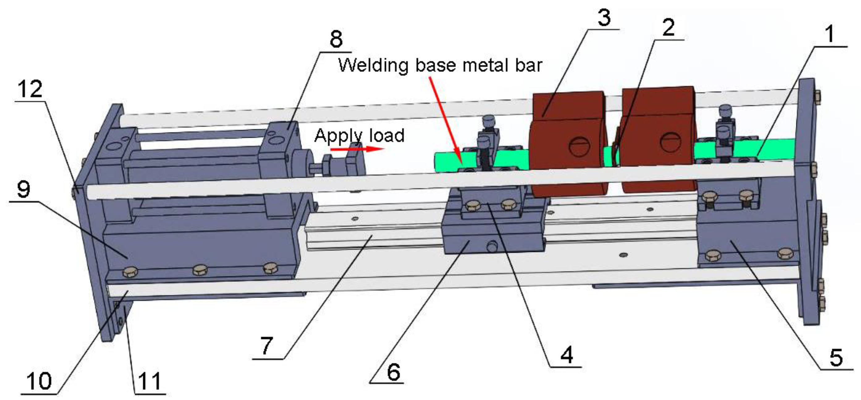
The brazing equipment used was the high-frequency induction heating device (SP-45AB, Shuangping Power Technology, Shenzhen, China). The maximum input power is 45 kW, and the oscillation frequency is 30–80 kHz. The brazing fixture was self-designed, and its structure and components are detailed in Figure 2. Before brazing, the two base metal bars were clamped on both sides of the fixture and the brazing filler alloy was placed between them. The axial load was applied through the cylinder push rod. The brazing area was adjusted into the induction coil by moving the guide rail. During the brazing, water-cooled copper rings were used to cool the base metal and realize the temperature gradient (TG). Ar gas was used for local protection during the brazing process.
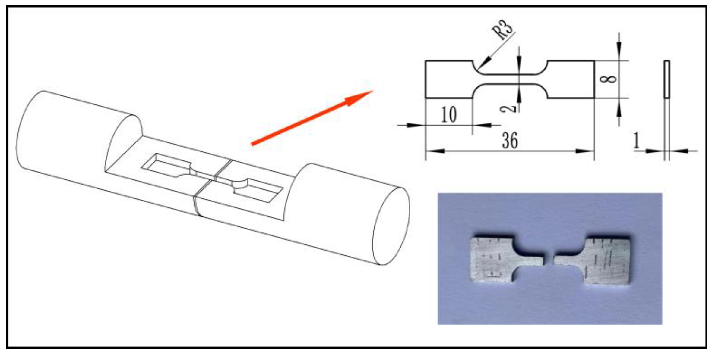
Corresponding to the 1#, 2#, and 3# brazing filler alloys, the liquidus temperatures are 541.32, 550.00, and 561.66 °C, respectively (by the theoretical calculation used JMatPro V7.0 software). The choice of brazing parameters is the key to obtaining high-quality welded joints. The liquid phase line temperatures of the three brazing filler materials used in this paper were in the range of 540 °C to 560 °C. To ensure that the interlayer is fully melted during the brazing process, the joint temperatures were set to be 10 °C higher than the liquid phase line. To avoid the joint softening caused by excessive brazing temperature, the upper temperature limit was set to 30 °C above the liquid phase line. At the same time, the brazing temperature is the main factor affecting the diffusion of elements, the higher the temperature, the faster the diffusion of elements, which is conducive to isothermal solidification and homogenization of the composition of the brazing process. However, too high a temperature has a negative impact on the properties of the base material and can lead to the phenomenon of localized coarsening of the base material under pressure. The TLP joint holding time should be selected to ensure sufficient time to complete isothermal solidification of the joint tissue so that the local brittle eutectic phase does not degrade the joint performance. Wang et al. [25] showed that when the holding time of 30 min can be obtained when the performance of welded joints. In addition, the lower pressure ensures the quality of the weld while promoting the diffusion of the elements. The number and the brazing parameters of the series of samples are shown in Table 2. Brazing temperature was 550~590 °C; the holding time was 30 min; the applied load was 0.1 MPa; the distance between the water-cooled copper rings and the weld joint was 40 mm. The tensile specimens were prepared by an electric spark-cutting machine. Figure 3 shows the sampling location and the size of the specimen which referenced the standard of CNHB-5145-1996. A universal tensile testing machine (WDW-100, Yanrui Test Instrument, Jinan, China) was used for the tensile strength test, with a maximum tensile force of 100 kN and a tensile speed of 0.5 mm/min. 3 samples were used for each group of tensile strength results and the average was taken. The microstructures of the welded joints were observed by the scanning electron microscope (SEM, Phenom XL, Phenom, Eindhoven, The Netherlands). The material composition analysis was carried out by the energy dispersive spectroscopy detector (EDS, FAST SDD, Ametek, Brooklyn Park, MN, USA) attached to the electron microscope.

3. Results and Discussion

3.1. Effect of BrazingTtemperature on the Microstructures of TG-TLP Joints

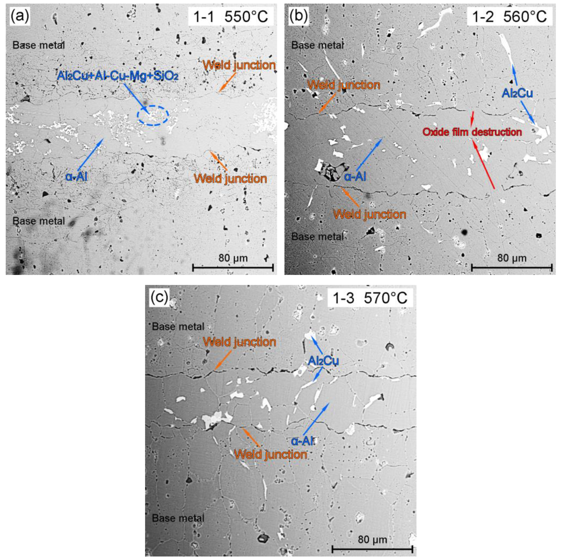
Figure 4a–c shows the SEM microstructures of the brazing joints of Al-6Cu-10Si-2Mg-10Zn (1#) brazing filler alloy at different brazing temperatures (550~570 °C). With the increase of the brazing temperature, the phase transformation of the filler metal occurs at the weld joint. According to Figure 4a, under the brazing temperature of 550 °C, the phases of weld joints is “α-Al + flocculent mixed phase”, in which the mixed phase is composed of Ni-rich Al2Cu + Al-Cu-Mg + SiO2. Al2Cu and SiO2 were confirmed by EDS. Due to the low content of Al-Cu-Mg, the XRD (X-Ray Diffraction) results did not distinguish the peaks of this phase. Based on the EDS results, morphology observation results in Figure 5, and the references [26,27,28], it is determined that its possible phase was AlCuMg eutectic. As shown in Figure 4b, under 560 °C, the flocculent mixed phase gradually disappeared, and Al2Cu became the main secondary phase (with a small amount of Al-Cu-Mg). With the increase of the temperature, the internal diffusion of the alloy was strengthened, and the Al2Cu phase is also precipitated in the base metal. As shown in Figure 4c, when the brazing temperature increased to 570 °C, the phase composition is the same as that at 560 °C (α-Al main phase + Al2Cu second phase). At 570 °C, the grain size in the weld joint was significantly larger than that at other temperatures. The content of oxides (as Figure 6 for composition analysis) also has a marked increase, especially at the weld junction.
Compared with Figure 4a–c, the weld junction was more obvious at the brazing temperature of 550 °C and 570 °C, while the weld junctions partially disappeared at the brazing temperature of 560 °C. The darker areas (or lines) of the weld junctions corresponded to the higher oxygen contents, that is, there were thin films formed by oxides enrichment. At the lower brazing temperature (550 °C), there were fewer oxides formed, but the driving force of film (oxide film) breaking corresponding to TG-TLP welding theory was insufficient; At the higher brazing temperature (570 °C), the driving force of film-breaking increased, but the oxides also increased. Both of the above conditions were not conducive to the reduction of oxide films. It could be seen from the most obvious film-breaking effect at 560 °C that an appropriate brazing temperature was needed to obtain a reasonable temperature gradient, to balance the film-breaking effect and the oxide formation.
Figure 5a–g shows the typical phase composition and the element mapping analysis results of the flocculent mixed phase (in Figure 4a). As shown in Figure 5a, for Al-20Cu-6Si-2Ni brazing filler alloy, the alloy phase at the brazing joint included the main phase α-Al, the Al-Cu-Mg, the Al2Cu, and the SiO2. Al-Cu-Mg was reticulated and distributed at the grain boundary; Al2Cu and SiO2 were distributed in the α-Al which is near the grain boundary. As shown in Figure 5e, the Ni element of the brazing filler was mainly enriched in the Al2Cu phase. Mg element formed segregation in some of the SiO2 phases.
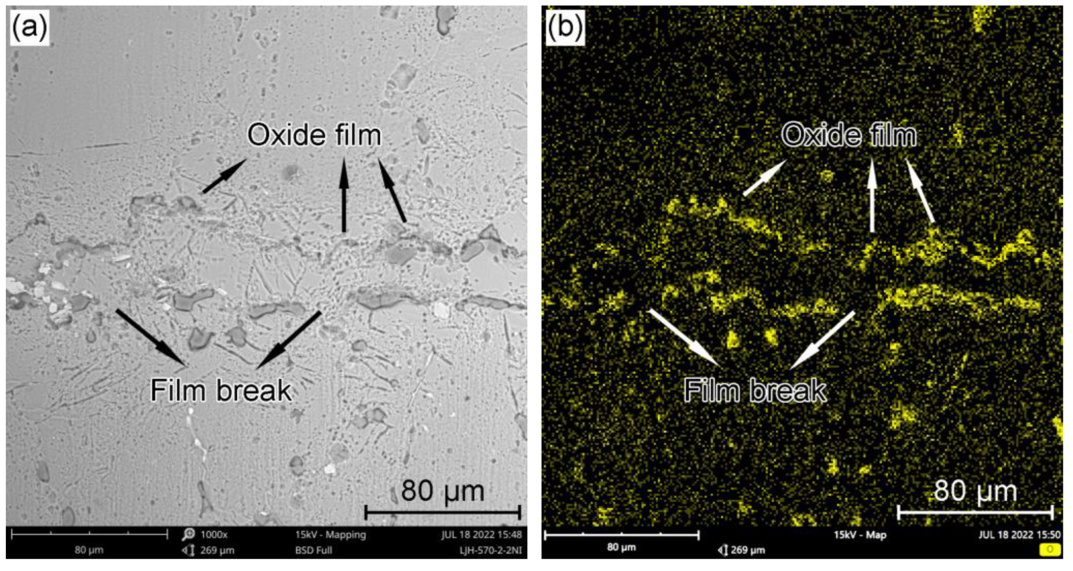
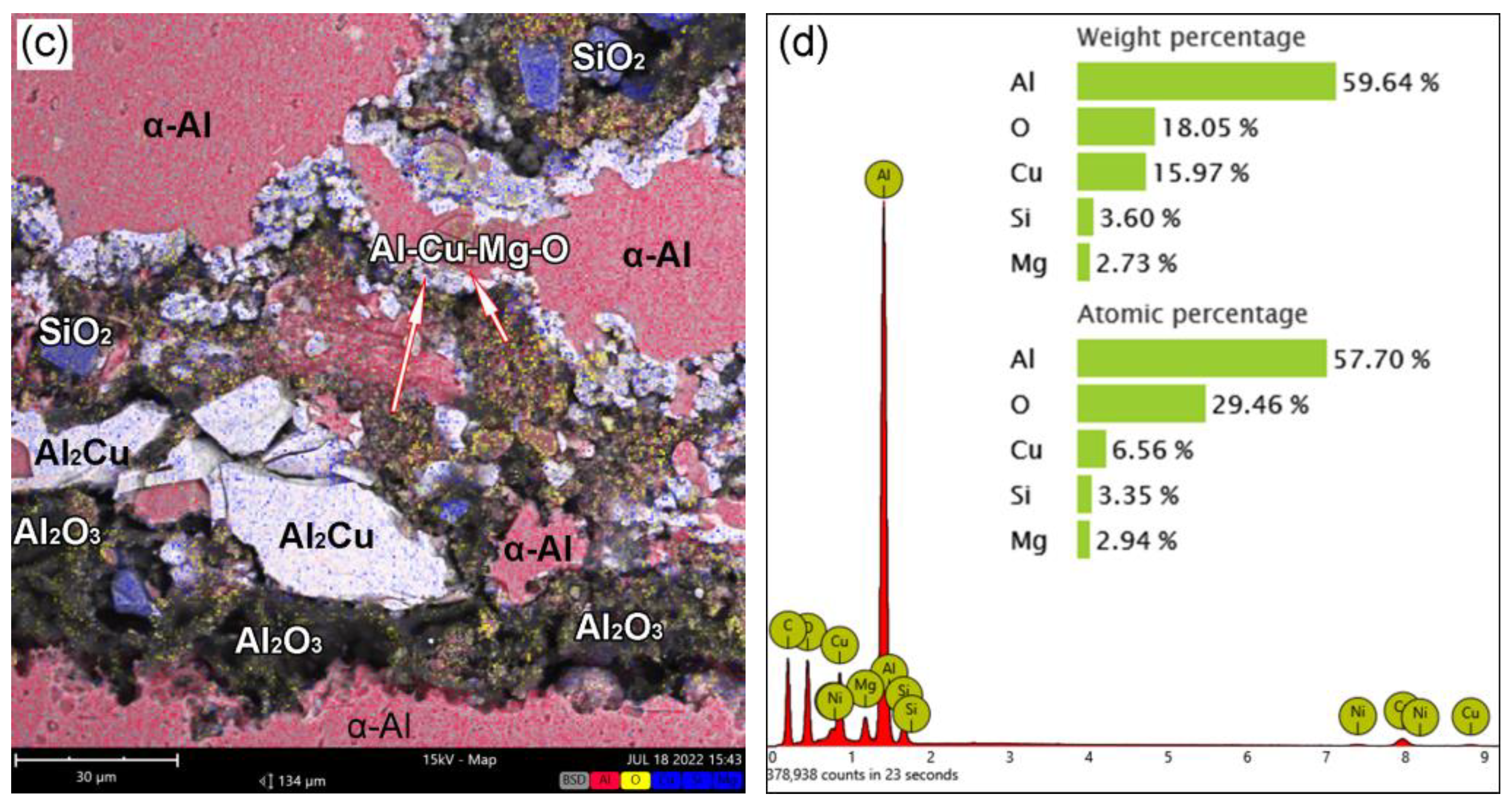
Figure 6a shows the typical oxide (film) distribution at the weld junction. It can be observed from the mapping analysis of the O element (Figure 6b) that the oxide film at the weld junction had been broken. With the increase in the brazing temperature, oxidation intensified, and the thickness of the oxidation film would also increase. Figure 6c shows the morphology and composition of the oxide film with local magnification. The oxide film is mainly composed of Al2O3, SiO2, and oxides containing Al, Cu, and Mg elements (possible eutectic oxides). According to the element quantitative analysis results in Figure 6d, the oxygen content in the oxide film area had reached 18 wt.%. In this study, for 1# brazing filler, under TG-TLP welding mode, the film-breaking effect with 560 °C brazing temperature is the best.
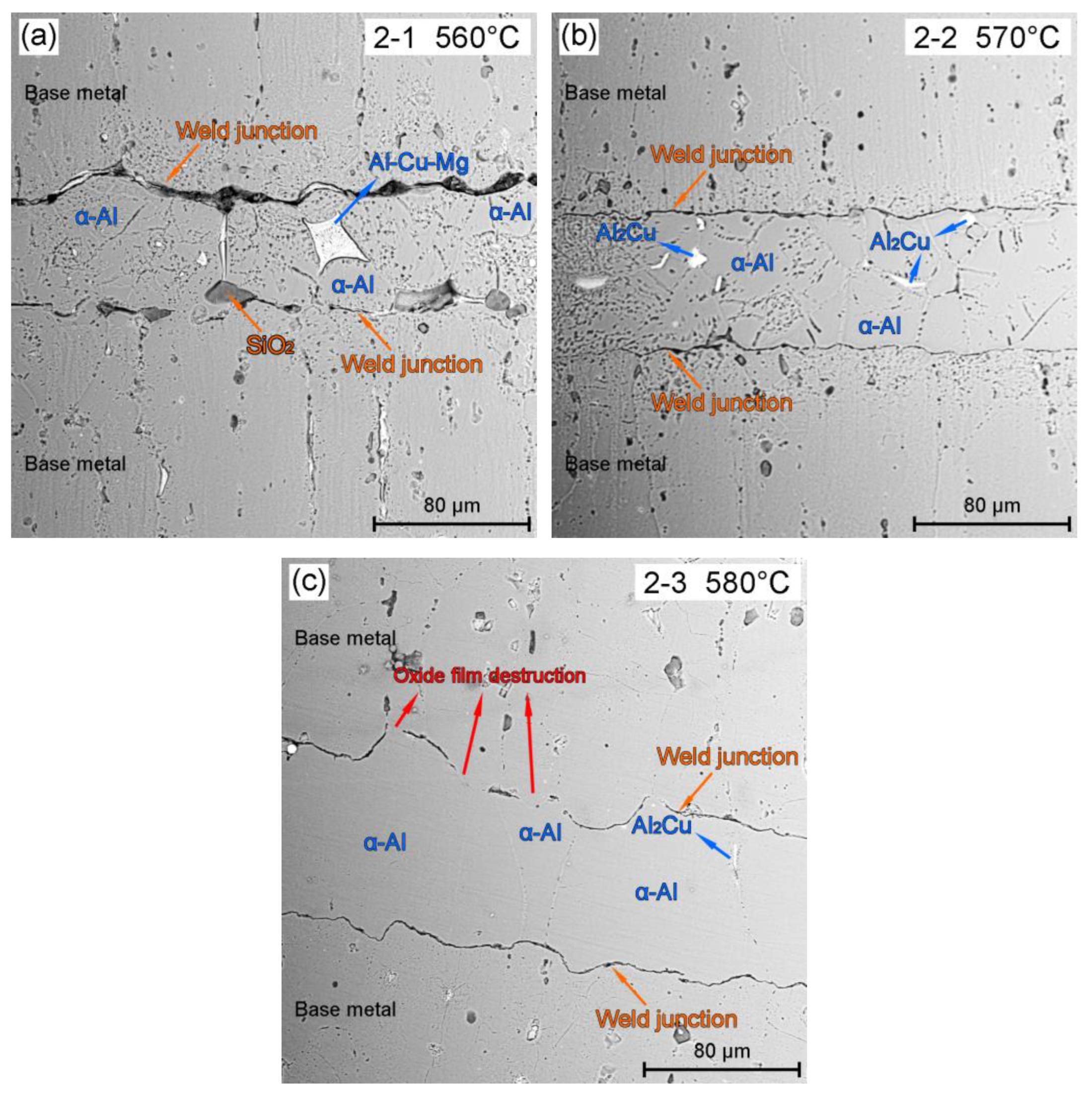
Figure 7a–c shows the SEM microstructures of the brazing joints of Al-10Cu-10Si-3Mg-1Ga (2#) brazing filler alloy at different brazing temperatures (560~580 °C). With the change in the brazing temperature, there was an obvious phase transformation at the weld joint. According to Figure 7a, under the brazing temperature of 560 °C, the phases of weld joints are the α-Al main phase and the Al-Cu-Mg. At this brazing temperature, the oxidation at the weld joint was relatively serious, and the SiO2 phase (confirmed by EDS) was enriched here. As shown in Figure 7b, as the brazing temperature rose to 570 °C, the Al-Cu-Mg phase disappeared and the second phase at the brazing joint changed to Al2Cu. The oxides including SiO2 at the weld junction were reduced. Unlike 1# brazing filler, 2# brazing filler had higher oxide contents at the lower temperature. This phenomenon was still related to the combined effect between the oxide film-breaking mechanism of TG-TLP and the high-temperature oxidation. Because the 2# brazing filler with higher Al content (lower Cu content) was easier to oxidize at all brazing temperatures and could produce more oxides (mainly Al2O3) at lower temperatures (560 °C). When the temperature rose to a certain degree, the film-breaking and wetting cleaning mechanism of TG-TLP could play its role and reduce the oxidation products to a certain extent. As shown in Figure 7c, the SEM observation results at 580 °C were consistent with this rule, and the oxide films were obviously broken. Due to the further increase in the temperature, the Al2Cu phase basically disappeared, and the brazing joint microstructure was a uniform α-Al phase, which was beneficial to the improvement of the weld joint strength. It can be predicted that the oxides will still increase when the brazing temperature continues to rise. For 2# brazing filler, under TG-TLP welding mode, the film-breaking effect with 580 °C brazing temperature is the best.
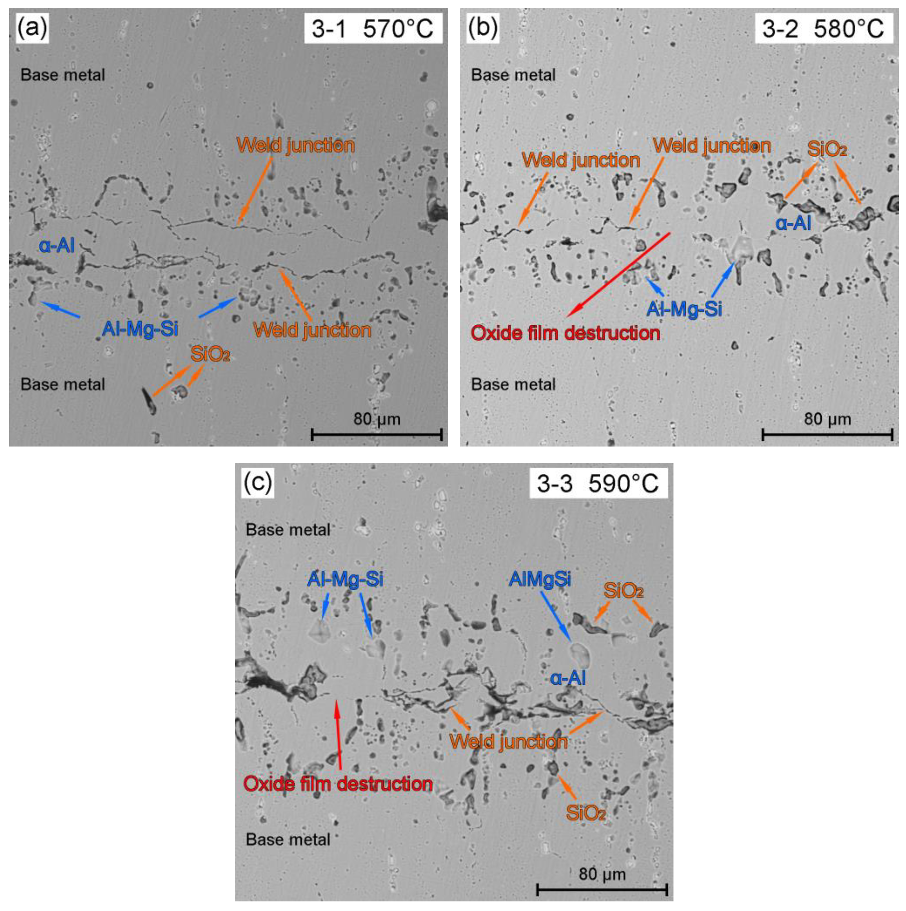
Figure 8a–c shows the SEM microstructures of the brazing joints of Al-6Cu-10Si-2Mg-10Zn (3#) brazing filler alloy at different brazing temperatures (570~590 °C). The phase composition under three conditions was similar: α-Al + Al-Mg-Si + SiO2. As shown in Figure 8a, when the brazing temperature was 570 °C, the weld junction with oxide film was relatively complete, and the film-breaking effect was not obvious. As shown in Figure 8b, when the brazing temperature rose to 580 °C, the oxide film was damaged obviously. But at the same time, oxidation intensified and a large number of oxides are produced. For 3# brazing filler, the film-breaking effect with 590 °C brazing temperature is the best. To sum up, there is a corresponding optimal film-breaking temperature for different components of brazing filler. The oxidation will also intensify with the increase of the interfacial temperature gradient, and the balance between the two corresponds to the optimal brazing temperature.
The microstructure evolution process in Figure 8 also verified the TG-TLP welding mechanism. As shown in Figure 9, in the typical TG-TLP brazing process, the change of the temperature gradient of the liquid phase caused the migration of the solid/liquid interfaces. This interface migration was a one-way movement from the cooler side to the hotter side of the brazing joint. In this process, due to the stable consumption of solute, the liquid phase had shrunk and finally cured. The morphology of solid/liquid interface formed by isothermal solidification under eutectic liquid phase was unstable, so it presented the serrated or the wavy shape. The weld junction (or fusion line) would change from two (Figure 8a) to one (Figure 8c).

3.2. Effect of Brazing Temperature on the Tensile Properties of TG-TLP Joints

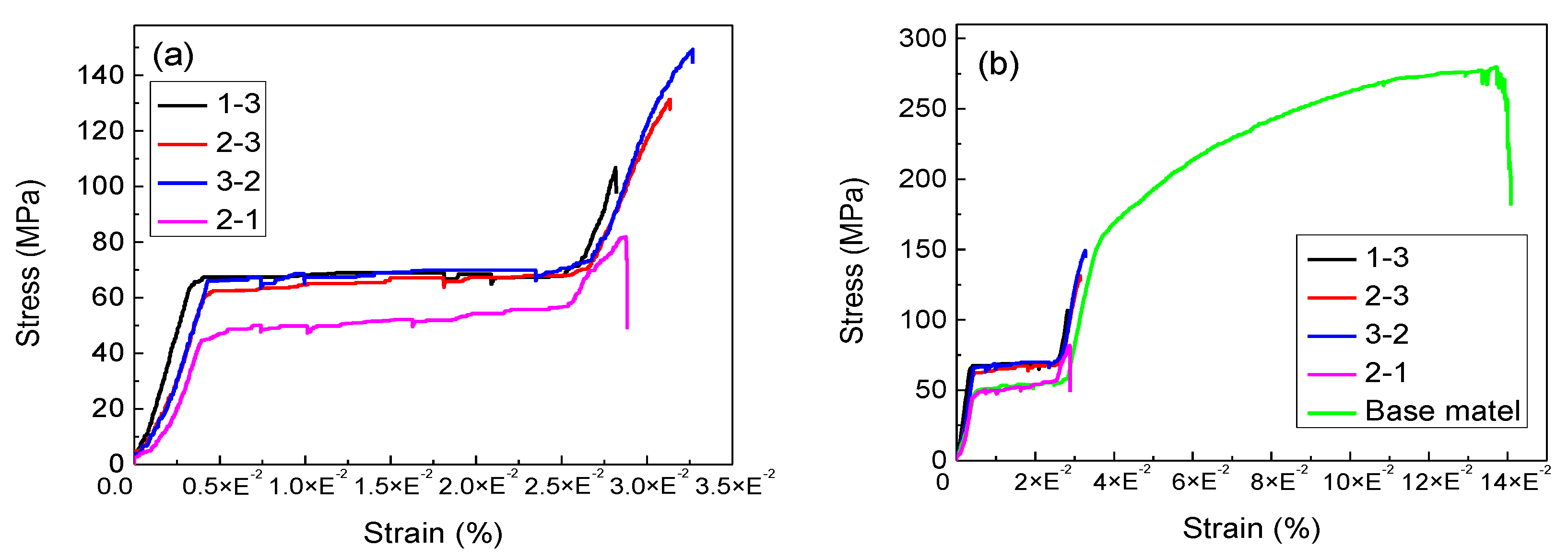
Figure 10 shows the tensile strength test results of the series of brazing joints. The corresponding tensile curves (stress-strain) of the typical samples are shown in Figure 11a, and the comparison of the tensile curves between the joints and the base metal is illustrated in Figure 11b. For 1# brazing joints, the maximum tensile strength was 113 MPa (sample 1-3) when the brazing temperature was 570 °C, and the tensile strengths under the different brazing temperatures are relatively close. For 2# brazing joints, the maximum tensile strength was 122.4 MPa (sample 2-3) when the brazing temperature was 580 °C, and the tensile strength gradually increased with the increase of brazing temperature. For 3# brazing joints, the maximum tensile strength was 147.4 MPa (sample 3-2)when the brazing temperature was 580 °C. The overall tensile strength of the brazing joint with 3# solder is relatively high. Its optimum tensile strength is 30% higher than 1# solder and 20% higher than 2# solder. The mapping quantitative detection results of oxygen element were listed in Figure 10 (the test area corresponded to Figure 4, Figure 7, and Figure 8 respectively, with the same magnification of 1000 times). Due to the imprecise determination of oxygen contents of EDS, the comparison here is only used as a judgment and reference for the overall trend of change in oxidation extent. With the increase of Al content in the filler metal (ratio of Al:Cu increased), the oxygen content in the brazing joint also showed an increasing trend. Comparing the tensile strength with the oxygen content, it can be seen that sample 2-1 with the most severe oxidation corresponds to the lowest tensile strength. Obviously, the increase of brittle oxides is not conducive to the improvement of tensile strength. For 1# and 2# samples, there is a trend that lower oxygen contents lead to higher tensile strength. For the 3# sample, although the oxygen contents (brittle oxides) increased, the oxide film had been dispersed, which had no obvious negative effect. The tensile strength is dominated by the oxide dispersion strengthening effect and the increase of material strength caused by the increase of Al:Cu ratio. Although the mapping observation area had some randomness, some laws can still be summarized. For TG-TLP brazing of 5A06, selecting the filler alloy with larger Al:Cu ratio (such as 78Al-6Cu) can obtain higher brazing joint strength, but a sufficient temperature gradient is required to exert the film-breaking effect. For the filler alloy with lower Al:Cu ratio (such as 72Al-20Cu), it is necessary to accurately control its melting point (brazing temperature) to obtain higher brazing joint strength.
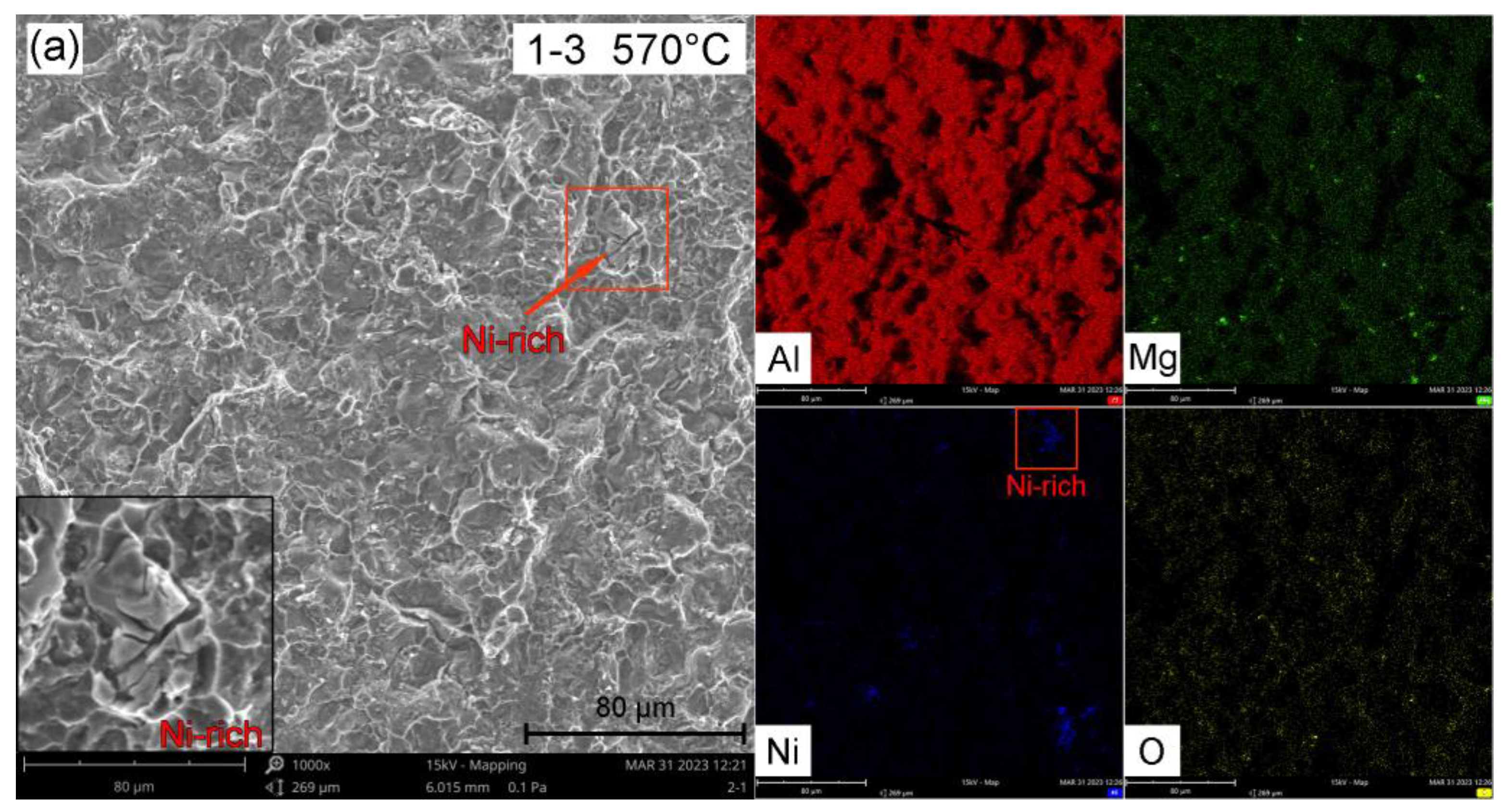
Figure 12 shows the morphology of the typical tensile fractures. As shown in Figure 12a–d, the series of fracture surfaces presented ductile fracture. As Figure 12a, there was a brittle fracture in the local area, corresponding to the Ni-rich phase (EDS mapping analysis results were shown in the illustration). Such types of brittle phases (Ti2Ni, Ni3Ti, AlNbTi2, etc) would result in the formation of welding cracks in the joint, and deteriorate the mechanical properties of joints [29,30,31]. This indicates that the Ni-enriched region is unfavorable for interfacial toughness when using Ni-containing solder. As Figure 12b, corresponds to the specimen with the lowest tensile strength, the obvious zones with a lack of bonding could be observed at the fracture surface. A large amount of Mg oxides were also distributed at the fracture (EDS analysis result was shown in the illustration). These significantly reduced the strength of TLP joints. As shown in Figure 12c,d, for the samples with relatively high tensile strength, a large number of equiaxial dimples could be observed at the fracture surface. To sum up, increasing the solder interfacial wettability and reducing the oxide contents at the phase interface were still the key to improving the interfacial bonding strength.
In this study, the highest joint strength of the samples only accounts for 52.6% of the base metal strength (280 MPa). Relevant research has conducted TLP welding on Mg-3Al-1Zn magnesium alloy, with a joint shear strength of 76.1 MPa, which could reach 92.4% of the base metal strength (82.4 MPa) [32]. The shear strength of titanium alloy (Ti6Al4V) TLP joints could reach 662.5 MPa [33]. The maximum shear stress of the high entropy alloy (HEA) TLP joint of FeCoNiTiAl and Ni-based FGH98 superalloys could get 1156 MPa [11]. Under the assistance of ultrasound, the shear strength of the TPL joint of 6061 aluminum alloy reached 95% of the base metal (=164 MPa) [14]. Reference to aluminum alloy TLP joints is limited, but it is clear that the TLP welding process and filler metal selection for 5A06 aluminum alloy need to be redesigned. The observation results of this study indicate that there is still a lot of room for improvement (the phase interface structure can be regulated), and the brazing temperature can be further accurately adjusted according to the designed solder composition (which can be combined with simulation calculations); The holding time can be controlled (reducing oxide content); The temperature gradient can be enhanced (changing the cooling method to increase the oxide film breaking effect). Based on the above, future research will focus on Al-Cu-Mg series brazing alloys. It is necessary to adjust the composition of the solder and accurately control the brazing temperature (selecting the high-entropy alloy [34] and using software such as JMatPro to calculate the liquid phase temperature and adjust the composition [35,36]), striving to complete the welding at the lowest possible temperature (to reducing oxidation). The goal is to obtain a joint with sufficient strength under non-vacuum protect) conditions as much as possible. The inevitable oxidation during the brazing process can be solved through the film-breaking effect, which requires continued attention to the regulation of the TG-TLP temperature gradient based on the appropriate brazing filler metal composition and the brazing temperature.

4. Conclusions

Three typical compositions of brazing filler alloy (1# Al-20Cu-6Si-2Ni, 2# Al-10Cu-10Si-3Mg-1Ga, and 3# Al-6Cu-10Si-2Mg-10Zn) were prepared by melting and the 5A06 aluminum alloy bar was joined by the temperature gradient transient liquid phase diffusion welding (TG-TLP) process. The effects of brazing temperature (560 °C, 570 °C, and 580 °C) on the microstructure and tensile strength of the joint were studied, and the results are summarized as follows:
(1) For different filler alloys, there was a certain brazing temperature to make the TG-TLP film-breaking effect most significant, which were 560 °C for 1#, 580 °C for 2#, and 590 °C for 3#. Compared with 1# and 2# brazing filler, 3# got the most significant film-breaking effect, and its oxide film was completely broken to scatter at the weld junction.
(2) With the increase of temperature gradient, the film-breaking effect was easier to occur, but the oxidation was intensified. The oxidation products enriched were mainly Al2O3 and SiO2 at the phase interfaces of the weld junction. Proper brazing temperature is required to obtain a reasonable temperature gradient to balance the film-breaking effect and the oxide formation. For 1# brazing filler, the optimum brazing temperature was 570 °C (tensile strength = 113.0 MPa); For 2# brazing filler, it was 580 °C (tensile strength = 122.4 MPa); For 3# brazing filler, it was 580 °C (tensile strength = 147.4 MPa).
(3) When the sample was seriously oxidized, the oxidation effect dominated the mechanical performance. The 2# sample produced serious weld joint oxidation at the brazing temperature of 560 °C, which corresponded to a significant reduction in tensile strength (only 81.4 MPa). Under the experimental conditions of this study, the maximum tensile strength of TG-TLP joints was 147.4 MPa, which corresponded to the 3# sample at the brazing temperature of 580 °C. The overall tensile strength of the brazing joint with 3# solder is relatively high. The optimum tensile strength of 3# solder is 30% higher than 1# and 20% higher than 2#.
(4) For TG-TLP welding of 5A06, the filler alloy with higher Al:Cu ratio (12:1 wt.%) needed a sufficient temperature gradient to exert the film-breaking effect, and the filler alloy with lower Al:Cu ratio (3.6:1 wt.%) needed to accurately control its melting point (brazing temperature) to avoid excessive oxidation.
The conclusions of this study can provide some reference for the brazing of other Al-Mg-based aluminum alloys. When selecting high Al:Cu ratio (12:1 wt.%) brazing materials, it is necessary to enhance gas protection. For the improvement of the strength of the joint, Mg, Si oxides, and the Ni-rich phase at the interface is unfavorable, and the quantity and the distribution uniformity of them need to be controlled.

Author Contributions

Conceptualization, data curation, resources, and writing—original draft preparation, Y.C.; methodology, writing—review and editing, Q.L., N.Z. and P.X.; Conceptualization, T.L., C.Z. and Y.H.; investigation, validation, Q.L. All authors have read and agreed to the published version of the manuscript.

Funding

This research was funded by the National Natural Science Foundation of China (No. 52065048), the State Key Laboratory of Advanced Welding and Joining, Harbin Institute of Technology (No. AWJ-22Z02), the Shanghai Science and Technology Development Funds, China (No. 20QB1402700), and Anhui Province Key Laboratory of Special Welding Technology (No. 2021SW1002).

Institutional Review Board Statement

Not applicable.

Informed Consent Statement

Not applicable.

Data Availability Statement

All data has been shown in this manuscript.

Acknowledgments

The authors acknowledge the National Defence Key Discipline Laboratory of Light Alloy Processing Science and Technology, Nanchang Hangkong University for assisting in characterization.

Conflicts of Interest

The authors declare no conflict of interest.

References

  1. Yang, X.; Chen, H.; Li, M.V. Porosity suppressing and grain refining of narrow-gap rotating laser-MIG hybrid welding of 5A06 aluminum alloy. J. Manuf. Process. 2021, 68, 1100–1113. [Google Scholar] [CrossRef]
  2. Zhang, Y.; Huang, J.; Ye, Z. An investigation on butt joints of Ti6Al4V and 5A06 using MIG/TIG double-side arc welding-brazing. J. Manuf. Process. 2017, 27, 221–225. [Google Scholar] [CrossRef]
  3. Wang, Z.; Oliveira, J.P.; Zeng, Z. Laser beam oscillating welding of 5A06 aluminum alloys: Microstructure, porosity and mechanical properties. Opt. Laser. Technol. 2019, 111, 58–65. [Google Scholar] [CrossRef]
  4. Li, Z.; Ou, L.; Wang, Y.; Li, H. Solidification Cracking Restraining Mechanism of Al-Cu-Mg-Zn Alloy Welds Using Cold Metal Transfer Technique. Materials 2023, 16, 721. [Google Scholar] [CrossRef]
  5. Yi, T.; Liu, S.; Fang, C. Eliminating hole defects and improving microstructure and mechanical properties of friction stir welded joint of 2519 aluminum alloy via TIG arc. J. Mater. Process. Technol. 2022, 310, 117773. [Google Scholar] [CrossRef]
  6. Atieh, A.M.; Cooke, K.M.; Epstein, M. Transient liquid phase (TLP) bonding as reaction–controlled diffusion. Mater. Today Commun. 2022, 33, 104293. [Google Scholar] [CrossRef]
  7. Afghahi, S.S.S.; Ekrami, A.; Farahany, S. Fatigue properties of temperature gradient transient liquid phase diffusion bonded Al7075-T6 alloy. Trans. Nonferrous Met. Soc. China 2015, 25, 1073–1079. [Google Scholar] [CrossRef]
  8. Afghahi, S.S.S.; Jafarian, M.; Paidar, M. Diffusion bonding of Al 7075 and Mg AZ31 alloys: Process parameters, microstructural analysis and mechanical properties. Trans. Nonferrous Met. Soc. China 2016, 26, 1843–1851. [Google Scholar] [CrossRef]
  9. Fu, Z.H.; Yang, B.J.; Shan, M.L. Hydrogen embrittlement behavior of SUS301L-MT stainless steel laser-arc hybrid welded joint localized zones. Corros. Sci. 2020, 164, 108337. [Google Scholar] [CrossRef]
  10. Zhu, Z.Y.; Liu, Y.L.; Gou, G.Q. Effect of heat input on interfacial characterization of the butter joint of hot-rolling CP-Ti/Q235 bimetallic sheets by Laser + CMT. Sci. Rep. 2021, 11, 10020. [Google Scholar] [CrossRef]
  11. Yuan, L.; Xiong, J.T.; Ren, J. Ultrastrong and ductile transient liquid phase (TLP) bonding joints reinforced by ordered multi-precipitates. Compos. Part B Eng. 2022, 231, 109568. [Google Scholar] [CrossRef]
  12. Bobzin, K.; Bosse, L.; Brandenburg, A. Transient Liquid Phase Bonding. In Montage Hybrider Mikrosysteme; Springer: Berlin/Heidelberg, Germany, 2005; pp. 65–78. [Google Scholar] [CrossRef]
  13. Guo, W.; Leng, X.; Luan, T. Ultrasonic-promoted rapid TLP bonding of fine-grained 7034 high strength aluminum alloys. Ultrason. Sonochem. 2017, 36, 354–361. [Google Scholar] [CrossRef] [PubMed]
  14. Jia, Q.; Lai, Z.; Zhang, H. Mechanism of ultrasonic-assisted transient liquid phase bonding of 6061 Al alloy with cladded Zn-Al alloy in air. J. Mater. Process. Technol. 2020, 286, 116823. [Google Scholar] [CrossRef]
  15. Assadi, H.; Shirzadi, A.A.; Wallach, E.R. Transient liquid phase diffusion bonding under a temperature gradient: Modelling of the interface morphology. Acta Mater. 2001, 49, 31–39. [Google Scholar] [CrossRef]
  16. Jabbareh, M.A.; Assadi, H. Modelling of microstructure evolution in transient-liquid-phase diffusion bonding under temperature gradient. Scripta Mater. 2009, 60, 780–782. [Google Scholar] [CrossRef]
  17. Yu, C.H.; Zhu, Y.; Kang, H. Influence of Alloying Element to Property in Al-Si-Cu-Ni Low Melting -Point Solder. Weld. Joi. 2002, 11, 21–36. Available online: https://d.g.wanfangdata.com.cn/Periodical_hj200211007.aspx (accessed on 17 May 2023).
  18. Chang, S.Y.; Tsao, L.C.; Li, T.Y. Joining 6061 aluminum alloy with Al–Si–Cu filler metals. J. Alloys Compd. 2009, 488, 174–180. [Google Scholar] [CrossRef]
  19. Zhang, M.; Tian, Y.; Zheng, X. Research Progress on Multi-Component Alloying and Heat Treatment of High Strength and Toughness Al–Si–Cu–Mg Cast Aluminum Alloys. Materials 2023, 16, 1065. [Google Scholar] [CrossRef]
  20. Lah, N.A.C.; Hussin, M.H. Role of Mg in porous oxide scale growth formation on welded Al 6061 (Al-Mg-Si). Mater. Today Proc. 2023, 75, 99–110. [Google Scholar] [CrossRef]
  21. Ma, C.; Xue, S.; Wang, B. Study on novel Ag-Cu-Zn-Sn brazing filler metal bearing Ga. J. Alloys Compd. 2016, 688, 854–862. [Google Scholar] [CrossRef]
  22. Zhang, Z.; Li, Y.; Li, H. Effect of high Cu concentration on the mechanical property and precipitation behavior of Al–Mg–Zn-(Cu) crossover alloys. J. Mater. Res. Technol. 2022, 20, 4585–4596. [Google Scholar] [CrossRef]
  23. Li, Z.; Zhang, Y.; Li, H. Liquation Cracking Susceptibility and Mechanical Properties of 7075 Aluminum Alloy GTAW Joints. Materials 2022, 15, 3651. [Google Scholar] [CrossRef] [PubMed]
  24. Li, H.X.; Feng, Y.D.; Shen, W.J. Microstructure and mechanical properties of Cu/Al joints brazed using (Cu, Ni, Zr, Er)-modified Al−Si filler alloys. Trans. Nonferrous Met. Soc. China 2022, 32, 3623–3634. [Google Scholar] [CrossRef]
  25. Wang, Z.J.; Gao, Z.; Wang, P. Investigation on Process of Vacuum Brazing of 6063 Aluminum Alloy. Hot W. Tech. 2019, 48, 72–76. [Google Scholar] [CrossRef]
  26. Li, H.; Zhu, K.; Liu, Q. Microstructural Characterization of the As-Cast and Homogenized Al-Cu-Mg-Ag Alloy. Materials 2023, 16, 433. [Google Scholar] [CrossRef]
  27. Yuan, B.; Li, G.; Guo, M. Synergy of Ni micro-alloying and thermomechanical processing in Al-Mg-Si-Cu-Zn-Fe-Mn alloys with enhanced bendability. J. Mater. Res. Technol. 2021, 15, 5059–5077. [Google Scholar] [CrossRef]
  28. Han, J.Q.; Wang, J.S.; Zhang, M.S. Relationship between amounts of low-melting-point eutectics and hot tearing susceptibility of ternary Al−Cu−Mg alloys during solidification. Trans. Nonferrous Met. Soc. China 2020, 30, 2311–2325. [Google Scholar] [CrossRef]
  29. Deng, H.B.; Chen, Y.H.; Jia, Y.L. Microstructure and mechanical properties of dissimilar NiTi/Ti6Al4V joints via back-heating assisted friction stir welding. J Manuf. Process. 2021, 64, 379–391. [Google Scholar] [CrossRef]
  30. Chen, Y.H.; Sun, S.W.; Zhang, T.M. Effects of post-weld heat treatment on the microstructure and mechanical properties of laser-welded NiTi/304SS joint with Ni filler. Mat. Sci. Eng. A 2020, 771, 138545. [Google Scholar] [CrossRef]
  31. Chen, Y.H.; Mao, Y.Q.; Lu, W.W. Investigation of welding crack in micro laser welded NiTiNb shape memory alloy and Ti6Al4V alloy dissimilar metals joints. Opt. Laser Technol. 2017, 91, 197–202. [Google Scholar] [CrossRef]
  32. Sun, D.Q.; Cu, X.Y.; Liu, W.H. Transient liquid phase bonding of magnesium alloy (Mg–3Al–1Zn) using aluminium interlayer. Mat. Sci. Eng. A 2005, 391, 29–33. [Google Scholar] [CrossRef]
  33. Ghorbani, H.R.; Mosallanejad, M.H.; Atapour, M. Hybrid additive manufacturing of an electron beam powder bed fused Ti6Al4V by transient liquid phase bonding. J. Mater. Res. Technol. 2022, 20, 180–194. [Google Scholar] [CrossRef]
  34. Fang, J.X.; Wang, J.X.; He, H.T. Microstructure evolution and deformation behavior during stretching of a compositionally inhomogeneous TWIP-TRIP cantor-like alloy by laser powder deposition. Mat. Sci. Eng. A 2022, 847, 143319. [Google Scholar] [CrossRef]
  35. García-García, V.; Mejía, I.; Hernández-Belmontes, H. Computational simulation of thermo-mechanical field and fluid flow and their effect on the solidification process in TWIP steel welds. J. Manuf. Process. 2022, 84, 100–120. [Google Scholar] [CrossRef]
  36. Tan, C.; Zang, C.; Xia, H. Influence of Al additions in Zn–based filler metals on laser welding–brazing of Al/steel. J. Manuf. Process. 2018, 34, 251–263. [Google Scholar] [CrossRef]
Figure 1. Brazing filler alloy: (a) as cast bar, (b) slice.
Metals 13 01048 g001
Figure 2. Brazing fixture: (1) brazing parts, (2) induction coil, (3) water cooling device, (4) V block, (5) V block support, (6) slider, (7) guide rail mechanism, (8) cylinder device, (9) cylinder support, (10) fixture base, (11) base support plate, (12) side support plate.
Metals 13 01048 g002
Figure 3. Sampling location and dimension (in mm) for the tensile test of the metal bar.
Metals 13 01048 g003
Figure 4. SEM images of the brazing joints with Al-20Cu-6Si-2Ni brazing filler alloy at different brazing temperatures: (a) 550 °C; (b) 560 °C; (c) 570 °C.
Metals 13 01048 g004
Figure 5. Composition of flocculent mixed phase: (a) SEM images of the phase composition, (bg) element mapping analysis of Al, Cu, Mg, Ni, Si, and O.
Metals 13 01048 g005
Figure 6. Oxide film distribution and phase composition analysis at the weld junction (brazing temperature of 570 °C): (a) SEM images of the weld junction, (b) element mapping analysis of O, (c) mapping element distribution of with multiple elements, (d) elements quantitative analysis of oxide film.
Metals 13 01048 g006aMetals 13 01048 g006b
Figure 7. SEM images of the brazing joints with Al-10Cu-10Si-3Mg-1Ga brazing filler alloy at different brazing temperatures: (a) 560 °C; (b) 570 °C; (c) 580 °C.
Metals 13 01048 g007
Figure 8. SEM images of the brazing joints with Al-6Cu-10Si-2Mg-10Zn brazing filler alloy at different brazing temperatures: (a) 560 °C; (b) 570 °C; (c) 580 °C.
Metals 13 01048 g008
Figure 9. Formation mechanism of conventional TLP and TG-TLP diffusion bonding.
Metals 13 01048 g009
Figure 10. Tensile strength and corresponding measured oxygen content of TG-TLP welded joints.
Metals 13 01048 g010
Figure 11. Stress-strain curves of the tensile samples: (a) the typical samples of 1#~3#, (b) the comparison to the base metal.
Metals 13 01048 g011
Figure 12. Fracture morphology of the tensile samples: (a) 1-3, 570 °C; (b) 2-1 560 °C; (c) 2-3 580 °C; (d) 3-2, 580 °C.
Metals 13 01048 g012aMetals 13 01048 g012b
Table 1. Chemical composition of 5A06 alloy and the brazing filler alloys (wt.%).
CompositionSiFeCuMnMgAlZnTiNiGa
5A06≤0.400~0.4≤0.100.5
~0.8
5.8
~6.8
Bal.≤0.100.02
~0.10
1# solder5.5
~6.0
19.0
~20.0
Bal.2.0
~2.5
2# solder9.0
~10.0
9.0
~10.0
2.5
~3.0
Bal.1.0
~1.2
3# solder9.0
~10.0
5.0
~6.0
1.5
~2.0
Bal.9.0
~10.0
Table 2. TLP brazing parameters of 5A06 with series Al-Cu-Si brazing filler alloys with a soaking time of 30 min and a load of 0.1 MPa.
No.Composition (wt.%)Brazing Temperature (°C)
1-1Al-20Cu-6Si-2Ni550
1-2Al-20Cu-6Si-2Ni560
1-3Al-20Cu-6Si-2Ni570
2-1Al-10Cu-10Si-3Mg-1Ga560
2-2Al-10Cu-10Si-3Mg-1Ga570
2-3Al-10Cu-10Si-3Mg-1Ga580
3-1Al-6Cu-10Si-2Mg-10Zn570
3-2Al-6Cu-10Si-2Mg-10Zn580
3-3Al-6Cu-10Si-2Mg-10Zn590
Disclaimer/Publisher’s Note: The statements, opinions and data contained in all publications are solely those of the individual author(s) and contributor(s) and not of MDPI and/or the editor(s). MDPI and/or the editor(s) disclaim responsibility for any injury to people or property resulting from any ideas, methods, instructions or products referred to in the content.