Article

Hot Corrosion Behavior of Inconel 625 in Na2SO4 and V2O5 Molten Salt System

1
School of Materials Science and Engineering, Lanzhou University of Technology, Lanzhou 730050, China
2
Lanzhou LS Group Co., Ltd., Casting ang Forging Branch, Lanzhou 730314, China
3
State Key Laboratory of Advanced Processing and Recycling of Non-Ferrous Metals, Lanzhou University of Technology, Lanzhou 730050, China
*
Authors to whom correspondence should be addressed.
Metals 2023, 13(6), 1069; https://doi.org/10.3390/met13061069
Submission received: 8 May 2023 / Revised: 27 May 2023 / Accepted: 30 May 2023 / Published: 2 June 2023
(This article belongs to the Special Issue Multifunctional Hard Coatings on Metals)

Abstract

:
This study aimed to examine the corrosion behavior of Inconel 625 in a molten salt system of sodium sulfate and vanadium pentoxide at varying temperatures and durations. The corrosion products, microstructure, and element distribution of hot extruded Inconel in Na2SO4 and V2O5 molten salt systems were analyzed using X-ray diffraction (XRD), scanning electron microscopy (SEM), and energy-dispersive spectroscopy (EDS) analyses. This study demonstrates that corrosion of the alloy increases with time at a constant temperature. During the initial stage of corrosion, the surface of the alloy is primarily composed of a dense oxide layer consisting of Cr2O3 and NiO. However, after exposure to the salt bath for 24 h, a chemical reaction occurs between the alloy and vanadium (V), resulting in the formation of CrVO4 and Ni3V2O8. Furthermore, the intrusion of sulfur (S) element into the matrix leads to the formation of internal sulfides, including Ni-, Cr-, and Mo-based sulfides, which accelerate intergranular and intracrystalline corrosion. As the corrosion temperature rises, the surface microstructure of the corrosion layer transforms from powder to salt particles and then to massive particles. The corrosion products exhibit a clear stratification, while the alloy undergoes simultaneous oxidation and vulcanization processes.

1. Introduction

Since the end of the 20th century, research studies on 700 °C, supercritical, oil-fired power generation technology have been continuously conducted. The goal is to build 37.5 MPa/700 °C advanced ultra-supercritical (A-USC) demonstration power stations to improve thermal efficiency. A 700 °C class A-USC thermal power unit requires high-temperature materials with good high-temperature creep strength, excellent resistance to steam oxidation on the inner wall of the tube, and excellent processing performance [1]. Inconel 625 has good corrosion resistance and oxidation resistance in high-temperature and high-pressure environments; therefore, it has been considered to be one of the excellent candidate materials for the key components of advanced supercritical boiler superheaters and reheaters [2,3,4,5,6]. However, advanced supercritical oil-fired boilers usually use high-sulfur and high-vanadium crude oil as fuel, and the sulfur and vanadium in the fuel will cause a high-temperature corrosion of the boiler [7,8,9,10]. In order to simulate the service of Inconel 625 in high-sulfur and high-vanadium corrosion environments at high temperatures, a large number of studies [11,12,13,14] have been carried out, which have mainly focused on the influence of corrosive media and temperature on the corrosion behavior; these studies have proposed corrosion models such as the “acid-base melting mechanism” and “vulcanization mechanism”.
Fresnillo et al. [15,16] found that a thin chromium-based oxide layer was formed on the surface of the alloy after long-term oxidation in Ar-50% H2O at 700–800 °C. The outside of the oxide layer is a Cr/Mn spinel, and the inside is SiO2. The phases found in the bulk alloy after long-term exposure were mainly the needle-shaped δ-Ni3(Nb, Mo) phase, μ-phase, and Si-rich η-M6C carbide. Guo et al. [17,18] investigated the hot corrosion behavior of iron- and nickel-based alloys in mixed sulfuric acid molten salt and found that internal vulcanization–internal oxidation is the main damage form of hot corrosion for these alloys. When hot corrosion occurs in a nickel base alloy, a layer of Cr2O3 oxide film will first generate on the surface of the alloy; however, sulfur element will invade into the alloy through this layer of oxide film and cause internal sulfuration. Lu et al. [19] studied the hot corrosion behavior of a high-chromium nickel-based alloy in molten sulfate and found that the oxidation and sulfurization of the alloy were carried out simultaneously. With the increase in temperature, the depth and size of oxidation and inner sulfurization zone increased. Ye et al. [20] analyzed the corrosion mechanism of Inconel 625 in mixed salt sulfuric acid for 60 h using the salt layer method. The obvious internal oxidation and internal sulfide phenomenon was observed because the O and S elements had obvious erosion, which provided a theoretical basis for the sulfate corrosion resistance of the nickel base alloy. However, the corrosion behavior in the later stage was not deeply explored due to the short experimental time.
There are currently two views on the mechanism of vanadium corrosion: a. Corrosion caused by the destruction of the oxide film on the metal surface by the molten vanadium with a low melting point: Tiwari [21] studied the chemical reaction between NaSO4 and V2O5, which mainly produced low-melting vanadates and released SO3 at the same time.
N a 2 S O 4 + V 2 O 5 2 N a V O 3 + S O 3
When the ratio of Na/V is different, the products are also different:
2 N a 2 SO 4 + 4 V 2 O 5 2 N a V O 3 + N a 2 O · 3 V 2 O 5 + 2 SO 3
2 N a 2 S O 4 + 9 V 2 O 5 Na 2 O · 6 V 2 O 5 + N a 2 O · 3 V 2 O 5 + 2 S O 3
Foster et al. [22] Studied the Na2SO4–V2O5 system theoretically from the perspective of phase equilibrium. The results show that the potentially corrosive substance in the putty are NaVO3 and Na2O·3V2O5; when the molar ratio of Na/V is 1:6, a highly corrosive vanadate Na2O·V2O4·5V2O5 will be formed. This compound will absorb oxygen during melting and release oxygen during solidification:
1 2 O 2 + N a 2 O · V 2 O 4 · 5 V 2 O 5 Na 2 O · 6 V 2 O 5
These low-melting vanadium compounds can dissolve the oxides on the metal surface. For example, NaVO3 can destroy the protective oxide layer on the surface of Ni–Cr alloy through the following reaction, thereby causing accelerated corrosion:
2 N a V O 3 + N i O N a 2 N i O 2 + V 2 O 5
2 N a V O 3 + C r 2 O 3 2 C r V O 4 + N a 2 O
Oxygen absorbed by molten vanadate further accelerates metal oxidation:
Cunningham and Brasunas expanded the research results of Foster [23]. It was found that the most corrosive putty contains 15–20% Na2SO4. At the same time, the vanadate absorbs oxygen in an aerobic environment and releases oxygen during solidification, and the degree of corrosion is related to the oxygen absorption of the mixture. The reaction formula is as follows:
m N a 2 O · n V 2 O 5 m N a 2 O · n p V 2 O 5 · p V 2 O 4 + 1 2 p O 2
Although nickel-based alloys have been deeply studied in a sulfur corrosion environment, there are few research studies on the high-temperature vulcanization and vanadium corrosion of nickel-based alloys. In this work, in order to study the corrosion mechanism of Inconel 625 in a supercritical oil boiler, the corrosion behavior of Inconel 625 in a sodium sulfate and vanadium pentoxide molten salt system at different temperatures and times was characterized using X-ray diffraction (XRD) (BRKR Inc., Karlsruhe, Germany), scanning electron microscope (SEM) (JEOL Inc., Tokyo, Japan), and an energy-dispersive spectrometer (EDS) (JEOL Inc., JPN).

2. Experiment

2.1. Materials

The chemical composition of Inconel 625 is listed in Table 1. The specimens were first deformed by the following extrusion parameters: extrusion ratio 3.61, extrusion temperature 1163 °C, extrusion speed 45 mm/s, and lubrication with glass lubricant. Then, they were cut using wire electrical discharge machining to gain the size of 10 × 10 × 5 mm, and then the burrs, debris, and scratches on the surface of specimens were polished using 2000, 3000, and 5000 grit silicon carbide papers. Finally, the sample was washed with acetone and alcohol.

2.2. Corrosion Method and Weight Loss Measurement

The hot corrosion tests of polished samples were carried out using the crucible landfill method. First, Na2SO4 and V2O5 powders were mixed into corundum crucible at the proportion of 20% Na2SO4 and 80% V2O5. Then, the samples were immersed in the mixed molten salt powders. Subsequently, the crucible was heated in a box-type resistance furnace at 700 °C, 750 °C, and 800 °C for 24, 48, 72, 96, and 120 h, respectively. The specimens were taken out of the furnace and cooled to room temperature with the molten salt after the immersion tests. Vanadium compounds on the surface of the corroded specimens were rinsed with 10% sodium hydroxide (NaOH) aqueous solution [24]. The corrosion rate of the specimens was calculated using the weight loss method:
v l o s s = m 0 m 1 s t
where v l o s s is the corrosion rate when using the weight-loss method, measured in g/(cm2 × h); m0 is the initial mass of the specimen in grams; m1 is the mass of the specimen after corrosion in grams; s is the initial area of the specimen in cm2; and t is the corrosion time in hours. The metal corrosivity rating is usually determined according to the corrosion depth. Equation (9) was applied for converting the corrosion rate from the weight loss method to depth method:
v d e p t h = v l o s s × 24 × 356 1000 × ρ = 8.76 v l o s s ρ
where v d e p t h is the corrosion rate when using the depth method and ρ stands for the metal density; in the equation, the unit of v d e p t h is mm/a. “mm/a” is the unit of the corrosion rate, where “mm” is the millimeter representing the depth of corrosion and “a” is the year representing the corrosion time.

2.3. Surface Characterization Method

The hot corrosion experiment was conducted using the crucible method. A processed sample was placed into a crucible along with 3 g of Na2SO4 and 17 g of V2O5, both having a purity of at least 99.9%. The crucible was then heated in an electric furnace at a rate of 5 °C/min until it reached 700 °C (750 °C and 800 °C temperatures were also used). Atmospheric pressure and constant temperature hot corrosion tests were then performed. Samples were collected every 24 h, cooled in air to room temperature, cleaned with alcohol, dried, and weighed. The corrosion products were analyzed using a D8ADVANCE X-ray diffractometer. The corrosion morphology and composition of the samples were analyzed using a JSM-6700 field emission scanning electron microscope (SEM) and EDAX spectrometer, and a cross-section of the sample after corrosion was observed using an SEM.

3. Results and Discussion

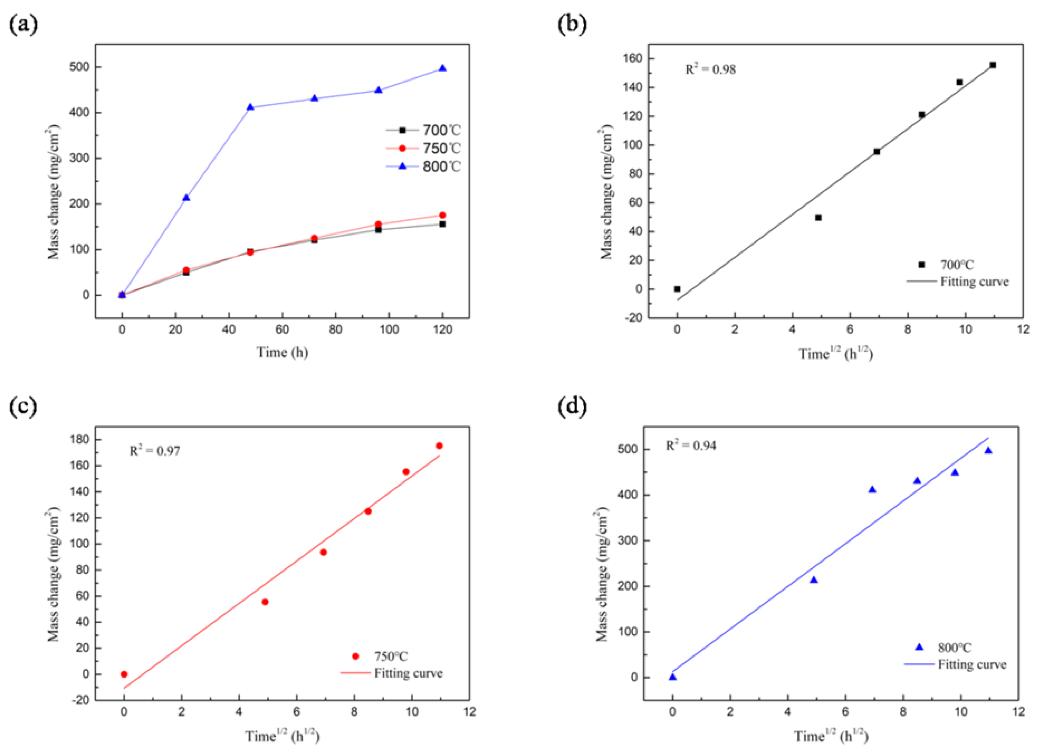
3.1. Evaluation of Hot Corrosion Rate

As shown in Figure 1a, the three curves represent the corrosion rates of the samples at 700 °C, 750 °C, and 800 °C, respectively, where the X-axis of the coordinate system is time, in hours; the Y-axis of the coordinate system represents the mass change of the sample, expressed in mg/cm2. The corrosion curves of the alloy at 700 °C and 750 °C conform to the parabola law, and the corrosion rate at 700 °C and 750 °C is obviously lower than that at 800 °C. As shown in Figure 1b–d, the corrosion kinetics curve within 48 h of 800 °C corrosion is close to the linear law.
In high-temperature corrosive environments, alloys generate an oxide protective film to safeguard the alloy substrate. However, corrosion gradually damages and consumes the oxide film. This process involves high-temperature oxidation, the dissolution of the oxide layer, re-oxidation, and re-dissolution. At 800 °C, if the corrosion time prolongs, the Cr2O3 on the material surface gradually decreases, indicating that the protective oxide film, such as Cr2O3, which is produced by the extruded Inconel 625 alloy during 800 °C corrosion, is not sufficient to resist the corrosion of V2O5 and Na2SO4. As a result, Cr2O3 gradually dissolves and is consumed during the corrosion process, allowing the S element to invade the matrix and generate sulfide. The study found that the protective effect of the oxide film is good at 700 °C and 750 °C as it prevents the corrosive medium from coming into contact with the substrate. As shown in Figure 1, the corrosion rate is much higher at 800 °C. At this temperature, there is no formation of a Cr2O3 oxide layer in the initial stage of corrosion, resulting in a faster corrosion rate. However, a protective Cr2O3 oxide layer is formed in the later stage of corrosion, resulting in a change from a straight line to a parabolic line. The corrosion rate of the alloy according to Equation (9) was calculated to be 0.135 mm/a at 700 °C for 120 h, 0.152 mm/a at 750 °C for 120 h, and 0.431 mm/a at 800℃ for 120 h, respectively. In light of the ten grade evaluation system, the corrosion rate is grade six.

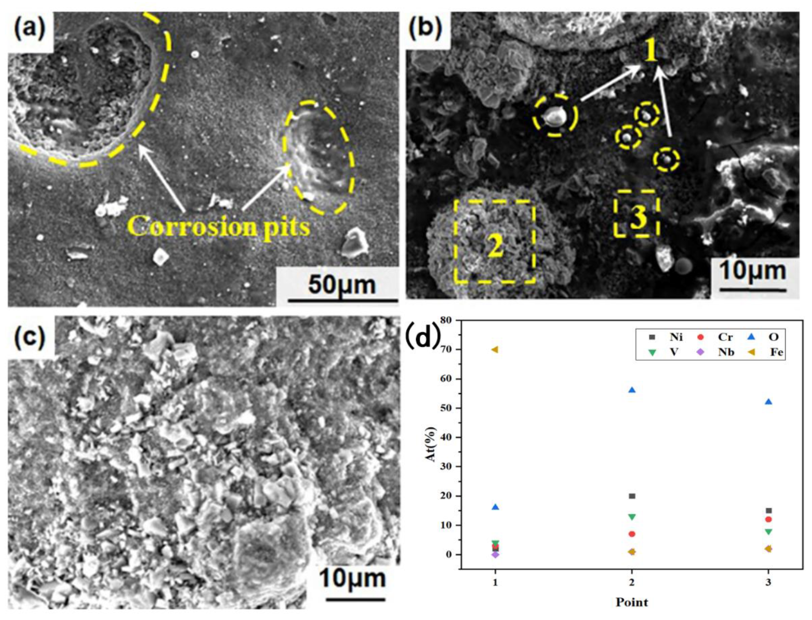
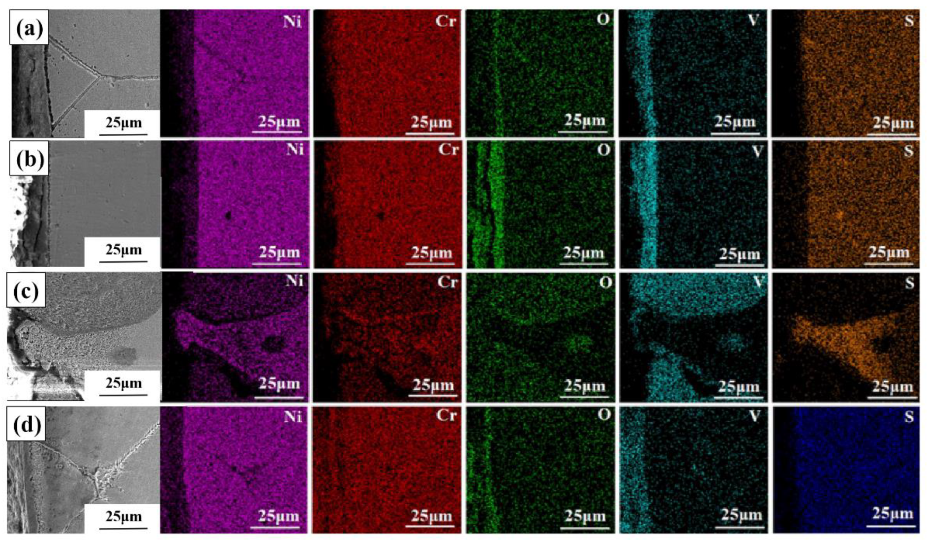
3.2. Hot Corrosion Morphology Analysis

Figure 2 shows the corrosion morphology of the specimens at 700 °C at different times under 20% Na2SO4 and 80% V2O5 molten salt. As can be seen from the corrosion morphologies of samples at 700 °C for 24 h, a flat and dense corrosion layer is formed on the surface with a trapezoidal distribution. There is no obvious granular oxide distribution of the surface. After 48 h of corrosion, a gap occurs between the corrosion layer and substrate, and an obvious corrosion belt appears, leading to poor bonding with the substrate. At the same time, irregularly shaped particles are distributed over the corrosion belt. According to the element distribution after the corrosion was characterized using EDS analysis, the corrosion layer mainly contains Ni, Cr, O, and V elements. Compared with the surface, the content of Ni elements in the inside of the corrosion belts increases while the content of Cr elements decreases, indicating that the granular material is a vanadate containing Ni (CrVO4). After 120 h of corrosion, the corrosion layers become loose, and the corrosion layers in some corrosion areas peel off due to the influence of thermal stress.
Figure 3 illustrates the morphology of the sample after corrosion at 750 °C under a molten salt mixture of 20% Na2SO4 and 80% V2O5 for different time intervals. The corrosion morphology of the sample after 24 h at 750 °C reveals the formation of a flat and dense corrosion layer with a trapezoidal distribution on the surface. Additionally, there is no apparent granular oxide distribution on the surface. An energy spectrum analysis was conducted on various areas of the corrosion layer 48 h after the sample’s corrosion (Figure 3b,d). The analysis revealed that the precipitates in the area are rich in O and V elements. It was hypothesized that the formation of vanadate Ni3V2O8 containing Ni occurred in this region. After being subjected to corrosion at a temperature of 750 °C for a period of 120 h, the surface of the sample displays a corrosion layer that mostly consists of loose powder particles. The presence of pits in certain areas suggests that the sample’s interior is relatively dense, albeit with some cracks, as depicted in Figure 3c.
Figure 4 shows the corrosion morphology of the specimens at 800 °C at different times under 20% Na2SO4 and 80%V2O5 molten salt. Figure 4a shows the corrosion morphology of extruded Inconel 625 alloy in a V2O5–Na2SO4 system at 800 °C for 24 h. The corrosion layer is relatively flat, but there are pits on the surface, along with the distribution of spherical iron segregation and massive Ni3(VO4)2 particles. After corrosion at 800 °C for 24 h, pits appear on the surface of the corrosion layer, the surface is in a loose and porous state, and a large number of corrosion particles are distributed on the surface. After 48 h of corrosion, most of the particles on the surface of the corrosion layer gather into clusters, and a small number of particles are dispersed on the surface of the corrosion layer. As written in the paper by Wang et al., with the increase in corrosion time, Na2SO4 further decomposes to form O2− at the molten salt/substrate interface according to Equation (10) throughout the hot corrosion process [25]. Subsequently, a large number of Cr2O3 oxide films decompose and react with molten salt to form vanadates. NiO and Cr2O3 combine to form NiCr2O4 oxide with a spinel structure on this basis; this phenomenon also appeared in the paper by Malafaia et al. [26].
S O 4 2 = S O 2 + 1 2 O 2 + O 2
Moreover, spheroidal iron segregation (one point in Figure 4b) can be observed inside the substrate, which is exposed, cracked, and porous due to the exfoliation of the corrosion layers and oxidation layers. After corrosion for 120 h at 800 °C, the surface of the sample is rugged and undulating, showing mountain-shaped characteristics, and a large number of massive and granular corrosion products are formed.
The cross-sectional micrographs of the sample in the molten salt system of 20% Na2SO4 and 80% V2O5 at different temperatures with different corrosion times are shown in Figure 5. The corrosion layer is a dense oxide layer and combines well with the substrate at 700 °C for 24 h. As for 48 h, corrosion occurs at the grain boundary, and the corrosion layer is a Cr-rich layer with crack initiation. After 120 h of corrosion, the grain boundary corrosion is more serious. In addition, there are obvious stratification phenomena in the corrosion layer and corrosion particles in the outer layer, and the corrosion cracks in the inner layer gradually expand into large spallation.
Compared with 700 °C, after corrosion at 800 °C for 24 h, it can be seen that the corrosion is a porous oxide layer and that there are a large number of corrosion voids in the inner corrosion layer. The cross-section morphology of the samples after 48 h shows different corrosion zones (Figure 5e), where the corrosion products are relatively dense in zone A, abundant voids in zone B, and a denser film between zone A and zone B; the alloy substrate is in zone C. The intergranular corrosion can be clearly observed in the corrosion section diagram of the samples after 120 h.
The phenomenon described above is due to the dissolution of the oxide layer by the corrosive medium and thermal stress during the corrosion process, which causes an oxidation layer void, indentation, and other weak links. So that the S element can corrode the substrate through the oxide layer, it regenerated the oxide film and substrates, repeating until the substrate surface area of the Cr element was consumed.
Simultaneously, the V2O5 and O2− quickly convert to V O 4 3 at the interface of the molten salt according to Equation (11). However, the undissolved V2O5 and vanadate have strong acidity that can dissolve the protective oxide film that is formed on the surface of the alloy [27,28,29].
V 2 O 5 + 3 O 2 = 2 V O 4 3
The experimental results schematically show that the dissolution rate of molten salt is faster in the first 24 h of hot corrosion. Not only was the Cr2O3 oxide film quickly dissolved, but the nickel was also directly involved in the hot corrosion, forming a rich area of chemical dissolution corrosion. During the period of 24 h to 120 h, a loose oxide layer formed on the surface of the sample because of the continuous accumulation of NiO, Cr2O3, and other corrosion products, which could resist the direct invasion of molten salt. To some extent, the loose oxide layer is beneficial to the formation of a continuous protective oxide film, whose hot corrosion process mainly includes Equation (12).
S O 4 2 + 9 2 N i = 3 N i O + 1 2 N i 3 S 2 + O 2

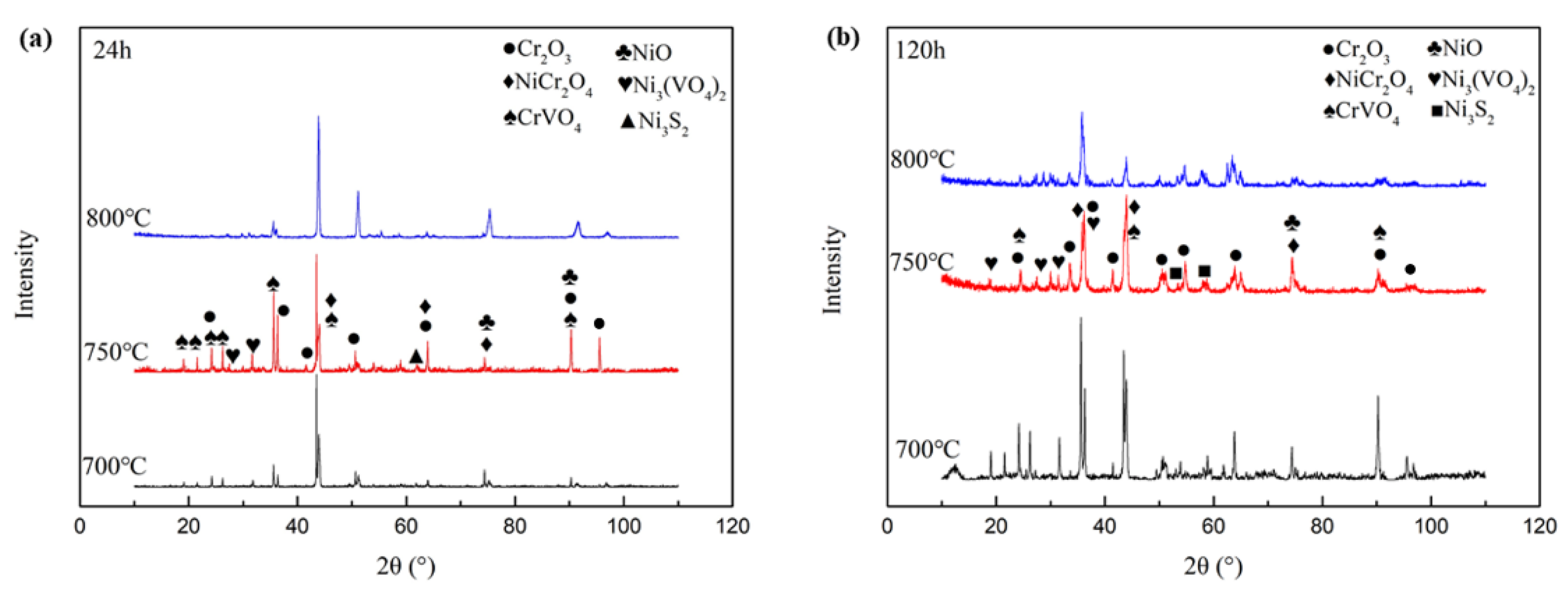
3.3. Hot Corrosion Products Analysis

The X-ray diffraction pattern of corrosion products on the sample surface is shown in Figure 6. The main diffraction peaks are the metal substrate, and the corrosion products are mainly vanadate, oxide, and sulfide. The diffraction peaks of Cr2O3, Ni3V2O8, and CrVO4 are stronger than those of 700 °C and 800 °C after corrosion at 750 °C for 24 h, and the diffraction peaks of NiCr2O4 are more obvious at high temperature. After 120 h of corrosion, the type of corrosion products did not obviously change; however, with the extension of corrosion time, the intensity of the diffraction peak of some phases was different. The intensity of diffraction peak Cr2O3 after corrosion at 700 °C for 120 h is stronger than that after corrosion at 750 °C and 800 °C for 120 h, and the diffraction peak intensity of sulfide after corrosion at 800 °C for 120 h is also more obvious than that after corrosion at 700 °C and 750 °C. When the corrosion temperature is 700 °C, the content of Cr2O3 obviously increases with the increase in corrosion time, and the vanadate of Ni and Cr increases. At 800 °C, the content of Cr2O3 decreases, and the sulfide content of Ni, Cr, and Mo increases with the increase in corrosion time.
Figure 7 shows the distribution of cross-sectional corroded surface elements after corrosion at different temperatures and times in 20% Na2SO4 and V2O5 molten salt. It is obvious that after the corrosion at 700 °C for 48 h, the corrosion layer was mainly composed of O elements, V elements, and a small amount of Cr elements. After 120 h of corrosion, with the increase in O elements, V elements, and Cr elements in the corrosion layer, corrosion occurred at the grain boundary.
The cross-section diagram of the corroded sample at 800 °C for 24 h reveals the presence of numerous holes in the corroded layer. Additionally, the content of Cr in the corroded layer and matrix below it is substantially reduced, indicating a significant consumption of Cr. The corrosion layer is primarily composed of sulfide corrosion, as evidenced by the enrichment of Ni, S, and Mo elements. In the event of corrosion, an oxide layer forms on the surface to safeguard the matrix from further corrosion. However, due to the corrosive medium and thermal stress, weak links such as holes, pits, and cracks appear in the oxide layer. This allows element S to pass through the oxide layer and corrode the matrix. The matrix will then regenerate the oxide film, and the process repeats until the Cr element in the surface area of the substrate is exhausted. S continues to vulcanize with the Ni and Mo elements in the substrate, resulting in a sulfide corrosion layer between the oxide film and the substrate. The failure to detect the enrichment of V and O elements outside the enrichment area of S elements may be attributed to the spallation of the oxide layer in certain areas under the influence of external force or thermal stress. This exposes the sulfide accumulated corrosion layer to the surface, leading to the undetected enrichment area of the V and O elements.
Nevertheless, after the corrosion at 800 °C for 48 h, the corrosion surface is evidently stratified. From the section diagram of the sample in Figure 5e and Figure 7c, it can be concluded that there are mainly V elements and O elements in region A, as well as a few Cr elements and Mo elements; region B mainly contains S element. When taken together with the XRD analysis, region A is the vanadium corrosion area, region B is the sulfur corrosion area, and region C is the alloy substrate (Figure 5e), and the dense film between zone A and B is mainly composed of Cr2O3. The results indicate that vanadium corrosion consumes the Cr2O3 oxide film on the metal surface, causing the Cr elements to mainly gather on the material surface in the form of vanadate and chromate; meanwhile, the S element is vulcanized with Ni, Mo, and other elements in the corrosion layer [30,31]. Combined with the XRD analysis, the outer layer of the corrosion layer is mainly a vanadate of the CrVO4 structure type and a small amount of Ni3V2O8 particles; the pores of the inner layer of the corrosion layer are mainly a Ni-containing sulfide.
The corrosion cross-section diagram of the sample after 120 h of corrosion at 800 °C clearly displays the stratification of the corrosion layer. The outermost layer is primarily composed of O, V, and Cr elements with a small amount of Ni. In contrast, the inner layer is enriched with S and Mo elements, with no presence of Cr in the area of S element enrichment. The corrosion layer can be categorized into two distinct layers, namely the vanadium corrosion layer and the loose sulfide corrosion layer, which are arranged from the outside to the inside. Vanadium corrosion leads to the consumption of the original Cr2O3 oxide film on the metal surface. As a result, vanadate and chromate become the primary forms of Cr element on the material surface. Sulfide corrosion occurs with Ni, Mo, and other elements as the S element enters the corrosion layer.
As shown in Figure 7d, after 120 h of hot corrosion, the chromium content in the corrosion layer is very small, and the main reaction changes as the hot corrosion continues to expand. The Cr elements content is too small to form a protective Cr2O3 oxide film at that time. As the influence of thermal stress increases, the surface corrosion layer begins to peel off as per Equations (13) and (14). When the protective layer on the surface completely disappears, it begins to undergo rapid internal oxidation and internal vulcanization.
C r 2 O 3 + 2 O 2 + 3 2 O 2 = 2 C r O 4 2
N i O + O 2 = N i O 2 2
Through the above analysis, it is concluded that the process of the corrosion of the extruded Inconel 625 in the molten salt system of Na2SO4 and V2O5 is mainly a high-temperature oxidation, dissolution, re-oxidation, and re-dissolution of the oxide layer.

3.4. Hot Corrosion Model

Based on the above results and analyses, the hot corrosion process of extruded Inconel 625 in Na2SO4 and V2O5 molten salt systems can be described as the following four stages, as shown in Figure 8:

4. Conclusions

(1) When Inconel 625 corrodes in a molten salt system of Na2SO4 and V2O5 at high temperature, the surface micromorphology of the corrosion layer will transition from a powder to a salt granule and bulk granule with the increase in corrosion temperature;
(2) At the same corrosion temperature, a smooth and dense corrosion layer forms on the surface of the alloy at the initial stage of corrosion. Part of the corrosion layer is peeled off due to the influence of thermal stress, and there is a layered phenomenon inside, which is distributed in a stepped manner. In the later stage of corrosion, the grain boundaries are severely damaged, forming a large number of massive corrosion products with poor bonding to the substrate that are accompanied by cracks and cavities;
(3) In the early stage of corrosion, an oxide film that is mainly composed of Cr2O3 and NiO will form on the surface of the alloy. As the corrosion progresses further, the element V will consume the oxide film to generate Ni3V2O8 and CrVO4, making the oxide layer loose. At the same time, the element S will pass through the oxide film and enter the inside of the substrate, causing internal sulfidation and generating sulfides that are mainly composed of Ni, Cr, and Mo, leading to accelerated intergranular corrosion and intragranular corrosion.

Author Contributions

Methodology, L.L. (Liang Li) and H.X.; Software, L.L. (Lanfeng Li), G.Z., H.X. and M.C.; Validation, L.L. (Liang Li); Investigation, L.L. (Liang Li) and L.L. (Lanfeng Li); Resources, L.L. (Liang Li) and D.L.; Data curation, G.Z. and W.W.; Writing—original draft, L.L. (Liang Li); Writing—review & editing, L.L. (Lanfeng Li) and D.L.; Supervision, D.L.; Project administration, D.L. All authors have read and agreed to the published version of the manuscript.

Funding

This work was supported by the National Natural Science Foundation of China (No. 12162023), Key Talent Projects of Gansu Province, and Gansu Basic Research Innovation Group Project.

Data Availability Statement

The raw/processed data required to reproduce these findings cannot be shared at this time as the data also form part of an ongoing study.

Conflicts of Interest

The authors declare that they have no conflict of interest to this work. We declare that we do not have any commercial or associative interest that represents a conflict of interest in connection with the work submitted, “Hot corrosion behavior of Inconel 625 in Na2SO4 and V2O5 molten salt system”.

References

  1. Viswanathan, R.; Henry, J.F.; Tanzosh, J.; Stanko, G.; Shingledecker, V. US Program on Materials Technology for Ultra-Supercritical Coal Power Plants. J. Mater. Eng. Perform. 2005, 14, 281–292. [Google Scholar] [CrossRef]
  2. Liu, Y.; Shi, J.C.; Shang, H.; Shi, Q. Study on the Performance of Microwave Radiation Promoted Removal of Nickel and Vanadium Heavy Metals from Crude Oil. Vac. Electron. 2013, 6, 49–53. [Google Scholar] [CrossRef]
  3. Luo, L.T.; Gong, X.B. Microstructures and mechanical properties in powder-based additive manufacturing of a nickel-based alloy. Russ. J. Non-Ferr. Met. 2017, 58, 269–275. [Google Scholar] [CrossRef]
  4. Osoba, L.O.; Oladoye, A.M.; Ogbonna, V.E. Corrosion evaluation of superalloys Haynes 282 and Inconel 718 in hydrochloric acid. J. Alloys Compd. 2019, 804, 376–384. [Google Scholar] [CrossRef]
  5. Kuang, W.J.; Feng, X.Y.; Han, Y.; Gary, S.W.; Hao, X.C. Insights into the roles of intergranular carbides in the initiation of intergranular stress corrosion cracking of alloy 690 in simulated PWR primary water. Corros. Sci. 2022, 196, 110048. [Google Scholar] [CrossRef]
  6. Liu, C.P.; Tang, X.; Cheng, L.; Leng, B.; Li, X.L.; Ye, X.X.; Huang, H.F. The characterization of corrosion layers of GH3535 and Inconel 625 alloys in molten KNO3-NaNO3 salts at 500 °C. Corros. Sci. 2022, 204, 110406. [Google Scholar] [CrossRef]
  7. Huang, M.; Yang, X.Y.; Liu, W.W.; Li, J.R.; Yang, S.; Qin, Y. Precipitation characteristics of a nickel-based single-crystal superalloy after long-term thermal exposure. Int. J. Mater. Res. 2018, 109, 811–818. [Google Scholar] [CrossRef]
  8. Ramkumar, K.D.; Abraham, W.S.; Viyash, V. Investigations on the microstructure, tensile strength and high temperature corrosion behaviour of Inconel 625 and Inconel 718 dissimilar joints. J. Manuf. Process. 2017, 25, 306–322. [Google Scholar] [CrossRef]
  9. Zhang, M.; Zhu, Z.Y.; Zhang, L.S.; Gao, M.R.; Gao, J.; Du, M.K.; Wang, B.Y. Understanding microstructure evolution and corrosion behavior of wire arc cladding inconel 625 Superalloy by thermodynamic approaches. J. Alloys Compd. 2023, 947, 169530. [Google Scholar] [CrossRef]
  10. Feng, J.H.; Mao, L.; Yuan, G.C.; Zhao, Y.Y.; Vidal, J.; Liu, L. Grain size effect on corrosion behavior of Inconel 625 film against molten MgCl2-NaCl-KCl salt. Corros. Sci. 2022, 197, 110097. [Google Scholar] [CrossRef]
  11. Santosh, K.; Manoj, K.; Amit, H. Combating hot corrosion of boiler tubes—A study. Eng. Fail. Anal. 2018, 94, 379–395. [Google Scholar] [CrossRef]
  12. Bornstein, N.S.; Decrescente, M.A. The role of sodium in the accelerated oxidationphenomenon termed sulfidation. Metall. Trans. 1971, 2, 2875–2883. [Google Scholar] [CrossRef]
  13. Zhang, W.Z.; Xu, Y.W.; Shi, Y.; Su, G.X.; Gu, Y.F.; Volodymyr, K. Intergranular corrosion characteristics of high-efficiency wire laser additive manufactured Inconel 625 alloys. Corros. Sci. 2022, 205, 110422. [Google Scholar] [CrossRef]
  14. Liu, H.F.; Tan, C.K.I.; Meng, T.L.; Teo, S.L.; Liu, J.Y.; Cao, J.; Wei, Y.F.; Tan, D.C.C.; Lee, C.J.J.; Suwardi, A.; et al. Hot corrosion and internal spallation of laser-cladded inconel 625 superalloy coatings in molten sulfate salts. Corros. Sci. 2021, 193, 109869. [Google Scholar] [CrossRef]
  15. Garcia-Fresnillo, L.; Chyrkin, A.; Bhme, C.; Barnikel, J.; Quadakkers, W.J. Oxidation behaviour and microstructural stability of Inconel 625 during long-term exposure in steam. J. Mater. Sci. 2014, 49, 6127–6142. [Google Scholar] [CrossRef]
  16. Pooja, M.; Ravishankar, K.S.; Madav, V. High temperature corrosion behaviour of stainless steels and Inconel 625 in hydroxide salt. Mater. Today 2021, 46, 2612–2615. [Google Scholar] [CrossRef]
  17. Guo, M.J.; Lu, Y.X.; Zhu, R.Z.; Zheng, X.G. The properties of several Fe based and Ni based alloys at 25Na2SO4-75K2SO4 Corrosion behavior under the action of 4 (wt.%) mixed salt. Oxid Met. 1991, 11, 188–192. [Google Scholar]
  18. Xu, Z.H.; Guan, B.; Wei, X.L.; Lu, J.F.; Ding, J.; Wang, W.L. Evaluation of microstructure, nanoindentation and corrosion behavior of laser cladded Stellite-6 alloy on Inconel-625 substrate. Sol. Energy 2022, 238, 216–225. [Google Scholar] [CrossRef]
  19. Lu, X.D.; Tian, S.G.; Chen, T.; Guo, C.A.; Li, G.R. Study on internal oxidation and internal sulfidation behavior of high chromium nickel base alloy during molten sulfate hot corrosion. Rare Metal. Mat. Eng. 2014, 43, 79–84. [Google Scholar]
  20. Ye, Y.; He, G.Q.; Dai, L.Q.; Yuan, M.F.; Liu, X.S.; Lu, S.Q. Study on the thermal corrosion behavior of Inconel 625 alloy under sulfate condition. Met. Funct. Mater. 2016, 23, 33–38. [Google Scholar] [CrossRef]
  21. Tiwari, S.N.; Prakash, S. Literature review Magnesiumoxide as inhibitor of hot oil ash corrosion. Mater. Sci. Tech.-Lond. 1998, 14, 467–492. [Google Scholar] [CrossRef]
  22. Foster, W.K.; Leipold, M.H.; Shevlin, T.S. A Simple Phase Equilibrium Approach to the Problem of Oil-Ash Corrosion. Corrosion 1956, 12, 23–32. [Google Scholar] [CrossRef]
  23. Cunningham, G.W.; Brasunas, A.D.S. The effects of contamination by vanadium and sodium compounds on the air-corrosion of stainless steel. Corrosion 1956, 12, 35–42. [Google Scholar] [CrossRef]
  24. ASTM Standards G1-03; Practice for Preparing, Cleaning, And Evaluating Corrosion Test Specimens. ASTM International: West Conshohocken, PA, USA, 2011. Available online: https://www.astm.org (accessed on 8 March 2023).
  25. Wang, L.Y.; Li, H.P.; Liu, Q.Y.; Xu, L.P.; Lin, S.; Zheng, K. Effect of sodium chloride on the electrochemical corrosion of Inconel 625 at high temperature and pressure. J. Alloys Compd. 2017, 703, 523–529. [Google Scholar] [CrossRef]
  26. Malafaia, A.M.S.; Oliveira, R.B.; Latu-Romain, L.; Wouters, Y.; Baldan, R. Isothermal oxidation of Inconel 625 superalloy at 800 and 1000 °C: Microstructure and oxide layer characterization. Mater. Charact. 2020, 161, 110–121. [Google Scholar] [CrossRef]
  27. Montero, X.; Galetz, M.C. Sulfate–Vanadate-Induced Corrosion of Different Alloys. Oxid. Met. 2018, 89, 499–516. [Google Scholar] [CrossRef]
  28. Zahrani, E.M.; Alfantazi, A.M. Hot corrosion of Inconel 625 wrought alloy and weld overlay on carbon steel by gas metal arc welding in 47 PbSO4-23 ZnO-13 Pb3O4-7 PbCl2-5 CdO-5 Fe2O3 molten salt mixture. Corros. Sci. 2021, 183, 109348. [Google Scholar]
  29. Kumar, M.P.; Manikandan, M. Insights into the surface behavior of Inconel 617 and Inconel 625 material in molten salt. Mater. Let. 2023, 333, 133679. [Google Scholar]
  30. Lim, Y.S.; Kim, D.J.; Hwang, S.S. M23C6 precipitation behavior and grain boundary serration in Ni-based Alloy 690. Mater. Charact. 2014, 96, 28–39. [Google Scholar] [CrossRef]
  31. Zahrani, E.M.; Alfantazi, A.M. Molten salt induced corrosion of Inconel 625 superalloy in PbSO4–Pb3O4–PbCl2–Fe2O3–ZnO environment. Corros. Sci. 2012, 65, 340–359. [Google Scholar] [CrossRef]
Figure 1. Schematic diagram of the microstructure of different regions of fused metal: (a) map of different areas; (b) fusion zone; (c) middle zone of molten metal; (d) area of the cross-section at the top of the fused metal.
Metals 13 01069 g001
Figure 2. The corrosion morphology of the specimens in the molten salt system of 20% Na2SO4 and 80% V2O5 at: (a) 700 °C for 24 h; (b) 700 °C for 48 h; (c) 700 °C for 120 h. (d) Distribution of elements corresponding to point 1, 2, and 3 at 700 °C for 48 h.
Metals 13 01069 g002
Figure 3. The corrosion morphology of the specimens in the molten salt system of 20% Na2SO4 and 80% V2O5 at: (a) 750 °C for 24 h; (b) 750 °C for 48 h; (c) 750 °C for 120 h. (d) Distribution of elements corresponding to point 1, 2, and 3 at 750 °C for 48 h.
Metals 13 01069 g003
Figure 4. The corrosion morphology of the specimens in the molten salt system of 20% Na2SO4 and 80% V2O5 at: (a) 800 °C for 24 h; (b) 800 °C for 48 h; (c) 800 °C for 120 h. (d) Distribution of elements corresponding to point 1, 2, and 3 at 800 °C for 48 h.
Metals 13 01069 g004
Figure 5. Cross-sectional micrographs of 20% Na2SO4 and 80% V2O5 molten salt corrosion at: (a) 700 °C, 24 h; (b) 700 °C, 48h; (c) 700 °C, 120h; (d) 800 °C, 24 h; (e) 800 °C, 48 h; (f) 800 °C, 120 h.
Metals 13 01069 g005
Figure 6. XRD analysis of corrosion products: (a) X-ray diffraction patterns of corrosion products at 24 h; (b) X-ray diffraction patterns of corrosion products at 120 h.
Metals 13 01069 g006
Figure 7. The element mapping on a cross-sectional corroded surface, which shows formations in the system of 20% Na2SO4 and 80% V2O5 at: (a) 700 °C, 48 h; (b) 700 °C, 120 h; (c) 800 °C, 48 h; (d) 800 °C, 120 h.
Metals 13 01069 g007
Figure 8. The schematic diagram of the hot corrosion process of the extruded Inconel 625 in a Na2SO4 and V2O5 molten salt system. (a) Dissolution of corrosion resistant element Cr. The surface-formed Cr2O3 oxide film is dominant; (b) It gradually forms the protective oxide NiO as well as some of the sulfate; (c) V2O5 accelerates the corrosion stage; (d) The surface oxide film is severely peeled off, and the substrate is consumed.
Metals 13 01069 g008
Table 1. Chemical composition of experimental alloy (wt.%).
CCrNiCoMoAlTiFeNbSiMnSPCu
0.04221.7760.630.198.790.210.403.683.750.120.20.00060.0060.06
Disclaimer/Publisher’s Note: The statements, opinions and data contained in all publications are solely those of the individual author(s) and contributor(s) and not of MDPI and/or the editor(s). MDPI and/or the editor(s) disclaim responsibility for any injury to people or property resulting from any ideas, methods, instructions or products referred to in the content.

