Article

Experimental and Numerical Investigation on the Square Hole Hydro-Piercing Process

School of Materials Science and Engineering, Harbin Institute of Technology-Weihai, Weihai 264209, China
*
Author to whom correspondence should be addressed.
Metals 2023, 13(6), 1107; https://doi.org/10.3390/met13061107
Submission received: 4 May 2023 / Revised: 30 May 2023 / Accepted: 9 June 2023 / Published: 12 June 2023
(This article belongs to the Section Metal Casting, Forming and Heat Treatment)

Abstract

:
The hydro-piercing process is an emerging approach to the direct punching of holes on complex hollow components. During tube hydro-piercing, the deformation in the region adjacent to the pierced hole may range from having a substantially flat form to having a countersunk form. To improve the understanding of deformation behavior in square hole hydro-piercing, an experimental setup was designed and the effects of internal pressure and punch corner radius on the deformation sequence, as well as the collapse behavior, were investigated in this study. At the same time, a numerical simulation was conducted using the Abaqus/Explicit software 6.13. The results showed that the degrees of collapse at three characteristic points were different when the internal pressure was low and that the differences in the degrees of collapse could be reduced by increasing the internal pressure. It was demonstrated that the collapse was related to the internal pressure but had little dependence on the punch corner radius.

1. Introduction

Low-pressure tube hydro-pressing is one of the promising processes for the manufacturing of complex hollow components, especially the structural members with different cross sections that are widely used in the automotive and aerospace industries [1,2,3]. Generally, to meet the subsequent assembly requirements, holes with different shapes need to be machined on these components. However, it is complex and difficult to manufacture these holes by using the conventional stamping process due to the structural characteristics of the affected parts. The hydro-piercing process was developed based on tube hydroforming to directly punch holes by using the punches installed in forming dies [4].
In general, the section feature of a hole is influenced by internal pressure, punch shapes, material parameters, and so on. Up to now, the effects of these parameters on deformation behavior have been investigated using analytical models, numerical simulations, and experimental methods [5,6,7,8]. Finckenstein et al. [6] investigated the influence of punch geometry on course and optimized various approaches to in-process punching on high-pressure sheet metal hydroforming using the FE method. Koc and Altan [7] analyzed and predicted the forming limit in tube hydro-piercing and derived a theoretical formula at each stage. Choi et al. [9] proposed a mathematical model to predict the deformation of the material surrounding the hole based on the force balance condition and found that the depth and width of the collapse around the hole decreased with an increase in the internal pressure. Su et al. [10,11] analyzed the stress distributions and strain variation and introduced the characteristics and application range of different hydro-piercing types. Manabe [12] investigated fracture and wrinkling behavior in hydro-piercing and pointed out that the greater the shear stress ratio was, the more prone it was to wrinkling. Then, they studied the effects of material properties and found that the forming limit could be increased by increasing the strain hardening exponent [13]. Hwang and Wu [14] proposed a compound forming process including crushing, hydroforming, and calibration and found that a uniform thickness distribution in the formed tube could be obtained using the proposed compound forming processes. Kim et al. [15] proposed that hydraulic mechanical punching adopt the pressure medium instead of the reverse punching method. Compared with conventional punching, the quality of a hole could be improved by optimizing the parameters in the new process proposed by their study.
Furthermore, Liu et al. [16] investigated the effects of material properties on the quality of a hole and found that the quality of a fracture can be improved by improving the yield strength. Yang et al. [17] designed three different punches to investigate the influence of punch shape on the fracture surface quality of hydro-piercing holes. The results showed the fracture burrs were not obvious when punched by any of the three punches. To improve the dimensional accuracies of holes, Shiomi et al. [18] compared three different hydro-piercing methods and found that the edge drop of a hole could be decreased by about 50% using the punch-push-recede method and that a burr would not be formed around the hole. Hwang et al. [19] analyzed plastic deformation and fracture behavior in tube hydro-piercing processes using the finite element software Deform 3D and discussed the effects of punch shape and internal pressure on the characteristics of pierced hole sections. Based on the hydro-piercing process, Liu et al. [20,21] used a magnetorheological fluid as the force transfer medium to provide backpressure for the piercing process, and the results showed that the quality of a hole could be significantly improved by this new method. Wang et al. [22] proposed the subregional flexible-die control method to make the MR fluid show different force transfer characteristics to meet the requirements of flexible-die performance in different areas.
Then, Hwang et al. [23] proposed a new hydro-flanging process combining hydro-piercing and hydro-flanging, and in this process, three kinds of punch head shapes were designed to explore the thickness distribution of the flanged tube and the fluid leakage effects between the punch head and the flanged tube in the hydro-flanging process. Liu et al. [24] also proposed a new hybrid technology that utilized hole hydro-piercing-flanging processes. They investigated the effect of punch shape on hole quality and clarified the mechanisms of hydro-piercing-flanging processes via experiments and finite element analysis. Kumar et al. [25] investigated the effects of punch head profiles on deformation behavior in stretch-flanging processes using six different punch geometries and found that using the hemispherical punch profile could obtain the minimum radial strain and punching load. Moreover, it must be noted that material behavior modelings influence the final products in hydro-piercing processes. Yu et al. [26] introduced a quantitative method to evaluate the effects of the punching of sheet metal on the degradation of its edge stretchability with the employment of a relevant index. Dixit et al. [27] presented a review of various approaches in material behavior modeling and compared their suitabilities for the design of processes, tools, and products. Yildiz [28] carried out uniaxial tensile tests to determine the deformation behavior of the tested material and obtained GTN model parameters. Hassannejadasl et al. [29] used three different damage models to develop the damage in the DP600 hydro-piercing process and designed a special hydro-piercing die to predict the damage behaviors of materials. After reviewing the numerous investigations on the hydro-piercing process that have been stated above, it was concluded that most studies were focused on the deformation behaviors of circular holes. However, during actual production, it has been found that the deformation mode of a square hole is different from that of a circular hole; nevertheless, systematical work on square hole hydro-piercing occupies only limited space in the literature.
Aiming to obtain a better understanding of the square hole hydro-piercing process, this paper investigates the material deformation behavior in this process. Experiments and finite element analysis were carried out to discuss the effects of internal pressure and punch corner radius on the collapses around holes.

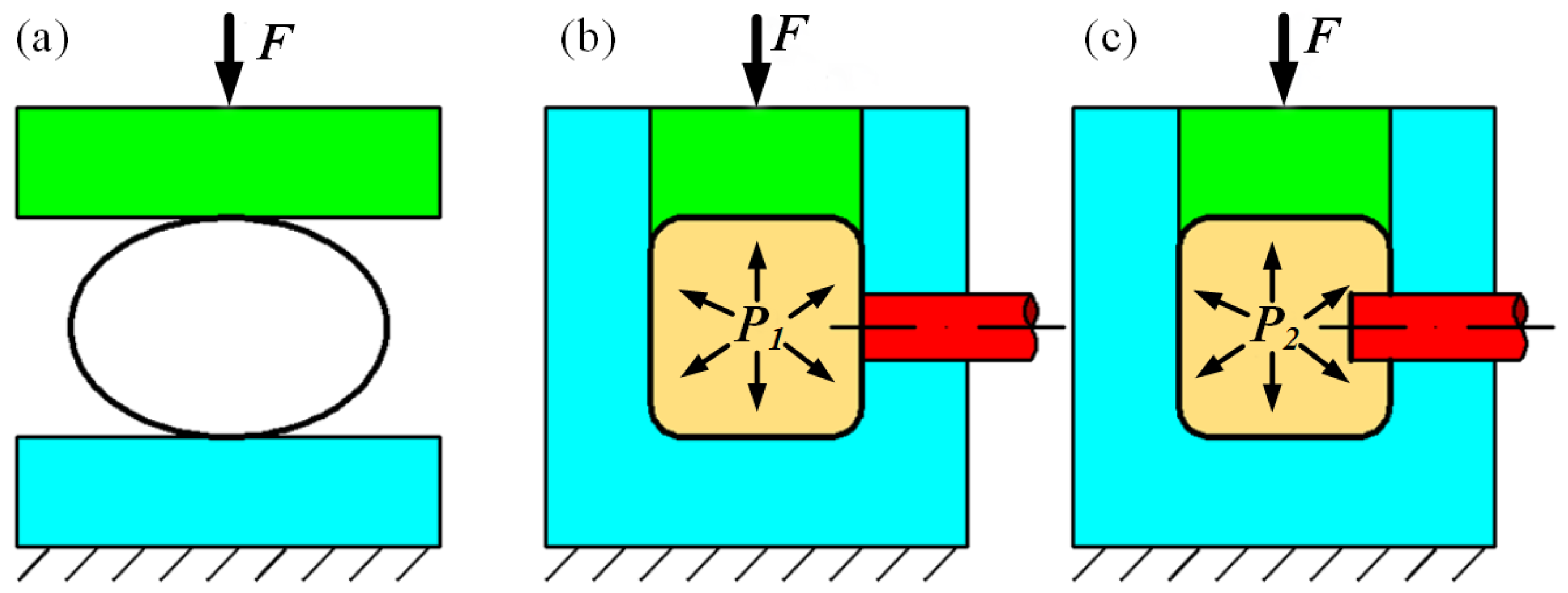
2. Principle of Square Hole Hydro-Piercing

In the present study, hydro-piercing was combined with the tube hydro-pressing process, and then this process could be divided into three major stages: pre-forming, hydro-pressing, and hydro-piercing. The schematic of square hole hydro-piercing is illustrated in Figure 1. Initially, a tube is flattened to be placed into the die in the pre-forming stage, as depicted in Figure 1a. Then, the tube is sealed and filled with medium. The internal pressure is increased to a set value P1, and after that, the upper die closes and presses the tube into the design cross section, as depicted in Figure 1b. In the hydro-piercing stage, by maintaining the upper die, the punch preinstalled in the die moves forward to pierce the tube material after increasing the internal pressure to the design value P2, as shown in Figure 1c. When completed, the punch is moved back and the closing die is opened, and then, the addition of a square hole to the required part can be achieved.

3. Experimental Scheme and Modeling Details

3.1. Materials

A DP600 dual-phase steel tube was employed as the experimental material. The outer diameter of the tube was 50 mm, the thickness was 1.2 mm, and the total length of the tube used in this study was 310 mm. Figure 2 shows the shapes and dimensions of the tube parts in different stages. In the hydro-pressing stage, the cross-sectional shape of the tube changed to a square section, and the length of the straight side of the square section was 44 mm and the corner radius was 10 mm, based on a condition of equal section perimeters. In the hydro-pressing stage, the cross-sectional shape of the tube stayed the same and the square hole with a side length of 10 mm was punched on only one face of the tube.
During the hydro-pressing process, the mechanical properties of the tube changed due to the work hardening. In order to obtain the mechanical properties of the tube after hydro-pressing, uniaxial tensile tests were carried out at room temperature. According to the GB/T228-2010, the tensile samples were cut from the tube along the axial direction and the uniaxial tensile tests were carried out on the Instron-2382 testing machine with an average strain rate of 0.006 s−1. The true stress–strain curve is shown in Figure 3, and the mechanical properties of the tube are listed in Table 1.

3.2. Experimental Procedure

In accordance with the square hole hydro-piercing process, an experimental setup was developed and manufactured that consisted of a hydro-forging press with a capacity of 2000 kN for die closing, control system, and die set, as shown in Figure 4. A hydraulic cylinder of 200 kN was used to provide the driving force of the punch in the process, and the punch speed could be adjusted between 0.1 mm/s and 25 mm/s by controlling the opening size of the oil inlet valve. In the experiment, the speed of the punch was 20 mm/s. Meanwhile, a 100 MPa hydraulic system equipped with a pressure sensor with a precision of 0.25 MPa was used to provide the internal pressure of the tube inside. The press, punch speed, and internal pressure were controlled by a close-hoop servo system.
The die set included an upper die, lower die, piercing device, and sealing device, as shown in Figure 4b. The upper die was connected with the upper movable plate of the press through the upper base plate, and the lower die with the corresponding punch guide hole was mounted on the lower base plate. The materials of the upper die and lower die were both 45# steel. An additional sealing device was used to seal the tube end. Figure 5 provides the assembly diagram of the piercing device, which was composed of a punch, punch set, spring, and knockout plate. The punch was connected with the punch set by thread, and the punch set was connected to the knockout plate by thread. In hydro-piercing, the hydraulic cylinder would push the punch through the knockout plate to complete the punching action. Moreover, a spring was installed between the knockout plate and the lower die to facilitate the return of the punch after hydro-piercing. Due to the removable nature of the punch, the size and shape of the hole could be changed by changing the punch. To analyze the deformation behavior in the square hole hydro-piercing process, square punches with different corner radii were designed in which the punch corner radii R were 0 mm, 1 mm, 2 mm, and 3 mm, as shown in Figure 5. The material of the punches were a kind of cold work die: steel SKD11. The lengths of the punches and punch sets were 60 mm, and the whole assembly length of the piercing device was 140 mm.
For the hydro-pressing stage, Xie et al. [30] have provided the calculation formulas for hydro-pressing process parameters. Therefore, this stage was not investigated in detail in this study, and the internal pressure applied in the experiments was 10 MPa, according to the investigations of the Xie et al.’s study. In our investigation, the effect of internal pressure applied in the hydro-piercing stage on forming and collapse was analyzed specifically, and the tested internal pressure values were 10 MPa, 20 MPa, 30 MPa, 40 MPa, 50 MPa, and 60 MPa.

3.3. Finite Element Model

In order to investigate the material deformation behavior and the stress state in the square hole hydro-piercing process, a numerical analysis was conducted by using ABAQUS/Explicit 6.13. In the simulation, without considering the influence of the pre-forming stage and hydro-pressing stage, the square tube after hydro-pressing was directly used for hydro-piercing simulation. A one-fourth finite element model was established due to the noted symmetry as shown in Figure 6. The die and the punch were assigned to be discrete rigid shells. The tube was modeled by 3D stress solid element C3D8R (an 8-node linear brick with reduced integration and hourglass control). Moreover, an ALE adaptive mesh division was set in the fracture region, and grid element deletion was set. When the element strain reached the fracture strain, the fracture was indicated by deleting the element. The applied mesh is shown in Figure 6, as is the mesh refinement for the straight sidewall deformation region, in order to accurately describe the features of the hole. The maximum mesh size was 0.5 mm in the rounded corner region, the mesh size in the refinement deformation region was 0.1 mm, and the tube was divided into six elements assigned in the direction of the thickness.
The Mises isotropic yield function and the elastic-plastic material model were adopted in these simulations. In this study, the ductile damage failure model was adopted due to the ductile material of DP600 steel, and the initial damage criterion, damage evolution parameters, and unit deletion had to be set in the model. In the hydro-piercing process, the resulting deformation is mainly shear deformation, and thus, the ductile damage criterion and shear damage criterion were used as the initial damage criteria in this study. The ductile damage and shear damage data used as the damage parameters in the model were based on what was standard in the literature [29]. A penalty-based contact algorithm was used to model the contact between the tube, the die, and the punch. The contact between the tube and the die surface was defined as surface-to-surface contact and the friction was modeled as Coulomb friction with μ = 0.1 in the simulations [29]. The internal pressures and the shapes of the punches were consistent with the experiments as described above.

4. Results and Discussion

4.1. Deformation Sequence Analysis

Figure 7 shows the deformed tubes achieved from different forming stages, and for these, the internal pressures used in hydro-pressing and hydro-piercing were 10 MPa and 40 MPa, respectively, and the punch corner radius used in hydro-piercing was 3 mm. It can be seen in the figure that a part with a square hole can be obtained, indicating that the process developed in this work is feasible. As described in Section 3.2, the parameters used in the hydro-pressing stage are fixed. Therefore, only the plastic deformation behavior and the effects of different parameters on the collapse around the hole during the hydro-piercing stage are discussed in detail in the following section.
Based on the previous research [9], it can be known that in circular hole hydro-piercing, the stress state and deformation are the same at all points around the hole because of its centrosymmetric state. However, in square hole hydro-piercing, the stress state around the square hole has no symmetry in the circumferential direction while the force state is similar. Depending on the geometric features of a square hole, the deformation area can be divided into four regions along axial and circumferential symmetry lines. Therefore, a quarter model was selected for research in the current context due to the same stress state at the symmetry points, wherein point A was the vertex of the square hole and the points B and C were the midpoints of the square hole, as shown in Figure 8. During the hydro-piercing, a stress concentration first occurred at point A, when the punch made contact with the tube, as shown in Figure 8a. This illustrated that at point A it would be easy to satisfy the yielding and fracture criteria, and thus, the plastic deformation and crack would occur first. With the movement of the punch, the crack expanded to the points B and C of the square hole, as shown in Figure 8b, until the blank under the punch was completely broken and separated from the tube. Thus, the deformation and fracture sequence developed along paths A → B and A → C. The results indicated that the deformation behavior in the square hole hydro-piercing was quite different from that in the circular hole hydro-piercing. The deformation and fracture processes at each point around the hole were synchronous when the circular hole was punched, while they were not synchronous when the square hole was punched.

4.2. Effect of Internal Pressure on Collapse around the Hole

In the hydro-piercing process, the internal pressured fluid is used as the supporting medium instead of a rigid die. When the internal pressure of the support in the tube is insufficient, a collapse defect is easy formed around the hole after punching, as shown in Figure 9. For convenience in analyzing the collapse behavior of a square hole in the hydro-piercing stage, the degree of the collapse is characterized by collapse depth h and collapse width r, where h is the distance between the bottom end of the fracture and the upper plane of the tube and the r is the distance between the center of the hole and the boundary of the deformation area. As analyzed in Section 4.1, the deformation and fracture processes at each point around the hole were not synchronous. Therefore, the collapse of points A, B, and C, in which the collapse depths and collapse widths were represented as hA, hB, hC and rA, rB, rC, respectively, are discussed in this paper.
Figure 10 shows the experimental results and the corresponding collapse width values at three points obtained under different internal pressures, wherein the punch corner radius was 3 mm. In Figure 10, it can be noted that the collapse width values at three points are basically the same when the internal pressure P is 10 MPa, while the collapse widths rA, rB, and rC are decreased to 11.3 mm, 10.3 mm, and 10.1 mm, respectively, when the internal pressure P increases to 60 MPa. This means that the internal pressure has a significant effect on the collapse, and that the collapse area around a hole decreases with an increase in internal pressure. Meanwhile, the variety trends of the collapse widths at the three points are different. The decreasing trend of point A is less than that of the other two points, meaning that the characteristics of a collapse area gradually change from a round to a square shape as internal pressure increases.
Figure 11 shows the experimental results of the cross section of the tube and the corresponding collapse depth values at three points obtained under different internal pressures wherein the punch corner radius was 3 mm. As can be seen in Figure 11a, the collapse has a great effect on the shape accuracy of the tube when the internal pressure is low. When the internal pressure P is 10 MPa, the collapse area is large and affects the corner region of the tube, reducing the corner radius and changing the shape of the cross section of the tube after hydro-pressing. When the internal pressure increases to 40 MPa, the collapse area decreases and a horizontal straight edge appears in the cross section of the tube around the square hole. When the internal pressure is increased to 60 MPa, the collapse area around the hole is further reduced. This means that the influence of hydro-piercing stage on the shape of the cross section can be reduced by increasing the internal pressure.
The corresponding collapse depth values at three points under different internal pressure are shown in Figure 11b. When the internal pressure P is 10 MPa, the collapse depths hA, hB, and hC are 4.4 mm, 5.2 mm, and 4.6 mm, respectively, meaning that the degrees of collapse at the three points are different when the internal pressure is insufficient. As mentioned above, point A will first experience plastic deformation and crack. When the crack occurs, the material near point A will no longer be directly impacted by the punch and the trend of further collapse at this area will decrease with the movement of the punch, and thus, the collapse depth at point A will be less than those at points B and C. For points B and C, the different collapse depths will be affected by the shapes of their respective sections. During the hydro-piercing, the forces at points B and C will be the same, but the deformation at point B will be affected by the corner area of the cross section, resulting in the collapse depth at point B being larger than that at point C.
However, as the internal pressure increases, the differences between the collapse depths at the three points decrease, and the collapse depths are reduced to 1.5 mm, 1.6 mm, and 1.6 mm when the internal pressure increases to 60 MPa. These results mean that the internal pressure has an obvious effect on the collapse depth around a hole. In the hydro-piercing stage, the increase in internal pressure is equivalent to the increase in the blank-holding force in the stamping process, and since the movement of the material along the punch direction decreases, the collapse depths decrease. Meanwhile, when the internal pressure is high, the collapse area around the hole is reduced and the deformation at point B will be not affected by the corner area, and thus, the collapse depths at point B and point C will be almost the same, indicating that increasing the internal pressure can not only reduce the collapse depth of a point before fracture, but also improve the uniformity of deformation.
Figure 12 shows the Mises stress distribution around a hole under different internal pressures. In this paper, it is assumed that the area where equivalent stress is greater than 430 MPa satisfies the yield condition and experiences plastic deformation because the yield strength of the tube used in the experiment was 430 MPa, and this was taken as the plastic deformation area around the hole after hydro-piercing; the representation method was similar to the one depicted in Figure 9. By comparing Figure 12 with Figure 10, it can be found that the overall variation trend of the simulation was consistent with that of the experiment, meaning that stress distribution has a significant dependence on internal pressure. As shown in Figure 12a, when the internal pressure P is 10 MPa, the collapse widths rA, rB, and rC are 21.6 mm, 21.4 mm, and 21.5 mm, respectively, while the collapse widths rA, rB, and rC are decreased to 11.8 mm, 10.6 mm, and 10.5 mm when the internal pressure increases to 60 MPa. With increasing internal pressure, the range involved in the plastic deformation of the tube is reduced and the shape of the deformation zone gradually changes from round to square, meaning that the degree of concaveness before fracture is decreased. As a result, the degree of collapse under low internal pressure is larger than that under high internal pressure, and this can be attributed to the above characteristics of the Mises stress distribution.

4.3. Effect of Punch Corner Radius on the Collapse around the Hole

Figure 13 shows the experimental results of the hydro-piercing tube obtained under different punch corner radii where the internal pressure was 40 MPa, and the corresponding collapse depth and width values at three points, as obtained from the experiment, are shown in Figure 14. It can be observed from Figure 13 and Figure 14a that the punch corner radius has little effect on the collapse widths at points B and C, but only has an effect on the collapse width at point A of the square hole. With an increase in the punch corner radius, the collapse width at point A decreases, meaning that the collapse area around the hole tend to be round and conducive to the coordination of material deformation around the hole.
Furthermore, it also can be found from Figure 14b that the collapse depth value of point A (hA) increases slowly with an increasing punch corner radius, while the collapse depth values of points B and C (hB and hC) show no obvious changes. This means that the corner radius has little effect on the collapse depths of points B and C, and that the change of the punch corner radius only causes the change of the collapse of the corner area of the square hole. As analyzed in Section 4.1, it will be easy for point A to satisfy the yielding and fracture criteria. Then, the crack expands to the points B and C of the square hole. When the punch corner radius increases, the area of the stress concentration becomes larger and gradually moves to point B and point C, leading to a uniform deformation at the three points, and thus, the collapse depth value of point A will gradually become consistent with those of the other two points.
The Mises stress distribution around the hole with different punch corner radii is shown in Figure 15. By comparing Figure 15 with Figure 14a, it can be found that when the punch corner radius is 0 mm, the shape of the deformation zone around the hole is close to a square shape, while it gradually tends to be circular when the punch corner radius is from 0–3 mm. However, the range of the deformation zone changes little as the punch corner radius increases. This indicates that a change in punch corner radius only influences the deformation of the corner area of a square hole, and has little effect on the other areas. In other words, when the corner radius increases, the deformation zone around the square hole also becomes gradually rounded, and the stress distribution around the hole becomes more uniform.

5. Conclusions

In the present work, the material deformation and fracture mechanism of a square hole in the tube hydro-piercing process was analyzed and the effects of internal pressure and punch corner radius on the collapse around the hole were investigated using a finite element simulation and experiment. The following are the conclusions from the present work:
  • In the square hole hydro-piercing process, a stress concentration occurs at the vertex of the square hole, making it easy to satisfy the yielding and fracture criteria, and then the crack expands to the midpoints of the square hole with the movement of the punch, implying that the deformations and fractures at different positions are asynchronous.
  • When the internal pressure is insufficient, the collapse depths at different positions are obviously different. However, the collapse depths of the midpoints of the square hole will be almost the same when internal pressure increases to 60 MPa, meaning that increasing the internal pressure can improve the uniformity of deformation.
  • With the increasing of internal pressure, the degree of collapse can be decreased. When the internal pressure increases from 10 MPa to 60 MPa, the collapse depth values hA, hB, hC decrease to 1.5 mm, 1.6 mm, and 1.6 mm, respectively, from 4.4 mm, 5.2 mm, and 4.6 mm, respectively. Additionally, punch corner radius has little effect on the collapse around the hole.

Author Contributions

Methodology, Z.F. and Q.W.; investigation and experimentation, X.W.; writing—original draft, L.S.; writing—review and editing, C.L. and X.L.; conceptualization and funding acquisition, G.C. All authors have read and agreed to the published version of the manuscript.

Funding

This study was financially supported by the National Natural Science Foundation of China (Grant No. U1937205 and No. 52275319) and Key Research and Development Program of Shandong Province (Grant No. 2020CXGC010303 and No. 2022JMRH0302).

Institutional Review Board Statement

Not applicable.

Informed Consent Statement

Not applicable.

Data Availability Statement

The datasets used or analyzed during the current study are available from the corresponding author on reasonable request.

Conflicts of Interest

The authors declare no conflict of interest.

References

  1. Nikhare, C.; Weiss, M.; Hodgson, P.D. Die closing force in low pressure tube hydroforming. J. Mater. Process. Technol. 2010, 210, 2238–2244. [Google Scholar] [CrossRef]
  2. Zhang, X.L.; He, J.Q.; Chu, G.N.; Yuan, S.J. Experimental research on deformation and dimensional accuracy of rectangular-section tubular part during open die hydro-pressing process. Proc. Inst. Mech. Eng. Part B J. Eng. Manuf. 2021, 235, 705–714. [Google Scholar] [CrossRef]
  3. Han, C.; Zhuang, Y.P.; Li, J. Thickness distribution uniformity improvement and forming pressure reduction of stepped tubular components by axial hydro-pressing method. Int. J. Adv. Manuf. Technol. 2022, 121, 2615–2630. [Google Scholar] [CrossRef]
  4. Yamashita, M.; Mori, T.; Nikawa, M. Hole Making Process of Metal and Composite Sheets by Impact Hydraulic Pressure. Proc. Eng. 2017, 207, 1558–1563. [Google Scholar] [CrossRef]
  5. Aravind, U.; Chakkingal, U.; Venugopal, P. A review of fine blanking: Influence of die design and process parameters on edge quality. J. Mater. Eng. Perform. 2021, 30, 1–32. [Google Scholar] [CrossRef]
  6. Finckenstein, E.V.; K. Kleiner, M.; Szücs, E.; Homberg, W. In-process punching with pressure fluids in sheet metal forming. CIRP Ann. Manuf. Technol. 1998, 47, 207–212. [Google Scholar] [CrossRef]
  7. Koc, M.; Altan, T. Prediction of Forming Limits and Parameters in the Tube Hydroforming Process. Int. J. Mach. Tool. Manuf. 2002, 42, 123–138. [Google Scholar] [CrossRef]
  8. Yamashita, M.; Sugiure, K.; Nikawa, M. Punchless piercing process of aluminum tube wall by impulsive water pressure. Mater. Trans. 2023, 6, 414–420. [Google Scholar] [CrossRef]
  9. Choi, S.K.; Kim, W.T.; Moon, Y.H. Analysis of deformation surrounding a hole produced by tube hydro-piercing. Proc. Inst. Mech. Eng. Part B J. Eng. Manuf. 2004, 218, 1091–1097. [Google Scholar] [CrossRef]
  10. Su, H.B.; Liu, G.; Chen, X.P.; Qi, J. Influence of hydro-pressure inside tube on hydropiercing. Forg. Stamp. Technol. 2011, 36, 19–22. [Google Scholar]
  11. Su, H.B.; Liu, G.; Chen, X.P. Simulation analysis and experimental research on hydro-piercing. J. Net. Form. Eng. 2017, 9, 73–78. [Google Scholar]
  12. Manabe, K.; Amino, M.; Nakamura, S. FE Analysis on Local Thinning and Fracture Phenomenon in Hydroform of Tube Components. Adv. Technol. Plast. 1999, 1, 12–21. [Google Scholar]
  13. Manabe, K.; Amino, M. Effects of Process Parameters and Material Properties on Deformation Process in Tube Hydroforming. J. Mater. Process. Technol. 2002, 12, 285–291. [Google Scholar] [CrossRef]
  14. Hwang, Y.M.; Wu, R.K. Process and loading path design for hydraulic compound forming of rectangular tubes. Int. J. Adv. Manuf. Technol. 2017, 91, 2135–2142. [Google Scholar] [CrossRef]
  15. Kim, S.S.; Han, C.S.; Lee, Y.S. Development of a new burr-free hydro-mechanical punching. J. Mater. Process. Technol. 2005, 162, 524–529. [Google Scholar] [CrossRef]
  16. Liu, G.; Lin, J.F.; Wand, G.; Su, H.B.; Chen, X.P.; Jiang, H.M. Influence of tube properties on quality of hydropiercing. Trans. Nonferrous Met. Soc. China 2012, 21, 456–460. [Google Scholar] [CrossRef]
  17. Yang, T.; Hao, J.; Liu, G. Influence of Punch Shape on the Fracture Surface Quality of Hydropiercing Holes. J. Harbin. Inst. Technol. 2014, 3, 85–90. [Google Scholar]
  18. Shiomi, M.; Ueda, Y.; Osakada, K. Piercing of Steel Sheet by using Hydrostatic Pressure. CIRP Ann. Manuf. Technol. 2006, 55, 255–258. [Google Scholar] [CrossRef]
  19. Hwang, Y.M.; Dai, W.H.; Chen, C.C. Investigation of punch shape design in tube hydro-piercing processes. Int. J. Adv. Manuf. Technol. 2020, 110, 2211–2220. [Google Scholar] [CrossRef]
  20. Liu, Z.Y.; Li, F.; Shi, W.Y.; Li, X.W.; Fang, W.B. Research on piercing of aluminum sheet assisted with magnetic medium. Int. J. Adv. Manuf. Technol. 2019, 104, 4735–4744. [Google Scholar] [CrossRef]
  21. Liu, Z.Y.; Li, F.; Mu, Y.Y.; Xu, J. Comprehensive evaluation of process parameters optimization for sheet piercing assisted by magnetic medium based on grey relational analysis. Results Phys. 2020, 19, 103288. [Google Scholar] [CrossRef]
  22. Wang, P.Y.; Wan, G.H.; Jin, J.G.; Wang, Y.C.; Xiang, N.; Zhao, X.K.; Zhao, X.N.; Yuan, B.X.; Wang, Z.J. Subregional flexible-die control in magnetorheological pressure forming. J. Mater. Process. Technol. 2022, 307, 117698. [Google Scholar] [CrossRef]
  23. Hwang, Y.M.; Phan, H.N.; Tsui, H.S.R. Investigation of Punch Shape and Loading Path Design in Hydro-Flanging Processes of Aluminum Alloy Tubes. Metals 2021, 11, 636. [Google Scholar] [CrossRef]
  24. Liu, W.; Hao, J.; Liu, G.; Gao, G.; Yuan, S. Influence of punch shape on geometrical profile and quality of hole piercing-flanging under high pressure. Int. J. Adv. Manuf. Technol. 2016, 86, 1253–1262. [Google Scholar] [CrossRef]
  25. Kumar, S.; Ahmed, M.; Panthi, S.K. Effect of Punch Profile on Deformation Behaviour of AA5052 Sheet in Stretch Flanging Process. Arch. Civil Mech. Eng. 2020, 20, 1–17. [Google Scholar] [CrossRef] [Green Version]
  26. Yu, X.Y.; Chen, J.; Chen, J.S. Interaction Effect of Cracks and Anisotropic Influence on Degradation of Edge Stretchability in Hole-expansion of Advanced High Strength Steel. Int. J. Mech. Sci. 2016, 105, 348–359. [Google Scholar] [CrossRef]
  27. Dixit, U.S.; Joshi, S.N.; Davim, J.P. Incorporation of material behavior in modeling of metal forming and machining processes: A review. Mater. Des. 2011, 32, 3655–3670. [Google Scholar] [CrossRef]
  28. Yildiz, R.A. Numerical analysis of the damage evolution of DP600 steel using Gurson-Tvergaard-Needleman model. Steel. Res. Int. 2023, 94, 2200147. [Google Scholar] [CrossRef]
  29. Hassannejadasl, A.; Green, D.E.; Altenhof, W.J.; Maris, C.; Mason, M. Numerical modeling of multi-stage tube hydropiercing. Mater. Des. 2013, 46, 235–246. [Google Scholar] [CrossRef]
  30. Xie, W.C.; Han, C.; Chu, G.N.; Yuan, S.J. Research on hydro-pressing process of closed section tubular parts. Int. J. Adv. Manuf. Technol. 2015, 80, 1149–1157. [Google Scholar] [CrossRef]
Figure 1. Schematic illustration of square hole hydro-piercing. (a) Pre-forming, (b) hydro-pressing, and (c) hydro-piercing.
Metals 13 01107 g001
Figure 2. Shape and dimensions of the part.
Metals 13 01107 g002
Figure 3. Flow stress curve of the DP600 steel tube.
Metals 13 01107 g003
Figure 4. Experimental equipment: (a) hydroforming press; (b) experimental die.
Metals 13 01107 g004
Figure 5. Diagram and dimensions of the piercing device.
Metals 13 01107 g005
Figure 6. Finite element model.
Metals 13 01107 g006
Figure 7. Deformed tubes under different stages.
Metals 13 01107 g007
Figure 8. The deformation sequence of square hole hydro-piercing. (a) Stress concentration at point A; (b) crack extends to points B and C.
Metals 13 01107 g008
Figure 9. The collapse after square hole hydro-piercing.
Metals 13 01107 g009
Figure 10. Effect of internal pressure on collapse width. (a) Experiment results; (b) collapse width.
Metals 13 01107 g010
Figure 11. Effect of internal pressure on collapse depth. (a) Experiment results; (b) collapse depth.
Metals 13 01107 g011
Figure 12. Mises stress distribution around the hole under different internal pressure (a) 10 MPa, (b) 30 MPa, (c) 50 MPa, (d) 60 MPa.
Metals 13 01107 g012
Figure 13. Experiment results with different punch corner radii: (a) R = 0 mm, (b) R = 1 mm, (c) R = 2 mm, and (d) R = 3 mm.
Metals 13 01107 g013
Figure 14. Effect of punch corner radius on collapse around the hole. (a) collapse width, (b) collapse depth.
Metals 13 01107 g014
Figure 15. Mises stress distribution around the hole with different corner radii: (a) R = 0 mm, (b) R = 1 mm, (c) R = 2 mm, and (d) R = 3 mm.
Metals 13 01107 g015
Table 1. Mechanical parameters of the DP600 steel tube.
Mechanical ParametersValue
Yield stress, σs (MPa)430
Ultimate tensile strength, σb (MPa)750
Total elongation, δ (%)23
Young’s modulus, E (GPa)195
Poission’s ratio, ν0.3
Strength coefficient, K (MPa)982
Strain hardening exponent, n0.158
Disclaimer/Publisher’s Note: The statements, opinions and data contained in all publications are solely those of the individual author(s) and contributor(s) and not of MDPI and/or the editor(s). MDPI and/or the editor(s) disclaim responsibility for any injury to people or property resulting from any ideas, methods, instructions or products referred to in the content.

