Article

Efficiently Removing Hydrogen of H-Supersaturated Liquid Steel in the Vacuum Degasser with Various Gas Injection Modes

1
Anhui Province Key Laboratory of Metallurgical Engineering & Resources Recycling (Anhui University of Technology), Maanshan 243002, China
2
School of Metallurgy, Northeastern University, Shenyang 110819, China
3
CSSC Sunrui (Luoyang) Special Equipment Co., Ltd., Luoyang 471000, China
*
Authors to whom correspondence should be addressed.
Metals 2023, 13(7), 1229; https://doi.org/10.3390/met13071229
Submission received: 5 June 2023 / Revised: 28 June 2023 / Accepted: 29 June 2023 / Published: 3 July 2023
(This article belongs to the Special Issue Advanced Tundish Metallurgy and Clean Steel Technology)

Abstract

:
Hydrogen removal of H-supersaturated liquid steel produced in a hydrogen-rich environment in an industrial vacuum degasser (VD) is simulated here using a two-phase (argon–steel) Eulerian model. The dehydrogenation efficiency is evaluated for a series of ladle plug layouts and argon-purging modes. Increasing the plug number from the prototype double-plug of the ladle to four or slightly prolonging the degassing time of a triple-plug ladle enables to obtain the specified dehydrogenation efficiency and the end-point hydrogen level. Varying the plug position of the triple-plug ladle makes no significant difference in the dehydrogenation efficiency, which, however, is improved by adjusting the plug angle. For the triple-plug ladle, the non-uniform argon-purging mode improves the melt hydrodynamic conditions, but the optimal dehydrogenation performance is achieved in the uniform mode. The plug number has the greatest impact on the dehydrogenation efficiency compared to the other ladle designs considered. The high-efficiency dehydrogenation of H-supersaturated liquid steel in the VD can be achieved through using the quadruple plugs, or by using the triple plugs positioned at 0.57R, 0.57R, and 0.41R and the angles of 108.6° and 71.4°, with the uniform argon-purging flow rate.

1. Introduction

Producing liquid iron/steel in an H-rich environment, such as hydrogen gas or hydrogen plasma, is known as one of the promising alternatives to conventional iron–steel-making processes to reduce CO2 emissions in the steel industry and has received worldwide attention [1,2,3,4,5]. In this process, the molten iron oxide is reduced to liquid iron/steel by hydrogen, with the superiority of CO2-free emissions and an almost pure metal product available. However, in this process, simultaneously, the hydrogen easily dissolves in the produced liquid iron/steel due to the H-rich environment and the elevated temperature, and as a result, an overly high hydrogen content in the liquid iron/steel can be generated. As is well-known, hydrogen can deteriorate the mechanical properties of steel due to the formation of flakes, the occurrence of breakouts, and hydrogen embrittlement [6,7].
Therefore, it is essential to first estimate the possible hydrogen content in the liquid iron/steel produced in the H-rich environment based on the thermodynamics. In a hydrogen gas environment, the dissolution of the hydrogen gas into liquid iron/steel is as follows:
1 2 H 2 = [ H ] ,
and according to the Sievert’s law, the solubility of atomized hydrogen in liquid iron/steel is as follows [8]:
[ % H ] e = K H 2 f H P H 2 ,   and   lg K H 2 = 1670 T 1.68
where KH2, fH, and P H 2 are the equilibrium constant, the activity coefficient of hydrogen in liquid iron/steel, and the H2 partial pressure, respectively. For simplification, it is assumed possible to ignore the effect of other elements in the liquid iron/steel on the hydrogen activity coefficient, i.e., fH = 1.0, and then the dissolved hydrogen in the liquid iron/steel as a function of the H2 partial pressure at a temperature such as 1600 °C can be plotted, as in Figure 1. It can clearly be seen that, as an example, the hydrogen content in liquid iron/steel reached up to 18.5 ppm and 26.8 ppm when the fraction of the H2 partial pressure was 50% and 100%, respectively, which is much higher than that in the liquid iron/steel produced in the conventional iron–steel-making processes, such as the Basic Oxygen Furnace (BOF) and the Electric Arc Furnace (EAF). Notably, Equation (2) is only true when hydrogen exists only in a molecular state, i.e., H2, whereas the solubility of hydrogen in liquid iron/steel in the hydrogen plasma state is as follows [9]:
[ % H ] e = K H 2 P H 2 + K H P H + K H + ( P H + + P e ) f H
where PH, PH+, and Pe are the partial pressures of atomized hydrogen, ionized hydrogen, and electrons, respectively. KH and KH+ are the equilibrium constants for the dissolution of atomized and ionized hydrogen particles, respectively. Previous studies [4,10] confirmed that the solubility in metals of gases in their plasma state exceeded the equilibrium solubility levels attainable when gases were dissolved from their molecular states due to the lower activation energy for the dissolution of ionized and atomized particles, indicating that the liquid iron/steel produced in the hydrogen plasma environment has a higher hydrogen content than that produced in the H2 environment. Therefore, achieving H-supersaturated liquid iron/steel is quite possible in an H-rich environment.
It is of great concern how the hydrogen can be efficiently removed from the H-supersaturated liquid steel produced in an H-rich environment. In the steel industry, the hydrogen degassing from liquid steel is usually achieved in an exclusive vacuum-degassing apparatus, such as VD or Ruhrstahl-Heraeus (RH), in which liquid steel is subjected to a combination of low pressure and argon-purging, and as a result, the dissolved hydrogen can be considerably reduced. In this direction, a great number of studies [11,12,13,14,15,16,17,18,19,20,21,22,23,24,25,26] have been performed to reveal the dehydrogenation behavior of liquid steel based on the thermodynamics and kinetics related to hydrogen removal in an industrial RH or VD by employing an industrial test or Computational Fluid Dynamics techniques. Steneholm et al. [11] calculated the removal rates of sulfur, hydrogen, and nitrogen by collecting slag and steel samples before and after the vacuum treatment. Zhang et al. [12] developed a mathematical model of an industrial single-snorkel refining furnace to reveal the dehydrogenation behavior in the vacuum refining process, by considering three dehydrogenation reaction sites, including the Ar bubble surface, the bath surface, and the bulk steel. The effect of the argon flow rate on the dehydrogenation rate was studied, and a reasonable range of the argon flow rate for the SSRF treatment was recommended by the authors. Yu et al. [13,14] simulated hydrogen and nitrogen degassing in the vacuum tank degasser by combining a Eulerian–Eulerian, argon–steel, two-fluid model with thermodynamics. Recently, Karouni et al. [15,16] developed a mathematical model accounting for hydrogen degassing in a vacuum arc degasser using a three-phase Eulerian method and a discrete population balance model, and they investigated the effect of plug positions and the ladle aspect ratio on hydrogen removal. More recently, Chen et al. [18,19] numerically studied the tracers’ transport process in a water model of a vacuum refining unit corresponding to a single-snorkel refining furnace, focusing on the fluid dynamics for degassing. Furthermore, some other investigations [20,21,22,23,24,25,26] focused on the hydrodynamics in the ladle and on expounding the effect of purge arrangements. However, the current investigation is more focused on the dehydrogenation of the liquid steel with conventional low hydrogen levels (generally lower than 8 ppm), and it is still not yet clear whether the final hydrogen level in H-supersaturated liquid steel produced in an H-rich environment can be efficiently reduced to a desired level through the routine operation conditions of the vacuum-degassing apparatus. A recent study by Li et al. [27] indicated that efficient removal of hydrogen from H-supersaturated liquid steel was not possible by using the routine operation conditions in the VD unit, unless the argon-purging rate was excessively increased; however, this would cause operation problems such as serious splashing, and thus further steps must be taken to efficiently remove hydrogen from H-supersaturated liquid steel produced in an H-rich environment. Therefore, optimizing the ladle design and process conditions is of prime necessity in ensuring that the hydrogen degassing of H-supersaturated liquid steel is cost-effective.
To this end, a set of ladle designs in terms of the plug number, the radial position of each plug, and the angle between neighboring plugs, and of the argon-purging modes for multi-plug ladles, are numerically evaluated in this study to investigate the effect of the plug layout and the argon-purging mode on hydrogen removal in the VD unit. The aim is to identify the optimal design conditions for achieving the efficient removal of hydrogen from H-supersaturated liquid steel. The velocity field of the liquid steel, the hydrogen-degassing efficiency, and the final hydrogen content in liquid steel are thus compared and contrasted for various case studies. The rest of the paper is composed as follows. First, the mathematical formulation for calculating the coupled multiphase flows and transient dehydrogenation, as well as the solution strategies used for this study, are presented in Section 2. Section 3 presents the simulation results of the influence of the plug layout and the argon-purging mode on the dehydrogenation efficiency. Section 4 summarizes the conclusions of this study.

2. Numerical Model

An integrated mathematical model representing dynamic coupling of Computational Fluid Dynamics and thermodynamics for dehydrogenation in an industrial VD was established to predict the rate of hydrogen removal from H-supersaturated liquid steel. In this model, the slag was neglected, and thus the liquid steel and argon were included. The flow equations for steel and argon were solved using a two-phase Eulerian model by assuming the steel and argon to be incompressible fluids. The density of steel and argon was 7100 kg/m3 and 0.48 kg/m3 at 1600 °C, respectively, and their viscosity was 0.005 Pa s and 8.4 × 10⁻⁵ Pa s, respectively [13]. Liquid steel surface tension was specified as 1.2 N/m. The governing equations for multiphase flow and the turbulence kinetic energy, k, and dissipation energy, ε, expressed by a modified k-ε model [28], are summarized in Table 1.
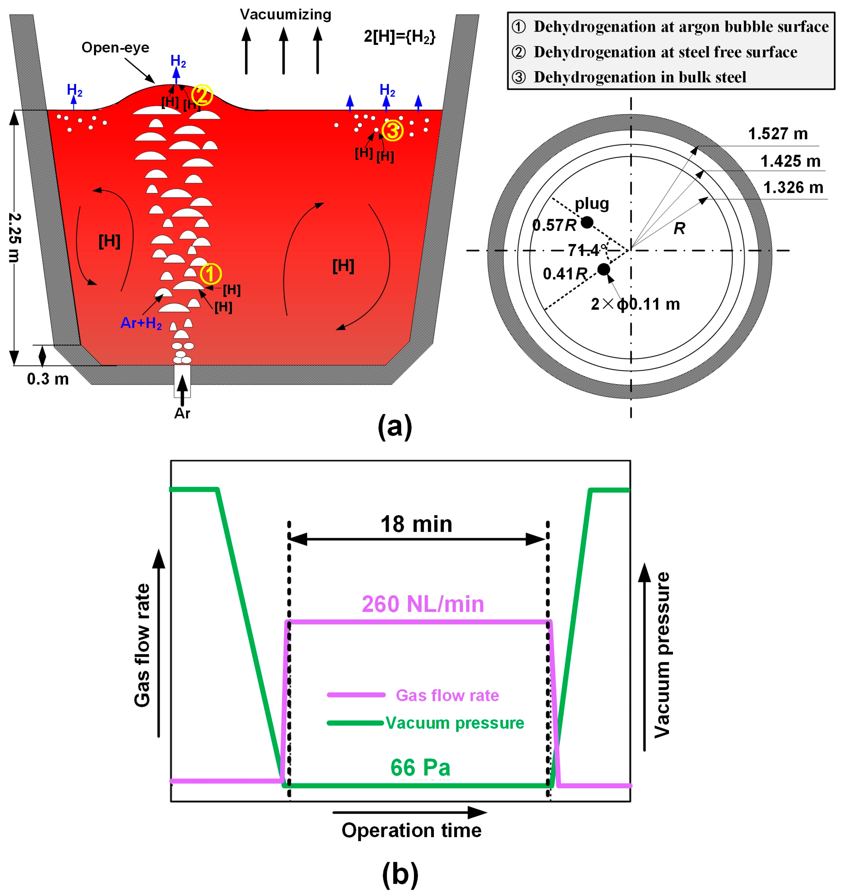
Industrial-scale hydrogen degassing was undertaken in a 105-ton VD unit, which is schematically shown in Figure 2. The ladle dimensions are shown in Figure 2a. For the typical and routine degassing process, the liquid steel in the ladle was subjected to a reduced pressure of 66 Pa and was simultaneously stirred by a total argon-purging flow rate of 260 NL/min, injected from two purges positioned at the ladle bottom, with a diameter of 0.11 m for each purge. The process was held for 18 min for efficient hydrogen removal. In this mathematical model, hydrogen was removed through three routes, i.e., by the rising argon bubbles, the steel-free surface where the open-eye is located, and the bulk steel by nucleation near the bath surface, as shown in Figure 2a. A detailed model description for the dehydrogenation models via the three routes can be found in our recent study [27]. The solubility of atomized hydrogen in liquid steel was given by Sievert’s law [29], as:
[ % H ] eq = K f H P H 2 P Θ ,   and   lg K = 1670 T 1.68
where the hydrogen activity coefficient, fH, in liquid steel was calculated as follows:
log f H = ε H j [ % j ]
where ε H j is the interaction coefficient, which was obtained elsewhere [13].
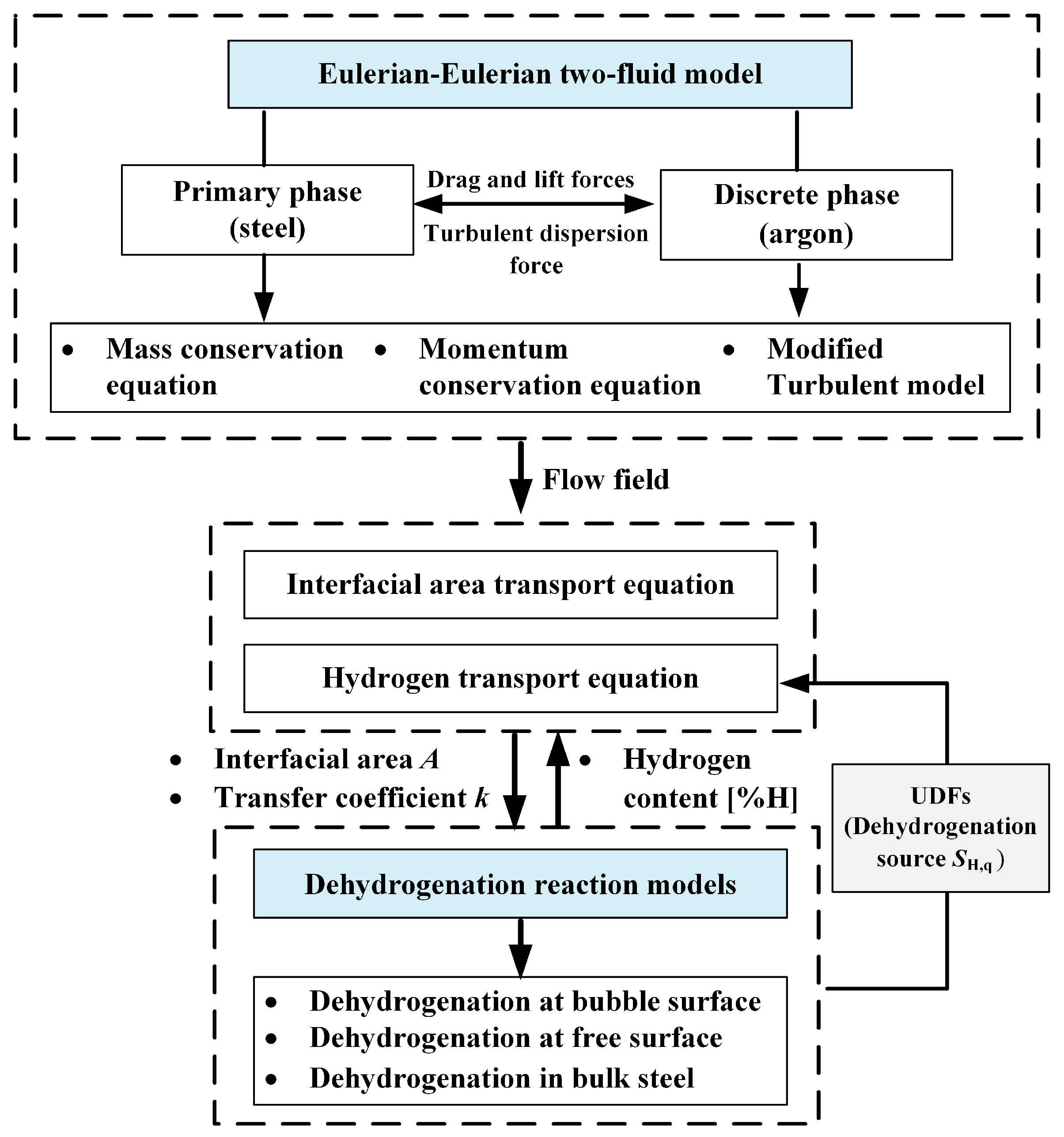
The system of equations was solved by combining the authors’ user-defined subroutines for dehydrogenation with a commercial CFD software (Fluent version 14.5). The flow chart of the mathematical models is presented in Figure 3. Velocity inlet and degassing outlet boundary conditions were specified according to the argon-purging rate. The predictive capability of the present dehydrogenation model in the VD was validated against the measured velocity field and hydrogen content in the VD. Specifically, first, the simulated flow velocity of the gas and liquid by the present two-phase Eulerian model in a scaled-down ladle water model was compared with the measurements. Then, the dehydrogenation models in the VD were verified by comparing the predicted hydrogen content with the data under various operating conditions of the VD. In general, the results predicted by the current model showed reasonable agreement with the experimental data, as detailed in the recent study by the current authors [27].

3. Results

As a potential case study, the initial hydrogen content, [H]initial, in the H-supersaturated liquid steel was assumed to be 27 ppm for all simulations. The routine operation parameters of the total argon-purging rate of 260 NL/min and the reduced pressure of 66 Pa were maintained for all case studies.

3.1. Number of Plugs

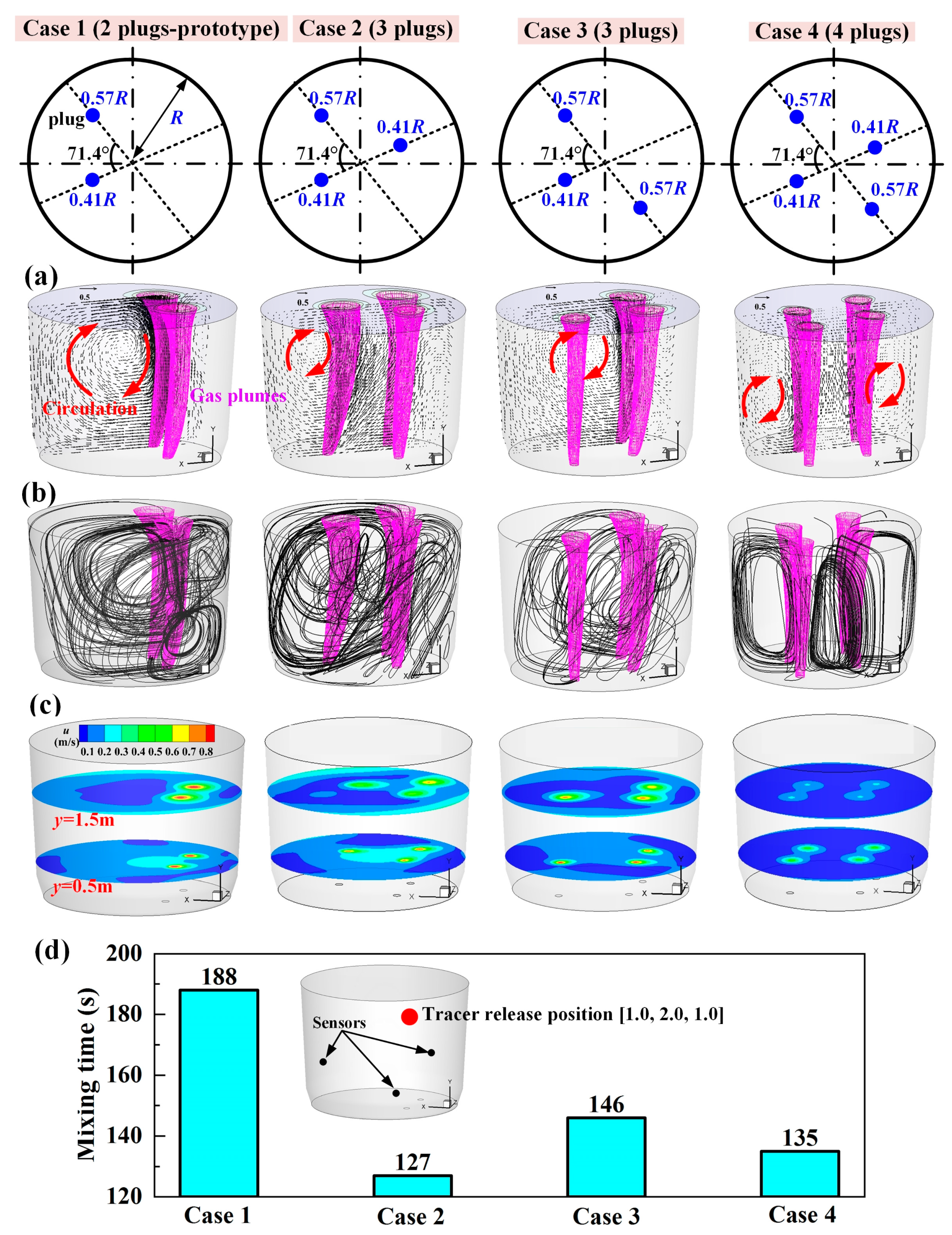
Double-, triple-, and quadruple-plug layouts were considered to investigate the effect of the number of plugs on the hydrogen-degassing performance in the VD. Figure 4 shows the plug number layouts, where case 1 represents the prototype double-plug layout in the VD, while the others (cases 2–4) show the new ladle designs. A prominent feature is that the shape of the argon plumes, and as a result the velocity field of the melt, were changed when increasing the plug number, as shown in Figure 4a. For the double-plug layout (prototype ladle design), the argon plumes tended to bend towards the ladle wall close to the plugs while rising through the melt, and a large circulation developed in the melt region away from the plumes. When increasing the plug number to triple, such a bending tendency of the plumes declined, and the circulation lessened. For the quadruple-plug layout, the plumes attracted each other and bent towards the ladle center due to the symmetrical layout of the plugs, and small circulations developed, surrounding the plumes. As can be seen, the plume width decreased when increasing the plug number due to the reduced argon flow rate injected from each plug. Moreover, a higher argon-purging flow rate from the plug resulted in a higher melt velocity in the argon-melt-mixing region and a steeper melt velocity gradient in the ladle, as shown in Figure 4b,c. Consequently, the different plug number layouts contributed to a diverse mixing efficiency in the ladle, as shown in Figure 4d, where the mixing time calculated by averaging the mixing times monitored at the three sensors is compared between the various plug number layouts. For the prototype double-plug layout, the mixing time was the longest (188 s). Increasing the plug number to triple or quadruple remarkably shortened the mixing time, but the mixing time for the triple- and quadruple-plug layouts was not significantly different. The shortest mixing time (127 s) was obtained with the triple-plug layout of case 2.
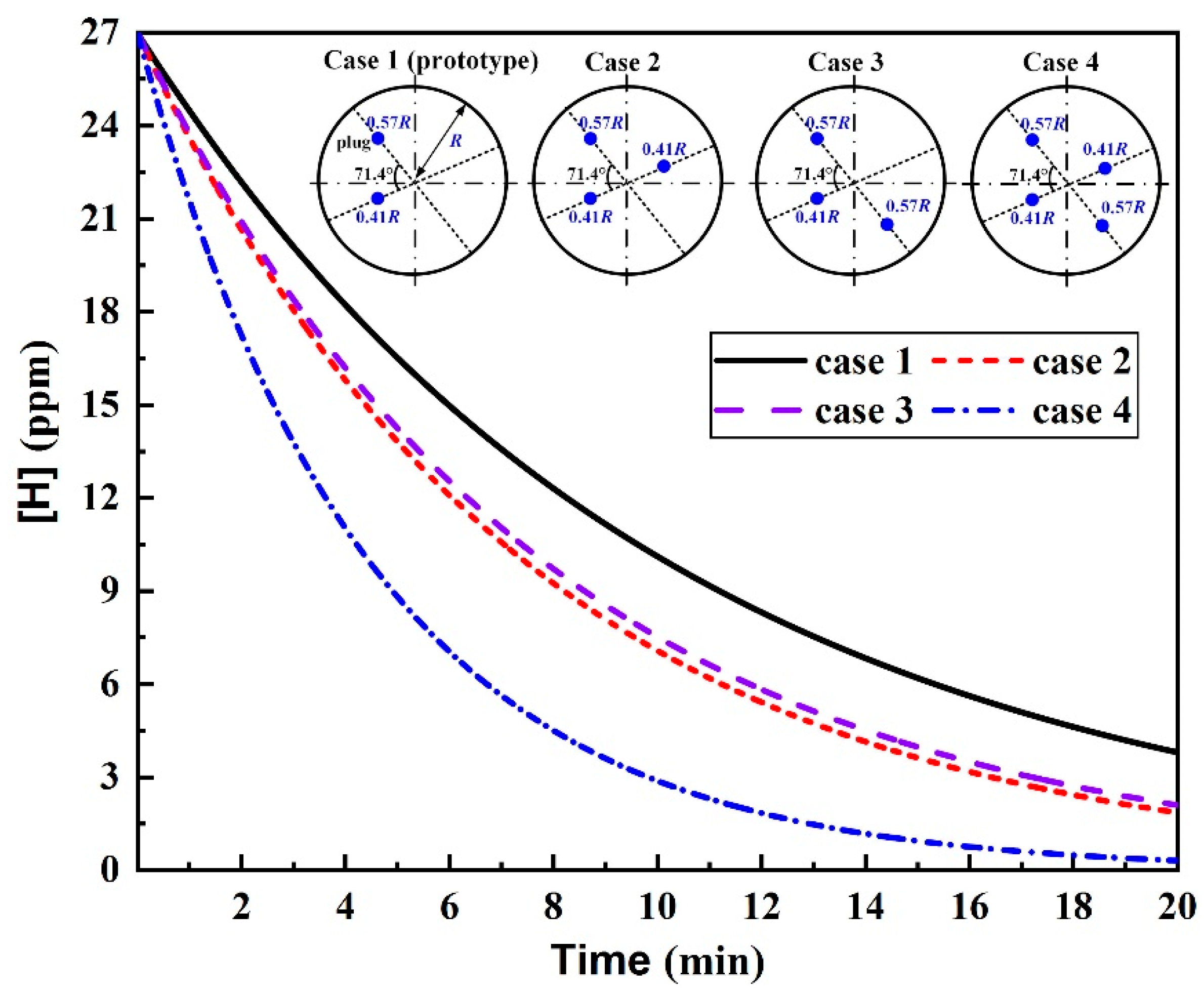
Figure 5 plots the effect of the plug number on the dehydrogenation rate of H-supersaturated liquid steel in the VD. A general feature of all the simulated cases was that the dehydrogenation rate in the early stage (before 10 min of degassing) was high, and then gradually declined. This is a consequence of the high hydrogen level in the early stage, causing a large concentration gradient for mass transfer, while the concentration gradient was small due to the low hydrogen level in the later degassing stage. As can be seen, increasing the plug number improved the dehydrogenation rate and enabled to reduce the dissolved hydrogen level. This could be explained as follows: increasing the plug number increased the number of argon bubbles, which is the primary degassing route in VD, and thus enlarged the bubbles–steel interface area for mass transfer.
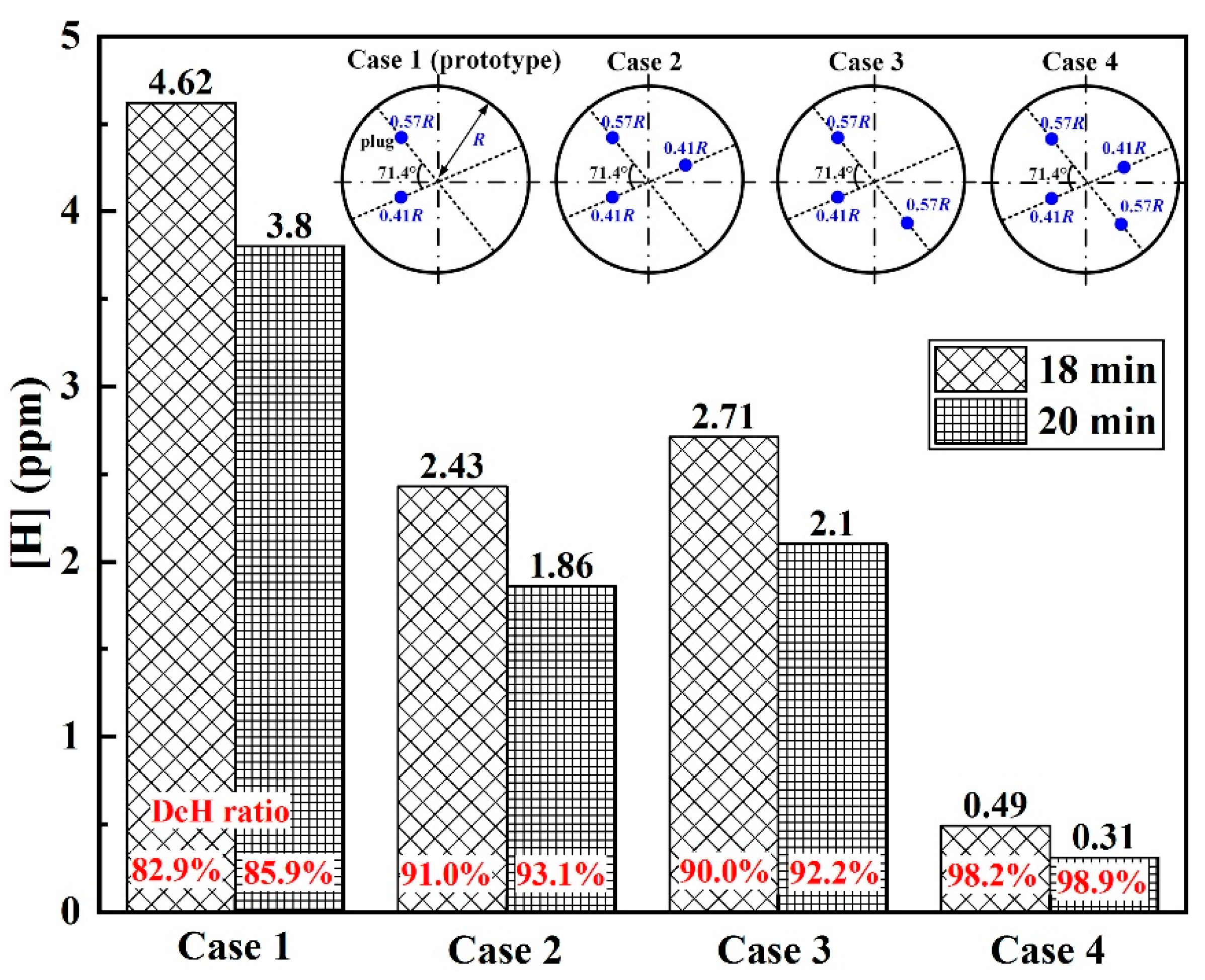
Figure 6 compares the final hydrogen content in liquid steel at the end of degassing between the various plug number layouts. Generally, increasing the plug number enabled to reduce the final hydrogen content and improve the dehydrogenation ratio (DeH ratio) at the end of the degassing. Specifically, at the routine degassing time, i.e., t = 18 min, the final hydrogen content for the prototype double-plug layout was 4.62 ppm, while it was reduced to 0.49 ppm for the quadruple-plug layout, and the corresponding DeH ratio increased from 82.9% to 98.2%. It is clear that at the routine degassing time for the H-supersaturated liquid steel, it was not possible to reduce the final hydrogen content to a desired low level (<2 ppm) by employing the double- and triple-plug layouts, whereas it could be achieved for the quadruple-plug layout, or for the triple-plug layout, under which, however, the degassing time had to be slightly prolonged to 20 min.

3.2. Plug Position

In view of the ability of attaining a prospective dehydrogenation efficiency for the triple-plug layout of case 2, it was necessary to further investigate the various plug arrangements in terms of the plug position and plug angle of the triple-plug layout to identify the optimal design conditions for achieving more efficient hydrogen degassing of H-supersaturated liquid steel in the VD.
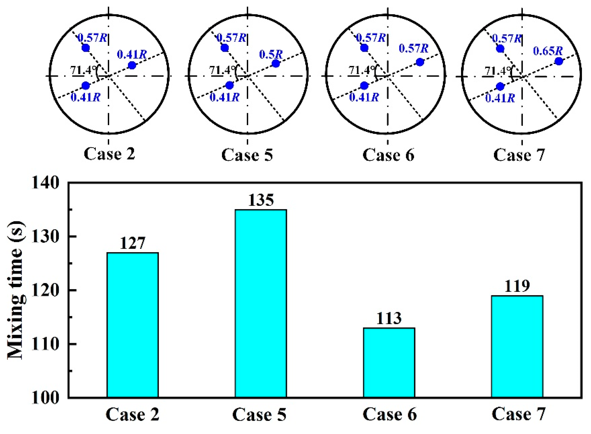
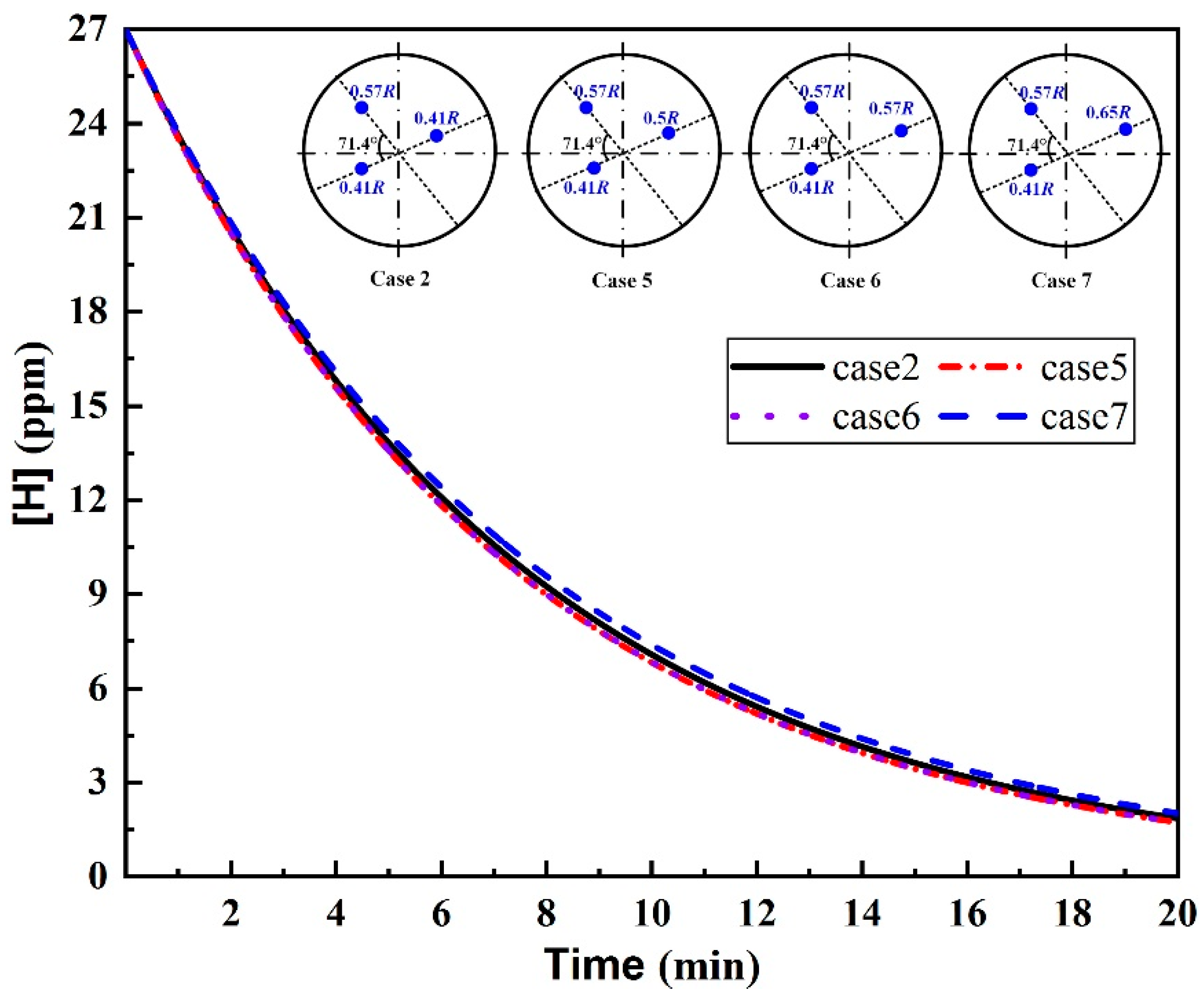
The radial position of the triple-plug layout of case 2 was varied, and the resulting changes in the mixing time are shown in Figure 7. The results indicated that there was no significant difference in the mixing time between all cases, and the shortest mixing time (113 s) was obtained at the plugs’ radial positions of 0.57R, 0.57R, and 0.41R (case 6). The results showed that varying the plug position of the triple-plug layout did not dramatically affect the flow field in the ladle. Figure 8 compares the dehydrogenation efficiency between the various plug positions. As can be seen, the dehydrogenation rate and the final hydrogen level were little affected by the plug position. At 20 min of degassing, the final hydrogen levels for cases 2–7 were 1.86 ppm, 1.73 ppm, 1.73 ppm, and 2.03 ppm. Therefore, the optimal design condition for achieving a more efficient hydrogen degassing of H-supersaturated liquid steel was case 6 for the triple-plug layout with the plug radial positions of 0.57R, 0.57R, and 0.41R, in view of the hydrodynamic conditions in the ladle and the high hydrogen removal efficiency.

3.3. Plug Angle

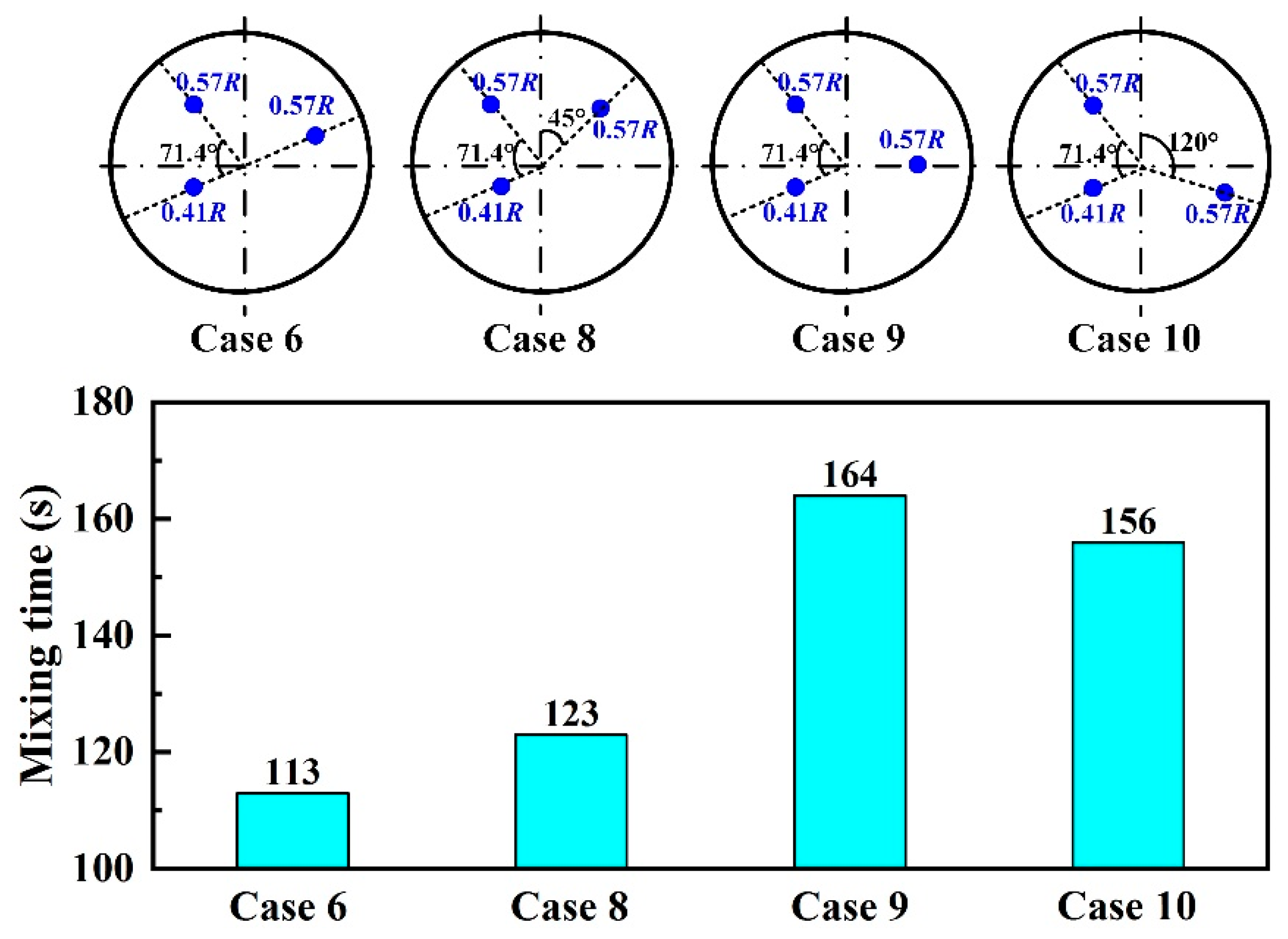
The effect of varying the angle between subsequent plugs in the triple-plug system of case 6 is shown in Figure 9. The plug angle made a big difference to the mixing time. A general feature was that the mixing time was longer when the plug angle between the two plugs closer to the wall was greater. Case 6 showed the shortest mixing time, demonstrating the optimal hydrodynamic conditions in the ladle. Figure 10 shows the effect of the plug angle on the dehydrogenation efficiency. Although there were great differences in the mixing time and the hydrodynamic conditions for cases 6, 8, and 9, almost the same dehydrogenation efficiency was displayed. This is likely because the difference in the plug angles diversified the plume–plume interaction, consequently resulting in a difference in the argon bubbles’ distribution and the bubbles–melt interface area for hydrogen mass transfer. The results showed that the highest dehydrogenation efficiency for all considered plug angle arrangements was achieved by case 6.

3.4. Argon-Purging Modes for Multi-Plugs

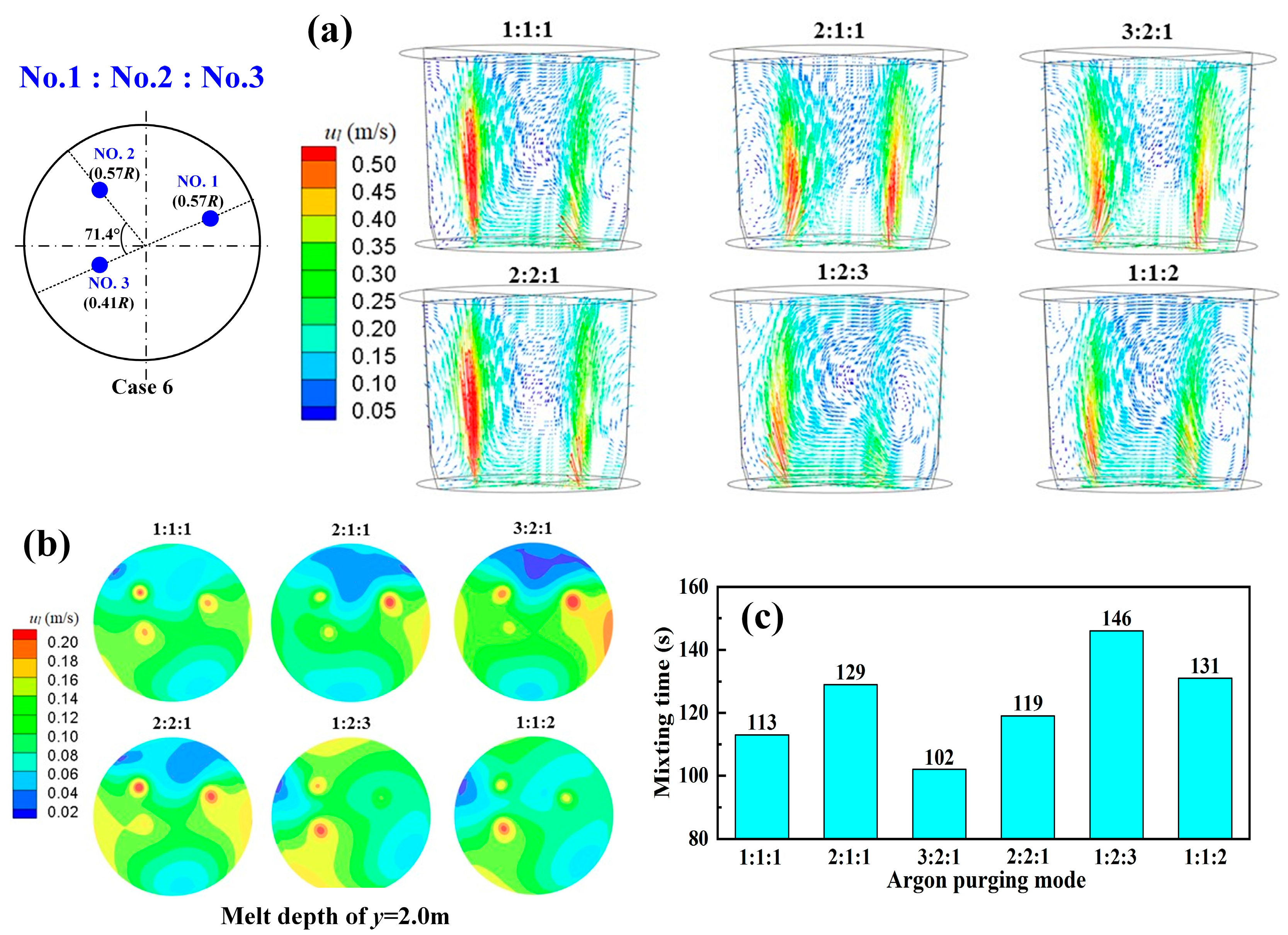
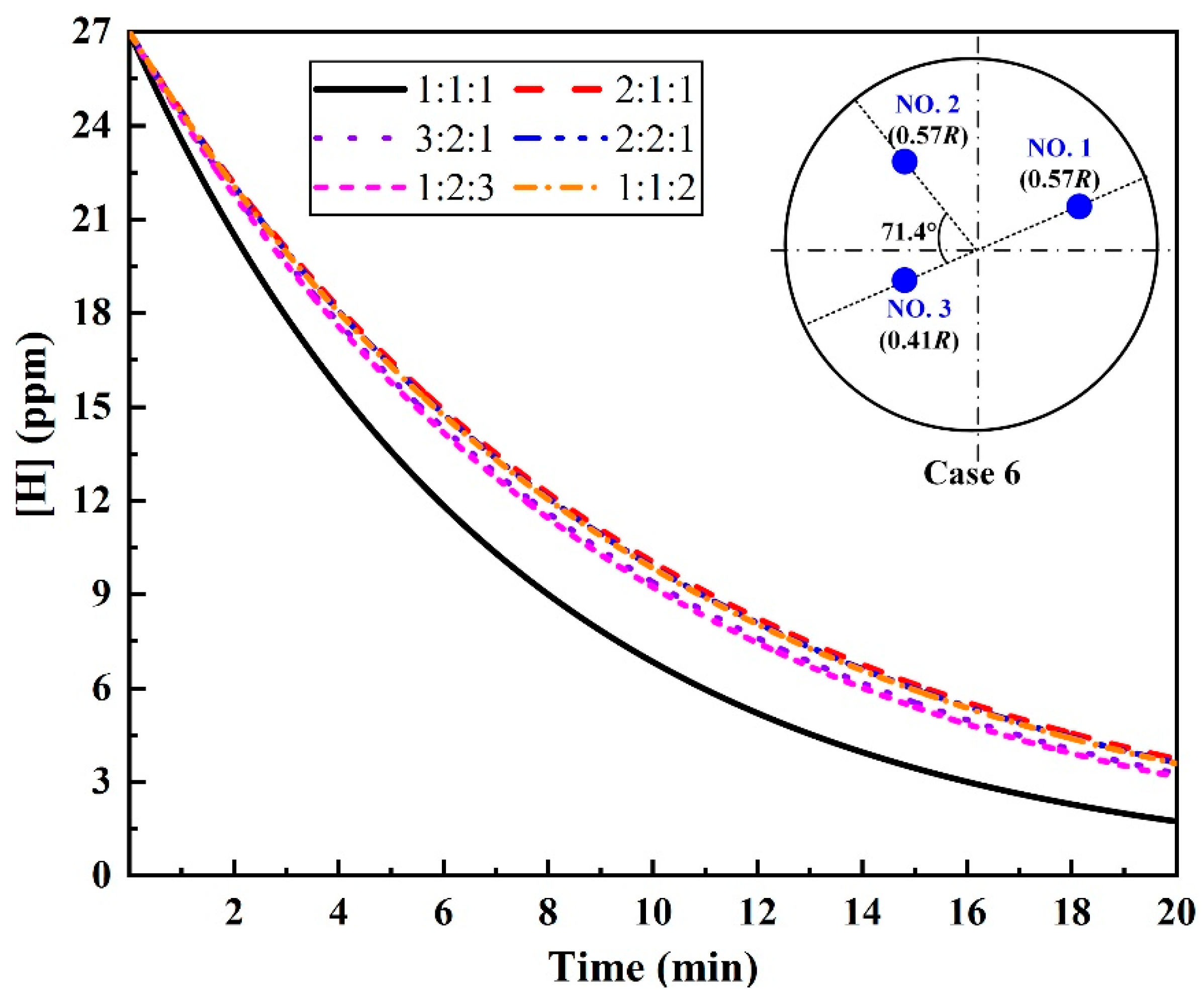
It has been acknowledged that the bottom gas-purging mode for multi-plug systems in the ladle influences the refining efficiency [30]. Therefore, the dehydrogenation efficiency under various argon-purging modes, including the uniform and non-uniform flow rates of argon-purging from the plugs, for the triple-plug layout of case 6 was further evaluated. Figure 11 shows the effect of the argon-purging mode on the melt flow and mixing in the ladle. It can be seen that for the non-uniform purging modes, such as for 2:1:1, 3:2:1, and 2:2:1 modes, the higher argon-purging flow rate of the plugs closer to the wall than that of those far from the wall caused a significantly non-uniform melt velocity field. However, the non-uniform velocity field improved as the argon flow rate of the plug far from the wall was increased. The shortest melt-mixing time (102 s) was obtained under the non-uniform argon-purging mode of 3:2:1 (Figure 11c). Nevertheless, the potential for improving the degassing performance of the non-uniform argon-purging mode is limited despite the better hydrodynamic conditions available. The hydrogen removal efficiency of the uniform argon-purging mode outperformed that of all the non-uniform ones simulated, as plotted in Figure 12.

4. Conclusions

(1)
Increasing the number of plugs improved the dehydrogenation efficiency. For H-supersaturated liquid steel, the double- and triple-plug ladles were incapable of obtaining a desired dehydrogenation efficiency under the routine degassing operation conditions, whereas it was achieved using the quadruple-plug ladle or using some triple-plug ladles under the condition of slightly prolonging the routine degassing time.
(2)
For the triple-plug ladle, varying the plug position made no significant difference to the melt hydrodynamic conditions and the dehydrogenation efficiency, both of which, however, were greatly affected by the plug angle. The melt-mixing time lengthened, and the dehydrogenation efficiency decreased when the plug angle between the two plugs closer to the wall increased.
(3)
For the triple-plug ladle, the non-uniform argon-purging mode, increasing the argon flow rate of the plugs closer to the wall and decreasing that of those far from the wall, improved the melt hydrodynamic conditions. However, the optimal dehydrogenation performance was achieved with the uniform argon-purging mode.
(4)
Of all the ladle designs considered, the plug number had the greatest impact on the dehydrogenation efficiency. For highly efficient dehydrogenation of H-supersaturated liquid steel in the VD, the quadruple-plug ladle produced the highest efficiency, followed by the triple-plug ladle with the plug positions of 0.57R, 0.57R, and 0.41R, and the plug angles of 108.6° and 71.4°, using the uniform argon-purging flow rate.

Author Contributions

Conceptualization, L.S., M.L. and Z.Z.; methodology, L.S. and Y.Y.; software, Y.Y.; validation, Y.Y.; formal analysis, M.L.; investigation, B.D. and Y.Y.; resources, B.D.; data curation, Y.Y.; writing—original draft preparation, B.D. and M.L.; writing—review and editing, M.L. and Z.Z. All authors have read and agreed to the published version of the manuscript.

Funding

This research received no external funding.

Data Availability Statement

Not applicable.

Acknowledgments

This work was supported by the National Natural Science Foundation of China (No. 51904062), the Fundamental Research Funds of the Central Universities of China (No. N2225021), and the Open Project Program of Anhui Province Key Laboratory of Metallurgical Engineering and Resources Recycling (Anhui University of Technology) (No. SKF22-01).

Conflicts of Interest

The authors declare no conflict of interest.

References

  1. Sabat, K.C.; Rajput, P.; Paramguru, R.K.; Bhoi, B.; Mishra, B.K. Reduction of oxide minerals by hydrogen plasma: An overview. Plasma Chem. Plasma Process. 2014, 34, 1–23. [Google Scholar] [CrossRef]
  2. Sabat, K.C.; Murphy, A. Hydrogen plasma processing of iron ore. Metall. Mater. Trans. B 2017, 48, 1561–1594. [Google Scholar] [CrossRef]
  3. Seftejani, M.N.; Schenk, J. Thermodynamic of liquid iron ore reduction by hydrogen thermal plasma. Metals 2018, 8, 1051. [Google Scholar] [CrossRef] [Green Version]
  4. Behera, P.R.; Bhoi, B.; Paramguru, R.K.; Mukherjee, P.S.; Mishra, B.K. Hydrogen plasma smelting reduction of Fe2O3. Metall. Mater. Trans. B 2019, 50, 262–270. [Google Scholar] [CrossRef]
  5. Filho, I.R.S.; Springer, H.; Ma, Y.; Mahajan, A.; Silva, C.C.; Kulse, M.; Raabe, D. Green steel at its crossroads: Hybrid hydrogen-based reduction of iron ores. J. Clean Prod. 2022, 340, 130805. [Google Scholar] [CrossRef]
  6. Ren, X.C.; Chu, W.Y.; Su, Y.J.; Li, J.X.; Qiao, L.J. Effects of Atomic hydrogen and flaking on mechanical properties of wheel steel. Metall. Mater. Trans. B 2007, 38, 1004–1011. [Google Scholar] [CrossRef]
  7. Fan, J.K.; Chen, H.T.; Zhao, W.; Yan, L. Study on flake formation behavior and its influence factors in Cr5 steel. Materials 2018, 11, 690. [Google Scholar] [CrossRef] [Green Version]
  8. Sano, M.; Mori, K. Bubble Formation from Single Nozzles in Liquid Metals. Trans. ISIJ 1976, 17, 344–352. [Google Scholar] [CrossRef] [Green Version]
  9. Dembovsky, V. Thermodynamics of dissolution and liberation of gases in the atomization of molten metals by plasma-induced expansion. J. Mater. Process Technol. 1997, 64, 65–74. [Google Scholar] [CrossRef]
  10. Gedeon, S.A.; Eagar, T.W. Assessing hydrogen-assisted cracking fracture modes in high-strength steel weldments. Weld. J. 1990, 69, 213–220. [Google Scholar]
  11. Steneholm, K.; Andersson, M.; Tilliander, A.; Jönsson, P.G. Removal of hydrogen, nitrogen and sulphur from tool steel during vacuum degassing. Ironmak. Steelmak. 2013, 40, 199–205. [Google Scholar] [CrossRef]
  12. Zhang, G.L.; Cheng, G.G.; Dai, W.X.; Huang, Y.; Wang, Q.M. Study on dehydrogenation behaviour of molten steel in single snorkel refining furnace (SSRF) by a mathematical model. Ironmak. Steelmak. 2021, 48, 909–918. [Google Scholar] [CrossRef]
  13. Yu, S.; Louhenkilpi, S. Numerical simulation of dehydrogenation of liquid steel in the vacuum tank degasser. Metall. Mater. Trans. B 2013, 44, 459–468. [Google Scholar] [CrossRef]
  14. Yu, S.; Miettinen, J.; Shao, L.; Louhenkilpi, S. Mathematical modeling of nitrogen removal from the vacuum tank degasser. Steel Res. Int. 2015, 86, 466–477. [Google Scholar] [CrossRef]
  15. Karouni, F.; Wynne, B.P.; Talamantes-Silva, J.; Phillips, S. Hydrogen degassing in a vacuum arc degasser using a three-phase eulerian method and discrete population balance model. Steel Res. Int. 2018, 89, 1700550. [Google Scholar] [CrossRef]
  16. Karouni, F.; Wynne, B.P.; Talamantes-Silva, J.; Phillips, S. Modeling the effect of plug positions and ladle aspect ratio on hydrogen removal in the vacuum arc degasser. Steel Res. Int. 2018, 89, 1700551. [Google Scholar] [CrossRef]
  17. Zhang, J.; Liu, J.H.; Yu, S.J.; Su, X.F.; Yan, B.J.; Yang, H. Bubble growth and floating behavior during degassing process of molten steel/(N2, H2) system. ISIJ Int. 2020, 60, 470–480. [Google Scholar] [CrossRef] [Green Version]
  18. Zhang, Y.X.; Chen, C.; Lin, W.M.; Yu, Y.C.; E, D.Y.; Wang, S.B. Numerical simulation of tracers transport process in water model of a vacuum refining unit: Single snorkel refining furnace. Steel Res. Int. 2020, 91, 2000022. [Google Scholar] [CrossRef]
  19. Ouyang, X.; Lin, W.; Luo, Y.; Zhang, Y.; Fan, J.; Chen, C.; Cheng, G. Effect of salt tracer dosages on the mixing process in the water model of a single snorkel refining furnace. Metals 2022, 12, 1948. [Google Scholar] [CrossRef]
  20. Geng, D.Q.; Zhang, X.; Liu, X.A.; Wang, P.; Liu, H.T.; Chen, H.M.; Dai, C.M.; Lei, H.; He, J.C. Simulation on flow field and mixing phenomenon in single snorkel vacuum degasser. Steel Res. Int. 2015, 86, 724–731. [Google Scholar] [CrossRef]
  21. Song, K.; Jokilaakso, A. CFD modeling of multiphase flow in an SKS furnace: The effect of tuyere arrangements. Metall. Mater. Trans. B 2021, 52, 1772–1788. [Google Scholar] [CrossRef]
  22. Xiao, J.B.; Yan, H.J.; Schubert, M.; Liu, L.; Döß, A.; Schleicher, E.; Hampel, U. Effect of nozzle geometry on centerline gas holdup in submerged gas injection. Metall. Mater. Trans. B 2021, 52, 4002–4011. [Google Scholar] [CrossRef]
  23. Li, Q.; Pistorius, P.C. Interface-resolved simulation of bubbles–metal–slag multiphase system in a gas-stirred ladle. Metall. Mater. Trans. B 2021, 52, 1532–1549. [Google Scholar] [CrossRef]
  24. Li, Q.; Pistorius, P.C. Toward multiscale model development for multiphase flow: Direct numerical simulation of dispersed phases and multiscale interfaces in a gas-stirred ladle. JOM 2021, 73, 2888–2899. [Google Scholar] [CrossRef]
  25. Haas, T.; Schubert, C.; Eickhoff, M.; Pfeifer, H. Numerical Modeling of the Ladle Flow by a LES-Based Eulerian–Lagrange Approach: A Systematic Survey. Metall. Mater. Trans. B 2021, 52, 903–921. [Google Scholar] [CrossRef]
  26. Villela-Aguilar, J.J.; Ramos-Banderas, J.; Hernández-Bocanegra, C.A.; Solorio-Díaz, G. Optimization of the mixing time using asymmetrical arrays in both gas flow and injection positions in a dual-plug ladle. ISIJ Int. 2020, 60, 1172–1178. [Google Scholar] [CrossRef] [Green Version]
  27. Li, M.M.; Yang, Y.; Yu, S.; Shao, L.; Zou, Z.S. A Numerical study on dehydrogenation of liquid steel supersaturated with hydrogen in a vacuum degasser (VD). Metall. Mater. Trans. B 2023, 1–12. [Google Scholar] [CrossRef]
  28. Sheng, Y.Y.; Irons, G.A. Measurement and modeling of turbulence in the gas/liquid two-phase zone during gas injection. Metall. Trans. B 1993, 24, 695–705. [Google Scholar] [CrossRef]
  29. Weinstein, M.; Elliott, J.F. Solubility of hydrogen in liquid iron alloys. Trans. Met. Soc. AIME 1963, 227, 378–382. [Google Scholar]
  30. Tang, H.Y.; Guo, X.C.; Wu, G.H.; Wang, Y. Effect of gas blown modes on mixing phenomena in a bottom stirring ladle with dual plugs. ISIJ Int. 2016, 56, 2161–2170. [Google Scholar]
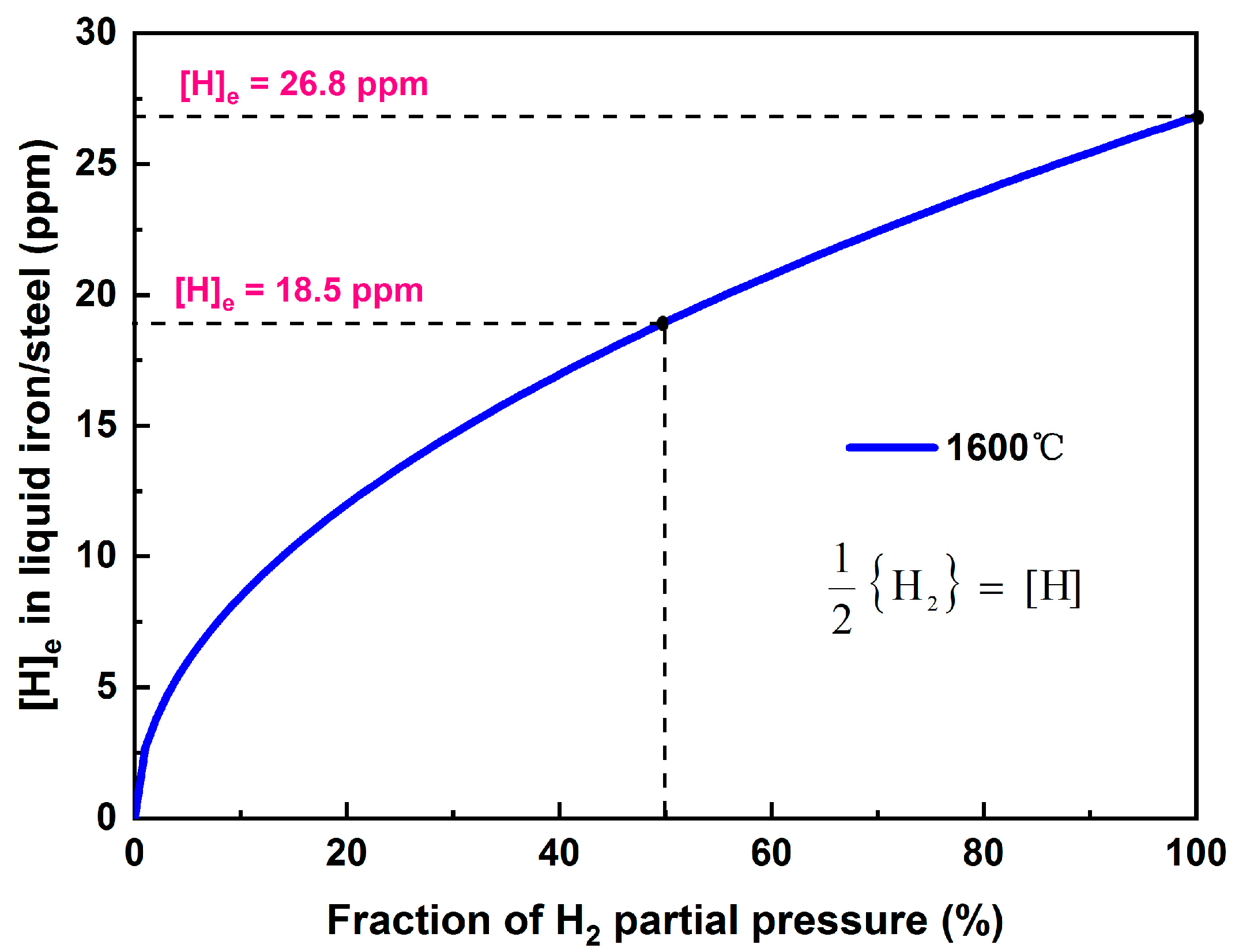
Figure 1. Equilibrium hydrogen content in liquid iron/steel as a function of the H2 partial pressure at 1600 °C.
Metals 13 01229 g001
Figure 2. (a) Schematic of the VD ladle, and (b) the typical operating condition for dehydrogenation in the VD.
Metals 13 01229 g002
Figure 3. Flow chart of the mathematical models.
Metals 13 01229 g003
Figure 4. Effect of plug number on (a) argon plumes, (b) velocity streamline, (c) velocity distribution of melt at planes of y = 0.5 m and 1.5 m, and (d) the mixing time of the melt.
Metals 13 01229 g004
Figure 5. Effect of plug number on dehydrogenation.
Metals 13 01229 g005
Figure 6. Effect of the plug number on the final hydrogen content at 18 and 20 min of degassing.
Metals 13 01229 g006
Figure 7. Effect of the plug positions on the mixing time of the melt.
Metals 13 01229 g007
Figure 8. Effect of the plug positions on dehydrogenation.
Metals 13 01229 g008
Figure 9. Effect of plug angles on the mixing time of the melt.
Metals 13 01229 g009
Figure 10. Effect of plug angles on dehydrogenation.
Metals 13 01229 g010
Figure 11. Effect of argon-purging modes on: (a) the melt velocity field on vertical planes through plug Nos. 1 and 2, (b) the melt velocity distribution on horizontal planes at a melt depth of 2.0 m, and (c) the melt-mixing time.
Metals 13 01229 g011
Figure 12. Effect of the argon-purging modes on dehydrogenation.
Metals 13 01229 g012
Table 1. Governing equations for multiphase flow and dehydrogenation models in the VD.
Continuity
equation
α q ρ q u q = 0 αq—volume fraction of phase q
ρq—density of phase q
uq—velocity of phase q
p—pressure
g—acceleration of gravity
μeff—effective viscosity, μ eff = μ l + μ t
μt—turbulent viscosity, μ t = C μ ρ l k l 2 ε l
μl—molecular viscosity
Fpq—interfacial force
Fdrag, Flift, FTD—drag, lift, and turbulent dispersion forces, respectively
CL—lift coefficient, CL = 0.1
CD—drag coefficient
db—bubble diameter
Re—Reynolds number
λRT—Rayleigh–Taylor instability wavelength
Momentum equation α q ρ q u q u q = α q p + α q μ eff , q u q + α q ρ q g + F pq F drag = 3 C D α g α l ρ l 4 d b u g u l u g u l
F lift = C L α g ρ l u g u l × × u l
F TD = 3 4 C D α g d b u g u l 0.5 α g μ t , l / ρ l 0.9 α g α g α l α l

C D = C vis = 24 Re 1 + 0.1 Re 0.75 C D < C vis C dis = 2 3 d b λ RT 1 + 17.67 f 6 / 7 18.67 f ; f = 1 α g 1.5 C dis < C dis < C cap C cap = 8 3 1 α g 2 C dis > C cap
Turbulence model ρ mix k u mix = μ t , mix σ k k + G k ρ mix ε + S k ρ mix ε u mix = μ t , mix σ ε ε + ε k C 1 ε C 2 ε ρ mix ε + S ε
S k = C k 1 α g 1 α g G k + C k 2 C f α g ρ l k
S ε = C ε 1 α g 1 α g G k ε k + C ε 2 C f α g ρ l ε
Gk—production of turbulence kinetic energy
Sk, Sε—source terms
C1ε = 1.44, C2ε = 1.92
σk = 1.0, σε = 1.3
Ck1 = 6.0, Ck2 = 0.75
Cε1 = 4.0, Cε2 = 0.6
Hydrogen transport equation t α q ρ q Y i , q + α q ρ q Y i , q u q = α q J H , q + S H , q Yi,q—mass fraction of hydrogen
JH,q—diffusive flux
SH,q—source term
Dehydrogenation rate at bubble surface d [ % H ] d t b = N ρ l A Ar W k H [ % H ] [ % H ] b eq A—argon bubble surface area
kH—mass transfer coefficient
W—weight of liquid steel
N—number of argon bubbles
[%H]—hydrogen content in steel
[%H]eq—equilibrium hydrogen content
hcri—critical bath depth for nucleation
Dehydrogenation rate at steel surface d [ % H ] d t s = ρ l A open eye W k H [ % H ] [ % H ] s eq
Dehydrogenation rate in bulk steel d [ % H ] d t in = ρ l A W k in 0 h cri [ % H ] [ % H ] in eq d h
Disclaimer/Publisher’s Note: The statements, opinions and data contained in all publications are solely those of the individual author(s) and contributor(s) and not of MDPI and/or the editor(s). MDPI and/or the editor(s) disclaim responsibility for any injury to people or property resulting from any ideas, methods, instructions or products referred to in the content.