Article

Investigation of the Supercapacitive Behavior of Electroless Ni-B Coatings

1
Institute of Physical Metallurgy, Metal Forming and Nanotechnology, University of Miskolc, 3515 Miskolc, Hungary
2
Department of Materials Physics, Eötvös Loránd University, 1117 Budapest, Hungary
3
Bay Zoltán Nonprofit Ltd. for Applied Research, 1116 Budapest, Hungary
*
Author to whom correspondence should be addressed.
Metals 2023, 13(7), 1233; https://doi.org/10.3390/met13071233
Submission received: 8 June 2023 / Revised: 28 June 2023 / Accepted: 29 June 2023 / Published: 5 July 2023

Abstract

:
Amorphous electroless Ni-B coatings were deposited on steel substrates with different surface morphologies and B contents (6.5–8.64 wt.%) that could be changed by altering the temperature and the composition of the baths. The supercapacitive behavior of the coatings was evaluated by cyclic voltammetry and galvanostatic charge–discharge measurements, and it was found that Ni-B coatings had higher capacitance than pure electroless Ni or the bulk Ni plate. A close relationship was identified between the microstructure, the B content, and the capacitive behavior of the coatings. The presence of the B alloying element had the most significant effect in determining the capacitance, while the surface area and particle size also contributed to its increase. A surface-specific capacity of 31 mF/cm2 was achieved by the coating containing the highest B content and largest AFM surface area. Furthermore, it was revealed that the particle size of the deposits was determined by the combined effect of the bath temperature and the B content under the applied experimental conditions. The obtained results indicate that Ni-B coatings are promising candidates for supercapacitive applications.

1. Introduction

Ni-based electroless coatings, namely Ni-P and Ni-B, have been extensively studied in recent years due to their useful properties for industry. Ni-P coatings have relatively high hardness, good solderability, and are resistant to corrosion, while Ni-B coatings are well-known for their excellent mechanical characteristics, such as their high resistance to wear and surface stress, which exceed even those of hard chromium coatings [1,2,3,4,5,6,7].
The electroless method itself possesses a specific combination of properties, such as the possibility of co-depositing non-metallic elements, uniform deposit thickness, precise weight control, and amorphous/nanocrystalline coating structure that make these coatings suitable for other types of applications, such as catalysis and electrochemical applications [8,9,10,11,12].
Recently, the application of Ni-P coatings as electrode materials for supercapacitor applications has been proposed [13,14]. Supercapacitors are efficient energy-storage devices that convert and store energy in an electrostatic or electrochemical way [15,16]. Based on their energy storage mechanism, two main types of SCs can be distinguished: electric double-layer capacitors (EDLCs) and pseudocapacitors. EDLCs utilize simple charge-separation mechanisms at the surface of the electrode/electrolyte, while pseudocapacitors are based on fast redox reactions confined to the interfacial area [17,18]. EDLC electrodes utilize mostly different carbonaceous materials [19,20], while mainly different transition metal oxides (e.g., RuO2, MnO2, Co3O4, NiO, and V2O5) [21,22], hydroxides (Ni(OH)2, and Co(OH)2) [23], and sulfides (e.g., CoSx and NiS) [24] exhibit pseudocapacitive properties. Ni-oxides/hydroxides are reported to have superior specific capacitance owing to the fast redox reactions of different oxidation states; however, one of their major drawbacks is their poor conductivity, which considerably limits the practical capability of such oxide/hydroxide-based electrodes, especially at fast scan rates or high current densities during charge–discharge processes [25,26,27,28,29,30]. In contrast, amorphous Ni-P and Ni-B alloys possess more metallic properties; thus, they have lower electrical resistivity and display greater electrocatalytic activity [31,32,33]. By applying acid etching, the initial capacity of Ni-P coating (20 F/g) could be increased to 1254 F/g (at 1 A/g) [14]. Furthermore, research has shown that Ni-phosphides [34] and Ni-phosphates [35] are also promising candidates as active materials for supercapacitive applications.
However, in the case of Ni-B, very few studies have been reported regarding its supercapacitive behavior. Li et al. [36] studied the pseudocapacitive performance of ultra-fine amorphous Ni-B alloy particles. The as-prepared Ni-B alloy showed a specific capacitance of 2230 F/g (at 1 A/g) and performed well as the positive electrode material of a supercapacitor cell. The properties of Ni-B coatings, such as their surface morphology, B content, hardness, and wear- and corrosion-resistance can be tuned by altering the bath constituents or the deposition temperature [37,38,39,40]. As the surface morphology defines the specific surface area of the coating and the B content determines the fine amorphous/nanocrystalline structure of the coating, it is expected that the supercapacitive properties can also be affected.
The aim of this study is to investigate the supercapacitive behavior of an amorphous electroless Ni-B alloy deposited as a coating, that has not been reported in the literature to date. One of the main advantages of direct deposition onto the current collector is the minimization of the electrical contact resistance between the active material and the substrate. In addition to the electrochemical studies, we provide new advances in the scientific field of Ni-based pseudocapacitors by exploring the relationship between the surface morphology, structure, and composition of the deposited coatings and their supercapacitive behavior.

2. Experimental

2.1. Preparation of Electroless Ni-B and Ni Coatings

Electroless Ni-B and pure Ni coatings were deposited on AISI 1345 steel plates (20 mm × 17 mm × 1 mm). The composition of the steel is listed in Table 1. Prior to deposition, a 5-step surface treatment process was applied:
  • Grinding with #600 and #800 SiC paper;
  • Polishing;
  • Five minutes of ultrasonic cleaning in acetone;
  • Ten minutes of degreasing in NaOH (10 wt.%) solution;
  • Thirty seconds of surface activation in cc. HCl (37 wt.%) solution.
Distilled water rinsing was performed after each step.
The surface morphology and B content of Ni-B coatings can be easily modified by changing the different deposition parameters [37,41,42]. On this basis, 4 different Ni-B coatings were deposited by altering the bath composition (concentrations of NiCl2 and NaBH4) and deposition temperature, as listed in Table 2. The baths contained 10–40 g/L NiCl2 (VWR Chemicals Ltd., using NiCl2·6H2O), 90 g/L EDA (VWR Chemicals Ltd.), 90 g/L NaOH (Scharlab Ltd.), 0.8–1.2 g/L NaBH4 (Sigma-Aldrich), and 1 mg/1 thiourea (Reanal Private Ltd.). The first number in the sample name refers to the concentration of Ni salt (10, 20, or 40 g/L) while the second number indicates the bath temperature (80 or 85 °C). In order to study the effect of the presence of B alloying element, a pure electroless Ni coating was also deposited on the steel samples using the bath composition and operating conditions listed in Table 3. The bath comprised 15 g/L Ni-acetate (Thermo Scientific), 5.95 g/L Na2-EDTA (Reanal Private Ltd.), 13.5 g/L lactic acid (Molar Chemicals Ltd.), 20 g/L hydrazine (Scharlab Ltd.), and 7.5 g/L NaOH.

2.2. Material Characterization

The surface morphology of the electroless coatings was studied using a Helios G4 PFIB CXe plasma focused-ion-beam scanning electron microscope (PFIB-SEM) equipped with an EDAX Octane Elect EDS System with APEXTM Analysis Software. The particle size of the coatings was determined by means of image analysis using ImageJ software, fitting a mesh to the images and measuring the size of the particles intersected by the lines.
The phase structure of the coatings was investigated using a Bruker D8 Discover X-ray diffractometer with Cu K-alpha radiation, 40 kV, and 40 mA generator settings. Measurements were recorded with 0.007° (2 Th)/19.2 s speed.
The specific surface area of the coatings was obtained by AIST-NT Smart SPM-1000 Atomic Force Microscopy (AFM). The samples were measured in semi-contact mode using a umasch HQ:NSC19/Al BS AFM tip. The obtained images were evaluated with the Gwyddion free SPM software, with plane level and polynomial (3rd) fitting background correction.
The boron content of the coatings was determined analytically using a Varian 720 ES inductively coupled optical emission spectrometer (ICP-OES).
Electrochemical investigation was performed using a three-electrode cell system. For comparison, the behavior of a pure bulk Ni plate (15 mm × 15 mm × 0.8 mm) was also studied. The Ni plate, and Ni and Ni-B coatings were used as the working electrode, Pt-coated platinum foil (7 mm × 7 mm) served as the counter electrode, and Ag/AgCl/3 M KCl (+0.210 vs. SHE) as the reference electrode. Cyclic voltammetry (CV) and galvanostatic charge–discharge (GCD) measurements were performed in 2 M KOH electrolyte using an Autolab PGSTAT302N potentiostat–galvanostat controlled by NOVA 2.1.5 software. Prior to the measurements, the samples were immersed in the electrolyte for 3 h to remove any air contamination. CV analysis was carried out at different scan rates (10, 20, 30, 50, or 100 mV/s) in the potential interval of 0.1…0.45 V, while GCD was performed in the interval of 0…0.45 V. The specific capacitance was determined both in units of mass and the macroscopic surface area of the electrode. The capacitance values were calculated from the results of CV and GCD by using the following equations [14,43]:
C C V = 0 Δ V I ( V )   d V 2 · Δ V · v · Π
C G C D = 2 · I · t V m a x t V m i n V t d t ( Δ V ) 2 · Π
where 0 Δ V I ( V ) is the integrated area of a cycle of a CV curve, v is the scan rate ( V s ), Δ V is the potential range of one CV cycle (V), tV(max) is the starting time of discharge during one cycle (s), tV(min) is the ending time of discharge in one cycle (s), and Π indicates the mass of the active material (coating) or the macroscopic surface area of the electrode. The capacitance values reported in the literature are usually given in terms of the mass of the active material; however, in the present study, using the macroscopic surface area of the coated electrodes is more appropriate. While the mass of the deposited coatings was different, the macroscopic surface was the same; therefore, they were suitable for studying the effect of surface characteristics and the influence of the B content on the capacitive behavior.

3. Primary Results

3.1. Composition and Specific Surface Area

The most important physical properties and the B contents of the deposited coatings are summarized in Table 4. The mass of the Ni-B coatings varied from 8 to 23 mg, while it was 24 mg for the Ni coating. The results indicated that the Ni content of the baths had a major role in determining the mass (see: NiB10-80 and NiB40-80), thus affecting the deposition rate of the Ni-B coatings, while temperature did not seem to have any considerable effect (NiB40-80 and NiB40-85) for a difference of 5 °C. Even when increasing the Ni content to 20 g/L, as well as the temperature and the concentration of the reducing agent (NiB20-85), the coating thickness deposited from the bath containing 40 g/L NiCl2 could not be achieved.
From the results of ICP measurement (Table 4), the B content of the coatings varied from 6.50 to 8.64 wt.%; thus, they could be classified as high-B coatings [31]. Increasing the NiCl2 content of the bath led to an increase in the B content as well, while a higher temperature (85 °C) had no effect on the composition (NiB40-80 and NiB40-85).
The surface area of the coatings was determined using AFM (Figure 1). The AFM images showed that both Ni-B and Ni coatings possessed a nodular structure, which is usually characteristic of electroless Ni-based coatings [41,44,45]. The size of these nodules was between 1 and 10 µm and increased with the Ni concentration of the baths. The effect of temperature could also be observed in the case of samples NiB40-80 and NiB40-85. At a lower temperature (80 °C), the nodules consisted of smaller nanoparticles, resulting in a cauliflower-like structure [46,47]. The surface area of the samples was calculated from the ratio of the surface measured by AFM and the projected surface (Table 4). The AFM surface differed only 4–9% from the nominal flat surface; thus, there was no considerable difference between the surface area of the samples. Sample NiB10-80, with the smallest nodule size, had the largest surface area, while the smallest value was measured for sample EN.

3.2. Surface Morphology and Microstructure

The surface morphology of the coatings was further studied at a higher resolution using the PFIB-SEM technique, and the obtained images are shown in Figure 2. Interestingly, the size of the nodules remained the same as the temperature increased (NiB40-85); nevertheless, their fragmented structure could no longer be observed. As temperature was the only variable deposition parameter between the two samples, it influenced the mechanism of the coating’s build-up. The presence of finer particles could be explained by the nucleation mechanism. According to the observations of Rao et al. [48], a large number of nuclei started to grow at the onset of deposition due to the high concentration of reactants in the vicinity of the substrate. With time, the growth of particles overcame the nucleation, resulting in a columnar growth that, after some time changed to a nodular growth (as nucleation became the dominant mechanism again) due to the presence of an ion-depleted diffusion layer in the vicinity of the growing particles. In the present case, the baths were continuously stirred, introducing a forced convection to the baths, thus preventing the formation of an ion-depleted layer. At a higher temperature (85 °C), however, the growth of particles took place at a higher rate, overtaking the speed of nucleation, resulting in smooth, uniform nodules. Meanwhile, at a lower temperature (80 °C), the nucleation mechanism could compete with particle growth, allowing finer particles to be formed (Figure 2a,b). It was reported that the cauliflower-like structure could be attributed to the presence of heavy metals in the bath [49]. Based on the present results, it can be stated that temperature could also contribute to the formation of a structure, similar to cauliflowers, as no heavy metal salts were used in this study, which is in accordance with the observations of Yunacti et al. [40] and Bonin et al. [50].
Figure 3 shows the average particle size that built up the deposited coatings. Electroless Ni (EN) and NiB10-80 contained finer, nano-sized particles distributed over smaller size ranges of 70–600 nm and 20–300 nm, respectively. When increasing the Ni-concentration of the bath, the particle size also increased (NiB10-80 and NiB40-80). The same tendency applied to the effect of the temperature increment (NiB40-80 and NiB40-85). However, when lowering the Ni concentration of the bath (from 40 to 20 g/L), the particle size decreased, even though the concentration of the reducing agent was elevated (NiB20-85). It is important to note that these nodular particles did not reflect the fine crystalline/amorphous structure of the coatings. After the heat treatment of the coatings, the surface morphology usually remains the same, while the crystallization and precipitation of NixBy phases take place [37,51].
The XRD patterns of Ni-B and Ni coatings, as well as the bulk Ni plate, are shown in Figure 4. The high-intensity characteristic Ni peaks referred to the microcrystalline structure of the Ni plate. In the case of the coatings, ferrite reflections were visible at 2Θ = 44.5°, 65°, and 82.5°, which originated from the steel substrate. At 2Θ = 44.5°, both Ni and ferrite peaks are expected to appear, while Ni has other reflections at 2Θ = 52° and 77°. However, in the case of the Ni-B samples, only a broad peak of Ni at 2Θ = 44.5° could be observed near the ferrite reflection, which referred to the X-ray amorphous structure of the coatings. These observations are in agreement with the literature, as it was reported, that high-B electroless Ni-B coatings are amorphous in the as-deposited state and consist of microcrystalline Ni and amorphous Ni-B phases, with an increasing amorphous phase ratio as a function of the B content [52,53]. For NiB10-80, the small peak of austenite at 2Θ = 43.5° could also be observed, which was not visible in the case of the other coatings. This was attributed to the lower mass, i.e., the smaller thickness of the coating (Table 4), as the thinner coating was more transparent to the X-ray. However, in the case of the pure Ni coating (EN), a relatively higher intensity diffraction peak could be seen at 2Θ = 44.5°, while the width of the amorphous peak was also reduced. Furthermore, Ni peaks at higher 2Θ values also appeared. These observations referred to an ordered atomic arrangement, i.e., to the crystalline structure of the coating compared with the Ni-B samples [54]. It can be concluded that the obtained results confirmed the observations of the effect of the B content on the formation of an amorphous phase reported in the literature [55,56].

3.3. Electrochemical Behavior

The deposited coatings and the Ni plate were analyzed with CV and GCD measurements to study their capacitive electrochemical behavior and to provide us with the necessary parameters to calculate their specific capacitance.

3.3.1. CV

The potential window of the CV measurements was optimized to obtain the expected redox peaks of Ni-based pseudocapacitors and to avoid the decomposition of the electrolyte [57,58]. Figure 5 shows the results of CV measurements. The observed anodic and cathodic peaks refer to faradaic reactions (oxidation and reduction respectively) taking place at the interfacial area between the electrode and the electrolyte, thus resulting in pseudocapacitive behavior [58]. The symmetry of the peaks refers to the reversible nature of the redox reactions. Strikingly, the shape of the curves was very similar, except for the curve of the Ni plate, which was flatter, presenting considerably lower peak currents. For all the coatings, oxidation–reduction started at around 0.3 V, while the onset of oxidation shifted to around 0.33 V for the Ni plate. The anodic and cathodic peaks of the CV curves occurred due to the reversible conversion of Ni2+⟷Ni3+. In the case of Ni-B alloys in alkaline media (KOH in this case), the conversion can be expressed by the following redox reactions [36,58,59]:
N i 2 + + 2 O H N i ( O H ) 2
N i ( O H ) 2 + O H N i O O H + H 2 O + e
N i B x + 6 x + 2 O H N i ( O H ) 2 + x B O 3 3 + 3 x H 2 O +   ( 3 x + 2 ) e
At a lower scan rate (10 mV/s), there was a well-defined, lower-intensity second anodic and cathodic peak in the case of all of the Ni-B and Ni coatings (Figure 5a). This means that it could not be associated with the B content. In the case of Ni(OH)2, Lo et al. [60] reported two cathodic CV peaks with a slow scan rate of 1 mV/s. The peaks were identified as the reduction processes of different phase structures of γ-NiOOH and β-NiOOH, which were formed as a result of the CV cycles. On this basis, it was postulated, that the observed peaks were related to the different phase structures of Ni(OH)2 (α and β) and NiOOH.
When increasing the scan rate to 100 mV/s, the same tendency could be observed regarding the peak currents and the CV curve area of the samples; however, the two distinct cathodic and anodic peaks were superimposed and could no longer be distinguished (Figure 5b). Another difference was the shift in the reduction peaks toward more negative potentials and the anodic peaks toward more positive potentials (Figure 6). This kind of behavior is usually attributed to the increase in the internal diffusion resistance within the electrode materials [61,62,63]. The diffusion rate of electrolytic ions was not sufficient to carry out the redox reactions depicted in Equations (4) and (5). The shift in the peak potentials can be seen in Figure 6, which presents the CV curves of the NiB40-80 sample.
At both scan rates, the largest area of the CV curve was presented by NiB40-80; thus, the highest capacity was expected for this sample. When comparing sample EN with the Ni plate, it was noticeable that EN had a slightly larger CV area. It is known that both the specific surface area and the structural disorder of amorphous electroless coatings can contribute to the increment in the area of the CV curves [36,64]. As EN had a similar microcrystalline structure to the Ni plate (Figure 4), the difference was attributed to the increased surface area of the coating.
As seen in Figure 7, a linear relationship existed between the current of the anodic and cathodic peaks and the square root of the scan rate, which applied to both types of coatings (Ni-B and Ni) as well as to the Ni plate. When the scan rate and the peak currents correlated linearly, the electrode reactions were related to adsorption/desorption mechanisms, typical of EDLC behavior. However, when a linear relationship applies between the square root of the scan rate and the peak currents, the reactions are limited by diffusion mechanisms, i.e., the interfacial kinetics and the efficient transport rate are reduced at higher scan rates [14,65]. In this case, the observed relationship supports the pseudocapacitive behavior, the faradaic redox reactions, that were discussed earlier.

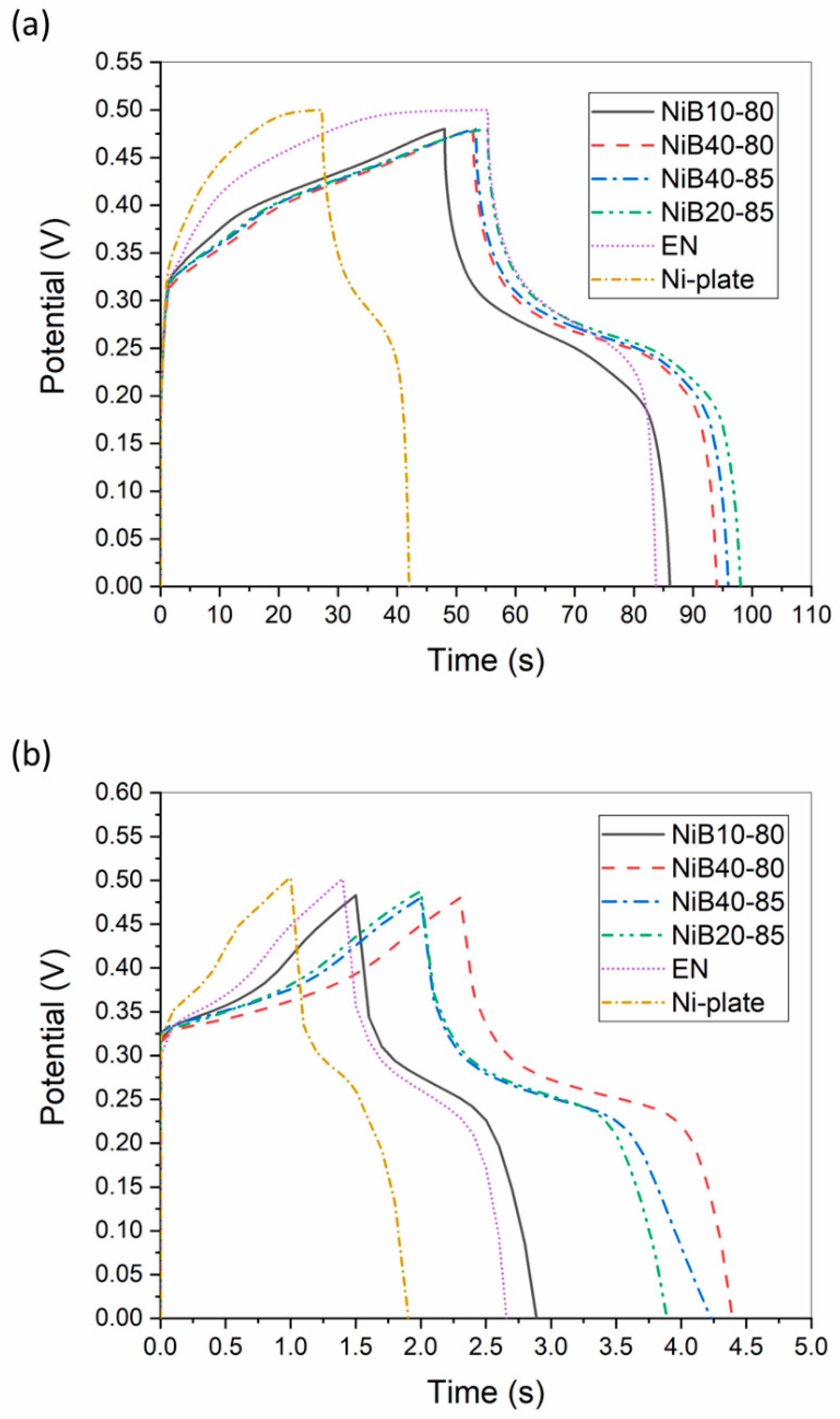
3.3.2. GCD Measurement

Galvanostatic charge–discharge tests were performed to further analyze the electrochemical behavior of the samples with different discharge current densities. The measurement produced quasi-symmetric curves, as seen in Figure 8. The non-linear shape of the slopes corresponding to the charge–discharge processes confirmed the pseudocapacitive nature of the samples [66]. The time difference required for a charge–discharge cycle between the Ni plate and the electroless coatings was more pronounced with a lower discharge current (Figure 8a). The time required for one cycle was at least two times longer for the coatings than for the Ni plate, indicating higher charge-storage capability. This was attributed to the larger surface area and supposedly to the B content of the Ni-B coatings. As shown, the charging potential range slightly decreased to 0.48 V for the electroless coatings. After charging, the potential dropped rapidly in the interval of 0.5 and 0.3 V, followed by a plateau of a slower potential drop. The interval of the rapid potential drop referred to the cathodic peak of CV curves (Figure 5), while the inflection point of this section corresponded to the cathodic peak currents [14,67].

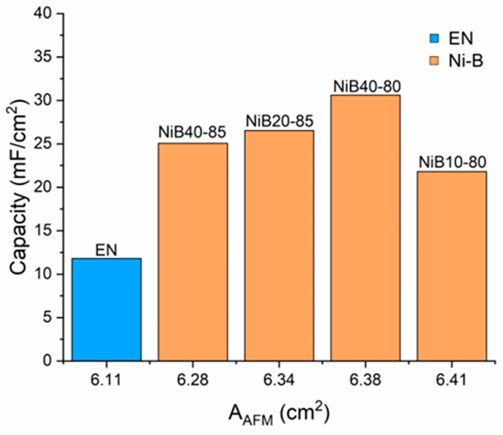
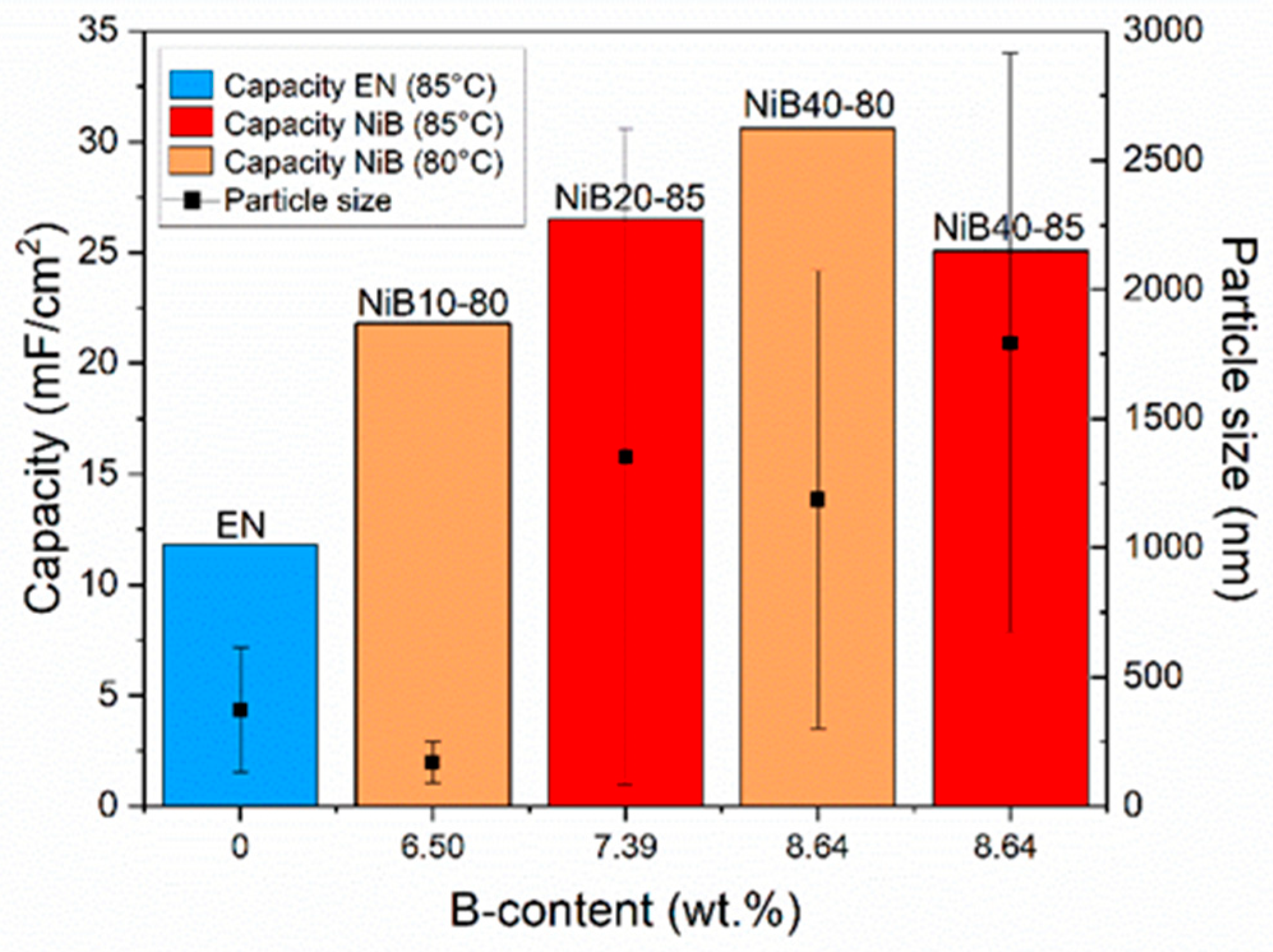
3.3.3. Specific Capacitance

Specific capacitances were calculated from the CV and GCD tests. For comparison with the values reported in the literature, gravimetric capacities were also included. The surface-specific and gravimetric capacities as a function of the scan rate are shown in Figure 9a,b respectively. As seen in Figure 9a, the highest capacitance was achieved for sample NiB40-80, reaching the highest value of 31 mF/cm2. The capacitance of the other Ni-B coatings was situated in the range of 22–27 mA/cm2, while EN and the Ni plate had approximately the same value of 12 mA/cm2. These results suggest that the B content had a distinctive role in determining the capacities of the electroless coatings. Meanwhile, at higher scan rates, a 4% AFM surface area difference of the EN sample compared with the bulk Ni plate (Table 4) was also reflected in the capacitance values.
As expected, the tendency of the capacitive behavior was completely different in the case of the gravimetric capacities (Figure 9b). The mass difference of the coatings was reflected mainly in the obtained values, as determined by Equation (1). As such, NiB10-80, with the lowest mass, showed the best capacitive behavior, while the coatings with the largest mass reached the lowest capacitance values (EN, NiB40-80, and NiB40-85). NiB10-80 reached a capacity of 16 F/g, which was very close to the values reported for Ni-P coatings [14,68]. This suggests that the B content had a similar effect on the electrochemical performance of electroless Ni-based coatings to P. When increasing the scan rate, the specific capacitances decreased to 70–80% of the maximum values for the Ni-B coatings and 60% for the electroless Ni and Ni plates (Figure 9a). As the electrode reactions were determined by diffusion (see Figure 7), with increasing scan rates, the diffusion of electrolytic ions became limited as they had less time to penetrate the fine pores of the coating. As a result, the reactions took place primarily in the top surface area of the coatings, thereby decreasing the achievable capacities [69,70].
The calculated surface-specific capacitances, as well as the gravimetric capacitances acquired by CV and GCD measurements, are listed in Table 5 and Table 6, respectively. The results clearly show that the obtained values were highly dependent on the applied scan rate and the current density; however, the trends within the specific measurements were very similar. There was only one discrepancy, which was related to the surface-specific capacities of EN and the Ni plate. As there was only a small difference between the values calculated from CV, in the case of GCD, EN had a larger capacitance than the Ni plate (1 mA/cm2). However, with increasing current density (5 mA/cm2), the ratio of these values approached the ratio acquired with CV measurements. These differences were due to the complex mechanisms embedded in the two measurement methods.
Based on the obtained result, it is important to note that the choice of scan rate/current density should be carefully considered and should depend on the specific objectives of the analysis. Higher scan rates can be useful for studying the overall electrochemical behavior and reducing the influence of surface processes, but they may also mask certain phenomena that occur at slower rates. Therefore, it is necessary to choose an appropriate scan rate/current density that balances the desired experimental conditions and the specific information needed from the cyclic voltammetry measurements.

4. Discussion

In this section, we are looking for the connection between the structural/chemical properties of the coatings investigated in Section 3.1 and Section 3.2 and their supercapacitive behavior. Figure 10 shows the specific capacity of the coatings as a function of their B content. As can be seen, the capacitance increased linearly with the B content, fitting the correlation with an appropriate coefficient of determination (R2 = 0.8986). The first datapoint of the Ni-B coatings is relatively far from that of pure Ni; however, to acquire a low B content, usually, the use of another reducing agent (DMAB) is required [31]. The enhancing effect of the B alloying element can be ascribed to the combined effect of the following factors: (a) B is a very electronegative element (χ = 2.04, with an equilibrium potential of −1.81 V vs. NHE, in alkaline medium) [59], carrying the potential to act as a high-energy-density electrode material. Although B has relatively low conductivity (1 × 10⁻⁶–7 × 10⁻⁸  S c m ), the B element is uniformly dispersed in the matrix of the Ni-B alloy phase, resulting in a conductivity close to that of metals [59]; (b) Transition metal–boride alloys possess a special electronic structure, an ionic bond between the metal and boron atoms, that is different from the usually covalent bond of transition metal–boride compounds, and from the metallic bond as well. Transition metals donate electrons to B, weakening its chemical stability while improving the chemical activity and weakening the passivation effect of the surface metal atoms [59,71]; (c) The presence of B promotes the formation of a disordered amorphous structure (see Figure 4), thereby decreasing the lattice energy, which facilitates fast ion intercalation/deintercalation on the surface during the charging–discharging processes [72].
Interestingly, it is also noticeable that two different capacitance values were measured for the coatings with the same B contents (8.64 wt.%). This suggests that it is not only the B content that determines the capacitive behavior of Ni-B coatings.
The relationship between the AFM surface area of the coatings and their capacitance is shown in Figure 11. As discussed earlier, pure electroless Ni (EN) has the lowest surface area and capacitance. In the case of Ni-B coatings, the capacitance increased in the first three samples, but then decreased with a further surface area increase. This might be contradictory at first sight, as studies on pseudocapacitive behavior report on the positive effect of the specific surface area [16,73,74]. However, it should be considered that AFM only measures the curvature of the surface particles and cannot inform us about the actual pore structure. To take the pore structure into consideration, we need another parameter. The PFIB-SEM images revealed that the pore structure of the coatings was largely determined by the boundaries of the fine particles that built up the coating (Figure 2). Thus, the particle size distribution of the coatings (Figure 3) could be used to characterize the surface area available to the electrolyte [75].
To understand the role of the factors that determine capacity, we should investigate the connection between them. The relationship between the B content, the surface area, and the particle size is presented in Figure 12. Based on the primary results, it is reasonable to examine the relationships of the parameters within the two temperatures separately. As shown, the higher B content of the coatings resulted in a decrease in the AFM surface area of the samples while increasing the particle size at both 80 °C and 85 °C. The decrease in the AFM surface area of the coating was most likely due to the increase in the size of the particles, i.e., to the coarsening effect [9], which can be expressed by the following formula (assuming that the particles have regular spherical shapes):
A s p   p = A p V p = 6 d p
where A s p   p is the specific surface area of the particles, A p is the surface area of the particles (nm2), V p is the volume of the particles (nm3), and d p is the particle diameter (nm). With increasing particle diameter, the specific surface of the particle decreased, which resulted in the decrease in the surface area of the coating as well. Similar observations were reported by Baskaran et al. [38], as the particle size of the electroless Ni-B coatings increased with increasing B content. From Figure 12, it can be seen that it was not only the B content that determined the particle size, but also the temperature, the effect of which was mentioned earlier in Section 3.2.
Figure 13 shows the capacitance and particle size as functions of the B content of the coatings. As discussed before, the B content clearly enhanced the capacity of the coatings. In the case of the samples containing the same amount of B (8.64 wt.%), a larger capacitance value was achieved with a smaller particle size i.e., higher porosity of the coatings. As mentioned earlier, the porosity of the coatings was due to the presence of boundaries between the fine particles. The width of these boundaries was in the range of 10–200 nm (Figure 2); thus, it could be accessed by the electrolytic ions, increasing the active sites on the surface, and finally resulting in an increase in the capacitance.

5. Conclusions

Amorphous high-B electroless Ni-B coatings were deposited directly onto the surface of AISI 1345 steel. The surface morphology and B content of the coatings were successfully modified by changing the concentration of the bath constituents (namely the NiCl2 ion source and NaBH4 reducing agent) and the bath temperature (80 °C and 85 °C). It was found that the combined interaction of the B content and deposition temperature had a strong influence on determining the size of the fine particles that built up the coating and, consequently, the surface area. The supercapacitive behavior of the electroless Ni-B, Ni, and the bulk Ni plate was investigated with both CV and GCD measurements. All Ni-B coatings exhibited higher capacitance values compared with electroless Ni, while the Ni coating and Ni plate showed very similar capacities. It was found that the achieved capacitances were mainly affected by the B content, surface morphology, and amorphous/microcrystalline structure of the coatings. The presence of B as an alloying element promoted the formation of an amorphous structure and resulted in a specific electronic structure between the Ni and B atoms that enhanced the charge storage capability of the coatings. In addition, the surface area and the porosity of the coatings determined by the size of the fine particles contributed to the supercapacitive behavior as well. The presence of pores increased the active sites of the electrode–electrolyte interface, thereby improving the charge-storage capability of the coatings. Hence, the highest capacitance was achieved by the NiB40-80 sample, with the highest B content and smallest particle size.

Author Contributions

Conceptualization, M.C. and P.B.; Methodology, M.C.; Format Analysis, M.C. and S.H.; Investigation, M.C. and M.W.; Writing—Original Draft Preparation, M.C.; Writing—Review and Editing, S.H.; Visualization, M.C. and P.B.; Supervision, P.B. All authors have read and agreed to the published version of the manuscript.

Funding

This research received no external funding.

Data Availability Statement

The data presented in this study are available on request from the corresponding author.

Acknowledgments

The authors would like to acknowledge the help of Adrienn Hlavacs for her assistance in the XRD investigation and Daniel Koncz-Horvath for his help in the PFIB-SEM investigations. The research work of M. Czagany was supported by the ÚNKP-22-4 New National Excellence Program of the Ministry for Culture and Innovation from the source of the National Research, Development and Innovation Fund. Project no. 2019-2.1.13-TÉT_IN-2020-00049 has been implemented with the support provided by the Ministry of Innovation and Technology of Hungary from the National Research, Development and Innovation Fund, financed under the 2019-2.1.13-TÉT_IN funding scheme.

Conflicts of Interest

The authors declare no conflict of interest.

References

  1. Zhang, X.; Wang, H.; Liu, G. Friction and Wear of Electroless Ni-P-CS Composite Coating. Metals 2023, 13, 315. [Google Scholar] [CrossRef]
  2. Czagány, M.; Baumli, P. Effect of Surfactants on the Behavior of the Ni-P Bath and on the Formation of Electroless Ni-P-TiC Composite Coatings. Surf. Coat. Technol. 2019, 361, 42–49. [Google Scholar] [CrossRef]
  3. Gul, H.; Algul, H.; Akyol, A.; Uysal, M.; Alp, A. Evaluation of Wear and Corrosion Behavior of Electroless Ni-B-P/CNT Composite Coatings on Aluminum Surfaces. Diam. Relat. Mater. 2023, 137, 110075. [Google Scholar] [CrossRef]
  4. Ma, B.; Wang, R. Tuning Interface to Improve Corrosion Resistance of Electroless Ni-P Coating on AZ31B Alloy. Metals 2018, 8, 328. [Google Scholar] [CrossRef] [Green Version]
  5. Takács, D.; Sziráki, L.; Török, T.I.; Sólyom, J.; Gácsi, Z.; Gál-Solymos, K. Effects of Pre-Treatments on the Corrosion Properties of Electroless Ni–P Layers Deposited on AlMg2 Alloy. Surf. Coat. Technol. 2007, 201, 4526–4535. [Google Scholar] [CrossRef]
  6. Gültekin, D.; Duru, E.; Akbulut, H. Improved Wear Behaviors of Lead-Free Electroless Ni B and Ni-B/CeO2 Composite Coatings. Surf. Coat. Technol. 2021, 422, 127525. [Google Scholar] [CrossRef]
  7. Gyökér, Z.; Gergely, G.; Koncz Horváth, D.; Bodnár, E.; Gácsi, Z. Role of Reinforcement Surface Treatment on the SnAg3Cu0.5 Microelectronic Joints. Appl. Surf. Sci. 2019, 475, 982–985. [Google Scholar] [CrossRef]
  8. Peeters, P.; Hoorn, G.V.D.; Daenen, T.; Kurowski, A.; Staikov, G. Properties of Electroless and Electroplated Ni–P and Its Application in Microgalvanics. Electrochim. Acta 2001, 47, 161–169. [Google Scholar] [CrossRef]
  9. Czagány, M.; Baumli, P.; Kaptay, G. The Influence of the Phosphorous Content and Heat Treatment on the Nano-Micro-Structure, Thickness and Micro-Hardness of Electroless Ni-P Coatings on Steel. Appl. Surf. Sci. 2017, 423, 160–169. [Google Scholar] [CrossRef]
  10. Zhang, P.; Lv, Z.; Liu, X.; Xie, G.; Zhang, B. Electroless Nickel Plating on Alumina Ceramic Activated by Metallic Nickel as Electrocatalyst for Oxygen Evolution Reaction. Catal. Commun. 2021, 149, 106238. [Google Scholar] [CrossRef]
  11. He, J.; Song, L.; Yan, J.; Kang, N.; Zhang, Y.; Wang, W. Hydrogen Evolution Reaction Property in Alkaline Solution of Molybdenum Disulfide Modified by Surface Anchor of Nickel–Phosphorus Coating. Metals 2017, 7, 211. [Google Scholar] [CrossRef] [Green Version]
  12. Fundo, A.M.; Abrantes, L.M. The Electrocatalytic Behaviour of Electroless Ni–P Alloys. J. Electroanal. Chem. 2007, 600, 63–79. [Google Scholar] [CrossRef]
  13. Wang, D.; Kong, L.-B.; Liu, M.-C.; Zhang, W.-B.; Luo, Y.-C.; Kang, L. Amorphous Ni–P Materials for High Performance Pseudocapacitors. J. Power Sources 2015, 274, 1107–1113. [Google Scholar] [CrossRef]
  14. Lin, J.-D.; Chou, C.-T. The Influence of Acid Etching on the Electrochemical Supercapacitive Properties of Ni P Coatings. Surf. Coat. Technol. 2017, 325, 360–369. [Google Scholar] [CrossRef]
  15. Li, D.; Liu, H.; Liu, Z.; Huang, Q.; Lu, B.; Wang, Y.; Wang, C.; Guo, L. Copper Oxide Nitrogen-Rich Porous Carbon Network Boosts High-Performance Supercapacitors. Metals 2023, 13, 981. [Google Scholar] [CrossRef]
  16. Poonam; Sharma, K.; Arora, A.; Tripathi, S.K. Review of Supercapacitors: Materials and Devices. J. Energy Storage 2019, 21, 801–825. [Google Scholar] [CrossRef]
  17. Adedoja, O.S.; Sadiku, E.R.; Hamam, Y. An Overview of the Emerging Technologies and Composite Materials for Supercapacitors in Energy Storage Applications. Polymers 2023, 15, 2272. [Google Scholar] [CrossRef]
  18. Bhojane, P. Recent Advances and Fundamentals of Pseudocapacitors: Materials, Mechanism, and Its Understanding. J. Energy Storage 2022, 45, 103654. [Google Scholar] [CrossRef]
  19. Nuilek, K.; Wongwiriyapan, W.; Sattayarut, V.; Simon, A.; Koncz-Horváth, D.; Ferenczi, T.; Kristály, F.; Baumli, P. Comparison of Acid Exfoliators in Carbon Nanosheets Synthesis from Stinging Nettle (Urtica Dioica) for Electrochemical Applications. Sci. Rep. 2020, 10, 17270. [Google Scholar] [CrossRef]
  20. Dubey, R.; Guruviah, V. Review of Carbon-Based Electrode Materials for Supercapacitor Energy Storage. Ionics 2019, 25, 1419–1445. [Google Scholar] [CrossRef]
  21. Augustyn, V.; Simon, P.; Dunn, B. Pseudocapacitive Oxide Materials for High-Rate Electrochemical Energy Storage. Energy Environ. Sci. 2014, 7, 1597. [Google Scholar] [CrossRef] [Green Version]
  22. Lakshmi, K.C.S.; Vedhanarayanan, B. High-Performance Supercapacitors: A Comprehensive Review on Paradigm Shift of Conventional Energy Storage Devices. Batteries 2023, 9, 202. [Google Scholar] [CrossRef]
  23. Cheng, J.P.; Zhang, J.; Liu, F. Recent Development of Metal Hydroxides as Electrode Material of Electrochemical Capacitors. RSC Adv. 2014, 4, 38893–38917. [Google Scholar] [CrossRef]
  24. Wang, J.; Dong, S.; Ding, B.; Wang, Y.; Hao, X.; Dou, H.; Xia, Y.; Zhang, X. Pseudocapacitive Materials for Electrochemical Capacitors: From Rational Synthesis to Capacitance Optimization. Natl. Sci. Rev. 2017, 4, 71–90. [Google Scholar] [CrossRef] [Green Version]
  25. Li, B.; Zheng, M.; Xue, H.; Pang, H. High Performance Electrochemical Capacitor Materials Focusing on Nickel Based Materials. Inorg. Chem. Front. 2016, 3, 175–202. [Google Scholar] [CrossRef]
  26. Yus, J.; Gonzalez, Z.; Sanchez-Herencia, A.J.; Sangiorgi, A.; Sangiorgi, N.; Gardini, D.; Sanson, A.; Galassi, C.; Caballero, A.; Morales, J.; et al. Semiconductor Water-Based Inks: Miniaturized NiO Pseudocapacitor Electrodes by Inkjet Printing. J. Eur. Ceram. Soc. 2019, 39, 2908–2914. [Google Scholar] [CrossRef]
  27. Wang, B.; Chen, J.S.; Wang, Z.; Madhavi, S.; Lou, X.W. (David) Green Synthesis of NiO Nanobelts with Exceptional Pseudo-Capacitive Properties. Adv. Energy Mater. 2012, 2, 1188–1192. [Google Scholar] [CrossRef]
  28. Sk, M.M.; Yue, C.Y.; Ghosh, K.; Jena, R.K. Review on Advances in Porous Nanostructured Nickel Oxides and Their Composite Electrodes for High-Performance Supercapacitors. J. Power Sources 2016, 308, 121–140. [Google Scholar] [CrossRef]
  29. Yuan, Y.F.; Xia, X.H.; Wu, J.B.; Yang, J.L.; Chen, Y.B.; Guo, S.Y. Nickel Foam-Supported Porous Ni(OH)2/NiOOH Composite Film as Advanced Pseudocapacitor Material. Electrochim. Acta 2011, 56, 2627–2632. [Google Scholar] [CrossRef]
  30. Hall, D.S.; Lockwood, D.J.; Bock, C.; MacDougall, B.R. Nickel Hydroxides and Related Materials: A Review of Their Structures, Synthesis and Properties. Proc. R. Soc. A 2015, 471, 20140792. [Google Scholar] [CrossRef] [PubMed]
  31. Sudagar, J.; Lian, J.; Sha, W. Electroless Nickel, Alloy, Composite and Nano Coatings—A Critical Review. J. Alloys Compd. 2013, 571, 183–204. [Google Scholar] [CrossRef] [Green Version]
  32. Hamid, Z.A.; Hassan, H.B.; Attyia, A.M. Influence of Deposition Temperature and Heat Treatment on the Performance of Electroless Ni–B Films. Surf. Coat. Technol. 2010, 205, 2348–2354. [Google Scholar] [CrossRef]
  33. Fang, J.; Chen, X.; Liu, B.; Yan, S.; Qiao, M.; Li, H.; He, H.; Fan, K. Liquid-Phase Chemoselective Hydrogenation of 2-Ethylanthraquinone over Chromium-Modified Nanosized Amorphous Ni–B Catalysts. J. Catal. 2005, 229, 97–104. [Google Scholar] [CrossRef]
  34. Wang, D.; Kong, L.-B.; Liu, M.-C.; Luo, Y.-C.; Kang, L. An Approach to Preparing Ni-P with Different Phases for Use as Supercapacitor Electrode Materials. Chem. Eur. J. 2015, 21, 17897–17903. [Google Scholar] [CrossRef] [PubMed]
  35. Pramanik, M.; Salunkhe, R.R.; Imura, M.; Yamauchi, Y. Phosphonate-Derived Nanoporous Metal Phosphates and Their Superior Energy Storage Application. ACS Appl. Mater. Interfaces 2016, 8, 9790–9797. [Google Scholar] [CrossRef]
  36. Li, W.; Wang, S.; Wu, M.; Wang, X.; Long, Y.; Lou, X. Direct Aqueous Solution Synthesis of an Ultra-Fine Amorphous Nickel–Boron Alloy with Superior Pseudocapacitive Performance for Advanced Asymmetric Supercapacitors. New J. Chem. 2017, 41, 7302–7311. [Google Scholar] [CrossRef]
  37. Vitry, V.; Bonin, L. Increase of Boron Content in Electroless Nickel-Boron Coating by Modification of Plating Conditions. Surf. Coat. Technol. 2017, 311, 164–171. [Google Scholar] [CrossRef]
  38. Agrawal, R.; Mukhopadhyay, A. Development of Ni-B Electroless Coating from Stabilizer Free Bath and Characterization of High Temperature Tribological Behaviour, Scratch and Corrosion Resistance. Surf. Topogr. Metrol. Prop. 2022, 10, 045028. [Google Scholar] [CrossRef]
  39. Agrawal, R.; Mukhopadhyay, A. Inclusion of W in Electroless Ni–B Coating Developed from a Stabilizer Free Bath and Investigation of Its Tribological Behaviour. J. Indian Chem. Soc. 2023, 100, 100966. [Google Scholar] [CrossRef]
  40. Yunacti, M.; Mégret, A.; Staia, M.H.; Montagne, A.; Vitry, V. Characterization of Electroless Nickel–Boron Deposit from Optimized Stabilizer-Free Bath. Coatings 2021, 11, 576. [Google Scholar] [CrossRef]
  41. Bulbul, F. The Effects of Deposition Parameters on Surface Morphology and Crystallographic Orientation of Electroless Ni-B Coatings. Met. Mater. Int. 2011, 17, 67–75. [Google Scholar] [CrossRef]
  42. Baskaran, I.; Sakthi Kumar, R.; Sankara Narayanan, T.S.N.; Stephen, A. Formation of Electroless Ni–B Coatings Using Low Temperature Bath and Evaluation of Their Characteristic Properties. Surf. Coat. Technol. 2006, 200, 6888–6894. [Google Scholar] [CrossRef]
  43. Laheäär, A.; Przygocki, P.; Abbas, Q.; Béguin, F. Appropriate Methods for Evaluating the Efficiency and Capacitive Behavior of Different Types of Supercapacitors. Electrochem. Commun. 2015, 60, 21–25. [Google Scholar] [CrossRef]
  44. Czagany, M.; Baumli, P. Effect of PH on the Characteristics of Electroless Ni-P Coatings. J. Min. Met. B Met. 2017, 53, 327–332. [Google Scholar] [CrossRef] [Green Version]
  45. Barati, Q.; Hadavi, S.M.M. Electroless Ni-B and Composite Coatings: A Critical Review on Formation Mechanism, Properties, Applications and Future Trends. Surf. Interfaces 2020, 21, 100702. [Google Scholar] [CrossRef]
  46. Cao, J.; Zhao, W.; Wang, X.; Zhao, Y.; Ma, P.; Jiang, W.; Song, G. The Microstructure and Tribological Behavior of Ultrasonic Electroless Ni-P Plating on TC4 Titanium Alloy with Heat-Treatment. Ferroelectrics 2022, 589, 1–11. [Google Scholar] [CrossRef]
  47. Duru, E.; Doğan, F.; Uysal, M.; Akbulut, H.; Aslan, S. Optimization of Ni-B Coating Bath and Effect of DMAB Concentration on Hardness and Wear. Surf. Interfaces 2021, 22, 100880. [Google Scholar] [CrossRef]
  48. Rao, Q.; Bi, G.; Lu, Q.; Wang, H.; Fan, X. Microstructure Evolution of Electroless Ni-B Film during Its Depositing Process. Appl. Surf. Sci. 2005, 240, 28–33. [Google Scholar] [CrossRef]
  49. Baskaran, I.; Narayanan, T.S.N.S.; Stephen, A. Effect of Accelerators and Stabilizers on the Formation and Characteristics of Electroless Ni–P Deposits. Mater. Chem. Phys. 2006, 99, 117–126. [Google Scholar] [CrossRef]
  50. Bonin, L.; Castro, C.C.; Vitry, V.; Hantson, A.-L.; Delaunois, F. Optimization of Electroless NiB Deposition without Stabilizer, Based on Surface Roughness and Plating Rate. J. Alloys Compd. 2018, 767, 276–284. [Google Scholar] [CrossRef]
  51. Pal, S.; Verma, N.; Jayaram, V.; Biswas, S.K.; Riddle, Y. Characterization of Phase Transformation Behaviour and Microstructural Development of Electroless Ni–B Coating. Mater. Sci. Eng. A 2011, 528, 8269–8276. [Google Scholar] [CrossRef]
  52. Vitry, V.; Kanta, A.-F.; Dille, J.; Delaunois, F. Structural State of Electroless Nickel–Boron Deposits (5 wt.% B): Characterization by XRD and TEM. Surf. Coat. Technol. 2012, 206, 3444–3449. [Google Scholar] [CrossRef]
  53. Kumar, P.S.; Nair, P.K. X-Ray Diffraction Studies on the Relative Proportion and Decomposition of Amorphous Phase in Electroless Ni-B Deposits. Nanostruct. Mater. 1994, 4, 183–198. [Google Scholar] [CrossRef]
  54. Haag, S.; Burgard, M.; Ernst, B. Pure Nickel Coating on a Mesoporous Alumina Membrane: Preparation by Electroless Plating and Characterization. Surf. Coat. Technol. 2006, 201, 2166–2173. [Google Scholar] [CrossRef]
  55. Çelik, İ.; Karakan, M.; Bülbül, F. Investigation of Structural and Tribological Properties of Electroless Ni–B Coated Pure Titanium. Proc. Inst. Mech. Eng. Part J J. Eng. Tribol. 2016, 230, 57–63. [Google Scholar] [CrossRef]
  56. Ekmekci, D.; Bülbül, F. Preparation and Characterization of Electroless Ni–B/Nano-SiO2, Al2O3, TiO2 and CuO Composite Coatings. Bull. Mater. Sci. 2015, 38, 761–768. [Google Scholar] [CrossRef] [Green Version]
  57. Bhat, T.S.; Patil, P.S.; Rakhi, R.B. Recent Trends in Electrolytes for Supercapacitors. J. Energy Storage 2022, 50, 104222. [Google Scholar] [CrossRef]
  58. Feng, L.; Zhu, Y.; Ding, H.; Ni, C. Recent Progress in Nickel Based Materials for High Performance Pseudocapacitor Electrodes. J. Power Sources 2014, 267, 430–444. [Google Scholar] [CrossRef]
  59. Wang, Y.D.; Ai, X.P.; Cao, Y.L.; Yang, H.X. Exceptional Electrochemical Activities of Amorphous Fe–B and Co–B Alloy Powders Used as High Capacity Anode Materials. Electrochem. Commun. 2004, 6, 780–784. [Google Scholar] [CrossRef]
  60. Lo, Y.L.; Hwang, B.J. In Situ Raman Studies on Cathodically Deposited Nickel Hydroxide Films and Electroless Ni-P Electrodes in 1 M KOH Solution. Langmuir 1998, 14, 944–950. [Google Scholar] [CrossRef]
  61. Ji, J.; Zhang, L.L.; Ji, H.; Li, Y.; Zhao, X.; Bai, X.; Fan, X.; Zhang, F.; Ruoff, R.S. Nanoporous Ni(OH)2 Thin Film on 3D Ultrathin-Graphite Foam for Asymmetric Supercapacitor. ACS Nano 2013, 7, 6237–6243. [Google Scholar] [CrossRef] [PubMed]
  62. Liang, K.; Tang, X.; Hu, W. High-Performance Three-Dimensional Nanoporous NiO Film as a Supercapacitor Electrode. J. Mater. Chem. 2012, 22, 11062. [Google Scholar] [CrossRef]
  63. Aoki, K.J.; Chen, J.; Liu, Y.; Jia, B. Peak Potential Shift of Fast Cyclic Voltammograms Owing to Capacitance of Redox Reactions. J. Electroanal. Chem. 2020, 856, 113609. [Google Scholar] [CrossRef]
  64. Lu, Y.; Liu, J.; Liu, X.; Huang, S.; Wang, T.; Wang, X.; Gu, C.; Tu, J.; Mao, S.X. Facile Synthesis of Ni-Coated Ni2P for Supercapacitor Applications. CrystEngComm 2013, 15, 7071. [Google Scholar] [CrossRef]
  65. Dong, X.; Cao, Y.; Wang, J.; Chan-Park, M.B.; Wang, L.; Huang, W.; Chen, P. Hybrid Structure of Zinc Oxide Nanorods and Three Dimensional Graphene Foam for Supercapacitor and Electrochemical Sensor Applications. RSC Adv. 2012, 2, 4364. [Google Scholar] [CrossRef]
  66. Tang, Z.; Tang, C.; Gong, H. A High Energy Density Asymmetric Supercapacitor from Nano-Architectured Ni(OH)2/Carbon Nanotube Electrodes. Adv. Funct. Mater. 2012, 22, 1272–1278. [Google Scholar] [CrossRef]
  67. Liang, K.; Tang, X.; Wei, B.; Hu, W. Fabrication and Characterization of a Nanoporous NiO Film with High Specific Energy and Power via an Electrochemical Dealloying Approach. Mater. Res. Bull. 2013, 48, 3829–3833. [Google Scholar] [CrossRef]
  68. Lin, J.-D.; Chou, C.-T. The Influence of Phosphorus Content on the Microstructure and Specific Capacitance of Etched Electroless Ni-P Coatings. Surf. Coat. Technol. 2019, 368, 126–137. [Google Scholar] [CrossRef]
  69. Vijayakumar, S.; Nagamuthu, S.; Muralidharan, G. Supercapacitor Studies on NiO Nanoflakes Synthesized Through a Microwave Route. ACS Appl. Mater. Interfaces 2013, 5, 2188–2196. [Google Scholar] [CrossRef]
  70. Pang, H.; Zhang, B.; Du, J.; Chen, J.; Zhang, J.; Li, S. Porous Nickel Oxide Nanospindles with Huge Specific Capacitance and Long-Life Cycle. RSC Adv. 2012, 2, 2257. [Google Scholar] [CrossRef]
  71. Vajeeston, P.; Ravindran, P.; Ravi, C.; Asokamani1, R. Electronic Structure, Bonding, and Ground-State Properties of AlB_{2}-Type Transition-Metal Diborides. Phys. Rev. B 2001, 63, 045115. [Google Scholar] [CrossRef] [Green Version]
  72. Miller, J.R.; Simon, P. Electrochemical Capacitors for Energy Management. Science 2008, 321, 651–652. [Google Scholar] [CrossRef] [PubMed] [Green Version]
  73. Jeong, M.-G.; Zhuo, K.; Cherevko, S.; Chung, C.-H. Formation of Nanoporous Nickel Oxides for Supercapacitors Prepared by Electrodeposition with Hydrogen Evolution Reaction and Electrochemical Dealloying. Korean J. Chem. Eng. 2012, 29, 1802–1805. [Google Scholar] [CrossRef]
  74. Qiu, H.-J.; Xu, H.-T.; Liu, L.; Wang, Y. Correlation of the Structure and Applications of Dealloyed Nanoporous Metals in Catalysis and Energy Conversion/Storage. Nanoscale 2015, 7, 386–400. [Google Scholar] [CrossRef]
  75. Baskaran, I.; Sankara Narayanan, T.S.N.; Stephen, A. Corrosion Resistance of Electroless Ni–Low B Coatings. Trans. IMF 2009, 87, 221–224. [Google Scholar] [CrossRef]
Figure 1. AFM images of the deposited coatings: (a) NiB10-80, (b) NiB40-80, (c) NiB40-85, (d) NiB20-85, and (e) EN.
Metals 13 01233 g001
Figure 2. PFIB-SEM images of the surface of electroless Ni-B and Ni coatings: (a) NiB10-80, (b) NiB40-80, (c) NiB40-85, (d) NiB20-85, (e) EN.
Metals 13 01233 g002
Figure 3. Average particle size of the deposited coatings.
Metals 13 01233 g003
Figure 4. XRD patterns of the deposited coatings and the Ni plate.
Metals 13 01233 g004
Figure 5. CV curves of the deposited coatings at scan rates of (a) 10 mV/s and (b) 100 mV/s.
Metals 13 01233 g005
Figure 6. CV curves of NiB40-80 sample at different scan rates (v = 10, 20, 30, 50, and 100 mV/s).
Metals 13 01233 g006
Figure 7. Plots of the anodic and cathodic peak currents of NiB40-80, EN, and Ni plate as functions of the square root of the scan rate.
Metals 13 01233 g007
Figure 8. GCD curves of the different coatings measured with (a) 1 mA/cm2 and (b) 5 mA/cm2.
Metals 13 01233 g008
Figure 9. (a) Surface-specific capacitance and (b) gravimetric capacitance of the deposited coatings and the Ni plate as a function of the scan rate.
Metals 13 01233 g009
Figure 10. Specific capacity of the coatings as a function of the B content.
Metals 13 01233 g010
Figure 11. Specific capacitance of the coatings as a function of their AFM surface area.
Metals 13 01233 g011
Figure 12. Particle size and AFM surface area of the coatings.
Metals 13 01233 g012
Figure 13. Capacitance and particle size of the coatings as a function of the B content.
Metals 13 01233 g013
Table 1. Chemical composition of AISI 1345 steel determined by XRF.
ElementFeMnCrCuBiPbVNi
Composition (wt.%)97.851.780.080.070.070.060.040.04
Table 2. Bath compositions and operating conditions of the deposited electroless Ni-B coatings.
Bath CompositionConcentration
NiB10-80NiB40-80NiB40-85NiB20-85
NiCl2 (g/L)10404020
EDA (g/L)90909090
NaOH (g/L)90909090
NaBH4(g/L)0.80.80.81.2
Thiourea (mg/L)1111
Conditions
pH>13
T (°C)80808585
Deposition time60 min60 min60 min60 min
Table 3. Bath composition and operating conditions of electroless Ni coating.
Bath CompositionConcentration
Ni-acetate (g/L)15
Na2-EDTA (g/L)5.95
Lactic acid (g/L)13.5
Hydrazine(g/L)20
NaOH (g/L)7.5
Conditions
pH9.4
T (°C)80
Deposition time (min)60
Table 4. Mass, B content, and AFM surface area of the deposited coatings.
NiB10-80NiB40-80NiB40-85NiB20-85EN
Mass (mg)8 ± 123 ± 123 ± 117 ± 124 ± 1
B content (wt.%)6.508.648.647.39-
B content (at.%)27.4233.9533.9530.25-
Asample (cm2)5.885.885.885.885.88
AAFM/Aproj (%)109.11108.55106.90107.90104.05
AAFM (cm2)6.416.386.286.346.12
Table 5. Surface-specific capacitances of the electroless coatings and the Ni plate.
Cs (mF/cm2)
Ni plateENNB10-80NB40-80NB40-85NB-20-85
CV
(10 mV/s)
11.6511.8121.8030.6125.0726.53
CV
(100 mV/s)
7.378.5015.2824.6121.5421.12
GCD
(1 mA/cm2)
34.91566.53083.90793.27697.618100.761
GCD
(5 mA/cm2)
1.8162.6052.9684.6224.4444.077
Table 6. Gravimetric capacitances of the electroless coatings and the Ni plate.
Cs (F/g)
Ni plateENNB10-80NB40-80NB40-85NB-20-85
CV
(10 mV/s)
-3.0116.027.826.419.75
CV
(100 mV/s)
-2.1711.236.295.507.76
GCD
(0.5 A/g)
-3.08716.9926.3425.8598.349
GCD
(1 A/g)
-0.5082.5931.1462.4301.437
Disclaimer/Publisher’s Note: The statements, opinions and data contained in all publications are solely those of the individual author(s) and contributor(s) and not of MDPI and/or the editor(s). MDPI and/or the editor(s) disclaim responsibility for any injury to people or property resulting from any ideas, methods, instructions or products referred to in the content.

