Article

Effect of Microstructure on Impact Resistance and Machinability of TiAl Alloys for Jet Engine Turbine Blade Applications

by
Toshimitsu Tetsui
National Institute for Material Science, Tsukuba 305-0047, Ibaraki, Japan
Metals 2023, 13(7), 1235; https://doi.org/10.3390/met13071235
Submission received: 9 June 2023 / Revised: 3 July 2023 / Accepted: 4 July 2023 / Published: 5 July 2023
(This article belongs to the Special Issue Advances in TiAl Alloys: Structures, Properties and Applications)

Abstract

:
The impact resistance and machinability of TiAl alloys, which are used for jet engine turbine blades, are critical for ensuring reliability and reducing manufacturing costs. This study investigated the effects of the microstructure on these properties using Ti–Al–Cr ternary alloys via Charpy impact tests at room temperature and 700 °C and performing cutting tests using a face mill with cemented carbide tools. As a result, it was confirmed that six types of typical microstructures of TiAl alloys, namely, fine FL, coarse FL, L + γ, γ, γ + β, and L + γ + β, could be formed by varying the Al and Cr concentrations and heat-treatment conditions. Impact resistance and machinability are each the exact opposite trends to the other, with coarse FL having the best impact resistance but poor machinability. Meanwhile, γ has the best machinability but the weakest impact resistance. L + γ has no major drawbacks, including creep strength. As the microstructure of TiAl4822, currently used in LEAP (leading edge aviation propulsion) engine blades, is almost a γ single-phase microstructure, we assumed that manufacturers chose this microstructure to improve machinability and thus reduce the cost. However, because the γ microstructure has the lowest impact resistance, caution should be exercised when applying it to other engines with different operating environment. On the other hand, the microstructure containing the β phase is inferior in all aspects, including creep strength. Thus, it is questionable to use TiAl-forged materials with a residual β phase in small-sized products that can be manufactured by casting.

1. Introduction

In the past, TiAl alloys were mainly used in components for the turbochargers of passenger cars [1,2] and engine valves for racing engines [3]. Currently, most are being produced for the last-stage turbine blades of jet engines such as CFM International’s LEAP [4]. The maximum operating temperature for this product is as low as 700 °C.
The effects of various additive elements and microstructural control have been investigated to improve the tensile properties [5], creep strength [6,7], fatigue strength [7,8], and oxidation resistance [9,10] of TiAl alloys. However, jet engine blades for low-temperature applications do not require high oxidation resistance or creep strength. In fact, the microstructure of TiAl4822 [11,12] (Ti-48Al-2Nb-2Cr (at.%), hereinafter, the at.% notation is omitted) currently being used in the LEAP engine is not a lamellar microstructure with high creep strength, but an almost γ single-phase microstructure with low creep strength.
Currently, most TiAl materials for jet engine blades are manufactured by casting. The material properties required for the cast material, as summarized in the product specifications, are tensile strength, tensile ductility, creep strength, and fatigue strength. However, the requirements are not severe, and even materials with an almost γ single-phase microstructure can satisfy the targets.
Impact resistance and machinability are critical parameters of TiAl alloy materials for use in jet engine blades, although they have not received much attention so far. The significance of impact resistance has only emerged since 2017 as more than 40 incidents of failure of the TNM alloy (Ti-43.5Al-4.0Nb-1.0Mo-0.1B) [13,14] blades on the Airbus A320neo have been reported [15]. The blades, which were manufactured for Pratt & Whitney’s PW1100 G, were damaged by impact from debris passing through the engine during flight. US regulatory agencies mandated that Pratt & Whitney to replace the TNM alloy with a material (not TiAl alloy) that could resist impact. Hence, impact resistance determines whether the TiAl alloy blades can be used continuously.
Machinability is essential for cost reduction. When the TiAl4822 blade was first commercialized, it was manufactured using investment casting [11], a process in which molten metal is poured into ceramic shell molds. However, the castability of TiAl alloys is extremely poor, meaning that near-net casting was impossible, as with Ni-based superalloys, and the blades were cast into a fat shape with an extremely large margin. Consequently, the merits of investment castings have been overlooked. Therefore, the current TiAl blade manufacturing process uses an ingot with a simple shape (rectangular) cast into a permanent mold [16], which is significantly cheaper than using investment castings. Thus, the entire blade is machined from this ingot. The machinability of TiAl alloy material is a prominent characteristic directly related to the manufacturing cost since this process requires an extremely large volume of machining work.
The impact resistance and machinability of TiAl alloys are thought to be influenced by the microstructure as well as additives. In our previous studies [17,18], we examined the effect of additives on the impact resistance and discovered that only appropriate amounts of Cr, V, and Mn improved the impact resistance of TiAl alloys, while all other elements (Nb, Mo, W, Fe, Ni, Si, C, N, B) weakened it. Therefore, in this study, we examined the influence of microstructure.
The microstructure, including β phase, should also be evaluated in this investigation. Therefore, in this study, we decided to add a β-stabilizing element. In TiAl alloys, a small amount of β-stabilizing element does not form β phase, but a certain amount of β-stabilizing element forms β phase. Specifically, Cr (β-stabilizing element) was selected as the third element because it improves the impact resistance of TiAl alloys. We expected to form various microstructures (including β phase) by adjusting Cr content along with Al concentration and heat-treatment conditions. Thus, in this study, the effects of microstructure on the impact resistance and machinability of TiAl alloys were assessed using Ti–Al–Cr ternary alloys. Creep strength was also evaluated as a supplement to comprehensively examine the merits and demerits of each microstructure from a practical standpoint.

2. Materials and Methods

2.1. Materials

The compositions of the Ti–Al–Cr ternary alloys investigated were six levels of Al concentration (44.0, 45.0, 46.0, 47.0, 48.0, and 49.0) and 10 levels of Cr concentration (0.0, 0.5, 1.0, 1.5, 2.0, 2.5, 3.0, 3.5, 4.0, and 4.5). A total of 60 alloys were examined by multiplying these levels. Sponge Ti, Al shot, and granular Cr were used as raw materials. These raw materials were blended into various compositions of ternary Ti–Al–Cr alloys with a charge of approximately 800 g and subsequently melted in an yttria crucible using an induction melting furnace in an atmosphere replaced by Ar after evacuation. Ceramic crucible melting is not a method normally used to melt TiAl alloys. However, after examining various crucible materials [19], we concluded that the increase in the oxygen content is small and that the mechanical properties did not weaken with yttria crucibles. As such, we decided to use this method for the experimental efficiency of sample production.
The molten metals were held for approximately 3 min while applying the melting power. They were then poured into a metal mold that was divided into two parts (Figure 1), thus producing cast material. The sampling position for test pieces in the cast material is a lower plate section with a width of 60 mm, length of 90 mm, and thickness of 16 mm.
To examine the relationship between alloy composition, heat-treatment conditions, and the microstructure formed, heat-treatment tests were initially performed on small sections cut from the castings. Four heat-treatment conditions were examined, namely 1100 °C/10 h/FC (heated at 1100 °C for 10 h, followed by furnace cooling), 1200 °C/5 h/FC, 1300 °C/2 h/FC, and 1400 °C/1 h/FC.
The microstructure of each sample was observed via the compositional image in backscattered electron mode at the polished cross section of the sample after heat treatment. To distinguish the microstructures obtained, the notation established by previous studies [20] (e.g., fully lamellar (abbreviated as FL)) was used in its existing form. For others, the phases and structures present in the backscattered electron image were listed in descending order of area ratio. In addition, the lamellar structure was expressed simply as (L). For example, a microstructure in which lamellar structure, γ phase, and β phase were present in this order of area ratio was expressed as “L + γ + β”.
This study aims to investigate the effect of microstructure on the impact resistance and machinability of TiAl alloys, as mentioned above. On the other hand, the influence of the amount of additive elements cannot be ignored. As a result of microstructural observation, it was found that similar typical microstructures were obtained using different Cr addition amounts. Therefore, multiple samples were evaluated for each representative microstructure. The selection criterion was based on a stepwise change in Cr concentration without changing the Al concentration.

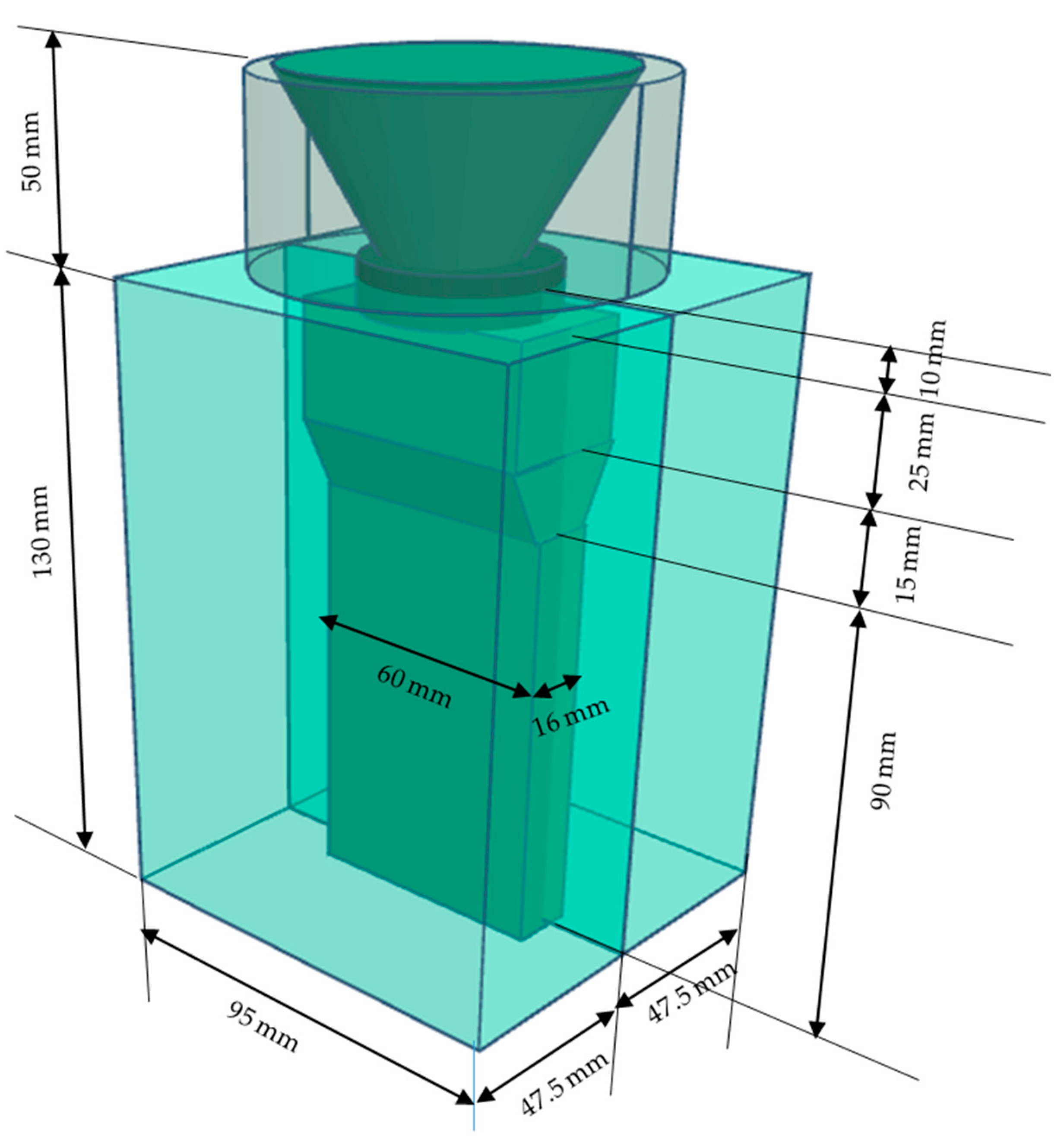
2.2. Evaluation Method of Impact Resistance

The FOD (foreign object damage) test [21] has been occasionally conducted to evaluate the impact resistance of TiAl alloys. However, for the scope of this study, FOD testing is not feasible due to its high cost and the requirement for long test duration, including preparation period, per trial. Instead, this study adopted the Charpy impact test, which is a simpler and more practical method to evaluate the impact resistance of metallic materials.
The test procedure was performed as follows. The front and rear surfaces of the sample selected by the heat-treatment test were machined to a uniform thickness of 10 mm. Subsequently, multiple prismatic test pieces of about 10 mm × 10 mm × 55 mm were produced by further processing. For TiAl alloys, when the test specimens are notched like conventional metallic materials, the absorbed energies of all the samples tend to be uniformly small, making it challenging to discern differences among the samples. Therefore, this study did not notch the specimens. A compact hammer with a capacity of 30 J was used for the Charpy impact test because a regular hammer with a capacity of 300 J or the like cannot precisely measure the small value of absorbed energy.
The impact resistance of each sample was evaluated by comparing the absorbed energies obtained in the above-mentioned Charpy impact tests. The test was conducted at room temperature and 700 °C, which is the maximum temperature for jet engine blades. Since each sample was heat-treated at 1100 °C or higher, it was considered that there was almost no microstructural change (characteristic change) when held at 700 °C for 1 h without stress.
The steps in the 700 °C Charpy impact tests are as follows. An electric furnace was installed adjacent to the testing machine. The specimens were heated to 700 °C in the furnace for approximately 1 h. Subsequently, they were removed from the furnace and swiftly placed into the testing machine to perform the Charpy impact test. After the specimens were removed, the time required to complete the test was 5–10 s. Since the absorbed energy varied to some extent, the average absorbed energy of five test pieces per sample was used to compare the impact resistance.

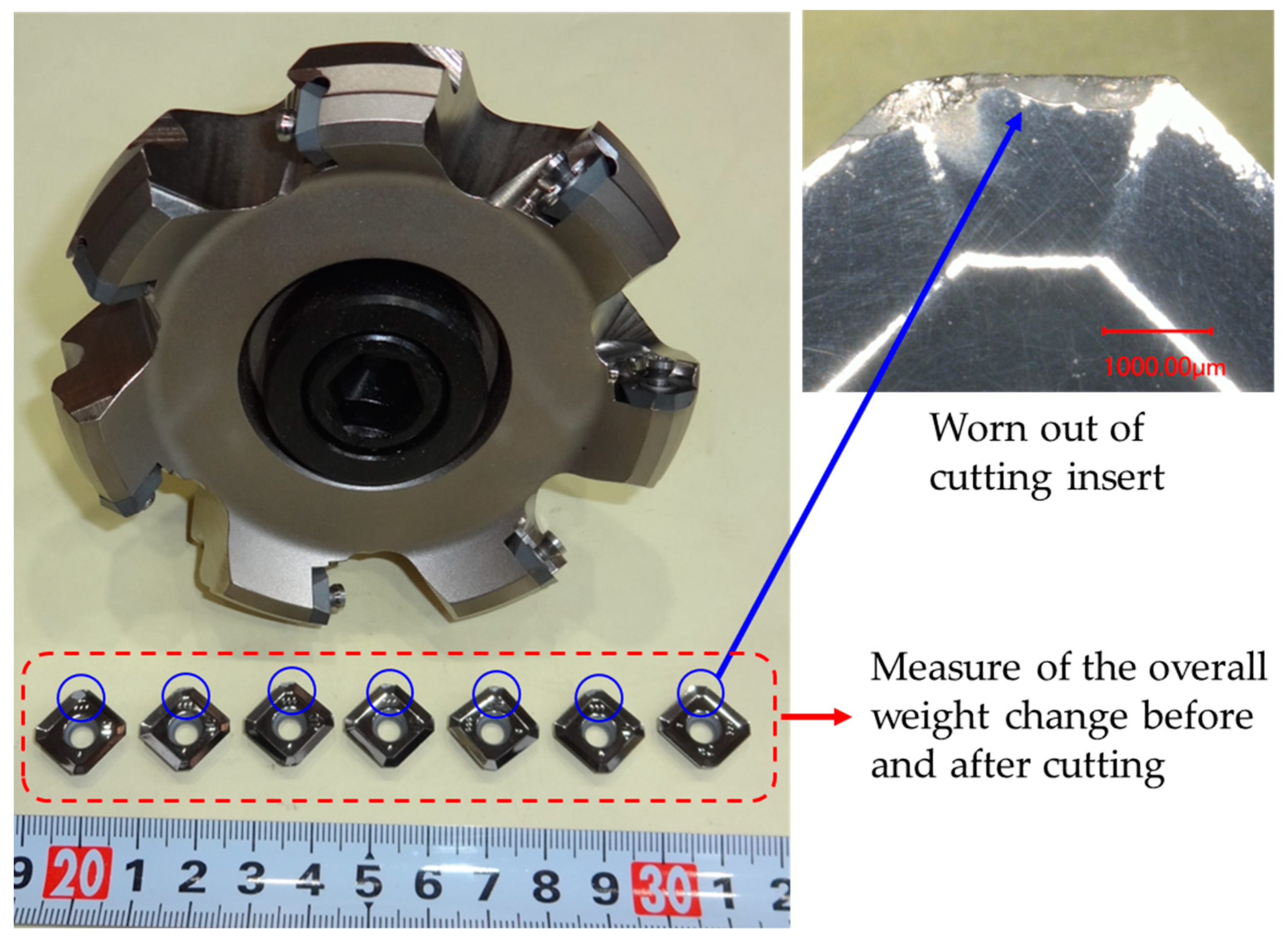
2.3. Evaluation Method of Machinability

The oxide scale and oxidation alteration layer formed on the sample surfaces by heat treatment were completely removed. Subsequently, the samples were subjected to cutting tests. The samples were machined by dry-cutting using a face milling cutter with K10 cemented carbide inserts. The cutter, inserts and the typical wear area of an insert are illustrated in Figure 2. The diameter between the centers of the insert tips when mounted on a seven-blade cutter was 100 mm. Although several studies have utilized coated tools for the machining of TiAl alloys [22,23,24,25], differences in the compositions of the alloy may affect the reactivity of the coated layer and workpiece. Lubrication conditions (dry, wet, etc.) also have a significant effect on machinability; however, as the purpose of this study was to compare the relative machinability of each microstructure, coating-free K10 cemented carbide inserts were used in dry milling under constant conditions. Approximately 100 g of sample was removed by cutting at a rotational speed of 130 rpm (peripheral speed of the insert tip was 0.680 m/s), feed rate of 4.97 mm/s, and depth of cut of 0.2 mm per cycle.
The occurrence of surface defects on the workpiece and the amount of tool wear were evaluated. Although the maximum flank wear is often measured to evaluate tool wear, it is a two-dimensional metric and does not quantitatively reproduce three-dimensional wear on real tools. Therefore, in this study, the wear weight of the tool was determined by measuring the change in the total weight of the seven inserts before and after cutting, and samples with less tool weight loss were considered to have better machinability. A high-resolution analytical balance with a minimum unit of 0.01 mg was used for this measurement.

2.4. Other Evaluation Tests

As a supplement to the process of comprehensively determining the merit and demerit of each microstructure practically, the samples of each representative microstructure were subjected to a 200 MPa creep test at 725 °C.

3. Results and Discussion
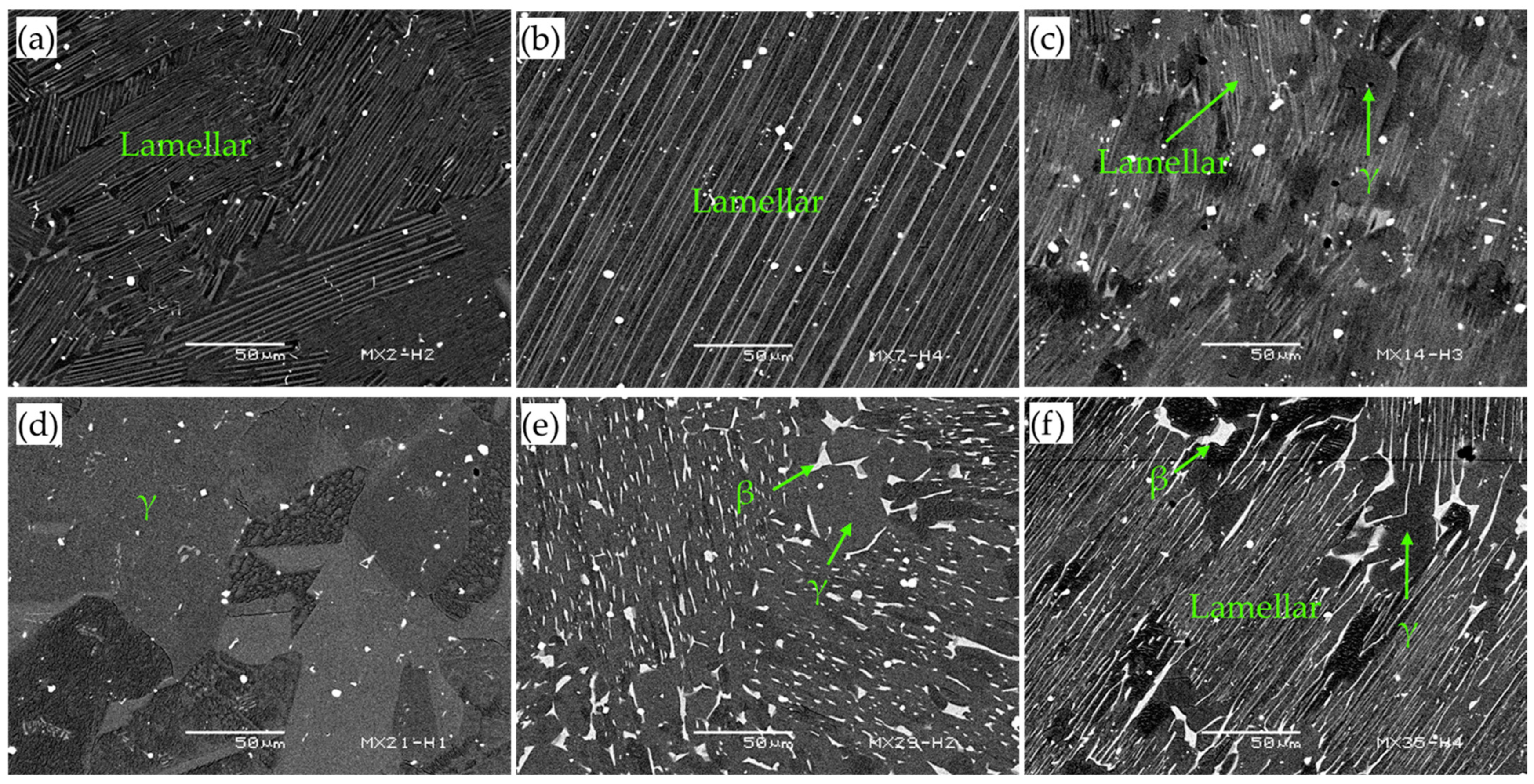
3.1. Microstructure

Figure 3 distinguishes between the microstructures formed after the four heat-treatment conditions of each Ti–Al–Cr ternary alloy using color coding. Six types of microstructures were observed: fine FL (fully lamellar structure with small colony size), coarse FL (fully lamellar structure with large colony size), L + γ (a microstructure formed by lamellar structure with a large area ratio and γ phase with a small area ratio), γ (a microstructure formed only by γ phase), γ + β (a microstructure formed by γ phase with large area ratio and β phase with small area ratio), and L + γ + β (a microstructure in which the lamellar structure, γ phase, and β phase exist in this order of area ratio).
Generally, in TiAl alloys, when the Cr content is small, the β phase does not exist. However, as the Cr content increases, the β phase increases. Also, when the Al concentration increases, the amount of γ phase increases and the amount of α2 phase that constitute the lamellar structure (α2/γ) decreases. Therefore, the microstructures containing β phase (γ + β, L + γ + β) were obtained with 3.0 at.% Cr or more. All other microstructures were formed with 2.5 at.% Cr or less; among them, the γ single-phase structure was formed in 48 Al or more. In addition, microstructures including lamellar structures were formed at a lower Al concentration. These included most of the typical microstructures in TiAl alloys [20,26]. The backscattered electron images of representative samples of each microstructure are depicted in Figure 4. The distinction of each microstructure, the alloy composition, and the heat-treatment conditions under which it was formed, are as described in Figure 4. The evaluation of the impact resistance and machinability of each microstructure was performed using samples, the composition and heat-treatment conditions of which are circled in bold in Figure 3. In this evaluation, samples with a stepwise variation in Cr concentration at the same Al concentration were used.

3.2. Impact Resistance

Figure 5 depicts the relationship between the Charpy absorbed energy and the Cr concentration for each microstructure, namely (a) fine FL, (b) coarse FL, (c) L + γ, (d) γ, (e) γ + β, and (f) L + γ + β at room temperature and 700 °C. In all microstructures, the absorbed energy at 700 °C was more than twice that at room temperature, which can be attributed to the improvement of ductility at 700 °C while maintaining a certain strength level. The results for each microstructure are as follows (a summary is provided in Table 1 below):
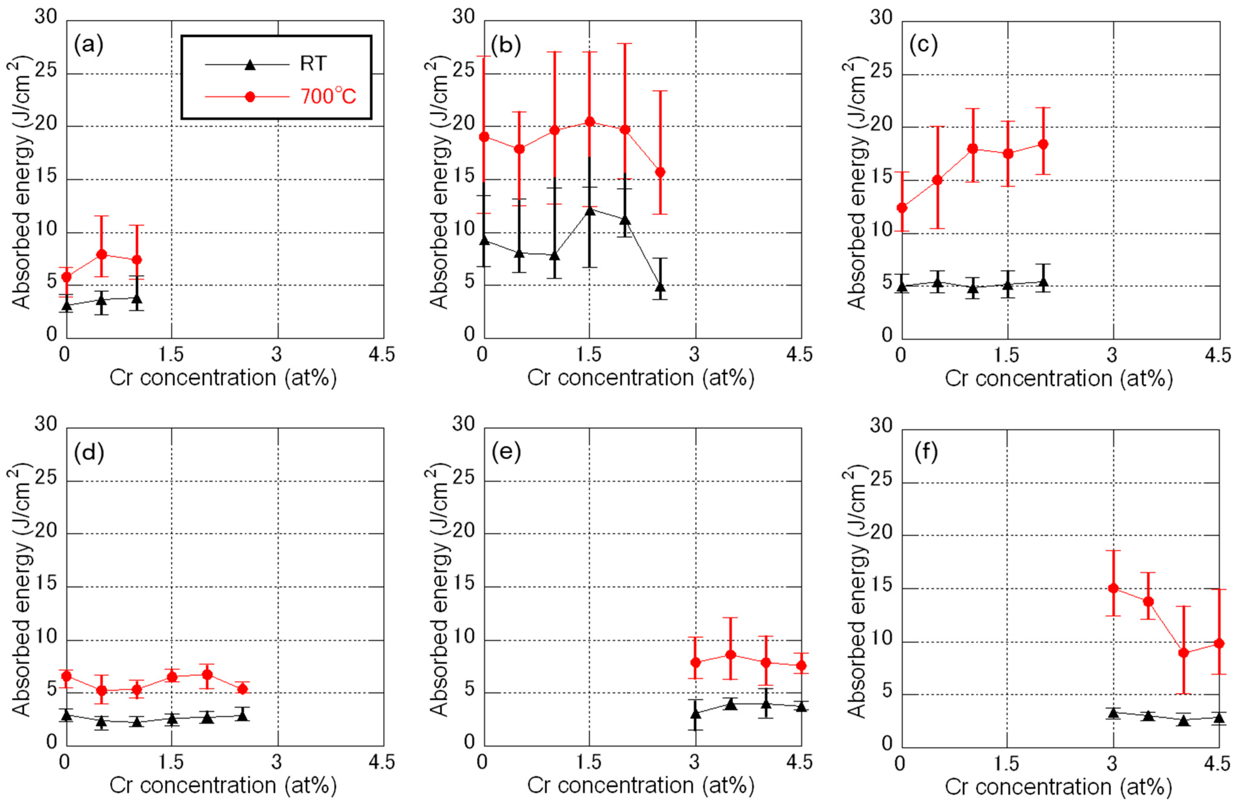
  • Fine FL: This microstructure has relatively low absorbed energies at both room temperature and 700 °C. A subtle increase in absorbed energy was observed as the Cr concentration increased.
  • Coarse FL: This microstructure exhibits the highest absorbed energy at both room temperature and 700 °C. Especially at room temperature, the absorbed energies increased at 1.5 and 2.0 at.% Cr, which was deemed an appropriate range for the amount of Cr addition.
  • L + γ: This microstructure has the second-highest absorbed energy at room temperature, although this is considerably inferior to that of coarse FL. However, at 700 °C, it improved significantly and approached that of coarse FL. The reason for this may be the significant improvement in ductility.
  • γ: This microstructure shows the lowest absorbed energy at both room temperature and 700 °C. In other words, it is the microstructure with the lowest impact resistance.
  • γ + β: This microstructure has only marginally better impact resistance than γ.
  • L + γ + β: This microstructure has poor impact resistance at room temperature. At 700 °C, however, the absorbed energy significantly increased when 3 at.% Cr was added. This can be attributed to the effect of the β phase greatly improving the ductility. However, at 4 at.% Cr or more, the amount of low-strength β phase at high-temperature became excessively large, resulting in a decrease in the impact resistance.
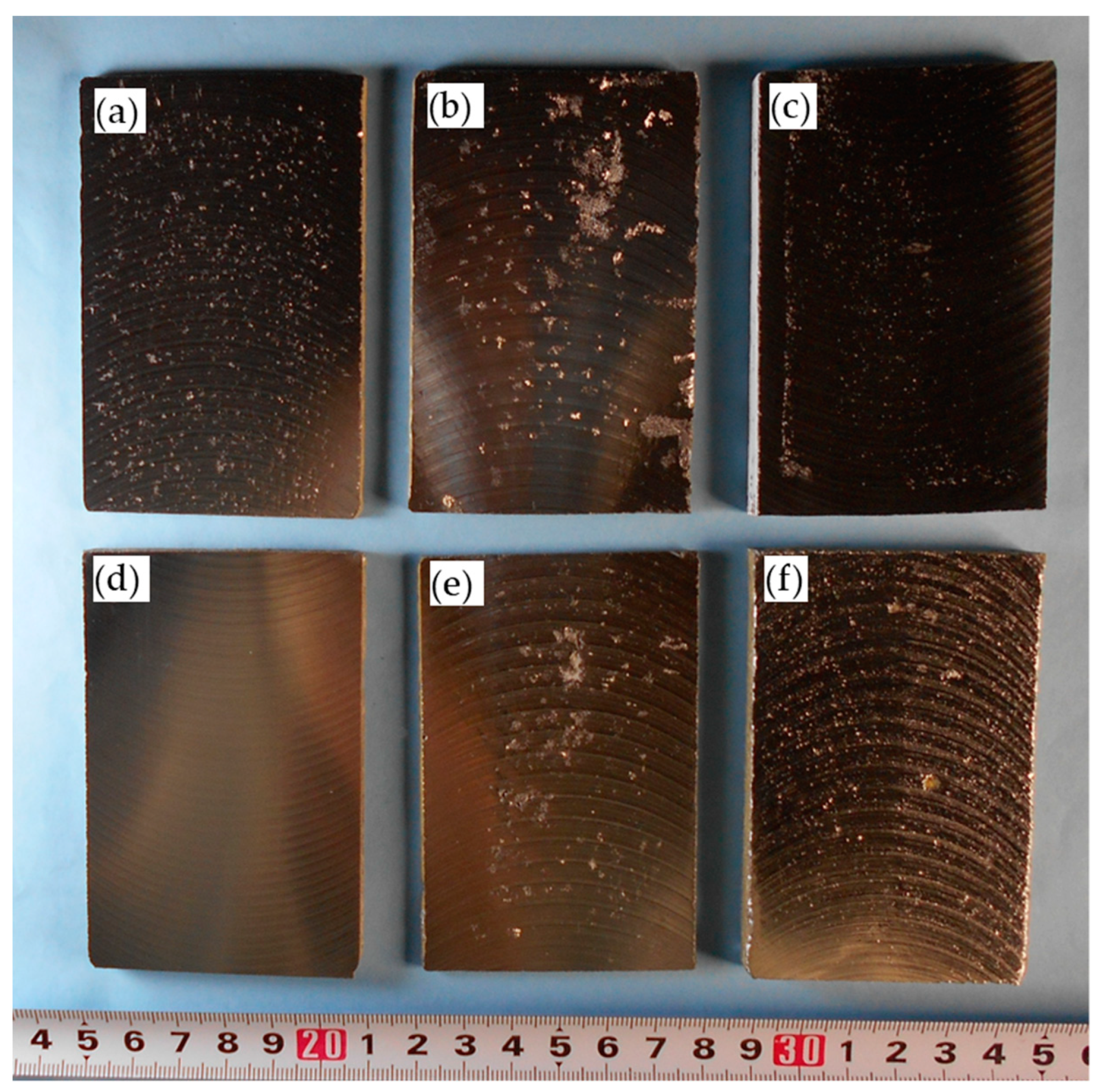
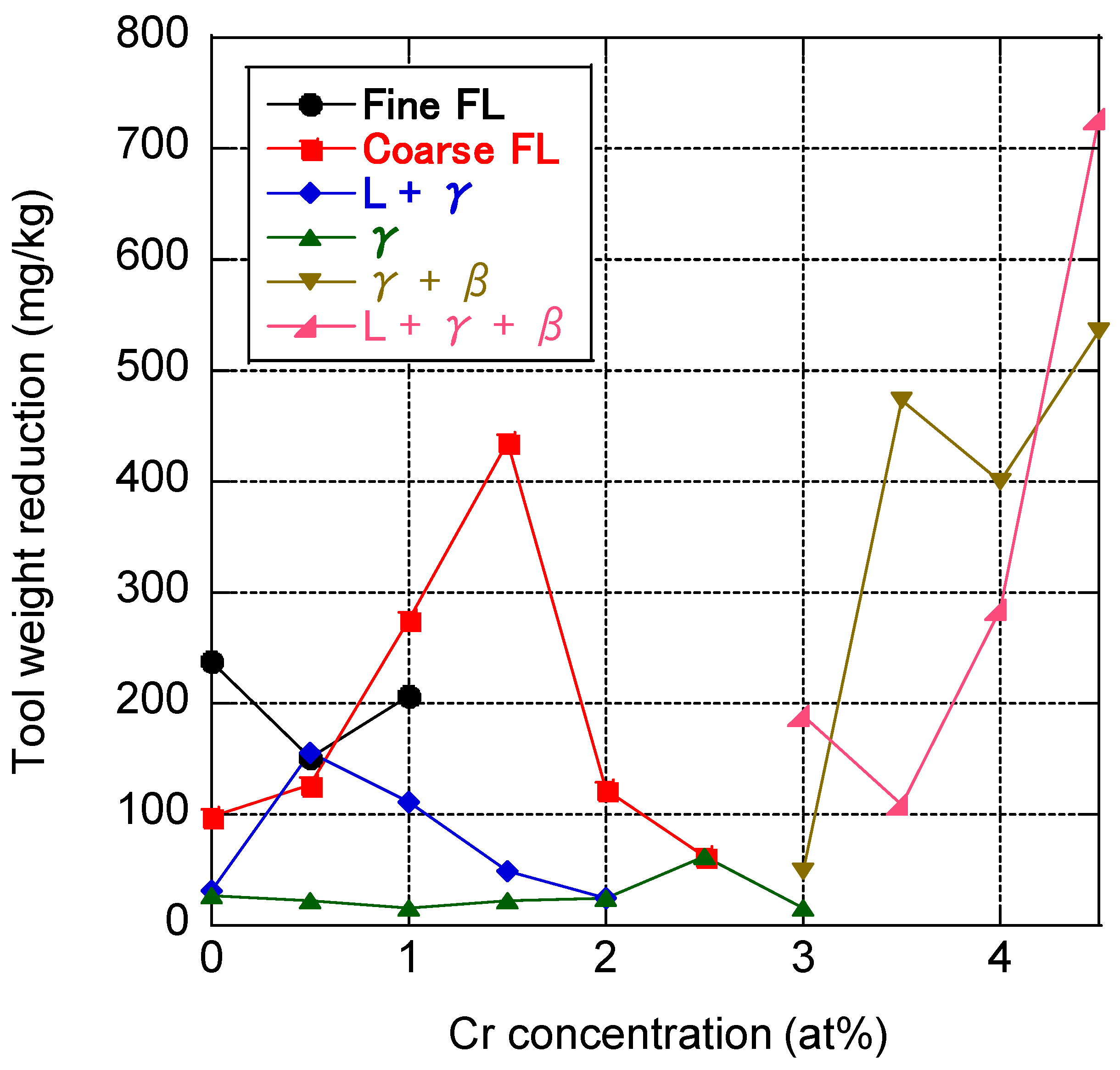
Excluding TiAl alloys currently used for rotating parts in jet engines, cast Ni-based superalloys are the materials with the lowest impact resistance. The room temperature Charpy absorbed energy of this material is at least 10–20 J/cm2 with notched specimens [27,28]. On the other hand, the maximum average absorbed energy obtained in this study was 12.2 J/cm2 (Ti-47.0Al-1.5Cr with Coarse FL structure) with non-notched specimens at room temperature, which is still inferior. However, as can be seen from the extreme difference in practical use between TiAl4822 and TNM alloy, a slight difference in impact resistance made a large difference in the actual usage environment. Therefore, the results of this study are expected to contribute greatly to improving the reliability of TiAl alloys for jet engine blades against impact fracture.

3.3. Machinability

Figure 6 illustrates examples of the appearance of the machined surface of each microstructure after the cutting tests. The alloy composition and heat-treatment conditions were the same as those of the samples illustrated in Figure 4. Numerous pullout defects, a common type of defect on the machined surfaces of TiAl alloys, were observed on the surfaces of samples of fine FL, coarse FL, γ + β, and L + γ + β. It is well known that many pullouts occur on the machined surfaces of FL-microstructure [29,30]. This study also confirmed this to be true for the γ + β and L + γ + β samples. In other words, the β phase has a negative influence on the occurrence of surface defects. Conversely, the surface of L + γ has minor defects, while none were observed in γ. The surface defects observed in the five microstructures can be suppressed by reducing the rotation speed, feed rate, and depth of cut; however, this increases the time required for machining work and leads to a higher production cost.
Figure 7 presents the relationship between the amount of tool wear and the concentration of Cr for each microstructure. The amount of tool wear was defined as the combined weight loss of the seven inserts before and after performing the cutting test per the weight of the sample removed. The results indicate that tool wear was significantly higher in the samples with higher Cr concentrations, especially in γ + β and L + γ + β. Since the amount of β phase increased with increasing Cr concentration, the β phase had a negative effect on tool wear as well as on the surface defects. In the other four microstructures without the β phase, γ exhibited the least amount of tool wear, followed by L + γ. Meanwhile, fine FL and coarse FL caused high amounts of tool wear. From these results, we determined γ as the being best microstructure in terms of both surface defects and tool wear, which are indicators of machinability, followed by L + γ; the rest of the microstructures underperformed.

3.4. Creep Strength and Comprehensive Evaluation

Figure 8 illustrates the creep curves of samples of each microstructure up to 1500 h at 725 °C in the 200 MPa creep test. The alloy composition and heat-treatment condition of each microstructure are the same as those shown in Figure 4. The results reveal that L + γ + β, γ + β, and γ had low creep strength. This is a commonly observed trend for these microstructures [31,32,33]. However, the other three microstructures had significantly higher creep strengths than the above, with fine FL having the highest.
Table 1 summarizes the results of the impact, machinability, and creep tests of each microstructure. From a practical point of view, each microstructure can be evaluated as follows:
Fine FL is defective in all aspects except creep strength. In other words, this microstructure is impractical for components of low-temperature applications such as jet engine last-stage turbine blades. Fine FL is considered beneficial for components used in high-temperature applications, such as turbochargers in passenger cars and last-stage turbine blades in gas turbines for power generation. However, the former application will gradually disappear in the future owing to the trend toward electric vehicles. On the other hand, for the latter application, the product size is very large (approximately 0.8 m), meaning that there are technical issues such as the development of new casting technology.
Coarse FL has poor machinability but superior impact resistance and creep strength. It is an optimal microstructure for jet engine blades and other critical applications if a significant increase in costs can be allowed. However, in reality, this is rarely the case. Therefore, except in special applications such as defense, it is impractical.
L + γ is a balanced microstructure with good overall properties. This microstructure can improve the impact resistance of jet engine blades, albeit at a somewhat higher cost.
γ is a microstructure with poor overall properties except for machinability. Currently, TiAl alloy blades in LEAP engine are produced from permanent mold-cast ingots of TiAl4822, produced by GfE Metalle und Materialien GmbH, Germany [16]. The blades are machined from this ingot after being subjected to hot isostatic pressing (HIP). The alloy composition and HIP conditions of this material are adjusted to possess an almost γ single-phase microstructure. In other words, improving machinability for cost reduction is presumably the prime concern for blade manufacturers. In this application, the low creep strength of the γ-microstructure does not cause structural weakness owing to the low design stress. However, this microstructure (γ) has the lowest impact resistance against high-speed collisions of debris, which are a concern. In previous operations, no evidence of impact fracture was found in TiAl4822, unlike in TNM alloys. However, the likely reason for this was that the equipment structure and operating environment prevented debris from passing from the engine’s interiors. Therefore, caution must be exercised when using it for other engines in different operating environments and structures, which may not prevent the collisions of debris.
Meanwhile, the γ + β and L + γ + β have poor overall properties and are impractical. Hence, the β phase is unnecessary for jet engine blades. In other words, although TiAl-forged material [34,35,36], which is premised to contain the β phase for improving forgeability, is still useful as materials for large-area plates [37] or large structural components [38] difficult to make via casting, its use for small-sized products that can be manufactured by casting is questionable.

4. Summary

The impact resistance and machinability of TiAl alloys have not been studied extensively. Nevertheless, these properties determine the reliability and the manufacturing costs of current TiAl alloy blades for jet engines. In this study, the effects of microstructure on these properties were investigated by using Ti–Al–Cr ternary alloys in the Charpy impact test at room temperature and 700 °C and in cutting tests using a face mill with cemented carbide tools. The results of the study are as follows:
  • Six types of typical microstructures of TiAl alloys, namely fine FL, coarse FL, L + γ, γ, γ + β, and L + γ + β, could be formed by varying the Al and Cr concentrations and heat-treatment conditions.
  • Impact resistance and machinability are each the exact opposite trend to the other, with coarse FL having the best impact resistance but poor machinability. Meanwhile, γ has the best machinability but the weakest impact resistance.
  • L + γ has more balanced overall properties, including creep strength, than the rest of the microstructures.
  • Almost all properties of γ + β and L + γ + β, including the β phase, were poor. This result suggests that the β phase is unnecessary for jet engine blades.
From a practical point of view, TiAl4822 blades currently being used in LEAP engine have an almost γ single-phase microstructure, this indicates that improving machinability to reduce costs is the prime concern for manufacturers. However, since this microstructure has the lowest impact resistance among all the microstructures, caution must be exercised when using it for other engines in different operating environments. On the other hand, the use of TiAl-forged materials for small-sized products that can be manufactured by casting is questionable, because the β phase, which is essential in TiAl-forged alloys, adversely affects all properties.

Funding

This research received no external funding.

Data Availability Statement

Not applicable.

Conflicts of Interest

The authors declare no conflict of interest.

References

  1. Noda, T. Application of cast gamma TiAl for automobiles. Intermetallics 1998, 6, 709–713. [Google Scholar] [CrossRef]
  2. Tetsui, T. Development of a TiAl turbocharger for passenger vehicles. Mater. Sci. Eng. A 2002, 329, 528–588. [Google Scholar] [CrossRef]
  3. Burtscher, M.; Klein, T.; Lindemann, J.; Lehmann, O.; Fellmann, H.; Güther, V.; Clemens, H.; Mayer, S. An advanced TiAl alloy for high-performance racing applications. Metals 2020, 13, 4720. [Google Scholar] [CrossRef] [PubMed]
  4. Perrut, M.; Caron, P.; Thomas, M.; Couret, A. High-temperature materials for aerospace applications: Ni-based superalloys and TiAl alloys. Comptes Rendus Phys. 2018, 19, 657–671. [Google Scholar] [CrossRef]
  5. Grange, M.; Raviart, J.L.; Thomas, M. Influence of microstructure on tensile and creep properties of a new castable TiAl-based alloy. Metall. Mater. Trans. A 2004, 35, 2087–2102. [Google Scholar] [CrossRef]
  6. Karthikeyan, S.; Mills, M.J. The role of microstructural stability on compression creep of fully lamellar g-TiAl alloys. Intermetallics 2002, 13, 985–992. [Google Scholar] [CrossRef]
  7. Kim, Y.-W.; Kim, S.-L. Effects of microstructure and C and Si additions on elevated temperature creep and fatigue of gamma TiAl. Intermetallics 2014, 53, 92–101. [Google Scholar] [CrossRef]
  8. Hénaff, G.; Gloanec, A.-L. Fatigue properties of TiAl alloys. Intermetallics 2005, 13, 543–558. [Google Scholar] [CrossRef]
  9. Shida, Y.; Anada, H. The effect of various ternary additives on the oxidation behavior of TiAl in high-temperature air. Oxid. Met. 1996, 45, 197–219. [Google Scholar] [CrossRef]
  10. Taniguchi, S.; Shibata, T. Influence of additional elements on the oxidation behavior of TiAl. Intermetallics 1996, 4, S85–S93. [Google Scholar] [CrossRef]
  11. Bartolotta, P.; Barrett, J.; Kelly, T.; Smashey, R. The use of cast Ti-48Al-2Cr-2Nb in jet engines. JOM 1997, 49, 48–50. [Google Scholar] [CrossRef]
  12. Bewlay, B.P.; Nag, S.; Suzuki, A.; Weimer, M.J. TiAl alloys in commercial aircraft engines. Mater. High Temp. 2016, 33, 549–559. [Google Scholar] [CrossRef]
  13. Habel, U.; Heutling, F.; Kunze, C.; Smarsly, W.; Das, G.; Clemens, H. Chapter 208, Forged intermetallic-TiAl-based alloy low-pressure turbine blade in the geared turbofan. In Proceedings of the 13th World Conference on Titanium, Manchester Grand Hyatt, San Diego, CA, USA, 16–20 August 2015; Vasisht Venkatesh, V., Pilchak, A.L., Allison, J., Ankem, S.E., Boyer, R., Christodoulou, J., Fraser, H.L., Imam, M.A., Kosaka, Y., Rack, H.J., et al., Eds.; Wiley: Hoboken, NJ, USA, 2016; pp. 1223–1227. [Google Scholar]
  14. Clemens, H.; Mayer, S. Intermetallic titanium aluminides in aerospace applications—Processing, microstructure and properties. Mater. High Temp. 2016, 33, 560–570. [Google Scholar] [CrossRef]
  15. Flightglobal.com. Available online: https://www.flightglobal.com/engines/faa-orders-pw1100g-low-pressure-turbine-blade-replacement/135575.article (accessed on 16 May 2023).
  16. Güther, V.; Allen, M.; Klose, J.; Clemens, H. Metallurgical processing of titanium aluminides on industrial scale. Intermetallics 2018, 103, 12–22. [Google Scholar] [CrossRef]
  17. Tetsui, T. Selection of additive elements focusing on impact resistance in practical TiAl cast alloys. Metals 2022, 12, 544. [Google Scholar] [CrossRef]
  18. Tetsui, T. Impact resistance of commercially applied TiAl alloys and simple-composition TiAl alloys at various temperatures. Metals 2022, 12, 2003. [Google Scholar] [CrossRef]
  19. Tetsui, T.; Kobayashi, T.; Ueno, T.; Harada, H. Consideration of the influence of contamination from oxide crucibles on TiAl cast material, and the possibility of achieving low-purity TiAl precision cast turbine wheels. Intermetallics 2012, 31, 274–281. [Google Scholar] [CrossRef]
  20. Kim, Y.-W. Effects of microstructure on the deformation and fracture of γ-TiAl. Mater. Sci. Eng. 1995, 192–193, 519–533. [Google Scholar] [CrossRef]
  21. Harding, T.S.; Jones, J.W. Effect of foreign object damage on the fatigue strength of an XDTM-TiAl alloy. Scr. Mater. 2000, 43, 631–636. [Google Scholar] [CrossRef] [Green Version]
  22. Aspinwall, D.K.; Dewes, R.C.; Manfle, A.L. The machining of γ-TiAl intermetallic alloys. CIRP Ann. J. Manuf. Technol. 2000, 54, 99–104. [Google Scholar] [CrossRef]
  23. Castellanos, S.D.; Cavaleiro, A.J.; de Jesus, A.M.P.; Neto, R.; Alves, J.L. Machinability of titanium aluminides: A review. J. Mater Des. Appl. 2019, 233, 426–451. [Google Scholar] [CrossRef]
  24. Aspinwall, D.K.; Mantle, A.L.; Chan, W.K.; Hood, R.; Soo, S.L. Cutting temperatures when ball nose end milling γ-TiAl intermetallic alloys. CIRP Ann. Manuf. Technol. 2013, 62, 75–78. [Google Scholar] [CrossRef] [Green Version]
  25. Priarone, P.C.; Rizzuti, S.; Rotella, G.; Settineri, L. Tool wear and surface quality in milling of a gamma-TiAl intermetallic. Int. J. Adv. Manuf. Technol. 2012, 61, 25–33. [Google Scholar] [CrossRef] [Green Version]
  26. Clemens, H.; Mayer, S. Design, processing, microstructure, properties, and applications of advanced intermetallic TiAl alloys. Adv. Eng. Mater. 2013, 15, 191–215. [Google Scholar] [CrossRef]
  27. Bouse, G.K. Impact and fracture toughness of investment cast, plasma sprayed, and wrought alloy 718. In Superalloys 718, 625 and Derivatives; Loria, E.A., Ed.; The Minerals, Metals & Materials Society, 1991; pp. 287–296. [Google Scholar]
  28. Zýka, J.; Hlous, J.; Podhorná, B.; Dobrovská, J.; Hrbáček, K. Heat treatment and properties of nickel superalloy 718plus. In Proceedings of the 19th International Conference on Metallurgy and Materials, Rožnov pod Radhoštěm, Czech Republic, 18–20 May 2010. [Google Scholar]
  29. Hood, R.; Aspinwall, D.K.; Sage, C.; Voice, W. High speed ball nose end milling of γ-TiAl alloys. Intermetallics 2013, 32, 284–291. [Google Scholar] [CrossRef]
  30. Xi, X.; Ding, W.; Wu, Z.; Anggei, L. Performance evaluation of creep feed grinding of γ-TiAl intermetallics with electroplated diamond wheels. Chin. J. Aeronaut. 2021, 34, 100–109. [Google Scholar] [CrossRef]
  31. Schwaighofer, E.; Clemens, H.; Mayer, S.; Lindemann, J.; Klose, J.; Smarsly, W.; Güther, V. Microstructural design and mechanical properties of a cast and heat treated intermetallic multi-phase γ-TiAl based alloy. Intermetallics 2014, 44, 128–140. [Google Scholar] [CrossRef]
  32. Wang, J.G.; Nieh, T.G. Creep of a beta phase-containing TiAl alloy. Intermetallics 2000, 8, 737–748. [Google Scholar] [CrossRef]
  33. Xia, Z.; Liu, R.; Shen, Y.; Mohammed, A.; Jia, Q.; Cui, Y.; Yang, R. Creep properties of Ti–48Al–2Cr–2Nb alloy having similarly oriented lamellae with fine lamellar spacing. Mater. Sci. Eng. A 2022, 861, 144362. [Google Scholar] [CrossRef]
  34. Xu, H.; Li, X.; Xing, W.; Shu, L.; Ma, Y.; Liu, K. Processing map and hot working mechanism of as-cast Ti–42Al–5Mn alloy. Adv. Eng. Mater. 2018, 20, 1701059. [Google Scholar] [CrossRef]
  35. Janschek, P. Wrought TiAl blades. Mater. Today Proc. 2015, 2, S92–S97. [Google Scholar] [CrossRef]
  36. Zhao, X.; Wei, J.; Niu, H.; Cao, S.; Du, Z.; Jia, Y.; Yao, H.; Zhang, Z.; Han, J. Mechanical and Physical Characterizations of a Three-Phase TiAl Alloy during Near Isothermal Forging. Crystals 2022, 12, 1391. [Google Scholar] [CrossRef]
  37. Jiang, H.; Zeng, S.; Zhao, A.; Ding, X.; Dong, P. Hot deformation behavior of β phase containing γ-TiAl alloy. Mater. Sci. Eng. A 2016, 661, 160–167. [Google Scholar] [CrossRef]
  38. Tetsui, T. Practical use of hot-forged-type Ti-42Al-5Mn and various recent improvements. Metals 2021, 11, 1361. [Google Scholar] [CrossRef]
Figure 1. Schematic of the split metal mold and the shape of the cast material.
Metals 13 01235 g001
Figure 2. Milling cutter and inserts used in the cutting test by face mill, and typical wear area of an insert and the method of tool wear measurement.
Metals 13 01235 g002
Figure 3. Distinction of the microstructures formed under the four conditions of heat treatment of each Ti–Al–Cr ternary alloy by color coding.
Metals 13 01235 g003
Figure 4. Backscattered electron images showing the microstructure of the Ti–Al–Cr ternary alloys: (a) Fine FL, Ti-45.0Al-0.5Cr, 1200 °C/5 h/FC, (b) Coarse FL, Ti-47.0Al-1.0Cr, 1400 °C/1 h/FC, (c) L + γ, Ti-47.0Al-1.0Cr, 1300 °C/2 h/FC, (d) γ, Ti-48.0Al-1.0Cr, 1100 °C/10 h/FC, (e) γ + β, Ti-47.0Al-3.5Cr, 1200 °C/5 h/FC, (f) L + γ + β, Ti-46.0Al-3.5Cr, 1400 °C/1 h/FC.
Metals 13 01235 g004
Figure 5. Relationship between Charpy absorbed energy and Cr concentration for each microstructure; (a) fine FL, (b) coarse FL, (c) L + γ, (d) γ, (e) γ + β, and (f) L + γ + β at room temperature and 700 °C.
Metals 13 01235 g005
Figure 6. Appearance of machined surface of each microstructure after cutting test: (a) fine FL, (b) coarse FL, (c) L + γ, (d) γ, (e) γ + β, (f) L + γ + β.
Metals 13 01235 g006
Figure 7. Relationship between amount of tool wear and Cr concentration for samples with each microstructure.
Metals 13 01235 g007
Figure 8. Creep curves of samples of each microstructure in a 200 MPa creep test at 725 °C.
Metals 13 01235 g008
Table 1. Comprehensive evaluation of each microstructure.
Impact ResistanceMachinabilityCreep Strength
RT700 °CMachined SurfaceTool Wear
Fine FLPoorPoorPoorPoorExcellent
Coarse FLExcellentExcellentPoorPoorAverage
γ + LAverageExcellentAverageAverageAverage
γPoorPoorExcellentExcellentPoor
γ + βPoorPoorPoorPoorPoor
L + γ + βPoorAveragePoorPoorPoor
Disclaimer/Publisher’s Note: The statements, opinions and data contained in all publications are solely those of the individual author(s) and contributor(s) and not of MDPI and/or the editor(s). MDPI and/or the editor(s) disclaim responsibility for any injury to people or property resulting from any ideas, methods, instructions or products referred to in the content.

