1. Introduction
Molybdenum possesses both high physical and mechanical properties, such as good structural stability, thermal conductivity, and high strength at high temperatures [
1]. Its highly stable body-centered cubic (BCC) structure makes multi-strengthening methods possible in molybdenum alloys. The effective improvement of strength and creep resistance at high temperatures could be obtained via solution strengthening (Zr, Ti [
2], Nb, W [
3], Si [
4], and B [
5]), dispersion strengthening (MoTiC [
6], HfC [
7], La
2O
3 [
8,
9], WC [
10], ZrC [
11] et al.), and the combination of these two strengthening methods [
12]. High mechanical properties at high temperatures have been achieved in some Mo alloys, such as ZrC-strengthened Mo alloys [
11]. Thermal stability is a key factor to determine the service life because Mo alloys are often used in high temperature environments. Thermal stability can also be successfully approached and, importantly, guided by theoretical works, especially by ab initio molecular dynamics (AIMD) [
13,
14]. Researchers employ AIMD to successfully deal with thermal stability and mechanical properties in 2D materials.
Although a large amount of research has been conducted, the structural stability and reliability of Mo alloys at high temperatures for a pretty long time are still doubtful. To obtain a high requirement of stability, single crystals for refractory alloys are becoming the most potential choices in the future. Among lots of refractory alloys, MoNb single crystals possess excellent structural stability and mechanical properties at high temperatures [
15]. The high preference for Mo alloy single crystals is attributed to the relatively low stored energy that is caused by the low density of dislocations and small-angle grain boundaries [
16]. As a typical domestic refractory system, the microstructures and mechanical properties of MoNb single crystals have been widely investigated [
17,
18,
19]. Slip behavior and dislocation arrangements are carefully justified under compression at room temperature [
17]. For compression at high temperatures, structural stability in MoNb single crystals rises as the Nb content increases [
18]. What is more, researchers have compressively compared the difference in mechanical responses between single crystals and poly-crystals [
3].
Although they contain excellent properties at high temperatures, the mechanical properties of Mo single crystals, especially the ductility at room temperature, still need to be improved. Among many methods, one of the most effective ways to enhance mechanical properties is adding Rhenium to Mo alloys [
19]. Considering the high cost of Rhenium, thermal annealing is another usual way to enhance the mechanical properties [
20,
21,
22]. Lowry et al. showed that the theoretical strength of Mo alloys with defect-free crystals is obtained via proper heat treatment [
20]. In Yang et al.’s results, dislocations are from excess vacancy during the annealing treatment and play important roles for precipitates in Mo-12Si-8.5B alloys [
21]. However, in Hiraoka’s results, the embrittlement after annealing at 1500 °C is mainly due to the proceeding of second-phase precipitation followed by a substantial hardening in Mo-40% Ru alloy [
22].
Here, firstly, the structural evolution and mechanical properties of Mo alloys’ single crystals via adding Nb are investigated. Secondly, the effect of thermal annealing on the mechanical properties of MoNb single crystals is considered and discussed. Mo and MoNb alloys single crystals are prepared via the electron beam zone-melting method. The annealing temperature is in the range of 1100 °C to 1700 °C. The annealing time is maintained for 2 h to ensure uniform heating. The tensile tests at room temperature and structural evolutions before and after annealing are carefully investigated in this research, in order to evaluate the influence of thermal annealing on the mechanical properties of MoNb alloys’ single crystals.
3. Results
XRD patterns for casted Mo, Mo3Nb, and Mo6Nb are shown in
Figure 1a. The 2θ ranges from 20° to 120°. Only 222 peaks are detected at ~117° (an extinction of light occurs at 111 orientation). Such features not only justify the growing direction is 111, but also prove the single crystal body-centered cubic (BCC) structure for all samples. Although the lattice misfit is enhanced as the Nb content increases, the structural stability is maintained after adding 6 at.% content.
Figure 1b,c, respectively, show the microstructural evolution of Mo3Nb and Mo6Nb after thermal annealing at 1100 °C, 1300 °C, 1500 °C, and 1700 °C for 2 h. Still, only 222 peaks are detected at ~117° in all annealed samples. The same features of casted and annealed Mo3Nb and Mo6Nb suggest no recrystallization occurs, which means a high thermal stability (≤1700 °C) of Mo and MoNb single crystals.
To observe the evolution of the low-angle grain boundary after annealing, metallographic photos of Mo3Nb single crystals were taken and are shown in
Figure 2. The reticular wave lines on the surface of MoNb single crystals are known as the low-angle grain boundary.
Figure 2a shows the distribution of the low-angle grain boundary for as-casted Mo3Nb single crystals. Low density in the center part and a relatively higher density at the edge were observed, which is consistent with the thermal diffusion direction. The density of the low-angle grain boundary in Mo3Nb rises after annealing at 1100 °C, as shown in
Figure 2b. Then, the density of the low-angle grain boundary drops after annealing at high temperatures, as shown in
Figure 2c,d. As shown in
Figure 2c, the low-angle grain boundary in the center part dramatically decreases. For the samples after 1700 °C annealing, nearly all of the wave lines are absent, as shown in
Figure 2d.
Figure 3 shows the evolution of the low-angle grain boundary of Mo6Nb single crystals before and after annealing. Comparing with as-casted Mo3Nb, the density of the low-angle grain boundary obviously elevates in as-casted Mo6Nb, as shown in
Figure 2a and
Figure 3a. This is consistent with the higher lattice misfit in Mo6Nb than in Mo3Nb single crystals. The low-angle grain boundary density decreases as the annealing temperature increases, as shown in
Figure 3a–d. After 1700 °C annealing, no low-angle grain boundary was detected in Mo6Nb, as shown in
Figure 3d, which is the same as Mo3Nb.
These results in
Figure 2 and
Figure 3 mean that both Nb content and annealing temperature influence the microstructure of MoNb single crystals. The main difference between Mo3Nb and Mo6Nb is the structural evolution after 1300 °C annealing, which may relate to the zone-melting process. In annealing tests at high temperatures (1500 °C and 1700 °C), the low-angle grain boundary density drops in both Mo3Nb and Mo6Nb, which may be contributed to by a diffusion-induced defect evolution.
Figure 4 shows the tensile results of Mo and MoNb single crystals.
Figure 4a–c are true strain-true stress curves for Mo, Mo3Nb, and Mo6Nb, respectively. Three tests were given for every group to ensure tensile results. Mo single crystals yield at nearly 300 MPa. Then, true stress continues to rise as true strain increases. The maximum stress reaches 550 MPa at true strain ~ 5%, as shown in
Figure 4a. Mo3Nb single crystals yield at ~400 MPa. A small stress drop occurs after yield and the maximum stress reaches 600 MPa, as shown in
Figure 4b. The yield point in Mo6Nb single crystals is 450 MPa, which is nearly the same as the maximum stress, as shown in
Figure 4c.
Figure 4d shows representative Mo, Mo3Nb, and Mo6Nb curves, in order to compare different deformation features. No obvious difference was observed among the three curves before yield, suggesting a small content of Nb addition has little influence on the elastic contacts of Mo. Yield happens in Mo single crystals first. Then, true stress increases slowly as the strain continues, as shown in
Figure 4a. For Mo3Nb single crystals, true stress drops ~20 MPa at 1% strain after yield, followed by a gentle rise during subsequent loading, as shown in
Figure 4b. Yield enhances as the Nb content increases. Mo6Nb possesses higher strength (~450 MPa) than Mo3Nb and Mo. Furthermore, the stress in Mo6Nb maintains at a relatively stable level until failure, as shown in
Figure 4c,f, which means a stable flow and dislocation movement. Severe work hardening occurs in Mo3Nb at true strain ranges from 1.5% to ~5%, and then, softening occurs and stress drops quickly until failure, as shown in
Figure 4e. The true stress maintains a stable value after yield to fracture, which suggests a relatively uniform plastic flow. In summary, the addition of Nb not only enhances the strength of Mo but also improves the stability of mechanical properties.
Representative true stress-true strain curves of Mo3Nb and Mo6Nb after annealing are shown in
Figure 5a,b, respectively. Thermal annealing has little effect on the deformation features, such as elastic to plastic regions and work-hardening behavior. An outstanding behavior in Mo3Nb single crystals is the stress drop after yield, which disappears after annealing at 1700 °C. Such behavior is related to dislocation de-pinned at the yield point. Annealing at 1700 °C makes solute atoms distribute more uniformly than as-casted Mo3Nb single crystals.
What is more, strength and elongation change a lot after annealing.
Figure 5c,d shows the evolution of strength and elongation in Mo3Nb and Mo6Nb as the annealing temperature rises, respectively. Comparing with the as-casted sample (yield strength ~410 MPa and elongation 10.9%), the yield strength in Mo3Nb does not change so much after annealing. For example, the yield strength is 405 MPa after 1700 °C annealing. Elongation, however, enhances notably after annealing, especially at 1300 °C annealing. The yield stress in Mo6Nb single crystals decreases continuously as the annealing temperature rises. The strength of Mo6Nb decreases from ~475 MPa at the 1100 °C annealed sample to ~425 MPa at the 1700 °C annealed sample. Meanwhile, the elongation of Mo6Nb increases from ~10% at the 1100 °C annealed sample to ~17% at the 1700 °C annealed sample.
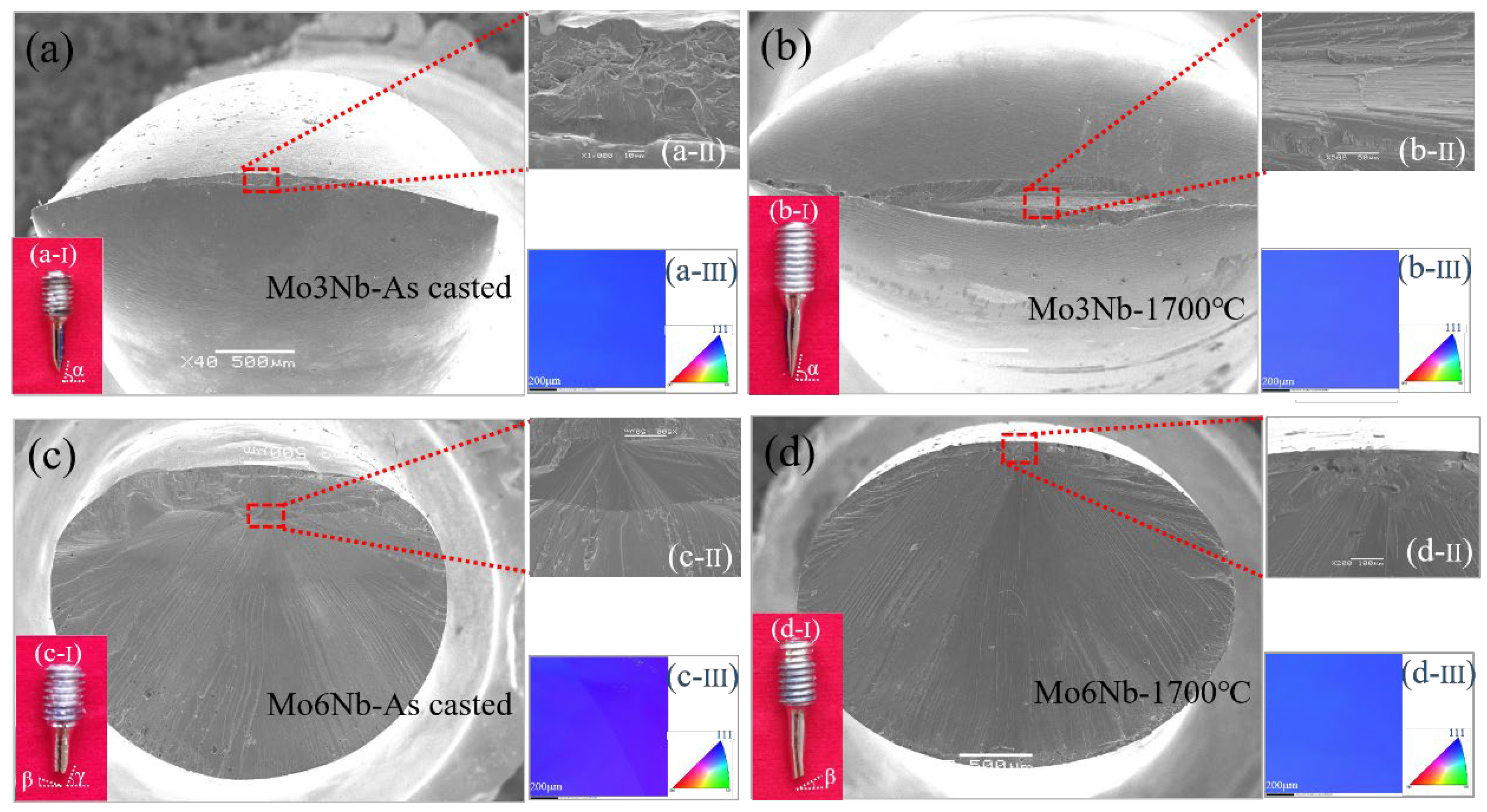
Figure 6 shows microscopes of fracture surfaces after tension. The fracture surface section in Mo3Nb looks like a thin line at the edge. The middle part shows river patterns that suggest inhomogeneous deformation, as shown in the insert (a-I). Such a kind of feature is caused by severe shrinkage in one direction, but relatively small shrinkage in another direction. In
Figure 6b, the 1700 °C annealed Mo3Nb behaves the same fracture mode with the as-casted Mo3Nb. Still, some defects, such as holes, were detected near the middle part of the fracture section. The area of the fracture surface is larger in the 1700 °C annealed Mo6Nb than in the as-casted one.
Distinguishing from the fracture feature in Mo3Nb, the fracture surface of the as-casted Mo6Nb is like an oval, as shown in
Figure 6c. That means the difference between the shrinkage of the two vertical directions in Mo6Nb is much smaller than Mo3Nb. It is noted that those river patterns extend from a small region near the surface with some holes around it, as shown in
Figure 6d. In general, as-casted Mo6Nb shows a similar fracture feature in the 1700 °C annealed sample, except that the river patterns initiate in the inner part. The fracture angles are signed as α in the insert of
Figure 6a,b, and are signed as β and γ in the insert of
Figure 6c,d. The fracture angle still means there is a different deformation mode between Mo3Nb and Mo6Nb single crystals.
The inserts of
Figure 6(a-III,b-III,c-III,d-III) are EBSD results of as-casted Mo3Nb, 1700 °C annealed Mo3Nb, as-casted Mo6Nb, and 1700 °C annealed Mo6Nb, respectively. All deformed samples only show the 111 texture, and no recrystallization is observed. Therefore, Mo3Nb and Mo6Nb single crystals possess good mechanical properties and high structural stability during tension at room temperature. The ductility of Mo3Nb and Mo6Nb are both enhanced to some extent after thermal annealing.
Figure 7 shows TEM figures of deformed samples. All images are observed along the 111 zone axis. Many tangled dislocation lines are observed in the deformed samples. There are some differences in the density of dislocation. Firstly, the density of dislocation in the 1700 °C annealed Mo3Nb is less than in the as-casted Mo3Nb. The width between the two groups of tangled dislocations in the as-casted Mo3Nb (W
1 in
Figure 7a) is thinner than in the 1700 °C annealed Mo3Nb (W
2 in
Figure 7b). Such a trend means some dislocations have been removed via annealing at 1700 °C. Secondly, the dislocation density in the 1700 °C annealed Mo6Nb is less than in the 1700 °C annealed Mo3Nb, which may lead to a higher strength in Mo6Nb than Mo3Nb.
Figure 7d,g shows the magnifications of the dislocation feature in
Figure 7a.
in
Figure 7d,g are
and 110, respectively. Those white dotted lines in
Figure 7d represent dislocation lines that are visible in
Figure 7d, but invisible in
Figure 7g. Thus, those dislocations in
Figure 7d should have
. There are still some tangled dislocations that have not been justified. The magnifications of the dislocation feature in
Figure 7a are shown in
Figure 7e,h. Two long dislocations signed as dotted lines have
The corresponding dotted lines in
Figure 7f,i still have
Less tangled dislocation is observed in the 1700 °C annealed Mo6Nb than in the 1700 °C annealed Mo3Nb, which is ensured via
Figure 7e,f.
Figure 8 shows the line-scanning EDS data along dislocations in the as-casted Mo3Nb, the 1700 °C annealed Mo3Nb, the as-casted Mo6Nb, and the 1700 °C annealed Mo6Nb. The white lines in the middle of the TEM images show the positions of the dislocations. There is no obvious fluctuation in Mo in all of the samples, as shown in the red figures in
Figure 8. The fluctuation in Re, however, is less severe in the as-casted Mo3Nb than in Mo6Nb, as shown in
Figure 8a,c. After annealing at 1700 °C, Nb fluctuates smoothly in both Mo3Nb and Mo6Nb, meaning Nb distributes more uniformly after 1700 °C annealing. In detail, the dislocation in the as-casted Mo3Nb has a bit concentration of Nb, which is eliminated after annealing at 1700 °C, as shown in
Figure 8a,b. In the as-casted Mo6Nb, the Nb content around the dislocation is a little higher than the matrix. Similar to Mo3Nb, the Nb concentration in dislocation is eliminated to a large extent after annealing. Therefore, thermal annealing makes the microstructure more homogeneous than the as-casted Mo-Nb single crystals.
4. Discussion
As-casted Mo3Nb and Mo6Nb have different fracture directions along with loading directions, as shown α and α + β in inserts (a-I) and (c-I) in
Figure 6. α, β, and γ are ~70°, ~20°, and ~55°, respectively. The loading directions are all 111 in the above-mentioned results, and
is justified via TEM figures in
Figure 7. Furthermore, the dislocations that activated at room temperature in Mo are always screw features [
23]. Thus, the slip directions in both Mo3Nb and Mo6Nb single crystals are the same with
. Those slip systems are likely to be (110)<
>, (011)<
>, (121)<
>, (
)<
>, and (
)<
>. The {123}<111> slip systems are not considered here because those are rarely observed in BCC metals at room temperature [
24,
25]. Combining the possible systems and fracture features (α, β, and γ) in
Figure 6, plastic deformation in the as-casted and 1700 ℃ annealed Mo3Nb should be dominated by various slip systems because only one group of slip systems could not have α. In the as-casted Mo6Nb, as shown in
Figure 6c, the fracture surface with β + γ occurs, which contributed to the slip in both the (121) <
> and (110)<
> systems. After annealing at 1700 °C, only the fracture surface with β was observed, i.e., the slip in the (121) <
> system was constricted. The addition of Nb changes the preference of the slip system. The (110)<
> system is preferred in MoNb single crystal with low Nb content. In high Nb content MoNb single crystals, however, the (121) <
> system is preferred at room temperature tensile tests with loading direction 111. In short, the critical resolved shear stress in the (110)<
> system is enhanced by increasing Nb, which could be discussed further in future work.
As shown in
Figure 4, deformation features are distinguishing among Mo, Mo3Nb, and Mo6Nb single crystals. The deformation features in Mo3Nb are nearly the same as in the Mo single crystals, as shown in
Figure 4a,b, except for a stress drop after yield in Mo3Nb. Such a difference may be contributed to by the dislocation extending unstably after yield in Mo3Nb, i.e., the activation energy for dislocation extension is lower than for dislocation nucleation in Mo3Nb. What is more, the stress drop may be caused by the content fluctuation in as-casted Mo3Nb single crystals, as shown in
Figure 8a. Dislocations are pinned by Nb atoms in the elastic deformation region. Then, dislocations de-pin and move when yield happens. A stress drop occurs when solute atoms distribute un-uniformly.
Work-hardening behaviors are nearly the same in Mo3Nb and Mo single crystals. Work-hardening in BCC metals at room temperature is mainly attributed to dislocation substructure [
26], collective motion, and the interaction of dislocations [
27]. As shown in the insert
Figure 6(a-I), severe necking happens in Mo3Nb single crystals with a thin line in the fracture surface. As the Nb content rises, the work-hardening is much less (~0) in Mo6Nb than in Mo3Nb, as shown in
Figure 4f. The yield stress is similar to the ultimate tensile strength of Mo6Nb, meaning a relatively stable dislocation extension at room temperature. Further research is necessary to reveal the effect of Nb on nucleation and the extension of dislocations in MoNb single crystals.
By adding Nb to Mo, the yield strength increases from ~250 MPa in Mo to ~450 MPa in Mo6Nb single crystals. Meanwhile, the ductility of as-casted single crystals does not change so much by adding Nb. For example, Mo single crystals have a ductility of ~10%, which is similar to Mo3Nb and Mo6Nb, which may be attributed to the same crystal growth methods and the distribution of residual stress and structural defects.
After annealing, the ductility in Mo3Nb and Mo6Nb are both effectively enhanced. For example, the ductility in the 1700 °C annealed Mo6Nb is enhanced to ~17%, which is much higher than ~10%. As shown in
Figure 8, Nb distributes more uniformly after annealing at 1700 °C than the as-casted sample, meaning residual stress and structural defects are removed to a large extent. The unstable propagation of cracks may be delayed as growing stress relaxes after annealing.
One noted point is that strength in Mo3Nb single crystals drops from 420 MPa to 380 MPa, whereas the elongation visibly enhanced from 9% to 15.5% after annealing at 1300 °C, as shown in
Figure 5c. Combining the stress drop behavior and content distribution of as-casted Mo3Nb single crystals, Nb atoms distribute less uniformly in as-casted Mo3Nb than in as-casted Mo6Nb. High growth stress concentration leads to relatively high strength and low elongation in as-casted Mo3Nb. It may be hard for growth stress to totally relax when annealing at 1100 °C. Growth stress may be totally relaxed due to enhanced atomic diffusion when annealing at a proper temperature (1300 °C). In this situation, elongation/strength effectively enhances/decreases. As the annealing temperature continually rises (1500 °C and 1700 °C), the low-angle grain boundary further eliminates due to fast atomic diffusion. As shown in
Figure 7b, dislocation density decreases after annealing at 1700 °C, which causes the strength to further rise. Thus, choosing a proper annealing temperature is vital to determine the evolution of strength and ductility.

