Article

Numerical Simulation of Turbulence Intensity of an Acid Solution during the Strip Steel Pickling Process

1
National Engineering Research Center for Equipment and Technology of Cold Strip Rolling, Yanshan University, Qinhuangdao 066004, China
2
State Key Laboratory of Metastable Materials Science and Technology, Yanshan University, Qinhuangdao 066004, China
*
Author to whom correspondence should be addressed.
Metals 2023, 13(7), 1293; https://doi.org/10.3390/met13071293
Submission received: 24 May 2023 / Revised: 2 July 2023 / Accepted: 12 July 2023 / Published: 19 July 2023
(This article belongs to the Special Issue Metal Plastic Deformation and Forming)

Abstract

:
This study aims to enhance the efficiency of pickling processes by investigating the impact of strip speed and acid flow rate on the turbulence of the acid solution within the pickling tank. The research quantitatively evaluates the flow field state and distribution of acid temperature within the pickling tank. Through finite element simulation, factors such as jet velocity, strip motion velocity, and acid temperature are considered to determine the turbulence intensity, turbulent kinetic energy, convective heat transfer coefficient, and average temperature of the near-wall layer of the strip surface under the oblique jet. This analysis considers the effects of these parameters on the flow field within the pickling tank. Furthermore, simulations are conducted to assess the turbulence intensity of the acid solution under various conditions. The study reveals that the intake flow rate has a substantial influence on turbulence and temperature rise at the strip exit and inlet, albeit less so, within the acid tank itself. However, an increase in strip speed notably impacts the turbulence within the center of the acid tank. These findings are invaluable for regulating the pickling process and maintaining optimal strip surface quality in industrial production settings.

1. Introduction

The surface of the finished hot-rolled strip typically possesses an oxide layer that must be eliminated prior to cold rolling, ensuring the desired product quality for subsequent processes. However, incomplete pickling often leads to the presence of residual Fe2SiO4 or FeO on the strip’s surface, resulting in a chromatic defect, as depicted in Figure 1. Figure 1a shows the overall picture of color difference defects on the strip steel, and Figure 1b shows the color difference defects on the surface of the strip steel observed at close range. Consequently, extensive research is vital to understanding the factors influencing the efficacy of the pickling process. This paper focuses on a widely adopted pickling technique known as shallow tank turbulence pickling, which is employed in the pickling tank discussed herein. This technique is distinguished by its favorable pickling effect, low generation of waste acid, cost-effective pickling equipment, and commendable unit performance [1,2,3,4]. The pickling process area typically encompasses three pickling tanks, stretching and straightening equipment, and other associated machinery, as illustrated in Figure 2.
Enhancing the efficiency of pickling processes requires consideration of various variables. However, when the incoming material, acid temperature, and concentration are known, the most practical and cost-effective approach to improving pickling efficiency is to increase the heat transfer efficiency between the strip’s contact surface and the acid turbulence [5,6,7,8]. Turbulent flow occurs when a fluid undergoes constant changes in speed and direction of motion, accompanied by upward and downward pulsations that significantly enhance heat energy transfer [9,10,11]. By employing turbulent flow technology in the pickling line, the acid on the strip’s surface is continuously refreshed, thereby accelerating the reaction between the iron oxide and acid and reducing pickling time by half.
The Reynolds number (Re) serves as a parameter to determine the onset of turbulent flow; when Re exceeds 4000, turbulent conditions are considered to be present [12]. Increased fluid velocity leads to improved convective heat transfer coefficients and thermal conductivity. In this study, turbulence intensity and turbulent kinetic energy serve as indicators of the level of turbulence. Elevated fluid velocity enhances both thermal conductivity and the convective heat transfer coefficient. As the strip’s speed and relative velocity between the fluid and the strip increase, both the convective heat transfer coefficient and reactivity are heightened.
To assess the effects of incident flow rate and strip motion speed in the three-dimensional turbulent pickling tank, a finite element simulation is employed in this research. The simulation flow is depicted in Figure 3 below, enabling the determination of the turbulent intensity, turbulent kinetic energy, convective heat transfer coefficient, and temperature distribution on the strip surface.
In order to effectively model the acid turbulence occurring during the pickling of strip steel, research primarily focuses on two approaches utilizing finite element methods. Firstly, three-dimensional finite element simulations of fluids are employed. Secondly, investigations are conducted to understand the impact of pickling process parameters on pickling effectiveness [13]. A comprehensive literature search yielded relevant studies that contributed to the investigation of this research.
In the study of three-dimensional finite element simulation of fluids, O’Donovan, TS, et al. [14] performed an experimental analysis of heat transfer in a three-dimensional finite element modeling study. They specifically examined heat transfer to an obliquely impinging air jet. The study determined the distribution of the mean and fluctuation components of surface heat transfer. Another study conducted by Yang, Yt, et al. [15] focused on three-dimensional numerical modeling of inclined jet fluid flow and heat transfer properties of a cross-flow impinging heated plate.
Klaus and Pielsticker [16] employed numerical simulation to simulate the impact of jet beam side spray flow on acid dispersion in a turbulent pickling tank. Their study aimed to understand the behavior of acid dispersion under these conditions. Dhamodaran, M. et al. [17] proposed a fundamental and precise method for investigating the numerical analysis of fluid flow and heat transfer in a channel, offering valuable insights in this domain.
Alves, MA, et al. [18] presented benchmark flows used in computational rheology to assess the performance of numerical methods, specifically focusing on the simulation of viscoelastic fluid flow described by continuous horizontal differential principal equations. Ye, T., et al. [19] provided a review of boundary treatment algorithms for free surface or multiphase interfaces of complex fluids, offering valuable suggestions for smooth particle hydrodynamics (SPH) modeling of complex fluid flows. Shadloo, MS, et al. [20] outlined the purpose of using smooth particle hydrodynamics (SPH) methods in industrial settings and discussed their applicability and limitations, providing broad insights into their usage. These relevant studies contribute to the understanding and development of research on acid turbulence modeling during the pickling of strip steel, utilizing finite element approaches. Asbar et al. [21] used the finite element method to analyze the stress on the nozzle during the liquid release process of storage containers. Zhao, Jinghua, et al. [22] studied the formation and diffusion trajectory of scum on the zinc liquid during the hot dip galvanizing process of strip steel using fluid numerical simulation.
In a related investigation on pickling efficiency, He, F., et al. [23] developed a soft measurement method for acid concentration using a cluster analysis approach. The method incorporated process characteristics such as differential pressure, conductivity, and temperature. Gines, MJL, et al. [24] conducted laboratory experiments to examine the pickling duration of 1.8 mm hot-rolled steel sheets under various process conditions.
Kalasin, NN, et al. [25] investigated the dissolution rate of scales on hot-rolled steel strips made from continuous cast slabs and the time required for complete dissolution through pickling tests. To simulate the motion of an actual strip, Peng, JG, et al. [26] employed a rotating disk electrode to study the pickling performance of iron oxide on the surface of 2205 duplex stainless steel hot-rolled strips in a sulfuric acid electrolyte.
Liu, XJ, et al. [27] aimed to comprehend the mechanism of black band defects on the surface of hot-rolled silicon steel following pickling. They analyzed the cross-sectional shape and elemental distribution of the oxide layer on the silicon steel surface. BC, KHOO [28], and international researchers utilized the standard k-ε turbulence model to evaluate the deep tank pickling scenario. They employed numerical simulation techniques to analyze the acid inflow velocity, strip velocity, and strip vibration frequency. Andreas and Mehrled [29] et al. employed VOF numerical simulations to examine the acid output flow rate of the pickling tank, considering varying strip speeds.
Wu Diqing [30] studied the effects of pickling temperature and turbulence on pickling efficiency, and the results showed that pickling efficiency increased with the increase in acid temperature and turbulence. Hongyang, Zou [31] achieved an improvement in pickling efficiency by predicting acid concentration more accurately. Wang Shuo [32] established a cold rolling pickling model to control parameters such as acid solution temperature and concentration during the pickling process, thereby improving the pickling efficiency of strip steel.
During the pickling process, the greater the turbulence of the acid solution, the higher the pickling efficiency. The injection speed of acid solution and the speed of strip steel have a significant impact on the turbulence of acid solution. Through the literature review, it can be seen that research on the pickling process of strip steel mostly focuses on optimizing the pickling parameters through mathematical models. However, there are few methods that utilize three-dimensional finite element simulation to study the effect of pickling parameters on the turbulence of acid solution in pickling tanks.
Therefore, this article establishes a three-dimensional finite element model for the acid pickling process; simulates the temperature field distribution of acid solution and strip steel at different acid spray speeds and strip steel speeds; and calculates the acid solution turbulence. The research results are applied to on-site production. Provide guidance for optimizing pickling process parameters and promoting the improvement of strip steel pickling efficiency.

2. Materials and Methods

2.1. Model Parameter Settings

Upon injection of the acid into the acid tank, the strip surface experiences the impact momentum, resulting in the generation of higher turbulence intensity and turbulent kinetic energy near the stagnation point. This specific region is referred to as the impact zone. Subsequently, the acid progresses along the strip, fully developing in the middle area, known as the fully developed area.
To establish a reference point, the origin of the right-angle coordinate system is situated in the center of the acid tank. The simulated pickling tank has a length of 13,000 mm, while the strip surface dimensions are 13,000 mm × 2000 mm. The fully developed interval is defined as (−5000, 5000) mm, whereas the impact zone interval encompasses (−6500, −5000) mm and (5000, 6500) mm.
For the simulation, a fine-tuned mesh is employed in each nozzle incidence area using the Realizable model. The standard wall function technique is selected, and the steel plate wall is configured with a no-slip condition. The Couple method is utilized for pressure-velocity coupling, and the control equations for the fluid are represented in the QUICK discrete format. The outlet boundary of the pickling tank is set for free outflow. The fundamental parameters are summarized in Table 1 below.

2.2. Establishment of Pickling Tank Model

In the turbulent pickling tank, the jet beam is comprised of strategically positioned nozzles at the top and bottom of the strip, both at the entrance and exit of the pickling tank. Additionally, numerous rows of holes are drilled into the wall of the diversion tube. This arrangement allows for the examination of the impact of the jet flow rate and facilitates the development of a numerical simulation model that closely resembles the actual system.
In this particular study, a three-dimensional calculation model of the acid tank is constructed, incorporating the real dimensions of the tank. The model takes into consideration factors such as incident pressure, the strip’s velocity in the turbulent surface flow field, and the strip’s mass transfer. These aspects are crucial to accurately capturing the behavior of the system and obtaining reliable numerical simulations that reflect real-world conditions.
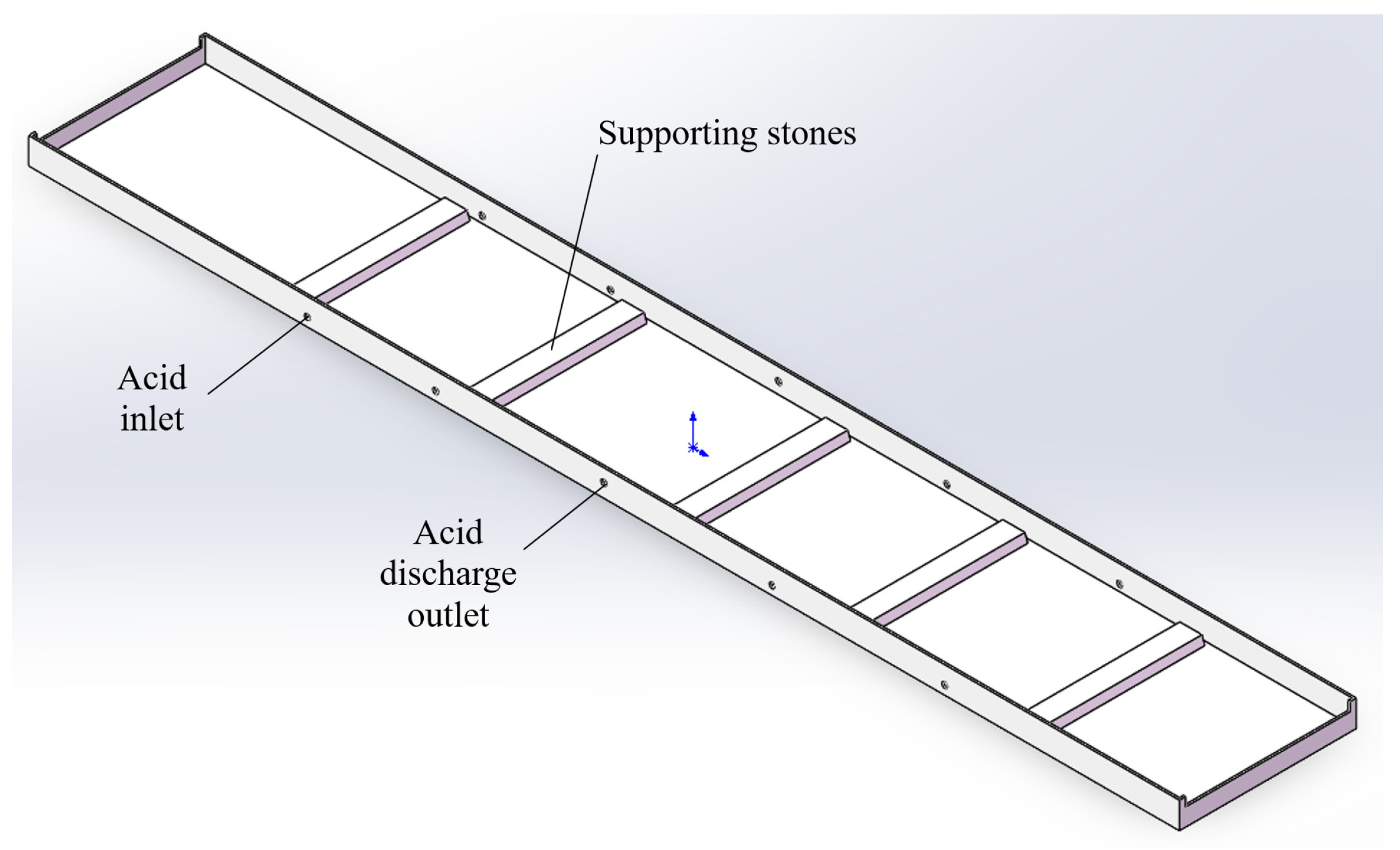
3D model of the tank: The tank dimensions are 13,000 mm × 2000 mm, and it incorporates a 20° angle bracket attached to the bottom, as depicted in Figure 4. This bracket plays a significant role in distributing the flow pattern within the tank, and its convex shape enhances turbulence. On the one hand, the bracket prevents the strip from settling at the bottom of the tank by providing adequate tension.
Moreover, the tank features eight 60 mm diameter fluid inlets on each side. These inlets allow for adjustments in the inlet flow rate, thereby altering the velocity of the incoming fluid. This arrangement promotes increased turbulence near the lower surface of the strip, consequently influencing the turbulent energy of the fluid within the tank. This, in turn, leads to improved pickling quality and reduced pickling time.
For effective reflux, the acid exit is symmetrically positioned at the center of the tank on both sides, facilitating optimal fluid flow and maintaining a balanced distribution within the tank.
3D model of the jet beam: In order to establish a thin temperature and concentration gradient on the steel surface in the turbulent pickling system, a jet is utilized to impact the strip surface. This impinging jet serves two purposes: first, it ensures that the acid enters the holes in the oxide surface quickly, allowing the chemical reaction to proceed; second, it facilitates the oxide’s dissolution and the development of the pickling nucleus. This complex turbulence effect accelerates the replacement speed of iron ions and hydrogen ions, as well as the growth of the fracture between the iron oxide.
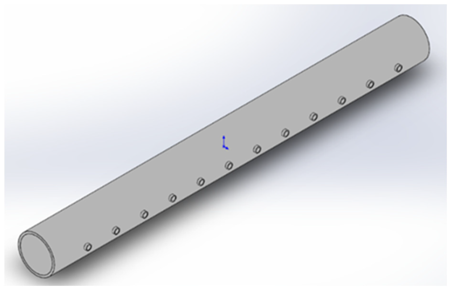
Figure 5 illustrates the acid spray beam at the inlet section, which consists of 12 cylindrical nozzles with configurable spray angles. Figure 6 shows the acid spray beam at the strip’s departure, which is staggered with 25 nozzles, each with a diameter of 20 mm. This arrangement generates a high-turbulence shear flow upon impact with the strip, thereby enhancing the pickling quality of the exported strip.
General assembly structure layout diagram: The strip’s movement through the pickling tank results in faster and more linear travel, leading to the formation of a highly turbulent flow on the strip’s surface. As depicted in Figure 7, the pickling tank comprises a pickling tank body, an acid spray beam located on the top side of the inlet and outlet, three inlet jets on the lower side, and an adjustable reflux exit at the bottom. The blue arrow in the figure represents the acid inlet, while the red arrow represents the acid discharge port.
During the continuous pickling operation, the acid is sprayed into the acid tank at an angle through the acid spray beams at the tank’s outlet and input. The injection port on the lower side ejects acid parallel to the lower surface of the strip, whereas the acid spray beam at the entrance ejects acid to the upper surface of the strip in the direction of the strip’s movement. The acid spray beam at the exit, on the other hand, ejects acid onto the upper surface of the steel plate in the opposite direction of the strip.

2.3. Finite Element Meshing

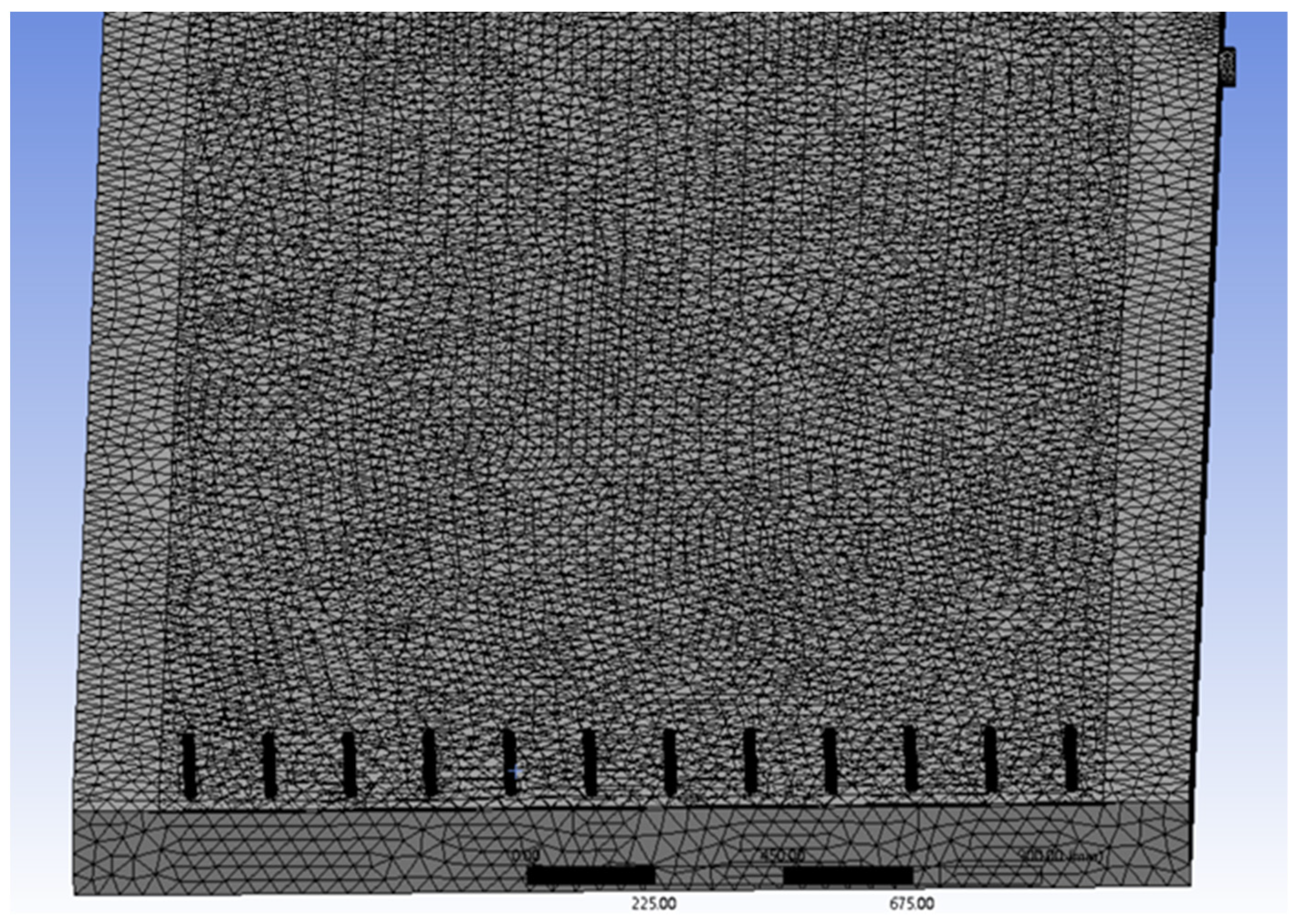
At each end of the turbulent pickling tank, a jet beam propels the pickling solution onto the moving strip surface at a specific jet angle and pressure as the strip enters the tank at a predetermined speed. The discharge apertures located on both sides of the tank’s midsection facilitate the flow of acid back to the acid circulation tank before entering the acid regeneration system. In the DesignModerler software (Ansys 2019, ANSYS, Inc., Canonsburg, PA, USA), the 3D model is categorized into various components, namely the inlet, outlet, wall, and flow-solid coupling surface. The mesh is meticulously divided, as depicted in Figure 8, with further subdivisions at the inlet, outlet, and flow-solid coupling surface, as showcased in Figure 9.

3. Results

By specifying the acid injection speed and strip running speed as variables, respectively, the following turbulence and heat transfer results are obtained using the aforementioned finite element model.

3.1. Flow Field and Heat Transfer Simulation Results at Different Injection Velocities

Utilizing the developed acid bath model described earlier and keeping all other parameters constant, a fluent finite element simulation was carried out by employing the fundamental parameters listed in Table 1. The simulations encompassed various acid incidence velocities, namely 1.2 m/s, 1.4 m/s, 1.6 m/s, and 1.8 m/s.
Simulate the temperature field distribution of acid solution and strip steel at different incident velocities. Figure 10 shows the overall temperature field of the acid solution at an incident velocity of 1.4 m/s, indicating that the temperature of the acid solution at the outlet is higher than that at the inlet. Figure 11 shows the surface temperature field of the strip steel at an incident velocity of 1.4 m/s. Figure 12 shows the temperature field distribution of the longitudinal center section of the pickling tank, with the temperature of the strip steel section shown in the red oval box.
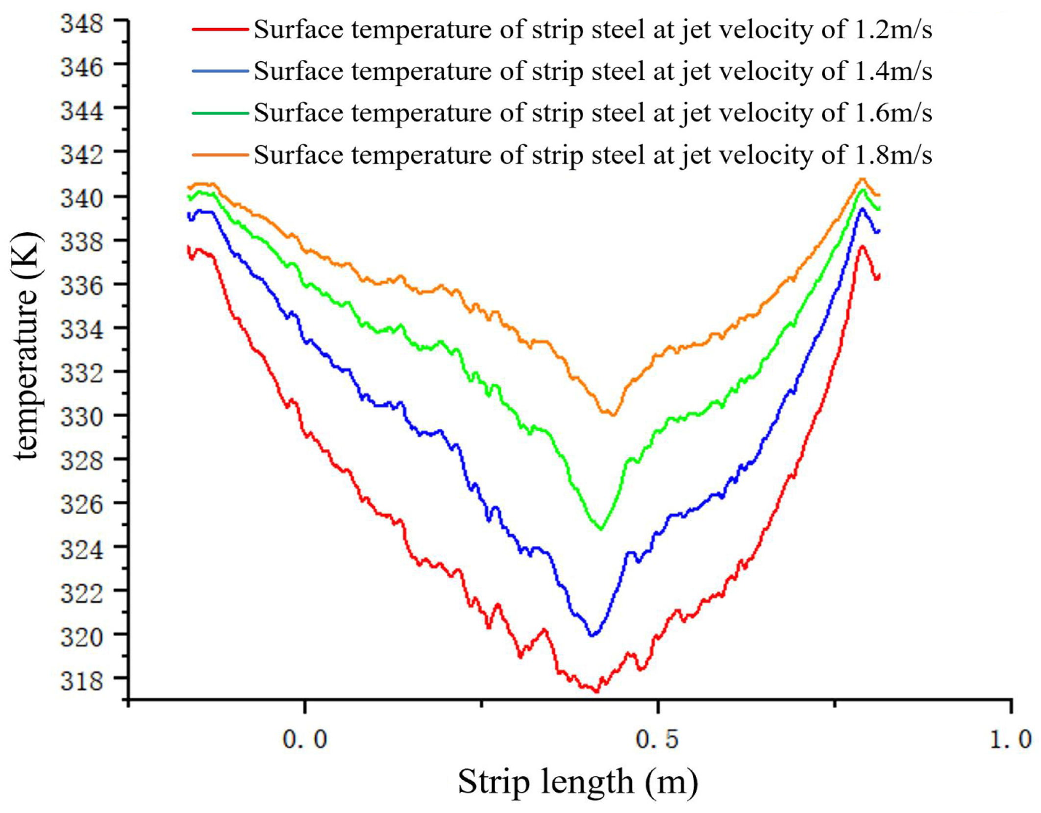
Figure 13 shows the temperature distribution on the longitudinal surface of strip steel in steady state under different incident velocities. It can be seen that the temperature on the surface of strip steel increases with the increase in jet velocity, and the temperature distribution along the longitudinal direction of strip steel is more uniform. The increase in injection speed results in a stronger turbulent effect of the acid solution in the acid tank. Figure 14 shows the calculated distribution of the convective heat transfer coefficient between the surface of the strip steel and the acid solution.
The simulation employs a finite element approach to investigate the impact of incident velocity v and incident acid flow rate Q on the average turbulent intensity I ¯ and average turbulent energy k ¯ in the near-wall region of the strip surface. The boundary conditions remain consistent throughout the analysis.
Table 2 presents the statistical data for turbulence characterization parameters at different incidence flow rates. I ¯ 1 and k ¯ 1 in the table represent the average turbulence intensity and average turbulence kinetic energy in the impact zone, respectively. I ¯ 2 and k ¯ 2 are the average turbulence intensity and average turbulent kinetic energy in the fully developed region, respectively.
In order to obtain data on heat transfer characterization parameters at different incident flow rates, a comprehensive finite element simulation analysis was conducted to investigate the heat transfer between the acid and the strip. This analysis was performed following the modeling of the flow field conditions. The results of this analysis, including the heat transfer characterization quantities, are presented in Table 3 below.
Among them, λ ¯ 1 is the average convective heat transfer coefficient near the wall of the strip inlet area. λ ¯ 2 is the average convective heat transfer coefficient near the wall of the strip exit area; T ¯ 1 is the average temperature near the wall of the strip entrance area; T ¯ 2 is the average temperature near the wall of the strip exit area.

3.2. Flow Field and Heat Transfer Simulation Results at Different Strip Speeds

Subsequently, the simulation was conducted to analyze the variations in the acid flow field and heat transfer within the pickling tank as the strip speed was modified. The obtained data from the Fluent finite element simulation was processed using Origin software (Origin 2021, OriginLab Corporation, Northampton, MA, USA). While keeping the fundamental parameters listed in Table 1 constant, the strip velocity R was adjusted to 60 m/s, 90 m/s, 120 m/s, and 150 m/s.
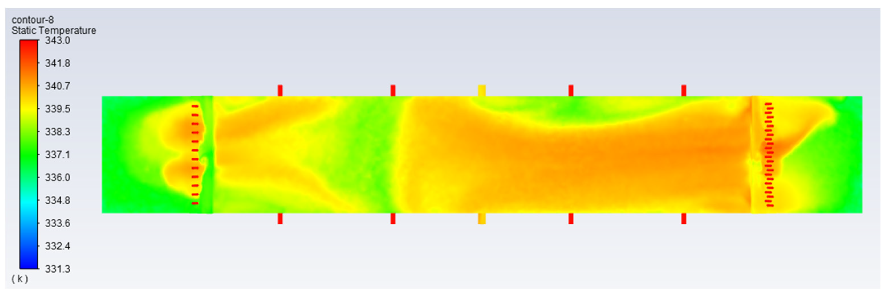
Simulate the temperature fields of the acid solution and strip steel at different strip speeds. Figure 15 shows the overall temperature field of the acid solution at a strip steel speed of 120 m/min. It can be seen that the temperature of the acid solution at the outlet is higher than that at the inlet. Figure 16 shows the surface temperature field of the strip steel at a speed of 120 m/min.
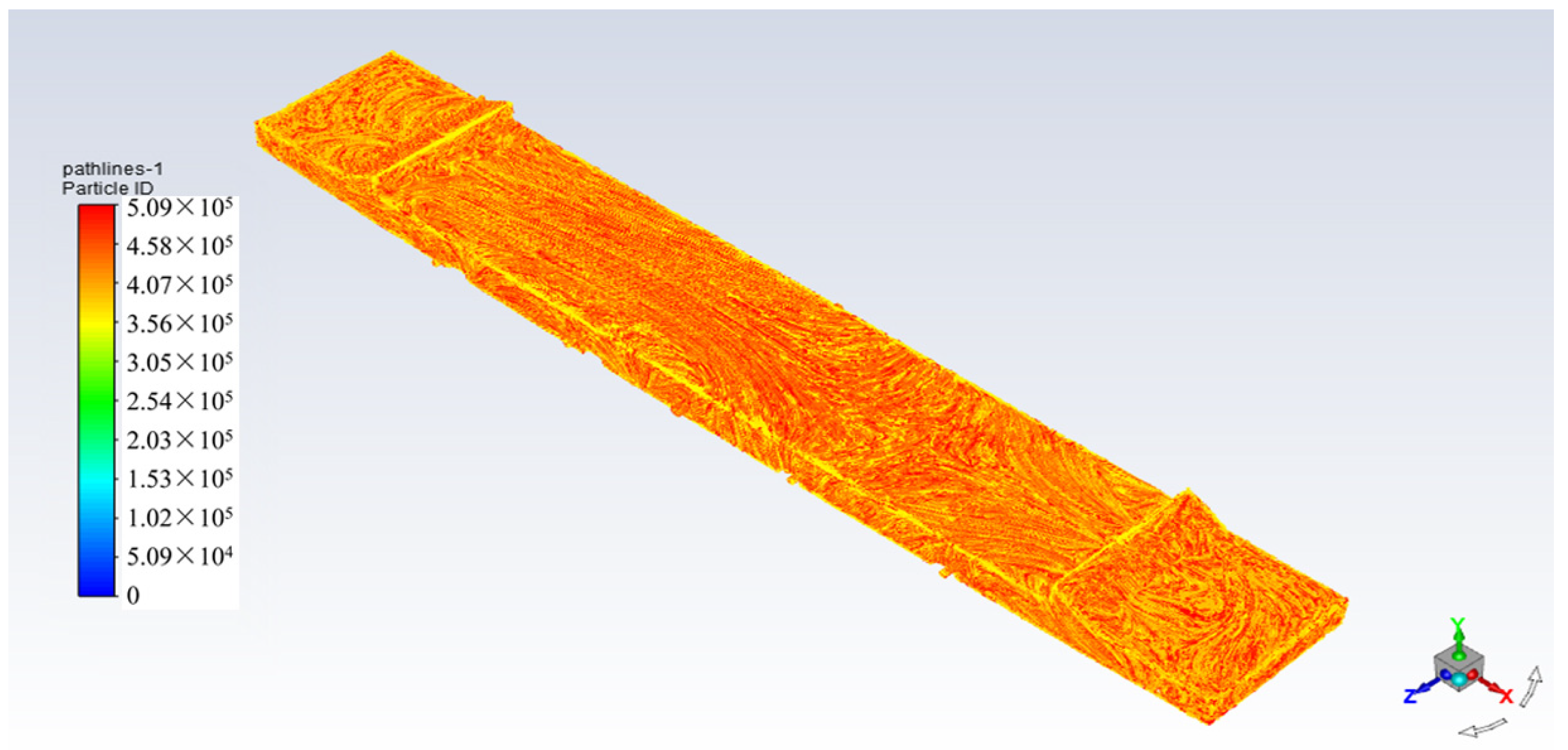
Figure 17 shows the trace of the acid flow field at a strip steel speed of 120 m/min, indicating symmetry in the fluid trace. This is due to the symmetrical distribution of eight acid inlets on the side of the pickling tank.
Figure 18 shows the curve of strip surface temperature at different strip speeds. It can be seen that the strip surface temperature increases with the increase in strip speed, and the temperature distribution is more uniform, which also shows that the increase in strip speed makes the acid in the acid tank have a stronger turbulence effect. Finally, the flow field parameters at different strip speeds were calculated as shown in Table 4.

4. Discussion

From the above simulation results, the following conclusions can be drawn:

4.1. Effect of Injection Velocity on Flow Field and Heat Transfer

The release of the jet from the nozzle at a specific velocity creates an intermittent surface due to a velocity discontinuity. This surface, being inherently unstable, leads to fluctuations and the formation of vortices, thereby causing turbulence in the system.
Based on the calculations presented in Table 2, it is observed that the injection velocity at the injection port accounts for 4.5% of the turbulence intensity. The injection of acid into the tank generates impact momentum and pressure at the stagnation point, which in turn affects a larger surface area of the strip. With an increase in the acid injection flow rate from 41.85 m3/h to 75.32 m3/h, the intensity of surface turbulence in the impact region rises from 19.7% to 34.4%. This 14.7% increase, along with a more significant shift in turbulent kinetic energy, indicates a higher degree of turbulence in the flow field. Additionally, the fully developed region in the middle of the tank experiences an increasing incidence of port-induced turbulence. It is worth noting that the turbulent intensity of the flow is primarily influenced by the flow rates of the injection ports on both sides of the acid tank and the lower side of the strip, rather than the Reynolds number associated with the incidence velocity.
The study reveals that the turbulence intensity at the inlet and outlet sections of the acid tank’s strip surface is significantly influenced by the incident velocity of the acid jet. The jet boundary gradually expands to both sides upon entering the tank, and the impact velocity on the strip surface is also substantial. The stagnation point on the surface experiences high turbulence intensity and has the weakest velocity, heat, and mass transfer boundary layers. Subsequently, the fluid on the strip’s surface undergoes a transition to wall flow, the velocity direction changes, and the turbulence intensity gradually decreases.
The large number of nozzles at the exit leads to a higher volume flow rate per unit time and increased momentum generation when the incident velocity is constant. This results in higher impact kinetic energy, causing a significant rise in both turbulence intensity and temperature. Hence, the strip surface experiences high turbulence intensity and temperature at the exit of the acid tank. Consequently, a considerable amount of turbulence is generated. At a specific incident velocity inside the acid tank, the temperature increase fluctuates slightly, but the turbulence intensity distribution on the upper surface of the strip remains nearly constant. As a result, the incident jet has a more significant impact on turbulence intensity and temperature rise at the strip inlet and outlet than those inside the acid tank at high incident velocities.
Based on the calculations presented in Table 3, it can be observed that the flow rate of the acid injection is higher at the spray beam injection port, where the strip exits more frequently. Due to the strip’s rapid movement in the opposite direction of injection at the exit, a shear flow is created, which facilitates convective heat transfer between the strip and the acid. As a result, the strip’s temperature rises more quickly, with the exit temperature being approximately 8–10 K higher than the inlet temperature. Increasing the inlet speed and flow rate of the acid jet can effectively improve the heat transfer between the strip steel and the acid. This can raise the temperature of the strip steel close to the acid temperature, promoting the chemical reaction of pickling and improving the quality of pickling.
The momentum of the acid reaching the strip’s surface increases considerably with an increase in injection speed and flow rate, leading to a decrease in the temperature boundary layer thickness in the impact area and lowering the temperature gradient on the impact surface, thereby significantly increasing the temperature rise. When the acid flow rate Q is increased from 41.85 m3/h to 75.32 m3/h, the inlet heat transfer temperature improves from 290.75 K to 298.35 K, and the exit heat transfer temperature increases from 298.25 K to 307.55 K. Increasing the injection speed can increase the temperature rise value under the same conditions. However, the injection speed is limited by the inlet pressure. Increasing the inlet flow rate is recommended to ensure higher heat and mass transfer.

4.2. Effect of Strip Movement Speed on Flow Field and Heat Transfer

The acid jet undergoes a transformation into a wall jet upon reaching the surface of the sliding steel plate, inducing a vortex near the wall. The flow field traces illustrate that larger vortices grow as they extend into the fully developed area, eventually breaking down into smaller, more complex vortices as the strip moves.
According to the findings presented in Table 4, as the speed of the strip motion is increased from 30 m/min to 150 m/min at a constant injection speed, the turbulence intensity value on the surface of the strip in the middle of the acid tank (i.e., the fully developed zone) doubles, and the turbulent kinetic energy nearly quadruples. Therefore, the strip’s movement speed significantly impacts the turbulence effect on the strip surface in the midst of the acid bath. When the strip is stationary or moving slowly, the flow boundary at the near-wall layer exiting the stagnation point zone is thicker. As the strip velocity increases, the turbulence intensity steadily increases, the flow boundary layer thickness starts to reduce, and the measured velocity fluctuations at the near-wall surface become more prominent.
The increased motion velocity of the strip induces shear stress on the viscous bottom layer of the fluid in the near-wall region, resulting in a thinner flow boundary layer. The combined effects of the acid jet, strip motion, and acid tank bottom torus generate a pronounced deformation vortex at the inlet and outlet of the acid tank. This vortex intensifies the turbulent intensity and turbulent kinetic energy of the near-wall layer at the stagnation point, thereby enhancing the heat transfer efficiency between the acid and the strip. Moreover, the strip’s velocity in the fully developed region inside the acid tank influences the turbulence characteristics of the near-wall layer. Consequently, higher strip velocities in the turbulent pickling tank can visibly augment the intensity of the turbulent flow on the strip surface.
The movement of the strip introduces a significant shear stress on its surface, leading to notable changes in the distribution of the boundary layer on the steel plate. The strip speed plays a crucial role in determining the characteristics of the boundary layer. Higher strip speeds result in thicker and more uniform boundary layers, along with increased convective heat transfer coefficients. However, when the strip moves towards the exit, the velocity and temperature boundary layers in the impact region thicken with increasing strip speed, which leads to a decrease in the heat transfer rate in that area. Nevertheless, higher strip speeds also correspond to increased convective heat transfer coefficients between the acid and the strip in the near-wall layer. Consequently, increasing the strip speed can enhance the overall heat transfer rate and promote more uniform heating across the surface.
While a high strip movement speed is beneficial for the turbulent pickling process, it is also crucial to provide sufficient time for the strip to move through the pickling tank to ensure the desired pickling quality, i.e., a complete chemical reaction on the strip surface. However, the length of the pickling tank imposes a constraint on the strip movement speed.

5. Application of Research Results

To verify the correctness of the above research results, they were applied to on-site production. Using the 1420 pickling line of a certain steel plant as the experimental platform, on-site experiments were conducted on B510L steel grades that are prone to color difference defects. The basic parameters of the pickling tank are shown in Table 1, and the content of each element and hot rolling parameters are shown in Table 5. The pickling process parameters are shown in Table 6.
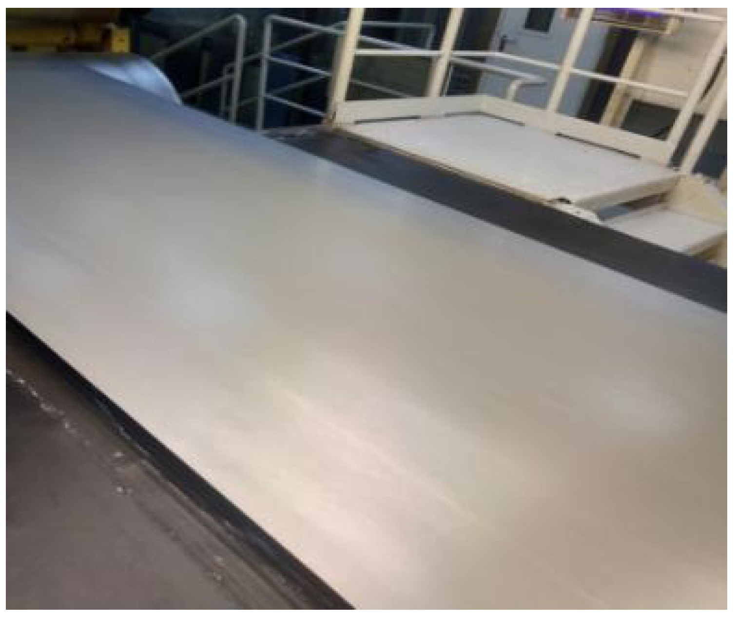
Due to the increase in turbulence, the strip steel can be pickled at a faster speed, increasing the pickling speed from 86 m/min to 115 m/min, greatly improving the pickling efficiency. While improving the pickling efficiency, it is also necessary to ensure the surface quality of the strip steel. The experiment found that the surface quality of the strip steel after pickling is good, as shown in Figure 19.
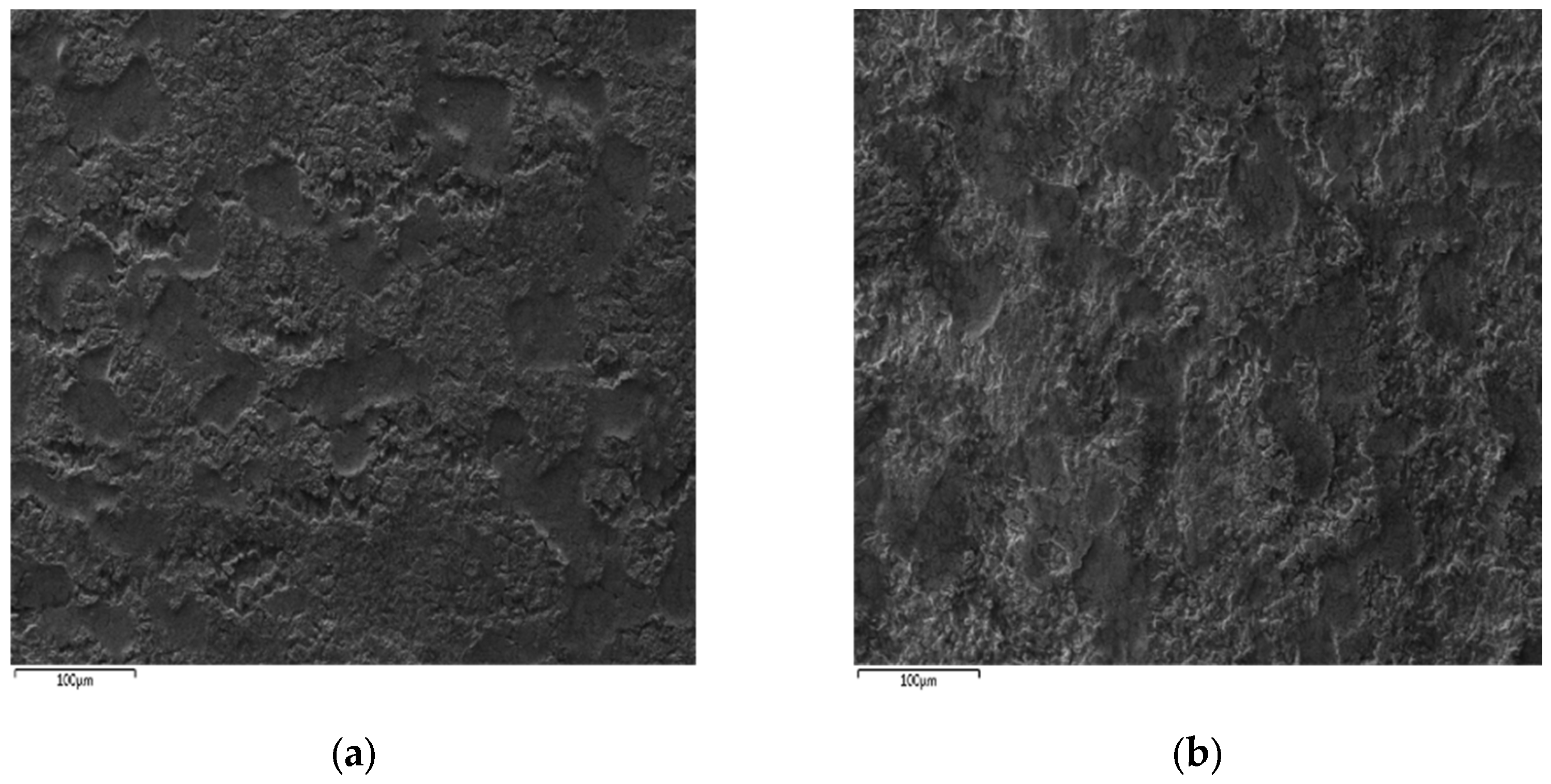
After on-site testing, the surface morphology of strip steel samples with and without color difference defects was observed using scanning electron microscopy, as shown in Figure 20. Figure 20a shows the morphology of the color difference area of the strip steel before the experiment, with a rough and fragmented surface and an obvious oxide layer. Figure 20b shows the morphology of the color-free area of the strip steel after the experiment, with a relatively smooth and flat surface and no obvious oxide layer. This indicates that the surface quality of the strip steel has improved after the experiment.
At the same time, the situation of color difference defects on the surface of the strip steel after applying the research results to the site was statistically analyzed. As shown in Table 7 below, the incidence of severe color difference defects in B510L strip steel for 1 month before and after the test was statistically analyzed. The occurrence rate of severe color difference defects shown in Figure 1 decreased by 13.4%.
From the above data, it can be seen that after increasing the acid spray speed and strip steel speed, the surface quality of the strip steel after pickling still improved. Therefore, this study can improve the production efficiency of the unit while ensuring the quality of pickling. It is of great help to improve the on-site economic benefits.

6. Conclusions

This study focuses on the development of an acid turbulent flow model for strip pickling and utilizes this model to simulate acid turbulent flow under different acid injection and strip movement speeds. The key findings of the study are as follows:
(1)
The turbulence intensity is influenced by the flow rate of the injection ports on the acid tank’s sides and the lower side of the strip. It is not significantly affected by increasing the incidence velocity. However, at high incidence velocities, the jet has a considerable impact on turbulence severity and temperature rise at the strip’s exit and entrance, while its impact inside the acid tank is relatively minor;
(2)
Enhancing the heat exchange between the acid and the strip can be achieved by increasing the incidence speed and the flow rate of the acid jet. This approach encourages the strip’s temperature to rise closer to the acid’s temperature, leading to accelerated chemical pickling reactions and improved pickling quality;
(3)
The velocity of the strip’s movement plays a crucial role in determining the turbulence formed on its surface within the acid bath. By increasing the strip’s motion speed, the rate of surface heat transfer can be enhanced, resulting in more uniform heating.
These findings highlight the importance of optimizing the incidence speed, flow rate of the acid jet, and strip movement velocity to achieve efficient and high-quality strip pickling.

Author Contributions

Conceptualization, X.C.; Data curation, S.A.E.; Formal analysis, J.S.; Methodology, Z.B.; Validation, X.C., J.W. and X.L.; Writing—original draft, X.C.; Writing—review and editing, X.L. and Z.B. All authors have read and agreed to the published version of the manuscript.

Funding

This research was funded by the Science and Technology Research Project of Higher Education Institutions in Hebei Province, the Major Scientific and Technological Achievements Transformation Project of Hebei Province, and the Basic Project of Higher Education Institutions in Liaoning Province, grant number CXY2023012, 22281001Z and LJKZZ20220040.

Data Availability Statement

Not applicable.

Conflicts of Interest

The authors declare no conflict of interest.

References

  1. Li, Y.; Liao, W.; Liu, X. Online measurement system for acid concentration in cold rolling pickling line. J. Wuhan Eng. Vocat. Tech. Coll. 2022, 34, 41–44. [Google Scholar]
  2. Li, H.; Wu, S.; Lu, J.; Yue, C. Oxide Scales on Commercial Hot Rolled 1.5% Si Non-oriented Electrical Steel and the Pickling Behaviors. Metallogr. Microstruct. Anal. 2022, 11, 183–190. [Google Scholar] [CrossRef]
  3. Xingrun, C.; Jing, G.; Kai, H. Immersion pickling of oxide layer on hot-rolled 2205 duplex stainless steel in sulfuric acid with different additives. Metall. Res. Technol. 2022, 119, 210. [Google Scholar]
  4. Li, Y.; Xia, L.; Sun, R.-S. Study on the effect of element enrichment on the surface of high-strength pickling steel on the film-forming performance of phosphating film. J. Phys. Conf. Ser. 2023, 2454, 012020. [Google Scholar] [CrossRef]
  5. Hudson, R.M.; Warning, C.J. Effect of strip velocity on pickling rate of hot-rolled steel in hydrochloric acid. J. Miner. Met. Mater. Soc. 1982, 2, 65–70. [Google Scholar] [CrossRef]
  6. Zhaoning, Z.; Jie, Z.; Ning, K.; Hongbo, L. Strip Pickling Efficiency on the Basis of Combined Parameters Optimization during Tension Leveling Process. J. Mech. Eng. 2019, 55, 51–63. [Google Scholar] [CrossRef]
  7. Yamaguchi, S.; Yoshida, T.; Saito, T. Improvement in Descaling of Hot Strip by Hydrochloric Acid. ISIJ Int. 1994, 34, 670–678. [Google Scholar] [CrossRef]
  8. Peng, J.; Yang, Y.; Li, M. Pickling behavior of 2205 duplex stainless steel hot-rolled strips in mixed solutions of HNO3-HF. Mater. Res. Express 2022, 7, 046502. [Google Scholar] [CrossRef]
  9. Li, N.; Liu, C.; Zhao, Y. Improvement and quality control of turbulent flow pickling process for cold rolled silicon steel shallow grooves. Jiangxi Metall. 2018, 38, 23–26. [Google Scholar]
  10. Grube, N.E.; Martín, M.P. Compressibility effects on Reynolds stress amplification and shock structure in shock-isotropic turbulence interactions. J. Fluid Mech. 2023, 958, A1. [Google Scholar] [CrossRef]
  11. Cheng, C.; Fu, L. A scale-based study of the Reynolds number scaling for the near-wall streamwise turbulence intensity in wall turbulence. Int. J. Heat Fluid Flow 2023, 101, 109136. [Google Scholar] [CrossRef]
  12. Shao, S. A Study on the Mathematical Model of Turbulent Hydrochloric Acid Pickling for Hot Rolled Strip Steel. Master’s Thesis, East China University of Science and Technology, Shanghai, China, 2015; pp. 33–45. [Google Scholar]
  13. Noda, N.; Hendra, H.; Oosato, M.; Suzumoto, K.; Takase, Y.; Li, W.B. Strength Analysis for Shrink Fitting System Used for Ceramics Rolls in the Continuous Pickling Line. Key Eng. Mater. 2011, 462, 1140–1145. [Google Scholar]
  14. O’Donovan, T.S.; Murray, D.B. Fluctuating fluid flow and heat transfer of an obliquely impinging air jet. Int. J. Heat Mass Transf. 2008, 51, 25–26. [Google Scholar] [CrossRef] [Green Version]
  15. Yang, Y.T.; Wang, Y.X. Three-dimensional numerical simulation of an inclined jet with cross-flow. Int. J. Heat Mass Transf. 2005, 48, 19–20. [Google Scholar] [CrossRef]
  16. Pielsticker, K. Modern pickling lines with Vario technology. Metall. Plant Technol. Int. 1995, 18, 4. [Google Scholar]
  17. Dhamodaran, M.; Jegadeesan, S.; Kumar, R.P. Analysis and Calculation of the Fluid Flow and the Temperature Field by Finite Element Modeling. Meas. Sci. Rev. 2018, 18, 59–64. [Google Scholar] [CrossRef] [Green Version]
  18. Alves, M.A.; Oliveira, P.J.; Pinho, F.T. Numerical Methods for Viscoelastic Fluid Flows. Annu. Rev. Fluid Mech. 2021, 53, 509–541. [Google Scholar] [CrossRef]
  19. Ye, T.; Pan, D.Y.; Huang, C.; Liu, M.B. Smoothed particle hydrodynamics (SPH) for complex fluid flows: Recent developments in methodology and applications. Phys. Fluids 2019, 31, 011301. [Google Scholar] [CrossRef]
  20. Shadloo, M.S.; Oger, G.; Le Touze, D. Smoothed particle hydrodynamics method for fluid flows, towards industrial applications: Motivations, current state, and challenges. Comput. Fluids 2016, 136, 11–34. [Google Scholar] [CrossRef]
  21. Asbar; Mubarak, A.Z.; Supanji, M.; Irwansyah; Irwansyah. Stress Analysis of the LN2 Storage Container on Head and Nozzles Using Finite Element Method. In Proceedings of the 2nd International Conference on Experimental and Computational Mechanics in Engineering: ICECME 2020, Banda Aceh, Indonesia, 13–14 October 2020; 2020. [Google Scholar]
  22. Zhao, J.; Wu, G.; Zhang, J. Thermodynamics-CFD-DPM modeling of dross formation and diffusion in a Zn-0.3Al galvanizing bath. J. Mater. Res. Technol. 2023, 23, 3651–3664. [Google Scholar] [CrossRef]
  23. He, F.; Li, M.; Wang, B.J. Multi-mode acid concentration prediction models of cold-rolled strip steel pickling process. J. Process Control 2014, 24, 916–923. [Google Scholar]
  24. Gines, M.J.L.; Benitez, G.J.; Perez, T.; Merli, E.; Firpo, M.A.; Egli, W. Study of the picklability of 1.8 mm hot-rolled steel strip in hydrochloric acid. Lat. Am. Appl. Res. 2002, 32, 281–288. [Google Scholar]
  25. Kalasin, N.N.; Yenchum, S.; Nilsonthi, T. Adhesion behaviour of scales on hot-rolled steel strips produced from continuous casting slabs. Mater. Today-Proc. 2018, 5, 9359–9367. [Google Scholar] [CrossRef]
  26. Peng, J.G.; Li, M.C. Pickling Behaviour of 2205 Duplex Stainless Steel Hot-Rolled Strips in Sulfuric Acid Electrolytes. Adv. Mater. Sci. Eng. 2020, 2020, 4562418. [Google Scholar] [CrossRef] [Green Version]
  27. Liu, X.J.; Cao, G.M.; Nie, D.M.; Liu, Z.Y. Mechanism of Black Strips Generated on Surface of CSP Hot-Rolled Silicon Steel. J. Iron Steel Res. Int. 2013, 20, 54–59. [Google Scholar] [CrossRef]
  28. Khoo, B.C.; Xu, D. A computer analysis of turbulent flow of Acid in the pickling of steel strips. IC-SEC 2002, 1, 171–175. [Google Scholar]
  29. Mehrle, A.; Gittler, P.; Javurek, M.; Osterkorn, A. Numerical, Experimental and Analytical Investigation of the Mass Outflow from a Pickling Tank. In Proceedings of the ASME Pressure Vessels and Piping Conference, San Diego, CA, USA, 25–29 July 2004; American Society of Mechanical Engineers, Pressure Vessels and Piping Division: San Diego, CA, USA, 2004; Volume 46865, pp. 191–199. [Google Scholar]
  30. Wu, D.; Wang, Y.; Liao, Y.; Zhou, Y.; Tian, X.; Xu, L. Study on the pickling behavior and efficient pickling process of hot-rolled SPHC strip steel. Roll. Steel 2022, 39, 44–50. [Google Scholar]
  31. Zou, H.; Yang, Y.; Qin, X. Prediction of Acid Concentration in Continuous Pickling of Strip Steel Based on Deep Learning Optimized by Artificial Bee Colony. In Proceedings of the 34th Chinese Control and Decision Conference, Hefei, China, 15–17 August 2022. [Google Scholar]
  32. Wang, S. Research and Application of Cold Rolling Pickling Model. Shandong Metall. 2022, 44, 45–47. [Google Scholar]
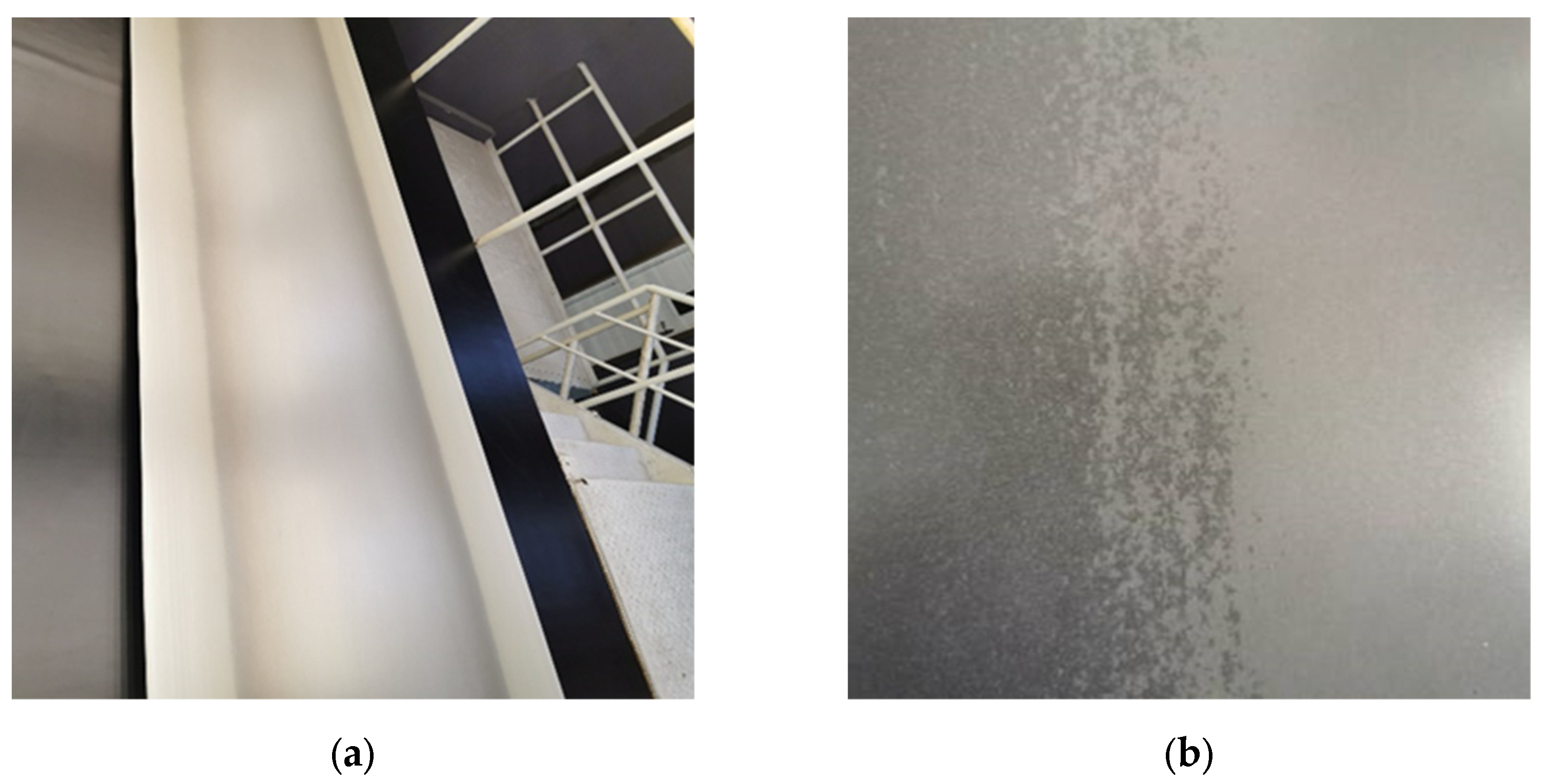
Figure 1. Color difference defects on the surface of strip steel after pickling. (a) Photo of the overall color difference of strip steel; (b) enlarged color difference photo.
Metals 13 01293 g001
Figure 2. A representation of the primary machinery for the section on the pickling process.
Metals 13 01293 g002
Figure 3. Simulation flowchart.
Metals 13 01293 g003
Figure 4. Acid washing tank structure diagram.
Metals 13 01293 g004
Figure 5. Inlet section acid spray beam.
Metals 13 01293 g005
Figure 6. Exit section jet beam.
Metals 13 01293 g006
Figure 7. General assembly diagram of the model.
Metals 13 01293 g007
Figure 8. Grid division diagram.
Metals 13 01293 g008
Figure 9. Partial grid division.
Metals 13 01293 g009
Figure 10. Overall temperature field of acid solution.
Metals 13 01293 g010
Figure 11. Surface temperature field of strip steel.
Metals 13 01293 g011
Figure 12. Temperature field distribution in the longitudinal center section of the pickling tank.
Metals 13 01293 g012
Figure 13. Longitudinal surface temperature distribution of strip steel in steady state at different incident velocities.
Metals 13 01293 g013
Figure 14. Distribution of convective heat transfer coefficient between the strip steel surface and acid solution.
Metals 13 01293 g014
Figure 15. The overall temperature field of acid solution at a strip steel speed of 120 m/min.
Metals 13 01293 g015
Figure 16. Surface temperature field of strip steel at a speed of 120 m/min.
Metals 13 01293 g016
Figure 17. Trace diagram of acid flow field at a strip steel speed of 120 m/min.
Metals 13 01293 g017
Figure 18. Surface temperature curve of strip steel at different strip speeds.
Metals 13 01293 g018
Figure 19. Surface quality of B510L strip steel after the experiment.
Metals 13 01293 g019
Figure 20. Microscopic morphology and characterization of the surface of the strip steel before and after the experiment. (a) Color difference position surface topography map of the strip steel before the experiment; (b) Surface topography map of non-chromatic aberration strip steel after the experiment.
Metals 13 01293 g020
Table 1. Main process parameters for turbulent flow simulation in an acid washing tank.
ParameterValue
Hydrochloric acid density (kg/m3)1087
Specific heat capacity of hydrochloric acid (kg·K)4180
Hydrochloric acid viscosity (kg/m·s)0.001
Hydrochloric acid thermal conductivity (m·K)0.6
Incident angle of acid solution (°)60
Strip initial temperature (K)300.15
Acid temperature (K)348.15
Strip speed (m/min)86
Injection speed on the upper side of the strip (m/s)1.4
Injection speed on the lower side of the strip (m/s)1.4
Table 2. Statistics of turbulence characterization quantities at different incident flow rates.
Parameters1st Group2nd Group3rd Group4th Group
Incident velocity v (m/s)1.21.41.61.8
Acid flow Q (m3/h)50.2258.5866.9575.32
Inlet Reynolds number Re25,00030,00035,00040,000
Surface average turbulence intensity I ¯ 1 (%)22.525.330.133.4
Surface averaged turbulent kinetic energy k ¯ 1 (m2/s2)0.0850.1100.1730.257
Surface average turbulence intensity I ¯ 2 (%)8.48.48.58.7
Surface-averaged turbulent kinetic energy k ¯ 2 (m2/s2)0.0170.0180.0190.018
Table 3. Statistics of heat transfer characterization quantities at different incident flow rates.
Parameters1st Group2nd Group3rd Group4th Group
Incident velocity v (m/s)1.21.41.61.8
Convective heat transfer coefficient λ ¯ 1 (W/m2·K)368443545582
Average temperature of strip surface T ¯ 1 (K)318.95320.55323.45325.35
Convective heat transfer coefficient λ ¯ 2 (W/m2·K)534597684728
Average temperature of strip surface T ¯ 2 (K)327.75330.95332.35334.55
Table 4. Statistical table of flow field parameters at different strip speeds.
Parameters1st Group2nd Group3rd Group4th Group
Strip speed R(m/min)6090120150
Surface average turbulence intensity I ¯ 1 (%)25.730.431.534.6
Surface-averaged turbulent kinetic energy k ¯ 1 (m2/s2)0.1060.1350.1520.175
Surface average turbulence intensity I ¯ 2 (%)8.49.611.514.6
Surface-averaged turbulent kinetic energy k ¯ 2 (m2/s2)0.0130.0160.0200.028
Convection heat transfer coefficient λ ¯ 1 (W/m2·K)4.384.404.484.49
Average strip surface temperature T ¯ 1 (℃)48.549.350.150.5
Convection heat transfer coefficient λ ¯ 2 (W/m2·K)5.495.645.705.74
Average strip surface temperature T ¯ 2 (℃)57.458.961.563.3
Table 5. Content of various elements in B510L strip steel.
ParametersC ContentSi ContentMn ContentCoiling Temperature
Parameters value0.005 %0.4%1.85%500 °C
Table 6. Acid cleaning process parameters used in the experiment.
ParametersAcid Injection Speed of Above Side (m/s)Acid Injection Speed of Below Side (m/s)Strip Speed (m/min)
Parameters value1.61.6115
Table 7. Statistics on the incidence of severe color difference defects in B510L strip steel before and after the experiment.
ParametersBefore the
Experiment
After the
Experiment
Reduction Value of Color Difference Defect Occurrence Rate
Color difference defect occurrence rate (%)15.72.313.4
Disclaimer/Publisher’s Note: The statements, opinions and data contained in all publications are solely those of the individual author(s) and contributor(s) and not of MDPI and/or the editor(s). MDPI and/or the editor(s) disclaim responsibility for any injury to people or property resulting from any ideas, methods, instructions or products referred to in the content.