Article

Influence of Melt Infiltration Parameters on Structural and Mechanical Properties of Al-4.3wt.%Cu-EP Syntactic Foam

by
Behzad Niroumand
* and
Amir Jazini Dorcheh
Department of Materials Engineering, Isfahan University of Technology, Isfahan 8415683111, Iran
*
Author to whom correspondence should be addressed.
Metals 2023, 13(8), 1345; https://doi.org/10.3390/met13081345
Submission received: 17 June 2023 / Revised: 21 July 2023 / Accepted: 24 July 2023 / Published: 27 July 2023
(This article belongs to the Special Issue Advanced Metallic Foams)

Abstract

:
The present research concerns fabrication of Al-4.3wt.%Cu metal syntactic foams using expanded perlite particles (EPPs). A gas pressure infiltration technique was employed to fabricate the aluminium syntactic foams under different infiltration temperatures and pressures. Ambient air pressure and 750 °C were identified as the favoured processing conditions for full infiltration of the melt. The average density and EP volume percentage of the fabricated foams were measured to be about 1.55 g/cm3 and 50.3%, respectively. Melt infiltration is believed to be mainly controlled by the breakage of the aluminium oxide layer on the melt surface and melt viscosity. Preferential infiltration of the melt between the mould wall and the EP particles bed complemented by radial melt infiltration toward the centre of the samples was identified. The effects of EP particles on growth of the nucleated primary α-aluminium phase were discussed. XRD and EDS analyses suggested some chemical reactions at the interface of EPPs with the molten aluminium. T6 heat treatment in the ambient atmosphere improved the average compressive tensile strength, plateau stress, and absorption capacity of the syntactic foams by more than 100%. Uniform deformation and similar densification strains (about 40%) of the as-fabricated and heat-treated syntactic foams during the compression test suggested uniform distribution of EP particles and metallic struts in the aluminium alloy matrix.

1. Introduction

Metal syntactic foams are a group of advanced metallic foams which mostly use either hollow or porous filler particles within a metallic matrix [1,2,3]. Different types of filler particles including ceramic hollow particles [4,5], metallic hollow particles [6], ceramic porous particles like light expanded clay aggregate (LECA) [7] and pumice [8], fly ash [9], expanded glass [10], and expanded perlite (EP) [11,12,13], as well as hybrid placeholder particles [14], in situ fillers [15], and gradient filler particles [7,16] have been used to fabricate metal syntactic foams.
Metal syntactic foams are strong candidates where thermal, mechanical, dielectric, electromagnetic, sound acoustic, vibration, and insulation properties are required. They are also considered as excellent energy absorber materials in automotive and building industries due to their low-density and porous structure [17,18].
Different types of casting techniques like stir casting and infiltration casting have been employed to manufacture metal syntactic foams [1,17,19,20]. Gravity infiltration casting techniques have been employed to manufacture high melting point alloy matrixes, like steel syntactic foams [21]. Gas pressure [7], low pressure infiltration [22], and counter-gravity infiltration [23] techniques have also been employed to manufacture lower melting point alloy matrixes, like Al, Zn and Mg based alloys syntactic foams. The melt squeezing process as described in [24] could also be used for fabrication of metal syntactic foams as long as the applied pressure does not exceed the threshold pressure for damaging the filler particles.
The influence of the size, shape, volume percentage and type of filler particles, arrangement of different filler particles, and heat treatment of matrix alloys has been investigated experimentally and numerically [1,24,25,26,27,28]. In addition, metal syntactic foam-filled tubes, tube-filled metal syntactic foams, and sandwich panels with metal syntactic foam cores have been manufactured and analysed in recent years [29,30,31,32].
The current research employs a gas pressure infiltration process to fabricate Al-4.3wt.%Cu alloy syntactic foams using expanded perlite particles (EPPs) under different infiltration temperatures and pressures. Then, the suitable processing conditions are selected, and the structure and mechanical properties of the fabricated metal syntactic foams are investigated.
EP was selected as the filler material due to its low-density, low-cost, and stability at the infiltration processing conditions [11,13,25]. Al-4.3wt.%Cu alloy was chosen as the matrix alloy due to its good mechanical properties which can be enhanced by heat treatment. Al-Cu alloys are considered as the strongest cast aluminum alloys. The most favoured copper content in these alloys is around 4.5 wt.% [33]. The strength of Al-Cu alloys relies on solid solution strengthening, precipitation hardening by θ′ and θ″ precipitates, and dispersion hardening by Al2Cu intermetallics [34]. They have been widely used in the transportation and aerospace industries to satisfy the demand for lightweight, high-performance, and easily processable materials. Typical applications include the production of pistons for internal combustion engines, air-cooled cylinder heads for aircraft engines, propellant tank of large launch vehicles, structure components of armored vehicles, and wing and fuselage structures of airplanes [33,35,36].
The scarcity of the published work on the fabrication and characterization of Al-4.3wt.%Cu-EP syntactic foams fabricated through liquid routes was another incentive for selecting this metal foam system.

2. Materials and Methods

2.1. Raw Materials

An Al-Cu alloy and expanded perlite particles (EPPs) were used for synthesis of Al-4.3wt.%Cu syntactic foams. First, premeasured amounts of a commercially pure aluminium ingot (UNS A01001) and electrical copper wires (ASTM C11040) were melted in a gas furnace under Coveral 11S flux (Fars Rizan Mavad Co., Isfahan, Iran). The molten alloy was then degassed using C2Cl6 tablets (Fars Rizan Mavad Co., Isfahan, Iran) and poured in sand moulds with cylindrical cavities to produce 25 mm diameter rods. The chemical composition of the cast rods determined using the Spark Emission Spectroscopy (SES) technique is shown in Table 1.
Liquidus temperature of the alloy was measured to be about 640 °C. To this end, about 400 g of the alloy was melted in a ceramic crucible placed inside a muffle furnace, and its temperature-time variations during cooling was recorded a few times using calibrated K-type thermocouples and a data acquisition system. A typical cooling curve is shown in Figure 1. The density of the cast alloy was measured as 2.8 g/cm3 using the Archimedes’ method.
In order to separate the EPPs (Isfahan Naghshe-Jahan Perlite Co., Isfahan, Iran) from the solid ones, perlite particles were immersed in water for an hour. The floated EPPs were then collected, dried at 200 °C, and sieved. EPPs within the size range of 2.0–2.3 mm were used in the fabrication of Al-4.3wt.%Cu-EP syntactic foams. Scanning electron microscopy (SEM) images of EPPs, as shown in Figure 2, reveal the highly porous structure of the particles. The density of EPPs was measured as 0.33 g/cm3 according to Equation (1) [37], where ρp and ρAl are density of EP particles and aluminum alloy, respectively, Vsf is the syntactic foam volume, and Mp and Msf are EP particles mass and syntactic foam mass, respectively.
ρ p = M p V sf ( M sf M p ρ Al )

2.2. Fabrication Method

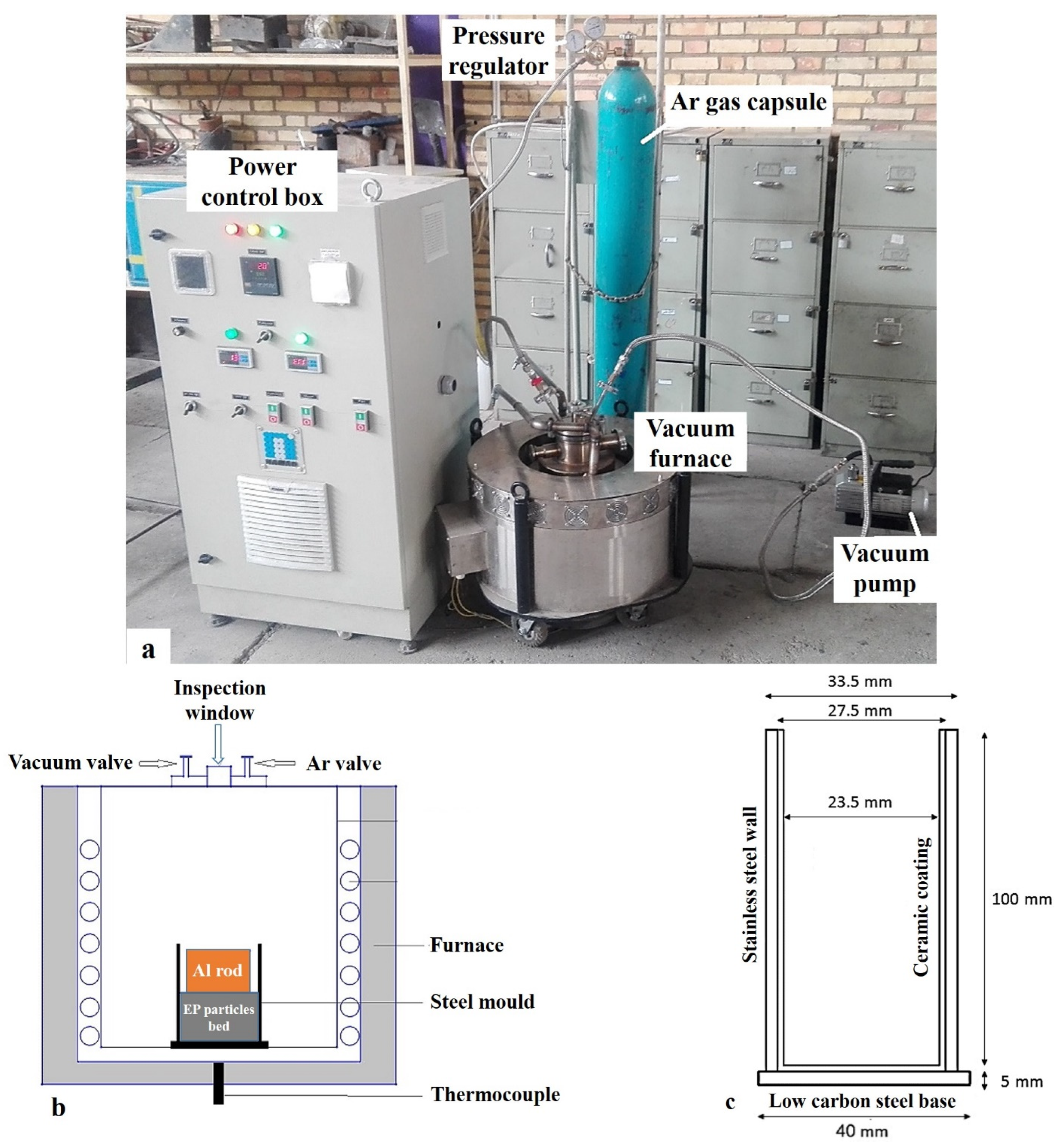
Al-4.3wt.%Cu-EP syntactic foams were fabricated in a vacuum melting/pressure infiltration set-up (Figure 3). The set-up consisted of a resistance furnace encapsulated in a stainless steel vacuum/pressure chamber and fitted with vacuum and gas inlet/outlets.
The dimensions of the refractory-lined cylindrical steel moulds specifically made for infiltration of the syntactic foam samples in this work are shown in Figure 3c. An alumina refractory slurry containing about 5 wt% CaO was used for lining the moulds. The ceramic lining prevents any likely reactions between the aluminium alloy and the steel mould during the melting and infiltration process and facilitates removal of the fabricated syntactic foam from the mould. The diameter of the cylindrical cavity available for EPPs filling in each mould was about 23.5 mm.
The lined steel mould was then filled with a carefully weighted amount of EPPs and was vibrated for a few seconds to ensure uniform compaction of EPPs. Subsequently, a machined Al-4.3wt.%Cu rod (length and diameter of 40 and 20 mm, respectively) was placed on top of the EPPs inside the mould (Figure 3b). The bottom surfaces of the rods were concentrically grooved to facilitate the rapture of the oxide layer formed on its surface during infiltration [38]. In each experiment, four such assemblies were placed in the vacuum melting set-up and heated under 0.04 bar vacuum. The infiltration experiments were performed at 700, 725, and 750 °C at three different pressures of 0.8, 1.5, and 2.0 bars, as demonstrated in Table 2.
The infiltration temperatures were selected based on some preliminary experiments to ensure adequate fluidity of the melt during the infiltration process. Infiltration pressures of 1.5 and 2.0 bars were provided by the application of Ar gas. The lowest infiltration pressure of about 0.8 bar was provided by simply opening the vacuum valve and letting the atmosphere pressure in the chamber, which is about 635 mm Hg (0.84 bar) at Isfahan, Iran.
In each experiment, after stabilization of the target temperature, the vacuum valve was shut off and the gas pressure valve was switched on. Introduction of the argon gas/air within the furnace would result in infiltration of the molten Al alloy between the open passages of the EPPs bed. The pressure valve was switched off after 1 min, and the mould was quickly removed from the set-up and bottom cooled in a 7 mm deep water bath.
Some selected samples were T6 heat-treated. T6 is a two-step precipitation hardening treatment, including solution treating at a high temperature followed by artificial ageing at a lower temperature. To this end, the samples were soaked at 525 ± 5 °C for 15 h in either air or vacuum (foams were encapsulated in quartz tubes) atmospheres and quenched in water at room temperate. They were then artificially aged at 160 ± 5 °C for 8 h [39,40].

2.3. Characterization

The cooled samples were removed from the moulds and visually inspected to ensure the extent and mode of infiltration of the melt in the EPPs bed. The density of the fabricated metal syntactic foams was measured according to [37]. Fully infiltrated samples were then sectioned, and the microstructure of the fabricated metal syntactic foams were characterized using an optical microscope (Nikon-EPISHOT300, Melville, NY, USA) and an SEM (Philips-XI30, Eindhoven, Netherland) equipped with an EDAX energy-dispersive X-ray spectroscopy (EDS) analyser with accelerating voltage of 20 kV. Average dendrite cell size was measured using the liner intercept method [41] and ImageJ software. Phase analyses of the EPPs and the reaction products between the EPPs, and the aluminium alloy matrix were performed using the X-ray diffraction method (XRD, Asenware AW-DX300, Manchester, England, Cu , scan speed = 3°/min, 40 kV, 30 mA, λ = 0.154056 nm, and 2θ = 10–90) and X’Pert HighScore software v.3 (Malvern Panalytical, Malvern, UK). Viscosity-temperature dependence of the molten alloy was estimated using the built-in viscosity module and data bank of ProCAST simulation software v.2016.01 (ESI Group, Rungis, France) for Al-4.5wt.%Cu composition and assuming melt as a Newtonian fluid.
Uniaxial compression tests (Wolpert- FM2750, Bretzfeld, Germany) on the successfully fabricated Al-4.3wt.%Cu syntactic foams were carried out according to ISO-13314 standard [42] on machined cylindrical specimens of height and diameters of 22 and 20 mm, respectively. Each test was repeated three times.
The relative dispersion of the experimental results for density of EP, EP volume percentage, SDAS, and mechanical properties has been shown by ±values of the average measurements. The reported value after each ± sign represents “error of the mean” of the measurement.

3. Results and Discussion

3.1. Infiltration of the EPPs Bed

The processing parameters controlling the infiltration of a porous bed with a liquid have been described by a number of equations, including those of Darcy, Blake-Kozeny-Carman, Kaptay, and Ergun [43,44,45,46]. According to Ergun’s equation, which considers viscous, inertial, and capillary terms in the flow of liquid through a porous media, the minimum pressure difference between the molten aluminium alloy and the porous EPPs bed depends on the porous bed characteristics (length, porosity, and tortuosity of the bed, as well as the average particle diameter) and the liquid properties (density, viscosity, and superficial velocity through the bed). From the processing point of view, the main manufacturing parameters that control the infiltration process include infiltration temperature, pressure, and time. The infiltration pressure must be higher than a threshold pressure, which can be estimated by the mentioned equations. Orbulov et al. [46] found that for short infiltration times, the infiltration length is proportional to the product of the applied pressure and the square root of time.
The influence of infiltration temperature on the viscosity of molten Al-4.3wt.%Cu, as extracted from the ProCAST software, is shown in Figure 4. It is obvious that the melt viscosity reduces by increasing the infiltration temperature. For instance, the viscosity of the molten alloy at 750 °C is about 10% less than that at 700 °C. This would result in improved fluidity of the melt and less demanding infiltration in the porous medium.
Temperatures higher than 750 °C would result in even lower viscosities. However, two disadvantageous phenomena may take place at higher temperatures, i.e., greater oxidation rate of the melt before infiltration and higher volume shrinkage of the melt during solidification.
Obviously, melting is not performed under a perfect vacuum in this work. Therefore, oxidation of the ingot surface progresses during heating and melting of the aluminium alloy rods. In fact, the molten metal is encapsulated in a thin alumina oxide layer before the infiltration begins. This oxide layer is clearly seen on the surface of the infiltrated samples, as will be shown later.
Before the onset of the infiltration, the applied pressure needs to break up this oxide layer so the molten metal may be extruded out and find its way between the cavities of the EPPs bed. It is known that higher temperatures result in thicker and more difficult to overcome oxide layers [47].
On the other hand, higher infiltration temperatures result in larger volume shrinkage of the melt and potentially more shrinkage porosity in the metal struts of the solidified foams. For these reasons, higher infiltration temperatures were not employed in this study.
In the following, the influences of the temperature and pressure on successful infiltration of Al-4.3wt.%Cu-EP syntactic foams are discussed.
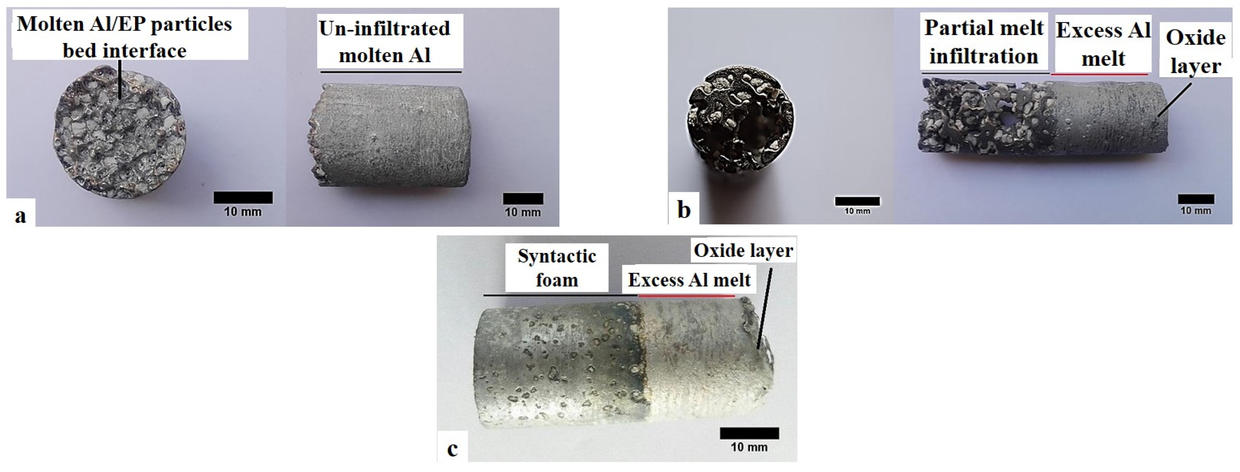
The effects of infiltration temperature on the extent of infiltration of molten Al-4.3wt.%Cu alloy in the EPPs bed at infiltration pressure of 0.8 bar (atmospheric pressure) are shown in Figure 5. It is clear from Figure 5a that at an infiltration temperature of 700 °C (sample F0.8-700), hardly any infiltration of the melt has taken place. The absence of any EPP in the sample is due to the disintegration of the EPPs bed after removal of the sample from the mould. In fact, the aluminium alloy bar melted, but remained unchanged on top of the EPPs bed. In other words, due to the low fluidity of the melt and the small infiltration pressure applied, the melt has not been able to overcome the resistance of the aluminium oxide layer and rapture it. The bottom view of the solidified sample, at the interface of melt/EPPs bed, indicates some deformation of the melt interface to capture a few EPPs (Figure 5a). This is most likely due to local deformation of the flexible ultra-thin oxide layer on the bottom surface of the molten aluminium alloy [47].
With increasing the infiltration temperature to 725 °C (sample F0.8-725), partial infiltration of the EP bed is seen, but the lack of infiltration, especially in the central section of the EPPs bed, is still visible (Figure 5b). The fabricated sample is composed of two different sections, i.e., a partially infiltrated metal syntactic foam and the excess melt on top of the foam (Figure 5b). The oxide layer encapsulating the excess melt is also visible.
It appears that this partial infiltration has taken place by preferential penetration of the melt between the mould wall and the EPPs bed, as schematically shown in Figure 6. The coefficient of thermal expansion (CTE) of the steel mould is a few times larger than that of the EPPs [48]. Therefore, it is believed that an increased temperature would allow for the formation of a larger micro-sized gap between the two. The passages opened by this gap is not as tortuous as those between the EPPs, rendering smaller infiltration pressure threshold requirements.
On the other hand, breakage of the aluminium oxide layer on the melt surface is more likely at higher temperatures due to the difference between the CTE of the aluminium melt and the alumina oxide layer. The CTE of the aluminium melt and the alumina oxide layer are about 70 × 10−6 K−1 [48,49] and 10 × 10−6 K−1 [50], respectively. As a result, the aluminium melt expands a few times more than the oxide layer as the infiltration temperature is increased. This would exert a tensile stress on the oxide layer, leading to its easier rupture. Accompanied with the lower viscosity of the melt and the larger gap between the mould wall and the EPPs bed, it is believed these would result in preferential infiltration of the melt between the mould wall and the EPPs bed (Figure 6). Figure 5b shows limited radial infiltration toward the centre of the sample. However, a large cavity still remains in the middle of the sample and it is evidently far from full infiltration.
Figure 5c suggests that a full infiltration has been achieved by increasing the infiltration temperature to 750 °C (sample F0.8-750). The fabricated sample is composed of two different sections, i.e., an Al-4.3wt.%Cu-EP syntactic foam and the excess melt on top of the foam. Obviously, the increased infiltration temperature reinforces the three-pronged effects explained above. It is believed that at these infiltration conditions, preferential infiltration of the melt between the mould wall and the EPPs bed has been complemented by full radial melt infiltration toward the centre of the sample. The full radial melt infiltration is mainly affected by the lower melt viscosity at this temperature.
The effects of infiltration temperature on the extent of infiltration of molten Al-4.3wt.%Cu alloy in the EPPs bed at infiltration pressures of 1.5 and 2.0 bars are shown in Figure 7. Since no infiltration takes palce in samples F1.5-700 and F2.0-700, their corresponding macrogaphs are similar to that shown in Figure 5a and, therefore, have not been shown.
Incomplete infiltration at 725 °C at both infiltration pressures, and evidence of preferential infiltration of the melt between the mould wall and the EPPs bed are noticeable in Figure 7a,c. Furthermore, it is clear that the extent of infiltration has increased at higher infiltration pressures, as predicted by the Ergun model.
Complete infiltration was achieved at an infiltration temperature of 750 °C at infiltration pressures of 1.5 and 2 bars (Figure 7b,d). The fabricated samples are composed of two different sections, i.e., an Al-4.3wt.%Cu-EP syntactic foam and the excess melt on top of the foam.
It is evident that within the limits of the processing conditions employed in this study, the infiltration temperature had a more pronounced effect than the infiltration pressure. Increasing the infiltration pressure from 0.8 to 2 bars did not change the extent and mode of infiltration significantly, but infiltration was considerably improved by increasing the infiltration temperature at any given pressure. The effect can be discussed in terms of alumina oxide layer rapture, preferential infiltration of the melt between the mould wall, and the EPPs bed and the radial melt infiltration toward the centre of the sample.
Considering the discussed results, and ease of fabrication and non-requirement of pressurized gas cylinders and attachments, infiltration conditions of sample F0.8-750, i.e., infiltration temperature of 750 °C and atmospheric infiltration pressure were selected as the optimum conditions for the fabrication of Al-4.3wt.%Cu-EP syntactic foams. The average density and EP volume percentage of sample F0.8-750 were measured to be about 1.55 ± 0.03 g/cm3 and 50.3 ± 0.8%, respectively.
In another study, Taherishargh et al. [25] fabricated A356-EPP syntactic foams using 2.0–2.8 mm EPPs and mechanical force for infiltration. They reported syntactic foam density of 1.08 g/cm, which is lower than that achieved in this study. This is partly due to lower densities of the matrix alloy (2.67 g/cm2) and the EPPs (0.18 g/cm3) used in their study, as compared with 2.8 g/cm2 and 0.33 g/cm2, respectively, in this study. Furthermore, the EPPs percentage in the fabricated foam was reported to be 64%, which is greater than that in the current study (50.3%).

3.2. Microstructural Studies of the Optimum Sample

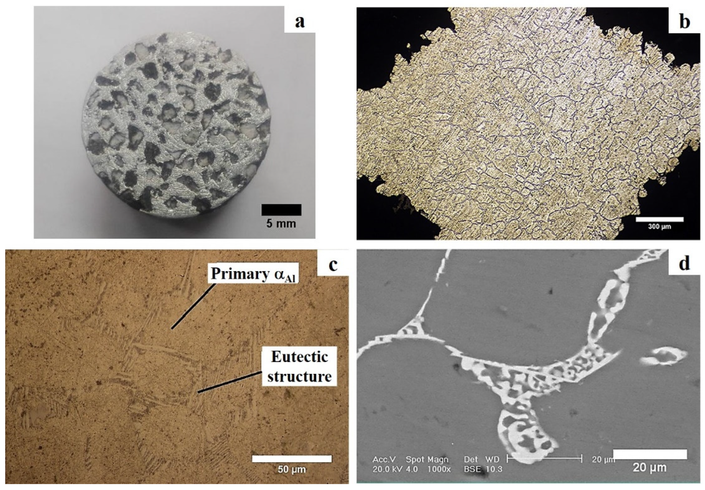
Macro and microstructures of the sample F0.8-750 were investigated by OM and SEM. A typical structure is shown in Figure 8. A macrograph of a cross section of the sample is shown in Figure 8a, where uniform distribution of EPPs in the matrix as well as some dark phases at their interfaces are visible. The microstructure of a strut junction between four EPPs is shown in Figure 8b,c which consists of light colour primary aluminium α phases and a darker eutectic structure at the boundaries of the primary phase. The eutectic structure (Figure 8d) consists mainly of a eutectic aluminium α phase and un-equilibrium Al2Cu precipitates.
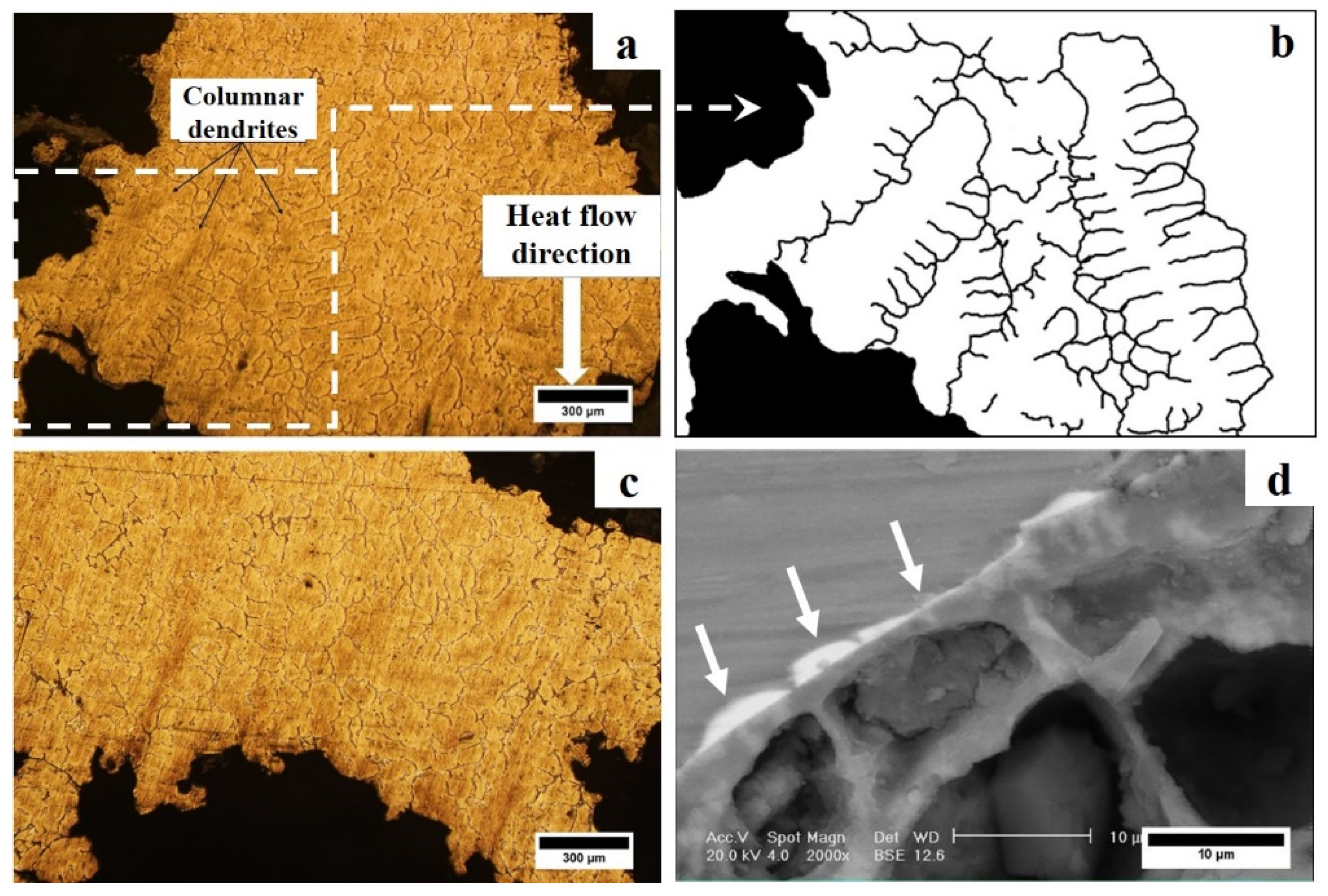
Microstructures of different parts of the metallic struts of F0.8-750 syntactic foam are shown in Figure 9. As pointed out in Section 2.2, all the infiltrated samples were directionally cooled in water. The finer microstructure and smaller dendrite cell spacing at the bottom of the sample compared to those of the top part of the sample are evident in Figure 9a,b. The average dendrite cell spacing for the bottom and upper part of the sample were measured to be about 41 ± 2 and 64 ± 1 μm, respectively.
Using the relationships proposed by Ferreira et al. [51] between the cooling rate and local solidification time with the secondary dendrite arm spacing of Al-4.3wt.%Cu alloy, the local solidification time and cooling rate of the molten metal at the bottom of the mould were approximated to be about 40 s and 2.4 K/s. These parameters were 156 s and 0.62 K/s for the upper part of the mould.
Despite the directional cooling of the sample, evidence of extensive directional solidification was not observed in the microstructure. The heat flow direction as well as some columnar dendrites grown opposite to the heat flow are displayed in Figure 9a. Schematics of some of these dendrites are shown in Figure 9b. No such dendrites could be observed in the upper parts of the sample (such as in Figure 9c). It is believed that the directional growth of the dendrites nucleated at the bottom of the mould is hindered by EPPs due to the mechanical and thermal effects of EPPs’ presence. Firstly, the dimension of the EPPs is many times larger than the grain size of the struts. As a result, EPPs can mechanically stop the directional growth of the grains. Secondly, the thermal properties of the EPPs and the aluminium matrix alloy are very different. The thermal conductivity of EP (0.12 W/m·K) is much lower than that of the matrix alloy (85 W/m·K) [52]. Furthermore, the specific thermal capacity of the former is 1000 J/kg·K, and that of the latter is 850 J/kg·K [53]. These differences result in slower cooling of the melt close to the EPPs. Interference of the thermal fields around each EPP with the thermal gradients imposed by the directional cooling is believed to prevent extensive growth of the columnar dendrites opposite to the cooling direction. In fact, the formation of a considerable number of eutectic phases on the EPP/aluminium matrix interface (marked by white arrows in Figure 9d) suggests that grains were nucleated in the bulk of the infiltrated molten alloy and grew towards the EPPs. Since the solute distribution coefficient of the Al-Cu system (k0) is less than unity [54], copper atoms are rejected from the solidification front and are concentrated in the last part of the structure which is solidified. A directional solidification from the centre of the struts towards the EPPs can be concluded from Figure 9d. Such a growth mode would naturally result is equiaxed rather than columnar grains.
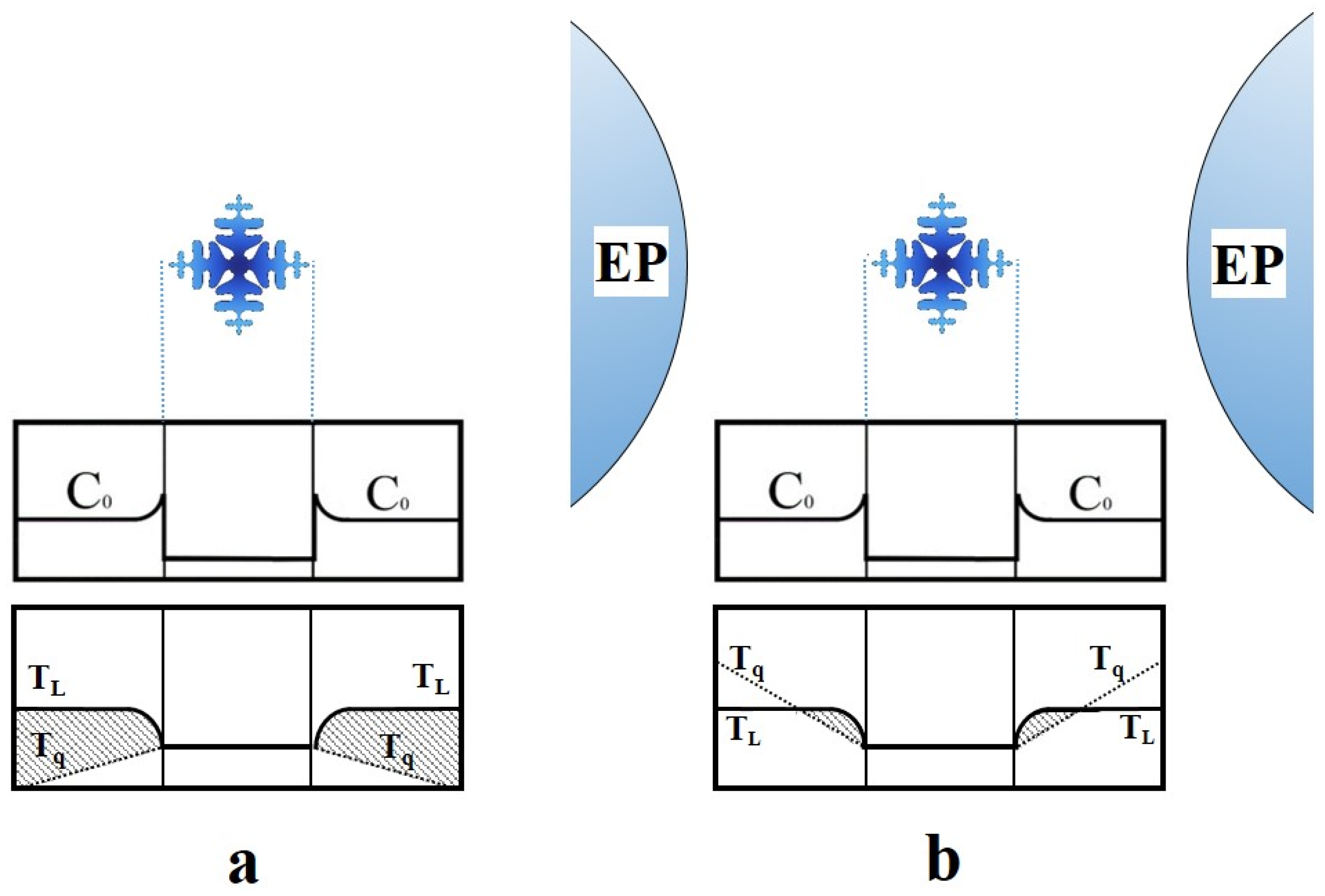
One may notice that despite the water cooling of the fabricated syntactic foam, the equiaxed grains formed in the sample are not as highly branched and complex as those expected in monolithic solid castings. Figure 10 suggests the equiaxed growth conditions in a molten metal infiltrated syntactic foam in comparison with those for a solid casting. In a solid casting, the large undercooled region in front of particles growing in the bulk of the molten metal away from the mould wall consists of a thermal and a solutal component. The thermal component is due to the negative temperature gradient in front of the solid-liquid interface (Tq). The solutal component is the result of the local variation in the liquidus temperature of the melt (Tl) due to solute rejection in front of the solid-liquid interface and the resulting constitutional undercooling (Figure 10a). The resulting total undercooling is large, and the formation of new dendrite arms will persist until late in solidification when the thermal and solutal fields of the neighboring grains overlap.
It is believed that in the solidification of metal syntactic foams, the growth of the equiaxed dendrites sets off similarly. However, very soon the thermal influence of the EPPs will induce a positive thermal gradient and remove the thermal share of the undercooling in front of the growing particles (Figure 10b). As a result, only the constitutional part of the undercooling remains for inducing instability in the solid-liquid interface; hence, less branched and less complex equiaxed grains in the metal syntactic foams.
SEM investigations confirmed a continuous defect-free interface between the EPPs and the Al-4.3wt.%Cu matrix alloy (Figure 9d and Figure 11a). The following may be put forward for explanation of this observation.
The size of the surface micro-porosities in the EPPs is too small (Figure 2c) for considerable melt penetration into individual EPPs, and no sign of molten alloy infiltration towards the porous EPPs was observed. However, both EPPs and the melt are kept at a temperature above the liquidus temperature of the melt during infiltration. Therefore, the solidification of the molten alloy cannot block the potential infiltration of the melt in the surface micro-porosities.
During cooling from the infiltration temperature, e.g., 750 °C to 548 °C (end of solidification), the continuous volume contraction of the gasses trapped in the EPPs will keep the low melting point residual melt at the EPPs interfaces under a suction force, according to the ideal gas law.
Moreover, the higher coefficient of thermal expansion (CTE) of the matrix alloy (about 23 × 10−6 K−1) compared to that of the EP (about 0.55–0.75 × 10⁻⁶ K−1) [55] results in the compression of the EPPs by the matrix alloy during cooling.
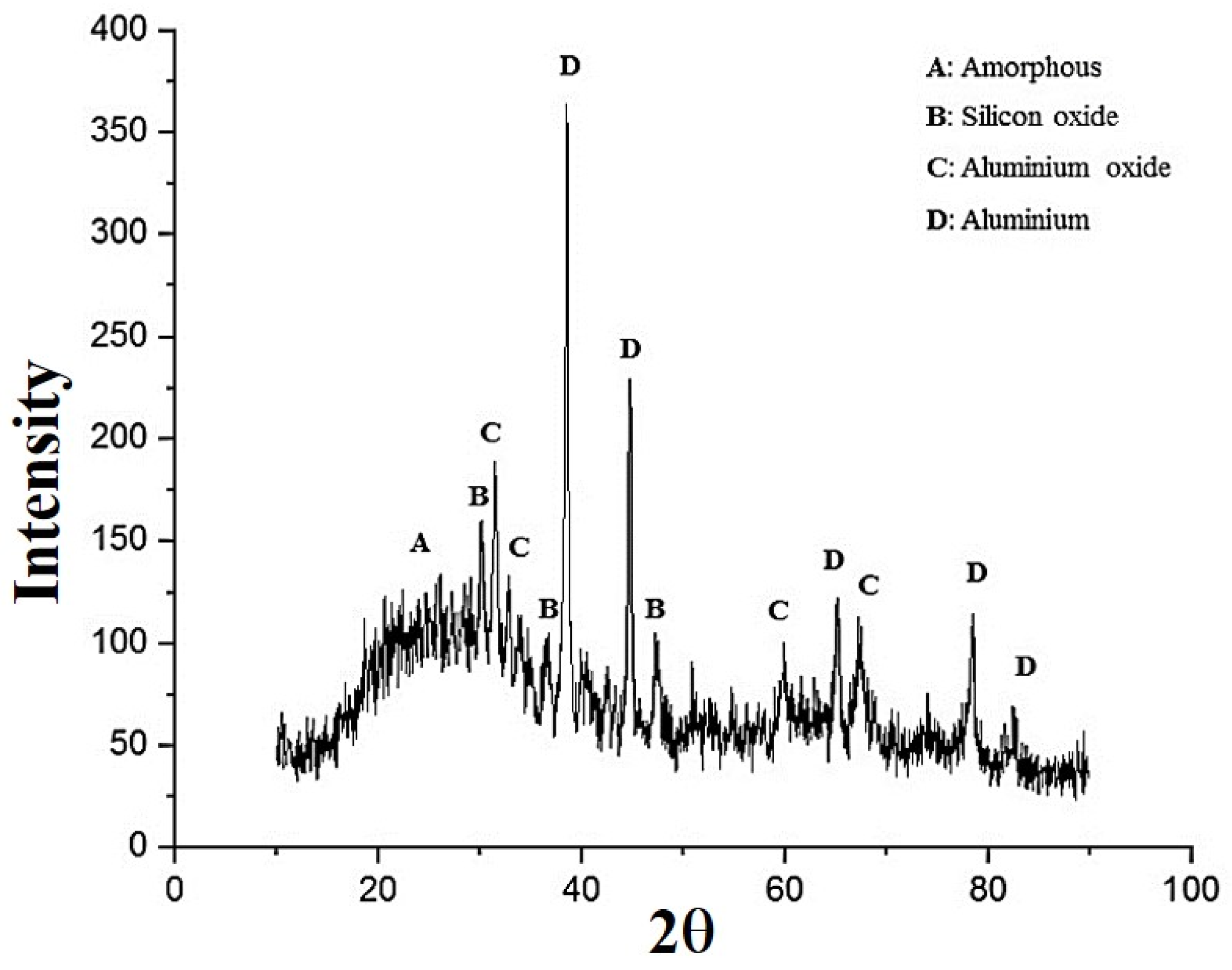
Finally, any possible reaction between the EPPs and the aluminium matrix would improve the binding of the EPP/aluminium alloy matrix. To examine this, EDS and XRD analyses of the interfaces between the two were performed (Figure 11 and Figure 12). The visual detection of a black phase at the interface of some EPPs was mentioned in Figure 8a. Attempts were made to characterize this phase by XRD analysis of a small amount of the phase carefully scratched from the cross section of the sample. The result shown in Figure 12 suggests the presence of the EP amorphous constituents, aluminium, Al2O3, and SiO2. The aluminium is most likely wear debris from the matrix. SiO2 is thought to be due to the crystallization of some of the constituent amorphous silica in the EPP, and Al2O3 may be due to the reduction of oxide constituents of EPP by molten aluminium according to thermodynamically favourable reactions, like those below [46,56,57,58]:
Al l + SiO 2 ( s ) = Al 2 O 3 s + Si ( s   or   sol ) ,   Δ G = ( 310 330 )   kJ/mol   ( T = 700 850   ° C )
EDS line analysis across the interface of an EPP/aluminium alloy matrix is displayed in Figure 11b. Despite the rapid decrease in aluminium concentration when crossing the interface into the EPP, a considerable amount of aluminium is still detected, which points to Al2O3 as the dominant oxide phase in the interface zone. Similar results were observed for samples processed at 725 °C. The similar results have also been shown with other types of porous fillers like SiO2 glass preform [56], fly ash [58], and Al2O3-SiO2 ceramic microspheres [46,57]. XRD and EDS analyses suggested some chemical reactions at the interface of EPPs with the molten aluminium alloy, resulting in the limited reduction of oxide compounds of the EPPs.

3.3. Heat Treatment

Sample F0.8-750 was T6 heat-treated in air or vacuum. The purpose was to examine the improvement in the mechanical properties of the fabricated syntactic foam and to investigate whether long heat treatment in air would render the fabricated syntactic foam brittle. This would be envisaged due to the large specific surface of the fabricated foams, which may result in their excessive oxidation.
A typical microstructure of the struts of the fabricated syntactic foam after T6 heat treatment is shown in Figure 13a. Enlarged portions of the microstructures of the sample in as-fabricated and T6 treated conditions are shown in Figure 13b,c, respectively. It is evident that microstructures of both samples are similar except for the size and shape of the Al2Cu particles detected in the microstructures. In the as-fabricated sample, the precipitates have a fine lamellar morphology (Figure 8c and Figure 13b). However, they show a coarse-less elongated or round shape in the T6 heat-treated sample. It is thought that this could be due to either long aging time used, or incomplete solutionizing, where all the second phases have not been dissolved. In the latter case, the precipitates have gone through a process of fragmentation, spheroidization, and coarsening. Furthermore, the visual appearance of all the samples was similar and no sign of excessive oxidation of the surface was detected on the samples heat-treated in the air.

3.4. Mechanical Properties

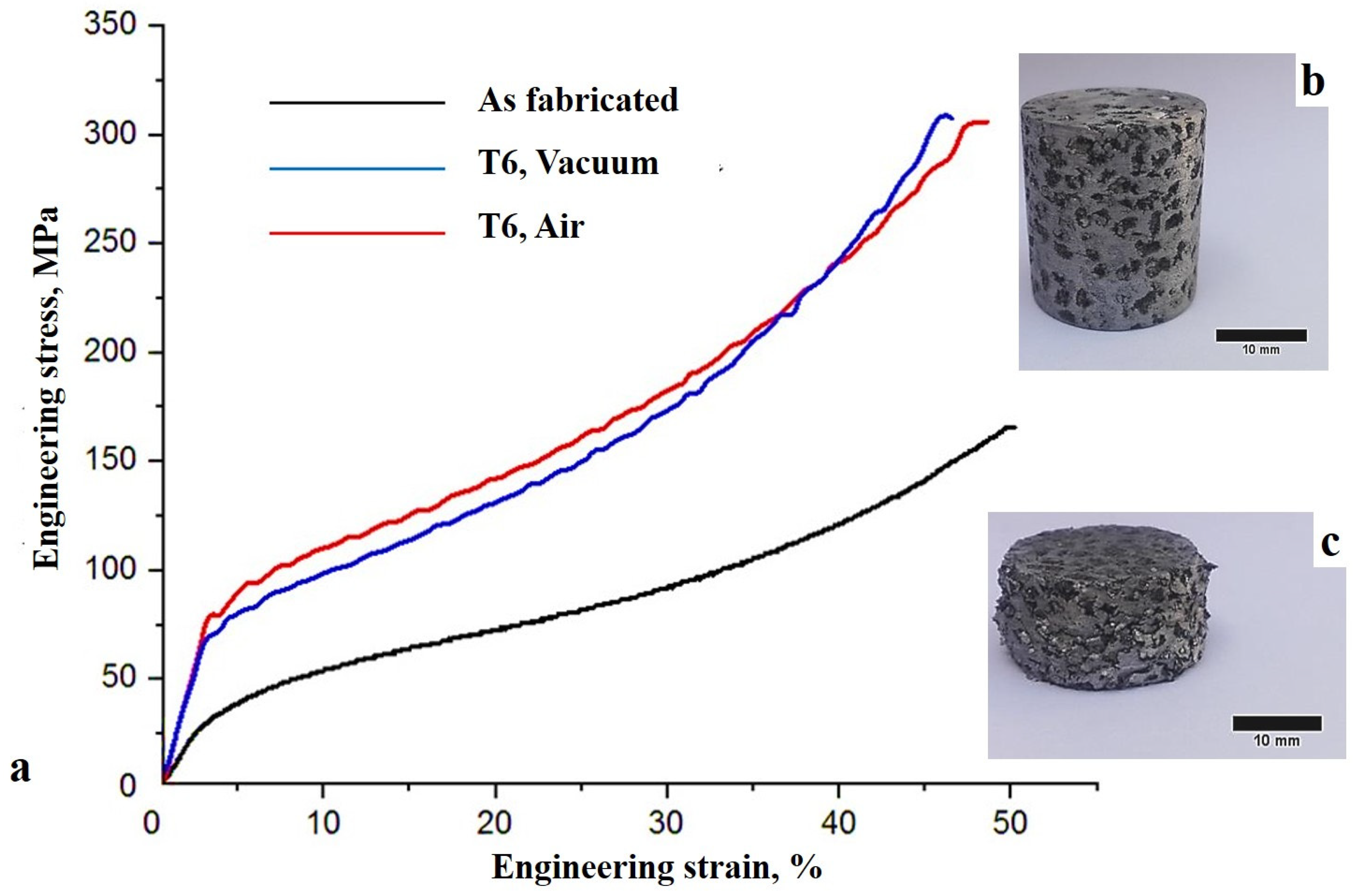
Typical engineering stress-strain curves for as-fabricated and heat-treated F0.8-750 syntactic foams, as well as macrographs of a compression test sample before and after compression test are shown in Figure 14. Clearly, the curves comprise three classic regions of elastic, plateau, and densification regions. The compression properties of the as-fabricated and heat-treated F0.8-750 syntactic foams are tabulated in Table 3.
According to these findings, T6 heat treatment has significantly improved the mechanical properties of the fabricated metal syntactic foams by uniform precipitation of the Al2Cu phase in the metallic matrix, which impedes dislocation mobility. The average compressive strength, plateau stress, and absorption capacity of the air T6 heat-treated foams improved by about 44 MPa, 90 MPa, and 28 MJ/m3, respectively, compared to those of the as-fabricated foams.
The slope of the plateau region in metallic foams is normally very small [6]. However, depending on the relative density of the foam and the type of matrix alloy, work hardening of the matrix alloy may result in a sloped region [59]. Considering the rather high metal fraction of the fabricated syntactic foams, both as-fabricated and heat-treated metal syntactic foams show strain hardening behaviour during their compressive deformation. This is accentuated in heat-treated samples due to the precipitation of Al2Cu particles in the metallic matrix. EPPs will also contribute very slightly to this behaviour compared to an empty cavity porous matrix alloy. At the end of the second stage of deformation, with complete destruction of the cavities, the syntactic foams start to show the compression behaviour of solid metals.
Kadar et al. [4] and Orbulov et al. [60] reported similar results for CP-Al-hollow Al2O3 based spheres and Al99.5-LECA and AlSi9MgMn-LECA syntactic foams, respectively.
Previous research confirms that compressive strength as well as the slope of the plateau region of Al-Cu alloy syntactic foams in both annealed and precipitation hardened conditions are greater than those in Al-Si alloy syntactic foams due to superior work hardening and Al2Cu precipitation in the former [28].
The compressed sample shown in Figure 14c suggests a layer-by-layer mode of deformation, as observed in other types of metal syntactic foams [12]. The uniform deformation of the syntactic foams due to uniformity of the metallic struts, as well as the relative uniformity of the size and distribution of the EPPs used are evident from this figure. Similar densification strains of the compressed foams (40% on average) and the uniform strain of all samples during the compression test suggest the uniform distribution of EPPs in the aluminium matrix.
Surprisingly, vacuum heat-treated samples had slightly inferior mechanical properties than the those treated in air. This is believed to be due to the small delay which occurred before the water quenching for breaking the quartz tubes in the vacuum heat-treated samples. It is believed that a temperature drop during this step would result in some precipitation of solute atoms and, therefore, smaller super-saturation of the aluminium matrix during the subsequent water quenching.

4. Conclusions

In this research, a low-cost method for fabrication of Al-4.3wt.%Cu syntactic foams was examined and the suitable processing conditions were discovered. A low-cost, low-density, commercially available filler material, i.e., Expanded Perlite (EP), and a gas pressure infiltration technique were employed to fabricate the aluminum syntactic foams. The following was drawn from the results of this study.
  • Al-4.3wt.%Cu-expanded perlite (EP) syntactic foams were successfully fabricated using a gas pressure infiltration method, and the effects of infiltration temperature and pressure were examined;
  • The effects of the infiltration temperature on successful infiltration of the melt in the EP particles bed was found to be far greater than that of the infiltration pressure;
  • Complete infiltration is achieved by preferential infiltration of the melt between the mould wall and the EP particles bed, complemented by radial melt infiltration toward the centre of the samples. The full melt infiltration is believed to be mainly affected by the more likely breakage of the aluminium oxide layer on the melt surface and lower melt viscosity at higher temperatures;
  • Atmospheric pressure and 750 °C and were found as the optimum processing conditions for full infiltration of the melt, and resulted in Al-4.3wt.%Cu-EP syntactic foams with an average density of 1.55 g/cm3 and EP volume percentage of 50.3%;
  • The average dendrite cell spacing at the lower and upper part of the syntactic foams was about 41 and 64 μm, respectively, due to directional cooling of the samples;
  • No evidence of extensive directional solidification of columnar grains was observed in the microstructures. The reasons were discussed in terms of the mechanical and thermal effects of EP particles on the growth of the nucleated primary α-aluminium phase;
  • T6 heat treatment improved the average compressive tensile strength, plateau stress, and absorption capacity of the syntactic foams by 98–120%, 77–98%, and 75–100%, respectively;
  • Similar densification strains of the as-fabricated and heat-treated syntactic foams (about 40%), and the uniform strain of all samples during the compression test suggested the uniform distribution of EP particles and metallic struts in the aluminium alloy matrix.

Author Contributions

Conceptualization, B.N.; methodology, B.N. and A.J.D.; validation, B.N. and A.J.D.; analysis, B.N. and A.J.D.; investigation, A.J.D.; supervision, B.N.; writing and editing, B.N.; All authors have read and agreed to the published version of the manuscript.

Funding

This research received no external funding.

Data Availability Statement

The data used in the manuscript are available on request from the corresponding author.

Conflicts of Interest

The authors declare no conflict of interest.

References

  1. Ashby, M.F.; Evans, T.; Fleck, N.A.; Hutchinson, J.; Wadley, H.; Gibson, L. Metal Foams: A Design Guide; Butterworth-Heinemann: London, UK, 2000. [Google Scholar]
  2. Öchsner, A.; Murch, G.E.; De Lemos, M.J. Cellular and Porous Materials: Thermal Properties Simulation and Prediction; John Wiley & Sons: Weinheim, Germany, 2008. [Google Scholar]
  3. Öechsner, A.; Augustin, C. Multifunctional Metallic Hollow Sphere Structures: Manufacturing, Properties and Application; Springer-Verlag: Berlin/Heidelberg, Germany, 2009. [Google Scholar]
  4. Kádár, C.; Kubelka, P.; Szlancsik, A. On the Compressive Properties of Aluminum and Magnesium Syntactic Foams: Experiment and Simulation. Mater. Today Commun. 2023, 35, 106060. [Google Scholar] [CrossRef]
  5. Kemény, A.; Leveles, B.; Bubonyi, T.; Orbulov, I.N. Effect of Particle Size and Volume Ratio of Ceramic Hollow Spheres on the Mechanical Properties of Bimodal Composite Metal Foams. Compos. Part A Appl. Sci. Manuf. 2021, 140, 106152. [Google Scholar] [CrossRef]
  6. Szlancsik, A.; Orbulov, I.N. Compressive Properties of Metal Matrix Syntactic Foams in Uni- and Triaxial Compression. Mater. Sci. Eng. A 2021, 827, 142081. [Google Scholar] [CrossRef]
  7. Kincses, D.B.; Károly, D.; Bukor, C. Production and Testing of Syntactic Metal Foams with Graded Filler Volume. Mater. Today Proc. 2021, 45, 4225–4228. [Google Scholar] [CrossRef]
  8. Bolat, C.; Bilge, G.; Gökşenli, A. An Investigation on the Effect of Heat Treatment on the Compression Behavior of Aluminum Matrix Syntactic Foam Fabricated by Sandwich Infiltration Casting. Mat. Res. 2021, 24, 175–182. [Google Scholar] [CrossRef]
  9. Samvatsar, K.; Dave, H. A Comprehensive Study on Using Fly Ash as Reinforcement Material in Aluminium and Magnesium Based Syntactic Foams. Mater. Today Proc. 2021, 47, 2384–2390. [Google Scholar] [CrossRef]
  10. Al-Sahlani, K.; Broxtermann, S.; Lell, D.; Fiedler, T. Effects of Particle Size on the Microstructure and Mechanical Properties of Expanded Glass-Metal Syntactic Foams. Mater. Sci. Eng. A 2018, 728, 80–87. [Google Scholar] [CrossRef]
  11. Movahedi, N.; Vesenjak, M.; Krstulović-Opara, L.; Belova, I.V.; Murch, G.E.; Fiedler, T. Dynamic Compression of Functionally-Graded Metal Syntactic Foams. Compos. Struct. 2021, 261, 113308. [Google Scholar] [CrossRef]
  12. Movahedi, N.; Murch, G.E.; Belova, I.V.; Fiedler, T. Functionally Graded Metal Syntactic Foam: Fabrication and Mechanical Properties. Mater. Des. 2019, 168, 107652. [Google Scholar] [CrossRef]
  13. Borovinšek, M.; Taherishargh, M.; Vesenjak, M.; Ren, Z.; Fiedler, T. Geometrical Characterization of Perlite-Metal Syntactic Foam. Mater. Charact. 2016, 119, 209–215. [Google Scholar] [CrossRef]
  14. Orbulov, I.N.; Szlancsik, A. On the Mechanical Properties of Aluminum Matrix Syntactic Foams. Adv. Eng. Mater. 2018, 20, 1700980. [Google Scholar] [CrossRef] [Green Version]
  15. Sánchez de la Muela, A.M.; García Cambronero, L.E.; Malheiros, L.F.; Ruiz-Román, J.M. New Aluminum Syntactic Foam: Synthesis and Mechanical Characterization. Materials 2022, 15, 5320. [Google Scholar] [CrossRef] [PubMed]
  16. Movahedi, N.; Fiedler, T.; Taşdemirci, A.; Murch, G.E.; Belova, I.V.; Güden, M. Impact Loading of Functionally Graded Metal Syntactic Foams. Mater. Sci. Eng. A 2022, 839, 142831. [Google Scholar] [CrossRef]
  17. Afolabi, L.O.; Ariff, Z.M.; Saiyid Hashim, S.F.; Alomayri, T.; Mahzan, S.; Kamarudin, K.A.; Dauda Muhammad, I. Syntactic Foams Formulations, Production Techniques, and Industry Applications: A Review. J. Mater. Res. Technol. 2020, 9, 10698–10718. [Google Scholar] [CrossRef]
  18. Bolat, C.; Akgün, I.C.; Gokşenli, A. On the Way to Real Applications: Aluminum Matrix Syntactic Foams. Eur. Mech. Sci. 2020, 4, 131–141. [Google Scholar] [CrossRef]
  19. Duarte, I.; Ferreira, J.M.F. Composite and Nanocomposite Metal Foams. Materials 2016, 9, 79. [Google Scholar] [CrossRef] [Green Version]
  20. S-de-la-Muela, A.M.; Cambronero, L.E.G.; Ruiz-Román, J.M. Molten Metal Infiltration Methods to Process Metal Matrix Syntactic Foams. Metals 2020, 10, 149. [Google Scholar] [CrossRef] [Green Version]
  21. Yang, Q.; Cheng, J.; Wei, Y.; Yu, B.; Miao, Z.; Gao, P. Innovative Compound Casting Technology and Mechanical Properties of Steel Matrix Syntactic Foams. J. Alloys Compd. 2021, 853, 156572. [Google Scholar] [CrossRef]
  22. Kemény, A.; Movahedi, N.; Fiedler, T.; Maróti, J.E.; Orbulov, I.N. The Influence of Infiltration Casting Technique on Properties of Metal Syntactic Foams and Their Foam-Filled Tube Structures. Mater. Sci. Eng. A 2022, 852, 143706. [Google Scholar] [CrossRef]
  23. Taherishargh, M.; Belova, I.V.; Murch, G.E.; Fiedler, T. The Effect of Particle Shape on Mechanical Properties of Perlite/Metal Syntactic Foam. J. Alloys Compd. 2017, 693, 55–60. [Google Scholar] [CrossRef]
  24. Jamshidi-Alashti, R.; Kaskani, M.; Niroumand, B. Semisolid Melt Squeezing Procedure for Production of Open-Cell Al–Si Foams. Mater. Des. 2014, 56, 325–333. [Google Scholar] [CrossRef]
  25. Taherishargh, M.; Sulong, M.A.; Belova, I.V.; Murch, G.E.; Fiedler, T. On the Particle Size Effect in Expanded Perlite Aluminium Syntactic Foam. Mater. Des. 2015, 66, 294–303. [Google Scholar] [CrossRef]
  26. Rohatgi, P.K.; Kim, J.K.; Gupta, N.; Alaraj, S.; Daoud, A. Compressive Characteristics of A356/Fly Ash Cenosphere Composites Synthesized by Pressure Infiltration Technique. Compos. Part A Appl. Sci. Manuf. 2006, 37, 430–437. [Google Scholar] [CrossRef]
  27. Licitra, L.; Luong, D.D.; Strbik, O.M.; Gupta, N. Dynamic Properties of Alumina Hollow Particle Filled Aluminum Alloy A356 Matrix Syntactic Foams. Mater. Des. 2015, 66, 504–515. [Google Scholar] [CrossRef]
  28. Szlancsik, A.; Katona, B.; Bobor, K.; Májlinger, K.; Orbulov, I.N. Compressive Behaviour of Aluminium Matrix Syntactic Foams Reinforced by Iron Hollow Spheres. Mater. Des. 2015, 83, 230–237. [Google Scholar] [CrossRef] [Green Version]
  29. Movahedi, N.; Murch, G.E.; Belova, I.V.; Fiedler, T. Manufacturing and Compressive Properties of Sandwich Foam Tubes Containing Metal Syntactic Foam. Compos. Struct. 2023, 316, 117012. [Google Scholar] [CrossRef]
  30. Movahedi, N.; Murch, G.E.; Belova, I.V.; Fiedler, T. Manufacturing and Compressive Properties of Tube-Filled Metal Syntactic Foams. J. Alloys Compd. 2020, 822, 153465. [Google Scholar] [CrossRef]
  31. Zhang, B.; Zhang, J.; Wang, L.; Jiang, Y.; Wang, W.; Wu, G. Bending Behavior of Cenosphere Aluminum Matrix Syntactic Foam-Filled Circular Tubes. Eng. Struct. 2021, 243, 112650. [Google Scholar] [CrossRef]
  32. Salehi, M.; Mirbagheri, S.M.H.; Jafari Ramiani, A. Efficient Energy Absorption of Functionally-Graded Metallic Foam-Filled Tubes Under Impact Loading. Trans. Nonferr. Met. Soc. China 2021, 31, 92–110. [Google Scholar] [CrossRef]
  33. Shah, A.W.; Ha, S.-H.; Siddique, J.A.; Kim, B.-H.; Yoon, Y.-O.; Lim, H.-K.; Kim, S.K. Microstructure Evolution and Mechanical Properties of Al–Cu–Mg Alloys with Si Addition. Materials 2023, 16, 2783. [Google Scholar] [CrossRef]
  34. Zamani, M.; Belov, I.; Sjölander, E.; Bjurenstedt, A.; Ghassemali, E.; Seifeddine, S. Study on Dissolution of Al2Cu in Al-4.3Cu and A205 Cast Alloys. Metals 2020, 10, 900. [Google Scholar] [CrossRef]
  35. Xu, D.; Zhu, C.; Xu, C.; Chen, K. Microstructures and Tensile Fracture Behavior of 2219Wrought Al–Cu Alloys with Different Impurity of Fe. Metals 2021, 11, 174. [Google Scholar] [CrossRef]
  36. Bannaravuri, P.K.; Birru, A.K. Strengthening of Al-4.5%Cu Alloy with the Addition of Silicon Carbide and Bamboo Leaf Ash. Int. J. Struct. Integr. 2019, 10, 149–161. [Google Scholar] [CrossRef]
  37. Taherishargh, M.; Belova, I.V.; Murch, G.E.; Fiedler, T. Low-Density Expanded Perlite-Aluminium Syntactic Foam. Mater. Sci. Eng. A 2014, 604, 127–134. [Google Scholar] [CrossRef]
  38. Babaee, M.H.; Maleki, A.; Niroumand, B. A Novel Method to Improve Interfacial Bonding of Compound Squeeze Cast Al-Al Macrocomposite Bimetals: Simulation and Experimental Studies. Trans. Nonferr. Met. Soc. China 2019, 29, 1184–1199. [Google Scholar] [CrossRef]
  39. Chandler, H. Heat Treater’s Guide: Practices and Procedures for Nonferrous Alloys; ASM International: New York, NY, USA, 1996. [Google Scholar]
  40. ASM. ASM Handbook: Volume 4: Heat Treating; ASM International: New York, NY, USA, 1991. [Google Scholar]
  41. ASTM E112-13(2021); Standard Test Methods for Determining Average Grain Size. ASTM International: Conshohocken, PA, USA, 2021.
  42. ISO 13314:2011; Mechanical Testing of Metals—Ductility Testing—Compression Test for Porous and Cellular Metals. The International Organization for Standardization: Geneva, Switzerland, 2011.
  43. Sochi, T. Non-Newtonian Flow in Porous Media. Polymer 2010, 51, 5007–5023. [Google Scholar] [CrossRef] [Green Version]
  44. Faridkhou, A.; Tourvieille, J.N.; Larachi, F. Reactions, Hydrodynamics and Mass Transfer in Micro-Packed Beds—Overview and New Mass Transfer Data. Chem. Eng. Process. 2016, 110, 80–96. [Google Scholar] [CrossRef]
  45. Renken, A.; Kiwi-Minsker, L. Advances in Catalysis; Diéguez, M., Núñez, R., Eds.; Academic Press: Cambridge, MA, USA, 2010; Volume 53, Chapter 2. [Google Scholar]
  46. Orbulov, I.N. Metal Matrix Syntactic Foams Produced by Pressure Infiltration—The Effect of Infiltration Parameters. Mater. Sci. Eng. A 2013, 583, 11–19. [Google Scholar] [CrossRef] [Green Version]
  47. Campbell, J. Complete Casting Handbook: Metal Casting Processes, Metallurgy, Techniques and Design, 2nd ed.; Butterworth-Heinemann: Oxford, UK, 2015. [Google Scholar]
  48. Hagart-Alexander, C. Instrumentation Reference Book, 4th ed.; Butterworth-Heinemann: Oxford, UK, 2010; pp. 269–326. [Google Scholar]
  49. Drotning, W.D. Thermal Expansion of Molten Tin, Lead, and Aluminum to 1300/sup 0/K. High Temp. Sci. 1979, 11, 265–276. Available online: https://www.osti.gov/biblio/5186228 (accessed on 15 June 2023).
  50. Huntz, A.M.; Maréchal, L.; Lesage, B.; Molins, R. Thermal Expansion Coefficient of Alumina Films Developed by Oxidation of a FeCrAl Alloy determined by a deflection technique. Appl. Surf. Sci. 2006, 252, 7781–7787. [Google Scholar] [CrossRef]
  51. Ferreira, A.F.; Castro, J.A.D.; Ferreira, L.d.O. Predicting Secondary-Dendrite Arm Spacing of the Al-4.5wt% Cu Alloy During Unidirectional Solidification. Mater. Res. 2017, 20, 68–75. [Google Scholar] [CrossRef] [Green Version]
  52. Grosse, C.U. Advances in Construction Materials; Springer: Berlin/Heidelberg, Germany, 2007. [Google Scholar]
  53. Pfundstein, M.; Gellert, R.; Spitzner, M.; Rudolphi, A. Insulating Materials: Principles, Materials, Applications; Birkhäuser Architecture: Basel, Switzerland, 2008. [Google Scholar]
  54. Kurz, W.; Fisher, D.J.; Rappaz, M. Fundamentals of Solidification, 5th ed.; Trans Tech Publications: Baech, Switzerland, 2023. [Google Scholar]
  55. Somiya, S. Handbook of Advanced Ceramics: Materials, Applications, Processing, and Properties, 2nd ed.; Academic Press: Cambridge, MA, USA, 2013. [Google Scholar]
  56. Liu, W.; Köster, U. Fabrication of Ceramic/Metal Composites by Reduction of Glass SiO2 Preforms in Molten Metals and Alloys. J. Mater. Res. Lett. 1996, 15, 2188–2191. [Google Scholar] [CrossRef]
  57. Balch, D.K.; Dunand, D.C. Load Partitioning in Aluminum Syntactic Foams Containing Ceramic Microspheres. Acta Mater. 2006, 54, 1501–1511. [Google Scholar] [CrossRef]
  58. Rohatgi, P.K.; Guo, R.Q.; Iksan, H.; Borchelt, E.J.; Asthana, R. Pressure Infiltration Technique for Synthesis of Aluminum-Fly Ash Particulate Composite. Mater. Sci. Eng. A 1998, 244, 22–30. [Google Scholar] [CrossRef]
  59. Orbulov, I.N.; Ginsztler, J. Compressive characteristics of metal matrix syntactic foams. Compos. Part A Appl. Sci. Manuf. 2012, 43, 553–561. [Google Scholar] [CrossRef] [Green Version]
  60. Orbulov, I.N.; Szlancsik, A.; Kemény, A.; Kincses, D. Compressive Mechanical Properties of Low-Cost Aluminium Matrix Syntactic Foams. Compos. Part A Appl. Sci. Manuf. 2020, 135, 105923. [Google Scholar] [CrossRef]
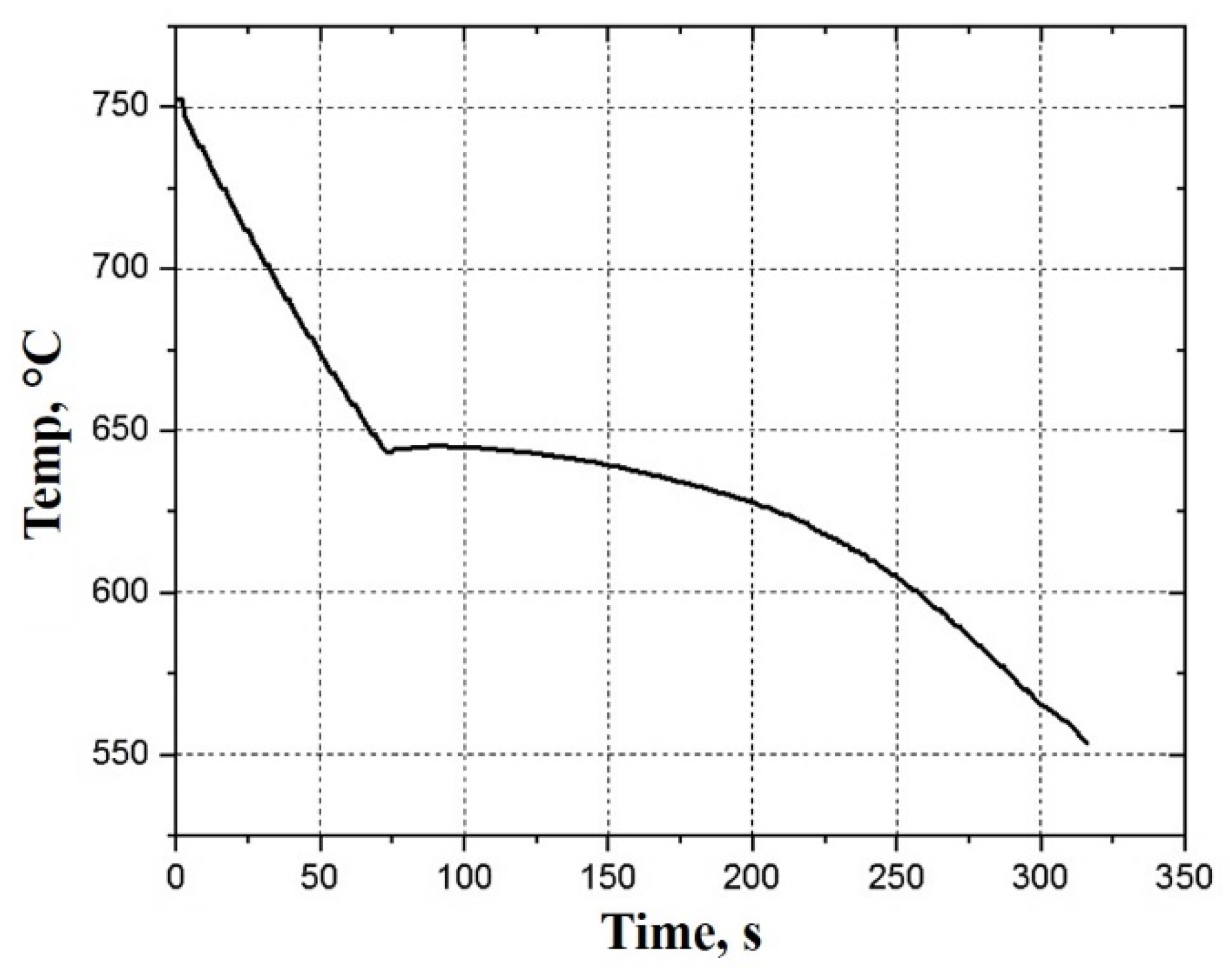
Figure 1. A typical cooling curve of Al-4.3wt.%Cu alloy.
Metals 13 01345 g001
Figure 2. (a) Macrograph of EPPs, and SEM micrographs of (b) a typical EPP and (c) porosities on its surface.
Metals 13 01345 g002
Figure 3. (a) The vacuum melting/pressure infiltration set-up, and schematics of (b) the furnace and (c) the refractory-lined steel moulds used in the experiments.
Metals 13 01345 g003
Figure 4. Simulated viscosity-temperature dependence of Al-4.3wt.%Cu alloy.
Metals 13 01345 g004
Figure 5. Typical Al-4.3wt.%Cu syntactic foam fabricated at infiltration pressure of 0.8 bar and infiltration temperature of (a) 700, (b) 725, and (c) 750 °C.
Metals 13 01345 g005
Figure 6. Schematics of the steps in preferential melt infiltration of the EPPs bed: (a) before melting of the aluminum bar, (b) just after melting of the aluminum bar, (c) preferential infiltration of the melt between the mould wall and the EPPs bed and (d) full infiltration.
Metals 13 01345 g006
Figure 7. Typical syntactic Al-4.3wt.%Cu foam fabricated at infiltration pressure of 1.5 bar and infiltration temperature of (a) 725 and (b) 750 °C, and infiltration pressure of 2.0 bars and infiltration temperature of (c) 725 and (d) 750 °C.
Metals 13 01345 g007aMetals 13 01345 g007b
Figure 8. (a) Macrograph of the cross section of sample F0.8-750, (b,c) microstructure of a strut junction at different magnifications, and (d) SEM of a eutectic region.
Metals 13 01345 g008
Figure 9. Microstructure of the metallic struts of sample F0.8-750: (a) bottom of the sample, (b) schematics of directionally grown dendrites in (a,c) top of the sample, and (d) SEM of the EPPs/aluminium matrix interface.
Metals 13 01345 g009
Figure 10. Schematics of equiaxed growth conditions in (a) a monolithic solid casting and (b) a molten metal infiltrated syntactic foam.
Metals 13 01345 g010
Figure 11. (a) SEM image of the interface between a EPP and Al-4.3 wt.% Cu alloy and (b,c) EDS line analysis across the interface.
Metals 13 01345 g011
Figure 12. XRD spectrum of the black phases at the interface of EPPs and aluminium alloy matrix.
Metals 13 01345 g012
Figure 13. Microstructure of (a) sample F0.8-750 after T6 heat treatment, and enlarged portions of (b) Figure 8c and (c) Figure 13a.
Metals 13 01345 g013
Figure 14. (a) Typical compressive engineering stress-strain curves of F0.8-750 syntactic foams in as-fabricated and heat-treated conditions, and compression test sample (b) before and (c) after compression test.
Metals 13 01345 g014
Table 1. Chemical composition of the alloy (wt.%).
AlCuFeSiMgOther Elements
Bal.4.340.270.310.070.55
Table 2. Infiltration conditions used.
DesignationPressure, BarTemp., °C
F0.8-7000.8700
F0.8-725725
F0.8-750750
F1.5-7001.5700
F1.5-725725
F1.5-750750
F2.0-7002.0700
F2.0-725725
F2.0-750750
Table 3. Average compressive properties of sample F0.8-750.
As-FabricatedT6 in Air (Change, %)T6 in Vacuum (Change, %)
Tensile strength, MPa36.3 ± 0.880.0 ± 1.0 (120%)72.0 ± 1.0 (98%)
Plateau stress, MPa92.1 ± 0.9182.0 ± 1.0 (98%)163 ± 2.0 (77%)
Densification strain, %39.6 ± 0.239.0 ± 0.2 (−1.5%)39.8 ± 0.1 (0.5%)
Absorbed energy, MJ/m327.8 ± 0.355.6 ± 0.6 (100%)48.6 ± 0.3 (75%)
Disclaimer/Publisher’s Note: The statements, opinions and data contained in all publications are solely those of the individual author(s) and contributor(s) and not of MDPI and/or the editor(s). MDPI and/or the editor(s) disclaim responsibility for any injury to people or property resulting from any ideas, methods, instructions or products referred to in the content.