Article

Erosion Mechanism of Carbon Brick in Hearth of 4000 m3 Industrial Blast Furnace

1
State Key Laboratory of Advanced Metallurgy, University of Science and Technology Beijing, Beijing 100083, China
2
School of Metallurgical and Ecological Engineering, University of Science and Technology Beijing, Beijing 100083, China
3
Institute for Metallurgical Engineering and Technology, North China University of Science and Technology, Tangshan 063210, China
*
Authors to whom correspondence should be addressed.
Metals 2023, 13(8), 1371; https://doi.org/10.3390/met13081371
Submission received: 7 July 2023 / Revised: 29 July 2023 / Accepted: 29 July 2023 / Published: 30 July 2023

Abstract

:
After dissection of a large blast furnace, the erosion mechanism of carbon bricks after service in a blast furnace (BF) hearth was studied. Obvious “elephant foot” erosion characteristics emerged in the height direction of the BF. The existing forms of carbon bricks after service were characterized by X-ray diffraction (XRD), scanning electron microscopy–energy dispersive spectroscopy (SEM-EDS), and chemical analysis. The results showed that Zn and iron erosion above and below the taphole was observed in the BF, while iron and Zn erosion acted only as a key factor of carbon brick erosion. The convective heat transfer coefficient in the lower part of the hearth of the BF was large, which increased the temperature of the hearth sidewall, resulting in the increase in the carbon-unsaturation of the molten iron at the sidewall, and intensified erosion to the hearth sidewall. The average pore size (1.083 μm) of the carbon bricks on the hot-face of the hearth sidewall was smaller than the critical size (2.12 μm) of the molten iron that penetrated the pores of the carbon bricks, which was not conducive to the penetration of molten iron.

1. Introduction

The life of a blast furnace is closely correlated to the life of the refractory materials used, and refractory materials with nice erosion resistance are beneficial for the long life of a BF [1,2,3,4,5,6]. The main reason for the erosion of carbon bricks on the hot surface of the hearth is that the carbon components in the carbon bricks are dissolved into the molten iron in contact with them. Therefore, research on the erosion mechanism of carbon refractories in the hearth of a BF is conducive to maintaining the longevity of a BF.
At present, some scholars have studied the erosion mechanism of carbon bricks after service. Deng et al. [7,8] found that the zinc load of a blast furnace was 0.67 kg/t. Because of the cyclic accumulation of zinc, the level of zinc in blast furnace gas was calculated to be 6.85 times that of the zinc load, and the level of zinc was 4.59 kg/t, which was enough to destroy the carbon brick. Jiao et al. [9,10] believed that the dissolution of carbon into molten iron, circulation of molten iron, erosion of carbon bricks by Zn and alkali, and thermal stress were the causation of carbon brick erosion. Guo et al. [11] inferred that Cl, K, Zn, Na, and Fe were the main origins for the severe erosion of carbon refractories. The eroded carbon bricks fell off from the sidewall of the hearth to the molten iron and had been transferred from the molten iron to the deadman. They reached the tuyere with the movement of the coke in the deadman and finally had been burned at the tuyere. Akihiko et al. [12] concluded that the carbon fraction in carbon refractories was gradually replaced by molten iron due to molten iron penetration into the pores of carbon bricks. However, the in-depth study on the erosion mechanism in carbon bricks was lacking.
In this study, the erosion of carbon bricks after service on the sidewall was studied in detail during the overhaul of the BF. Firstly, the composition, mineral phase, and microstructure of the carbon brick after service were studied by using samples taken from different hearth heights in the BF. Then, the convective heat transfer coefficient and the critical pore required for molten iron penetration were calculated correspondingly. Finally, the erosion mechanism of carbon bricks after service was discussed synthetically.

2. Sampling and Analysis

2.1. General Situation of Blast Furnace

After the overhaul of a BF, the carbon bricks after service on the sidewall are sampled. The BF has 4 tapholes and 36 tuyeres. The depth of the deadman is 3.0 m, and the diameter of the hearth is 13.5 m. The BF is put into operation on 8 January 2010, with a service life of 12 years. The distribution of carbon bricks at the bottom of the BF is graphite carbon brick, high-thermal conductivity carbon brick, ultra-micro-pore carbon brick, and ceramic pad from bottom to top. The carbon brick used to build the hearth of the BF is molded small carbon brick. The cold-face is ‘D’ brick, and the hot-face is ‘A’ brick. A layer of high-alumina brick is placed outside the sidewall carbon brick.
The hearth erosion profile of the blast furnace is shown in Figure 1 and Figure 2. The residual thickness of carbon bricks on the height and circumference the BF is uneven. In the circumferential direction, the erosion condition in the taphole area is more serious than that in the non-taphole position, and the erosion condition in the 4 # taphole area is the most serious. The flush of molten iron to the taphole may be one of the key factors of taphole erosion. The 1 # and 3 # tapholes are covered with a mud pack; the 4 # taphole is not covered with mud. In the process of the BF overhaul, it is material to remove the mud pack so that the carbon brick bonded with the mud pack will be lost together with the mud pack and so the residual thickness of the carbon brick at the 1 # and 3 # tapholes is inaccurate. Therefore, when analyzing the residual thickness of the carbon bricks in Figure 2, it is not necessary to consider the 1 # and 3 # tapholes. Therefore, the 4 # taphole is the place with the smallest residual thickness of carbon bricks, which is 248 mm. At its height, the red line in Figure 2 is the erosion curve of carbon bricks on the sidewall. The erosion condition of carbon bricks below the center line of the taphole is more severe than that above the center line of the taphole, and there is obvious “elephant foot” erosion in the BF.

2.2. Introduction of Sampling

The hearth of the BF is divided into the upper and lower areas of the taphole, so these areas are sampled, as shown in Figure 2, to explore the erosion mechanism of carbon bricks in these two areas. In this paper, samples 1 and 2 are obtained from the erosion area of the hearth sidewall at different heights. Sample 1 is located at the 4 # taphole, 1500 mm above the taphole of the blast furnace. Sample 2 is located at the 1 # taphole, 500 mm below the taphole of the blast furnace. From the macroscopic morphology of samples 1 and 2, there is zinc erosion in sample 1 and iron erosion in sample 2. There is some molten iron in the lower area of the taphole, so there may be iron erosion in the carbon brick. In the upper area of the taphole, the zinc oxide contained in the raw material will react to generate zinc vapor, so the carbon brick may have zinc erosion.

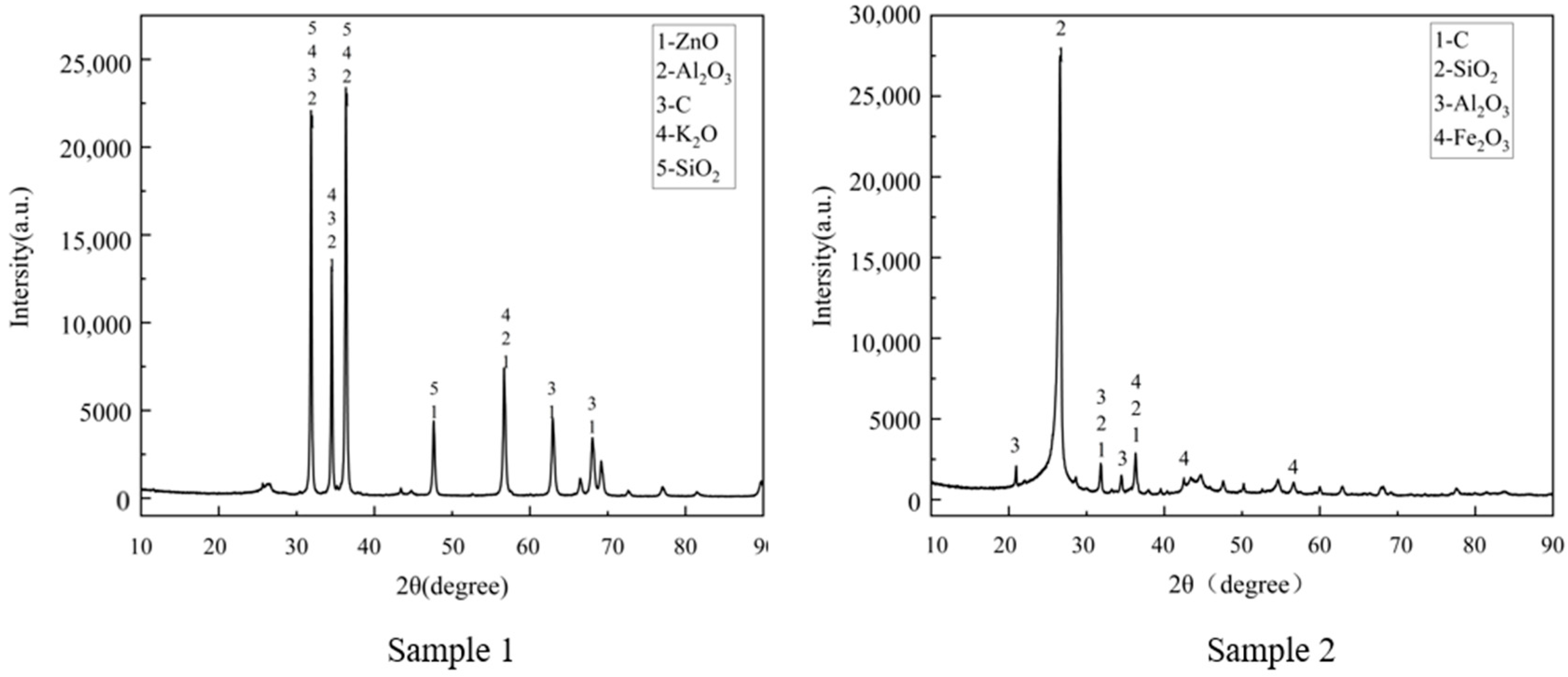
2.3. Analytical Methods

The phases of samples 1 and 2 were tested by XRD (Bruker D8 ADVANCE, Mannheim, Germany). The sample needs to be ground into fine powder (<74 μm) to be analyzed. In the process of XRD analysis, the scanning angle range of samples 1 and 2 is maintained between 10° and 90° (2θ), and the scan speed is 5°/min. Samples 1 and 2 were ground into powder, and the chemical composition was obtained by chemical analysis. A small sample was obtained from samples 1 and 2, respectively, and fixed in the resin. The samples were polished first and then sprayed with gold, and the microstructure and element distribution were observed by SEM-EDS (Zeiss Evo18 Special Edition, 100, Jena, Germany).

3. Results and Discussion

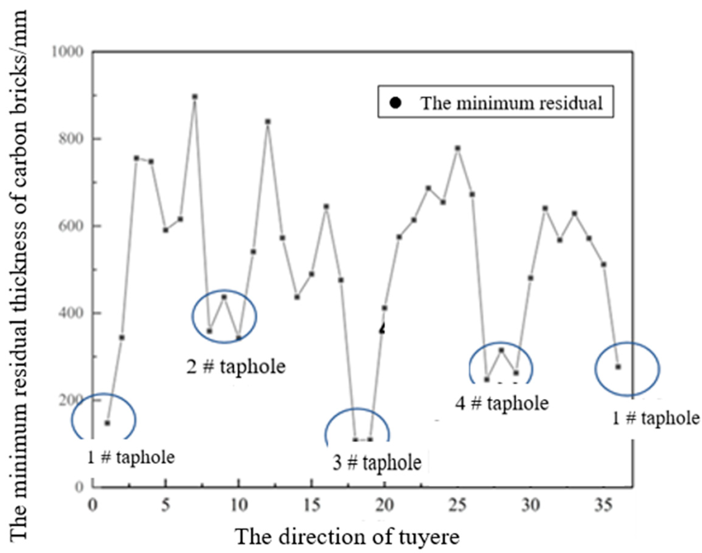
3.1. Investigation of the Carbon Bricks after Service

The macroscopic morphology and XRD of sample 1 and sample 2 are presented in Figure 2 and Figure 3. The macroscopic morphology of sample 1 shows Zn erosion can be seen in it. The macroscopic morphology of sample 2 shows that there is obvious iron erosion on its surface, as shown in Figure 2. XRD analysis of sample 1 shows that carbon bricks contain C, Al2O3, ZnO, SiO2, and K2O phases. XRD analysis of sample 2 shows that carbon bricks mainly contain C, SiO2, Al2O3, and Fe2O3 phases. “A” carbon brick (virgin) mainly contains C, SiO2, and Al2O3. Sample 1 contains ZnO and K2O that are not present in the original carbon bricks, which are formed by the reaction of alkali metals and carbon bricks. Sample 2 contains Fe2O3, which is formed by the reaction of carbon brick and molten iron. Among them, Zinc vapor may enter the carbon brick through the cracks and holes. As zinc vapor continues to deepen, the temperature decreases, and the zinc vapor liquefies and reacts with the CO to form ZnO [13,14,15], as shown in Equation (1). The iron phase in the carbon brick may be oxidized to form iron oxide in the process of overhauling the furnace, as shown in Equation (2).
Zn l + CO = ZnO + C
4 Fe s + 3 O 2 g = 2 Fe 2 O 3
Shown in Table 1 are the chemical constituents of sample 1 and sample 2. The composition of sample 1 is mainly ZnO and C, most of which are ZnO, with a content of 69.69%. The main component of sample 2 is C, which also contains a small amount of ZnO and Fe2O3. The carbon brick above the taphole is mostly eroded by zinc, and the carbon brick below the taphole is mostly eroded by zinc and molten iron. The zinc corrosion phenomenon of sample 1 is much larger than that of sample 2 Fe and Zn are partially miscible in the Fe-Zn phase diagram; the solubility of Zn is 8% in γ-Fe and 46% in α-Fe in BF [16]. Therefore, the zinc content under the center line of the taphole will be greatly reduced, resulting in the weakening of zinc erosion of carbon bricks [17,18]. The erosion in sample 2 may be the penetration of molten iron into carbon brick, then the carbon dissolves with the molten iron, and the carbon bricks are destroyed.
Figure 4 is the micro-morphology of sample 1, which mainly contains C and ZnO. There are many holes and cracks on sample 1, and the cracks are large and long, which can be seen from Figure 4a. The cracks in sample 1 contain many white phases, which are ZnO, and the carbon brick is in a state of fragmentation. The Zn vapor in the BF dissolves in the molten iron. The temperature near the sidewall of the hearth decreases, and the solubility of Zn decreases. It precipitates from the molten iron in the form of gas and enters the interior of the carbon brick. As it continues to deepen, the Zn vapor becomes liquid. It can be seen from Equation (1) that liquid Zn reacts with CO to form ZnO and C when the temperature is less than 1068 °C [19]. The volume expansion of Zn into ZnO is 54% [7]. Combined with the formation of C, new cracks will be formed because of the volume expansion caused by the generated phase.
Figure 5a,b are the micro-morphology of sample 2, which contains C, SiO2, ZnO, and Fe2O3. In Figure 5b, Fe2O3 is formed by the reaction of Fe with oxygen when placed in the air. Because sample 2 is placed in the air for a period of time, the iron contained in sample 2 is oxidized. When the molten iron in the blast furnace contacts the hearth sidewall, carbon will dissolve from carbon bricks to molten iron, resulting in large pores in the carbon brick. The molten iron penetrates into the carbon brick along the pores, and the binder inside the carbon brick will dissolve due to the molten iron, thus destroying the structure and aggravating the erosion [20]. And, the thermal expansion coefficient of molten iron is generally 12 × 10−6 K−1, and the thermal expansion coefficient of carbon brick is 3 × 10⁻⁶ K−1. The change in molten iron expansion is 4 times that of carbon brick expansion, which will produce large stress and destroy the carbon brick. With the gradual aggravation of carbon brick erosion, the thickness of the carbon brick is reduced, the thermal resistance is reduced, the total thermal resistance between the molten iron and the cooling system is reduced, the temperature on the hot-face of the refractory is reduced, and the 1150 °C isothermal line moves to the cold-face, aggravating the erosion and dissolution of molten iron. Combined with Figure 5b–d, it is found that the location of zinc enrichment in carbon bricks is closer to the cold-face of carbon bricks than that of iron, so the erosion of Zn in carbon bricks is deeper than that of molten iron. This may be due to the fact that zinc enters the carbon brick in the form of steam, which has lower requirements for pore size, but the molten iron is affected by surface tension and friction. The pores after Zn erosion will become larger, which will promote the penetration and dissolution of molten iron.

3.2. Calculation of Convective Heat Transfer Coefficient of Carbon Brick

The erosion of the hearth sidewall shows obvious “elephant foot” erosion, and abnormal erosion occurs at the height of about 10 m. The height is measured from the bottom of the BF. During the operation of the blast furnace, there are two main ways of tapping iron: one is to reach the taphole around the sidewall of the hearth, and the other is to reach the taphole from the bottom of the hearth. In the damage investigation of this BF, it was found that the deadman is in a sinking state. With the access of the depth of molten iron, the diameter of the deadman increases first and then decreases [21]. With the access of the convective heat transfer coefficient, the temperature of molten iron at the sidewall of the hearth rises, which leads to the access of carbon-unsaturation in molten iron and accelerates the erosion [22].
The convective heat transfer coefficient equation is [23]:
N u = 0.68 R e 1 / 2 P r 1 / 3
where R e = v . d . ρ μ , P r = μ . C p k , N u = h . d k , v is the flow rate of molten iron, m/s; d is the dimension between the deadman and the carbon brick on the sidewall, m; Cp is the heat capacity of the molten iron, J/(kg·K); ρ is the density of molten iron, kg/(m3); k is the thermal conductivity of the molten iron, W/(m·K); h is the convective heat transfer coefficient, W/(m2·K); μ is the dynamic viscosity, Pa·s.
The equation between the density and temperature of molten iron is [24]:
ρ = 8750 69.6 C 1.15 T
where T is the temperature of molten iron, °C; [C] is the carbon content in the molten iron, %.
The equation between the viscosity and temperature of molten iron is [25]:
μ = 0.3699 × 10 3 e 41.4 × 10 3 R T + 273
where R is the gas constant.
The relationship between thermal conductivity and temperature of molten iron is [26]:
λ = 45.14 exp 0.0013 T
The equation of the flow velocity of the molten iron is:
v = η . V ρ π 4 d 1 2 d 2 2 + π 4 . d 2 2 . ε . t
where V is the volume of the blast furnace, m/s; ε is the porosity of the deadman; d1, and d2 are the diameter of the hearth and deadman, m; t is the time, s; η is the utilization coefficient, t·d−1·m−3.
The calculation formula of the porosity of the deadman is [27]:
ξ = 1 A 2 A 1
where ξ is the porosity of the deadman; A2 is total area of coke and slag-iron; A1 is the area of coke.
The deadman diameter can be calculated by the ratio of the diameter of deadman to the diameter of the hearth after erosion. The ratio can be derived by Equation (9) [28].
η = R 0 L b L i R 0 L b × 100 %
where η is the percentage of the diameter of the deadman to the diameter of the hearth after erosion, %; R0 is the outer diameter of the carbon brick, mm; Lb is the residual thickness of carbon bricks, mm.
By taking out the deadman of the BF and processing the image of the edge area of the deadman root, the declination of the deadman is obtained.
The equation of the distance between the hearth sidewall and the deadman is:
d = L · s i n θ · c o s θ L 0 h t a n α
where L0 is the thickness of the sidewall at the height of the taphole, m; θ is the angle of the taphole, °; α is the declination of the deadman, °; Δh is the height from the location to the taphole centerline, m; L is the length of the taphole, m.
Through calculation, the calculation formula of the convective heat transfer coefficient between the hearth sidewall and molten iron is obtained:
h = 0.68 v · d · ρ μ 1 / 2 . μ · C p k 1 / 3 · k d
Therefore, this part uses the above mathematical model and takes the blast furnace as a reference to select relevant parameters to calculate the convective heat transfer coefficient of the hearth sidewall and evaluate the influence of different parameters on the sidewall temperature. Parameter selection is shown in Table 2.
The convective heat transfer coefficient is 66.43 W/(m2·K). The “elephant foot” area is in the lower part of the BF, and the diameter of the deadman is large. With the access of the distance from the taphole, the convective heat transfer coefficient will increase and promote the formation of “the elephant foot region”. [22]. The convective heat transfer coefficient of the elephant foot region is larger in the lower region of the center line of the taphole. The increase in the convective heat transfer coefficient will access the heat transfer capacity between molten iron at the center of the hearth and molten iron at the sidewall of the hearth [22]. It will accelerate the heat transfer of molten iron from the center of the hearth to the sidewall and increase the temperature of molten iron on the sidewall. Eventually, the erosion condition of the carbon brick here is more serious than that of other heights of the blast furnace, thus forming an “elephant foot” erosion area.

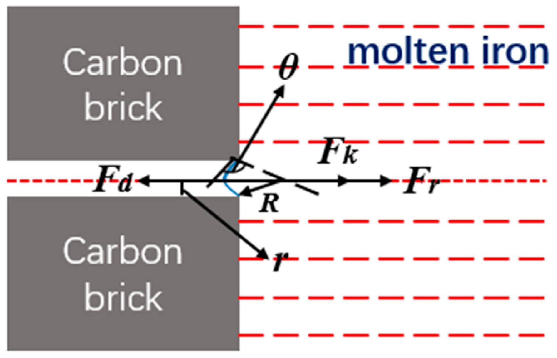
3.3. Erosion of Molten Iron to Carbon Brick

Due to carbon-unsaturation in molten iron of the blast furnace, the dissolution reaction easily occurs. Carbon will continue to dissolve into the molten iron, causing damage to carbon bricks [9]. The thermodynamic study of a molten iron carburizing reaction is the basis for clarifying the iron–carbon interface reaction, which is helpful for further analysis of the iron–carbon interface reaction mechanism [29]. The carburizing reaction of molten iron can be characterized by the two reactions. The relationship between ΔG and T is plotted by FactSage8.2, as shown in Figure 6.
C = C
C + 3 Fe = Fe 3 C
The C + 3Fe = Fe3C reaction is that carbon reacts with molten iron to form Fe3C and dissolves into molten iron.
The C = [C] reaction is a mass transfer process in which carbon directly diffuses into the molten iron.
It can be seen from Figure 6 that the standard Gibbs free energy of the reaction (12) is always lower than that of another reaction, and their Gibbs free energy is one order of magnitude different. As the temperature increases, the standard Gibbs free energy of the reaction (12) increases faster, which proves the reaction (12) is the dominant reaction of the carburizing reaction. Because most of the carbon brick components are carbon, it is considered that the main reason for the erosion is that carbon is dissolved in molten iron.
When the blast furnace is eroded, the molten iron may enter the interior along the pores of the carbon brick, destroying the structure of the carbon brick. Therefore, the mechanism of carbon brick erosion is explored from the perspective of molten iron penetration. As shown in Figure 7, the force diagram of the molten iron penetrating carbon brick is shown. Molten iron penetration is generally determined by three forces. Fd is the pressure of molten iron, Fr is the friction force of molten iron in the falling process, and Fk is the capillary force of pores.
When Fd is greater than the sum of Fr and Fk, the molten iron will form an arc-shaped bulge at the pore entrance, as shown in Figure 8. The pore is a cylindrical pore with a radius of r, and the contact angle between the carbon and the molten iron is θ. The initial radius of molten iron infiltration is R, the surface tension of molten iron is σ, and the surface energy of the infiltrated carbon brick is 4πR2σ. The pore radius of molten iron increases dR, and the surface energy increases to:
dG = 4πσ[(R + dR]2R2] = 8πσR.dR + 4πσR.(dR)2 ≈ 8πσR.dR
According to the law of thermodynamics, the change in surface energy should be the same as the work performed by the external force, that is, the change in surface energy should be the same as the work performed by the additional pressure generated.
d G = δ W 1 = 4 π R 2 P 1 . d R
It can be obtained:
P 1 = 2 σ R
As shown in Figure 7:
r = R c o s 180 θ
where P 1 is the work performed to overcome the surface tension.
The pressure generated by molten iron is opposite to the direction of the surface tension. Therefore, the component force in the direction of pressure can be expressed as:
P 1 = 2 σ R = 2 σ c o s 180 θ r = 2 σ c o s θ r
When the additional pressure is greater than the static pressure generated by the molten iron, molten iron cannot fill this pore. When the additional pressure is less than the static pressure, the molten iron will continue to infiltrate into the pores. When the additional pressure is the same as the value of the static pressure generated by the molten iron, the size of the pore is the critical value, that is, the minimum diameter of the pore so that the molten iron can penetrate the original carbon brick. Assuming that the density of molten iron is ρl, and h is the height of molten iron, g is the gravitational acceleration, the static pressure of liquid iron is ρlgh.
According to the additional pressure equal to the static pressure, the critical radius of the pore where the molten iron can penetrate the carbon brick is calculated. In the BF, the static pressure is the sum of wind pressure (P2) and the gravity of molten iron. Therefore, the critical radius is:
r m i n = 2 σ c o s θ ρ 1 g h + P 2
In general, when the carbon component contained in the molten iron reaches saturation, the wettability between carbon bricks and molten iron is poor, and the contact angle is greater than 90° [30]. For carbon-unsaturated molten iron, the contact angle between them increases with the deepening in the carbon-unsaturation.
The determination of carbon in the hearth of the BF is 4.52%, the temperature of the molten iron is 1510 °C, and the density of the molten iron is 6680 kg/(m3).
The relationship between the surface tension of pure molten iron and temperature is as follows [31]:
σ F e = 2367 0.34 T
For molten iron containing C, with the access of C content, the surface tension decreases, as follows:
d σ d [ C % ] = 3.4
For other components in molten iron, the surface tension has the following relationship [32]:
Fe-Mn :   σ = σ F e 51 · % Mn
Fe-Si :   σ = σ F e 30 · % Si
For molten iron with [Mn%] = 0.12 and [Si%] = 0.42, the surface tension is:
σ F e = 2367 0.34 × 1507 3.4 × 4.52 51 × 0.12 30 × 0.42 = 1821   N · m 1
The salamander depth in the hearth of the BF is 3.0 m, the P2 is 3.88 × 10⁵ Pa, and the wetting angle is 110°. Therefore, the critical pore size of molten iron penetration is calculated as:
r m i n = 2 σ c o s θ ρ 1 g h + P 2 = 2 × 1.821 × c o s 110 180 × π 6680 × 10 × 3.0 + 3.88 × 10 5 = 2.12   μ m
The critical radius of molten iron penetration is 2.12 μm. The average pore size of NMA carbon bricks for the hearth of BF is 1.083 μm. The molten iron does not easily penetrate the original carbon brick. Because of carbon-unsaturation in the molten iron of the BF, carbon is easily dissolved into molten iron, increasing the pores and promoting the penetration of molten iron. In addition, with the increase in temperature, the viscosity of molten iron decreases, the surface tension decreases, and the fluidity increases significantly, which is beneficial to the penetration of molten iron. The pore uniformity inside the carbon brick may be poor, which will also promote the penetration of molten iron. Therefore, molten iron can not only penetrate finer and smaller pores but also penetrate farther distances. These will make the carbon brick erode.

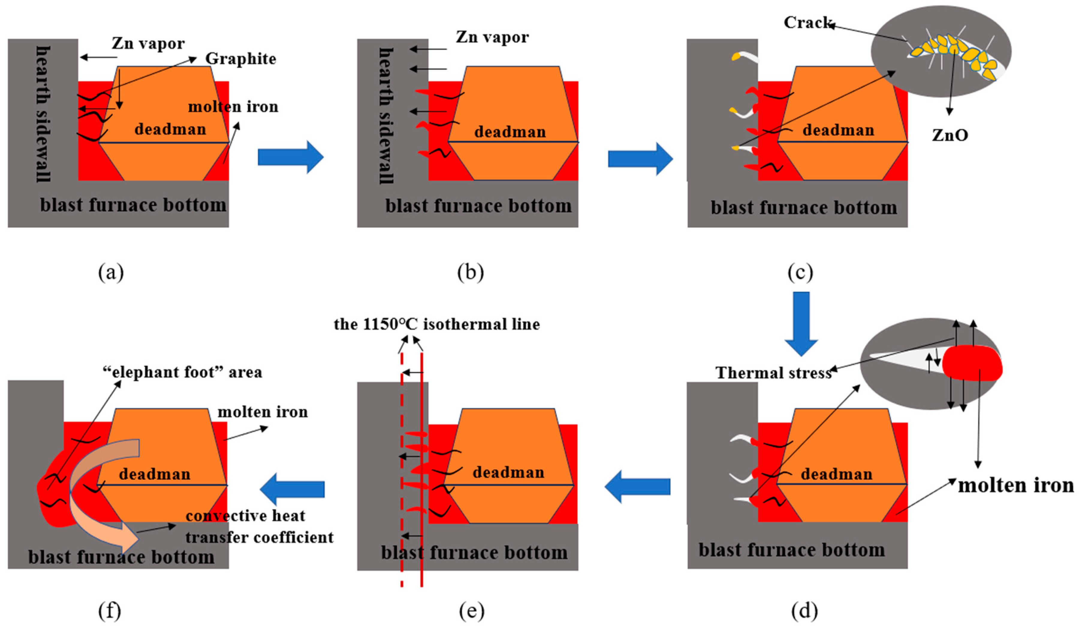
3.4. Analysis of Carbon Brick Erosion Mechanism

As shown in Figure 8, this may be the erosion mechanism of carbon bricks: Zn vapor reaches the hot-face of the carbon bricks on hearth sidewall. Carbon is easily dissolved into molten iron and increases the pore size of the carbon bricks. (Figure 8a). Zn vapor and molten iron enter the carbon brick along the pores of the carbon brick, and the carburization reaction occurs, which destroys the carbon brick (Figure 8b). When the Zn vapor enters the depth of the pores, due to the decrease in temperature, it transforms the liquid and touch with the carbon brick, reacting to form ZnO. This process will be accompanied by expansion and lead to new cracks (Figure 8c). The molten iron enters into the pores. The thermal expansion coefficient of the molten iron is about 4 times that of the carbon brick; therefore, the internal pores will be squeezed by molten iron (Figure 8d). With the gradual aggravation of carbon brick erosion, the 1150 °C isothermal line moves to the cold-face, which will aggravate the erosion and dissolution of the carbon brick (Figure 8e). The shape of the deadman in the BF is shown in Figure 8 [17]. The convective heat transfer coefficient at the lower sidewall of the hearth is larger, which will transfer the heat of molten iron in the hearth center to the molten iron on the sidewall of the BF, increase the carbon-unsaturation in the molten iron on the sidewall, aggravating the above erosion process. The erosion mechanism of carbon bricks with a taphole can be extended also in the zones without a taphole. The main difference lies in the convective heat transfer. According to Equation (11), near the taphole, the convective heat transfer coefficient is larger than far from the taphole, due to a high flow velocity of the molten iron in the taphole area. Therefore, the taphole areas are affected by more serious erosion that creates the characteristic “elephant foot” morphology. (Figure 8f).

3.5. Suggestions for Operation and Construction of BF

In order to realize the long life of a BF, reduce costs, and improve product quality, some suggestions are put forward.
  • Since the molten iron in the BF is unsaturated in carbon, the carbon content in the carbon brick will dissolve with the molten iron. Therefore, it is possible to try to use ‘B’ carbon bricks [29] (carbon bricks with carbon content lower than ‘A’) instead of A carbon bricks in the hearth sidewall area.
  • The molten iron may enter the depth of the carbon brick along the cracks and pores. Therefore, the sidewall of the hearth may be replaced by ultra-micro-porous carbon bricks.
  • Because the convective heat transfer coefficient has a significant effect on the formation of “elephant foot” erosion, increasing the depth of the salamander so that the deadman does not contact the bottom of the BF will reduce its impact [22].
  • Reducing the Zn of raw materials into the furnace will appropriately increase the temperature of the BF so that the zinc evaporates, moves upward, and generates ZnO, which is discharged with the furnace dust [7].

4. Conclusions

To understand the erosion mechanism of carbon bricks in the hearth of the BF, the carbon bricks appearing in the severe erosion area were sampled, and their hot surfaces and interiors were observed by SEM-EDS. The results of these observations are:
(1) In the circumferential and height directions of the BF, the residual thickness of the hearth sidewall is not uniform. In the height direction, the height of the most serious erosion of the sidewall of the hearth is 10 m, which shows obvious abnormal erosion characteristics of the “elephant foot” area. In the circumferential direction of the BF, the erosion degree in the taphole area is more serious than that in the non-taphole area.
(2) Carburizing reaction and the penetration of molten iron will lead to the erosion of carbon bricks. The reaction of zinc into the carbon brick will lead to the occurrence of expansion and destroy the morphology of the carbon brick. Therefore, iron erosion is the main reason for blast furnace carbon brick erosion, and Zn erosion is a key reason for BF carbon brick erosion.
(3) The convective heat transfer coefficient is 66.43 W/(m2·K1), which plays an important role in the “elephant foot” area of the BF. With the increase in the convective heat transfer coefficient, the temperature of the molten iron on the hearth sidewall increases, which increases the carbon-unsaturation in molten iron, resulting in the corrosion of carbon bricks on the hearth sidewall.
(4) The critical radius of molten iron penetrating the carbon brick is 2.12 μm. When the carbon brick is eroded, the diameter of the pores increases, and the molten iron will enter the interior of the carbon brick along the pores, destroying the structure of the carbon brick.

Author Contributions

Conceptualization, C.W. and J.C.; methodology, C.W.; software, J.Z.; validation, Y.D., G.Z. and M.S.; formal analysis, Y.D.; investigation, G.Z.; resources, J.Z.; data curation, M.S.; writing—original draft preparation, J.C.; writing—review and editing, C.W.; visualization, C.W.; supervision, J.Z.; project administration, Y.D.; funding acquisition, G.Z. All authors have read and agreed to the published version of the manuscript.

Funding

This work was financially supported by the National Natural Science Foundation for Young Scientists China (No. 52204334). (The funder: Cui Wang; The funding number: 52204334).

Data Availability Statement

Not applicable.

Conflicts of Interest

The authors declare no conflict of interest.

References

  1. Xu, R.; Zhang, J.; Li, Z.; Zhao, Y. Corrosion Behavior of Alumina Containing Refractory in Blast Furnace Hearth by CaO–SiO2–MgO–Al2O3–Cr2O3 Slags. ISIJ Int. 2019, 59, 1933. [Google Scholar] [CrossRef] [Green Version]
  2. Gao, K.; Jiao, K.X.; Zhang, J.L.; Zhang, L.; Wang, C.; Gong, W.M.; Zheng, J.X.; Zhang, H.B. Dissection Investigation of Forming Process of Titanium Compounds Layer in the Blast Furnace Hearth: Ironmaking. ISIJ Int. 2020, 60, 2385. [Google Scholar] [CrossRef]
  3. Takatani, K.; Inada, T.; Takata, K. Mathematical Model for Transient Erosion Process of Blast Furnace Hearth. ISIJ Int. 2001, 41, 1139–1145. [Google Scholar] [CrossRef]
  4. Wang, C.; Cao, J.; Zhang, J.; Guo, Z.; Jiao, K.; Zhao, Y. Thermal conductivity of alumina-carbon composite brick and its related phase analysis in a dissected blast furnace. Met. Res. Technol. 2023, 120, 216. [Google Scholar] [CrossRef]
  5. Brulin, J.; Gasser, A.; Rekik, A.; Blond, E.; Roulet, F. Thermomechanical modelling of a blast furnace hearth. Constr. Build. Mater. 2022, 326, 126833. [Google Scholar] [CrossRef]
  6. Jiang, Z.; Guo, T.; Hu, D.; Xie, M.; Liu, B.; Yao, S. Consideration of long campaign based on analysis of 4038 m3 blast-furnace hearth core investigation. Met. Res. Technol. 2023, 120, 213. [Google Scholar] [CrossRef]
  7. Deng, Y.; Lyu, Q.; Zhang, J.; Jiao, K. Erosion of Carbon Brick by Zinc in Hearth of Blast Furnace. ISIJ Int. 2019, 60, 226–232. [Google Scholar] [CrossRef] [Green Version]
  8. Deng, Y.; Zhang, J.-L.; Jiao, K.-X. Dissolution Mechanism of Carbon Brick into Molten Iron. ISIJ Int. 2018, 58, 815. [Google Scholar] [CrossRef] [Green Version]
  9. Jiao, K.; Zhang, J.; Liu, Z.; Kuang, S.; Liu, Y. Dissection Investigation of Ti(C,N) Behavior in Blast Furnace Hearth during Vanadium Titano-magnetite Smelting. ISIJ Int. 2017, 57, 48. [Google Scholar] [CrossRef] [Green Version]
  10. Jiao, K.; Fan, X.; Zhang, J.; Wang, K.; Zhao, Y. Corrosion behavior of alumina-carbon composite brick in typical blast furnace slag and iron. Ceram. Int. 2018, 44, 19981. [Google Scholar] [CrossRef]
  11. Guo, Z.; Zhang, J.; Jiao, K.; Zong, Y.; Wang, Z. Occurrence State and Behavior of Carbon Brick Brittle in a Large Dissected Blast Furnace Hearth. Steel Res. Int. 2021, 92, 2100273. [Google Scholar] [CrossRef]
  12. Shinotake, A.; Nakamura, H.; Yadoumaru, N.; Morizane, Y.; Meguro, M. Investigation of Blast-Furnace Hearth Sidewall Erosion by Core Sample Analysis and Consideration of Campaign Operation. ISIJ Int. 2003, 43, 321. [Google Scholar] [CrossRef] [Green Version]
  13. Deng, Y.; Liu, R.; Jiao, K.X.; Ma, H.X.; Guo, Z.Y.; Meng, S.; Song, M.B. Iron-Carbon Interface Phenomenon and Reaction Be-havior Analysis in Blast Furnace Hearth. ISIJ Int. 2023, 63, 253. [Google Scholar] [CrossRef]
  14. Wang, X.-F.; Zhai, Q.-J. Corrosion mechanism research and microstructure analysis of Baosteel No. 3 blast furnace hearth. J. Iron Steel Res. Int. 2017, 24, 1016. [Google Scholar] [CrossRef]
  15. Cao, J.; Wang, C.; Zhang, J.; Yang, X.; Xu, J.; Zhang, G. Formation mechanism of the brittle layer in carbon brick of blast furnace hearth. Steel Res. Int. 2023. in Press. [Google Scholar] [CrossRef]
  16. Tian, R.Z. Zinc Alloy; Central South University Press: Changsha, China, 2010; p. 31. (In Chinese) [Google Scholar]
  17. Song, Q.J.; Ning, X.J.; Zhang, J.L.; Jiao, K.X.; Wang, C. Influences of zinc on the erosion of blast furnace hearth refractories. Mater. Sci. Technol. Conf. Exhib. 2017, 2017, 660–667. [Google Scholar]
  18. Jiao, K.X.; Zhang, J.L.; Zuo, H.B.; Liu, Z.J. Calculation Analysis of Zinc Dissolution Behaviors of the Slag-Iron in Blast Furnaces. J. Northeast. Univ. Nat. Sci. 2014, 35, 383. (In Chinese) [Google Scholar]
  19. Niu, Q.; Cheng, S.S.; Xu, W.X.; Niu, W.J. Microstructure and Phase of Carbon Brick and Protective Layer of a 2800 m3 Industrial Blast Furnace Heart. ISIJ Int. 2019, 59, 1776. [Google Scholar] [CrossRef] [Green Version]
  20. Fan, X.; Zhang, J.; Jiao, K.; Zhang, J.; Wang, K. Distribution of harmful elements in dissected 125 m3 blast furnace. Can. Met. Q. 2019, 58, 400–409. [Google Scholar] [CrossRef]
  21. Wang, X.B.; Wang, J.G.; Liang, D.; Meng, S.; Jiao, K.X.; Zhang, J.L. Analysis on deadman behavior in hearth and cause of lon-gevity of large blast furnace. Iron Steel 2023, 1. (In Chinese) [Google Scholar] [CrossRef]
  22. Jiao, K.; Zhang, J.; Hou, Q.; Liu, Z.; Wang, G. Analysis of the Relationship between Productivity and Hearth Wall Temperature of a Commercial Blast Furnace and Model Prediction. Steel Res. Int. 2017, 88, 1600475. [Google Scholar] [CrossRef]
  23. Zhang, X.Z. Metallurgy Transmission Principle; Metallurgical Industry Press: Beijing, China, 1988; p. 169. (In Chinese) [Google Scholar]
  24. Jones, N.W. Kinetics of carbon dissolution in Fe-C alloy at 1550 °C. Ironmak. Steelmak. 1998, 25, 460. [Google Scholar]
  25. Kawai, Y.; Shiraishi, Y. Handbook of Physico-Chemical Properties at High Temperatures; The iron and steel institute of Japan: Tokyo, Japan, 1988. [Google Scholar]
  26. Jiao, K.; Zhang, J.; Zuo, H.; Xu, R.; Hong, J. Calculation and Analysis the Influence on the Cooling Water Velocity and Hot Metal Circulation to the Long Life BF. J. Mater. Sci. Eng. 2014, 5, 589. [Google Scholar] [CrossRef]
  27. Meng, S.; Jiao, K.; Zhang, J.; Zong, Y.; Zhang, L.; Ma, H.; Guo, Z. Dissection study of the deadman in a commercial blast furnace hearth. Fuel Process. Technol. 2021, 221, 106916. [Google Scholar] [CrossRef]
  28. Zhang, L.; Zhang, J.; Jiao, K.; Zou, Z.; Zhao, Y. Observation of Deadman Samples in a Dissected Blast Furnace Hearth. ISIJ Int. 2019, 59, 1991. [Google Scholar] [CrossRef] [Green Version]
  29. Wang, C.; Zhang, J.; Chen, W.; Li, X.; Jiao, K.; Pang, Z.; Wang, Z.; Wang, T.; Liu, Z. Comparative Analysis on the Corrosion Resistance to Molten Iron of Four Kinds of Carbon Bricks Used in Blast Furnace Hearth. Metals 2022, 12, 871. [Google Scholar] [CrossRef]
  30. Deng, Y.; Liu, R.; Jiao, K.; Chen, Y. Wetting behavior and mechanism between hot metal and carbon brick. J. Eur. Ceram. Soc. 2021, 41, 5740. [Google Scholar] [CrossRef]
  31. Nakashima, K.; Mori, K. Interfacial Properties of Liquid Iron Alloys and Liquid Slags Relating to Iron- and Steel-making Processes. ISIJ Int. 1992, 32, 11. [Google Scholar] [CrossRef] [Green Version]
  32. Chung, Y.; Cramb, A.W. Dynamic and equilibrium interfacial phenomena in liquid steel-slag systems. Met. Mater. Trans. B 2000, 31, 957–971. [Google Scholar] [CrossRef]
Figure 1. Erosion profile of blast furnace hearth.
Metals 13 01371 g001
Figure 2. Sampling positions of eroded carbon bricks on hearth sidewall.
Metals 13 01371 g002
Figure 3. XRD results of the carbon bricks after service.
Metals 13 01371 g003
Figure 4. SEM and EDS results of sample 1. (a) SEM results; (be) EDS results of Zn, K, Na, and O elements.
Metals 13 01371 g004
Figure 5. SEM and EDS results of sample 2. (a,b) SEM results; (c,d) EDS results of Fe, Zn elements.
Metals 13 01371 g005
Figure 6. The relationship between standard Gibbs free energy of carburizing reaction and temperature.
Metals 13 01371 g006
Figure 7. Stress analysis of molten iron penetration.
Metals 13 01371 g007
Figure 8. Carbon brick erosion mechanism diagram. (a,b) Initial stage of erosion; (ce) Aggravating stage of erosion; (f) Late stage of erosion.
Metals 13 01371 g008
Table 1. Chemical composition of the carbon bricks after service, %.
ParameterCZnOSiO2K2OAl2O3Fe2O3Na2OCl
Sample 122.2569.692.141.710.761.690.270.3
Sample 283.843.346.240.241.293.030.120.05
Table 2. Parameter value.
ParameterUnitValueParameterUnitValue
μPa·s6.0 × 10−3Lm3
ηt/(d·m3)2.26θ°10
ρKg/(m3)6680α°45
CpJ/(kg·K)610d1m13.5
λ W/(m·K)6.88T d2m10.5
Vm34000L0m1.6
RJ/(mol·K)8.314hm0.71
ε-0.3vm2.76 × 10−4
Disclaimer/Publisher’s Note: The statements, opinions and data contained in all publications are solely those of the individual author(s) and contributor(s) and not of MDPI and/or the editor(s). MDPI and/or the editor(s) disclaim responsibility for any injury to people or property resulting from any ideas, methods, instructions or products referred to in the content.

