
Electrohydraulic Crimping of Tubes within Rings

Abstract
:1. Introduction
2. Equipments
2.1. Material
2.2. Pulsed Current Generator
2.3. Crimping System
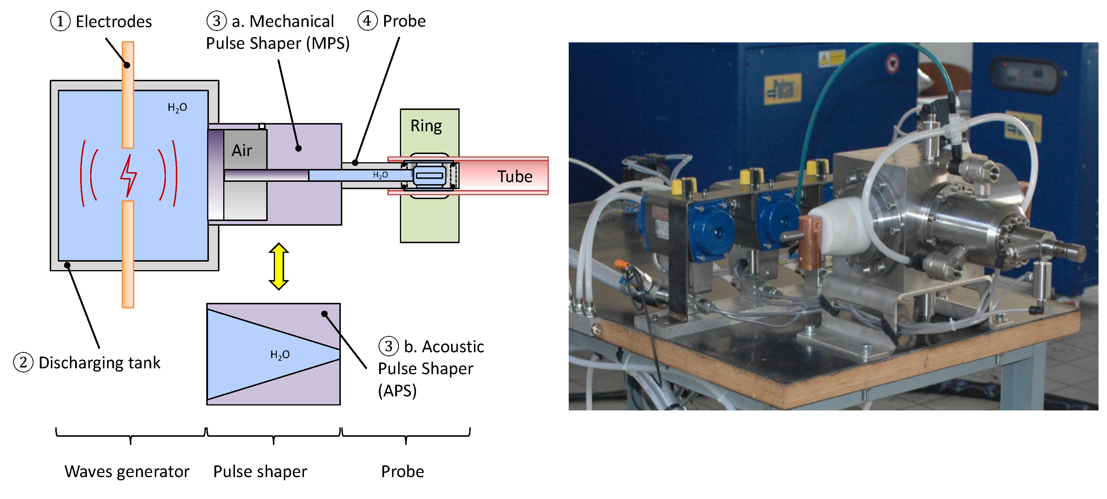
2.4. Waves Generator
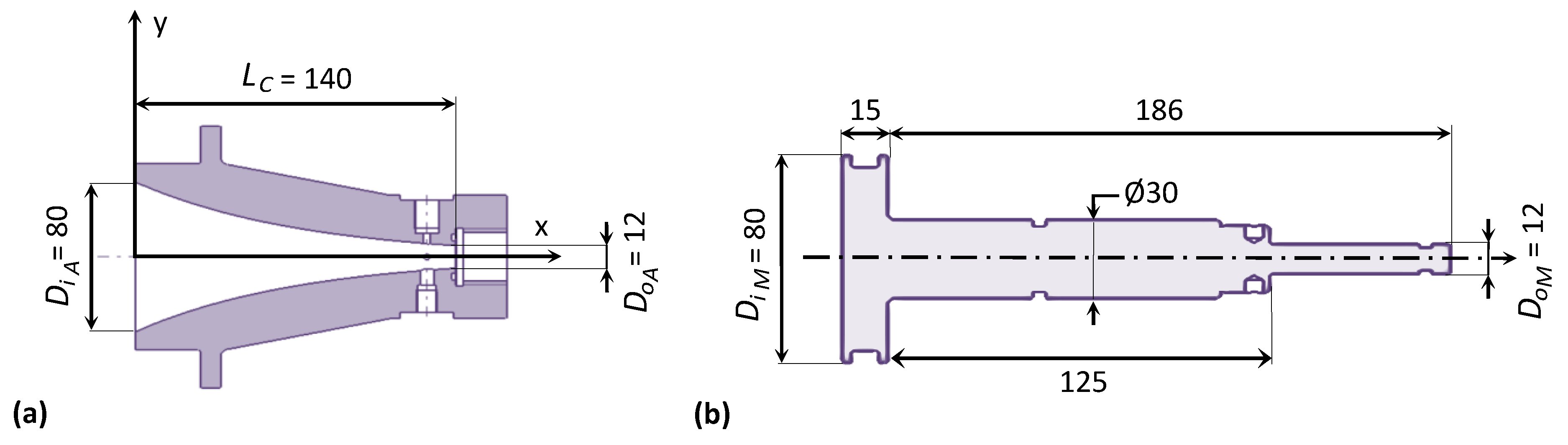
2.5. Acoustic and Mechanical Pulse Shapers
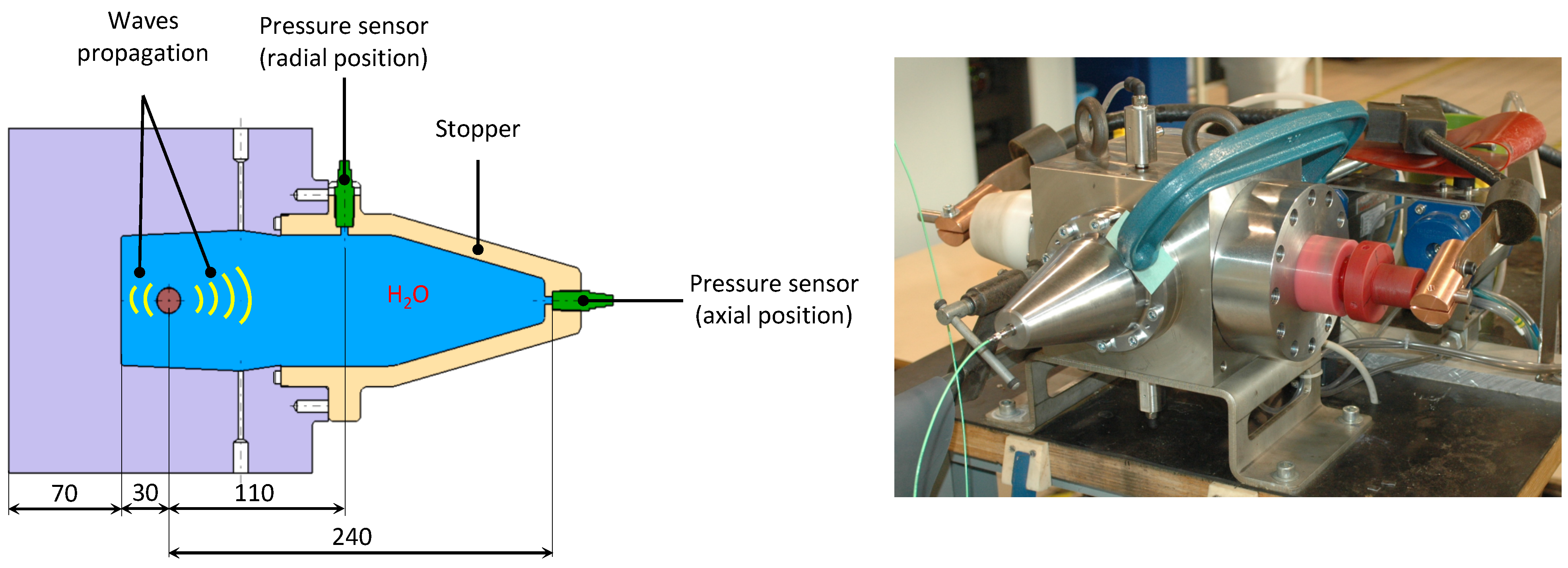
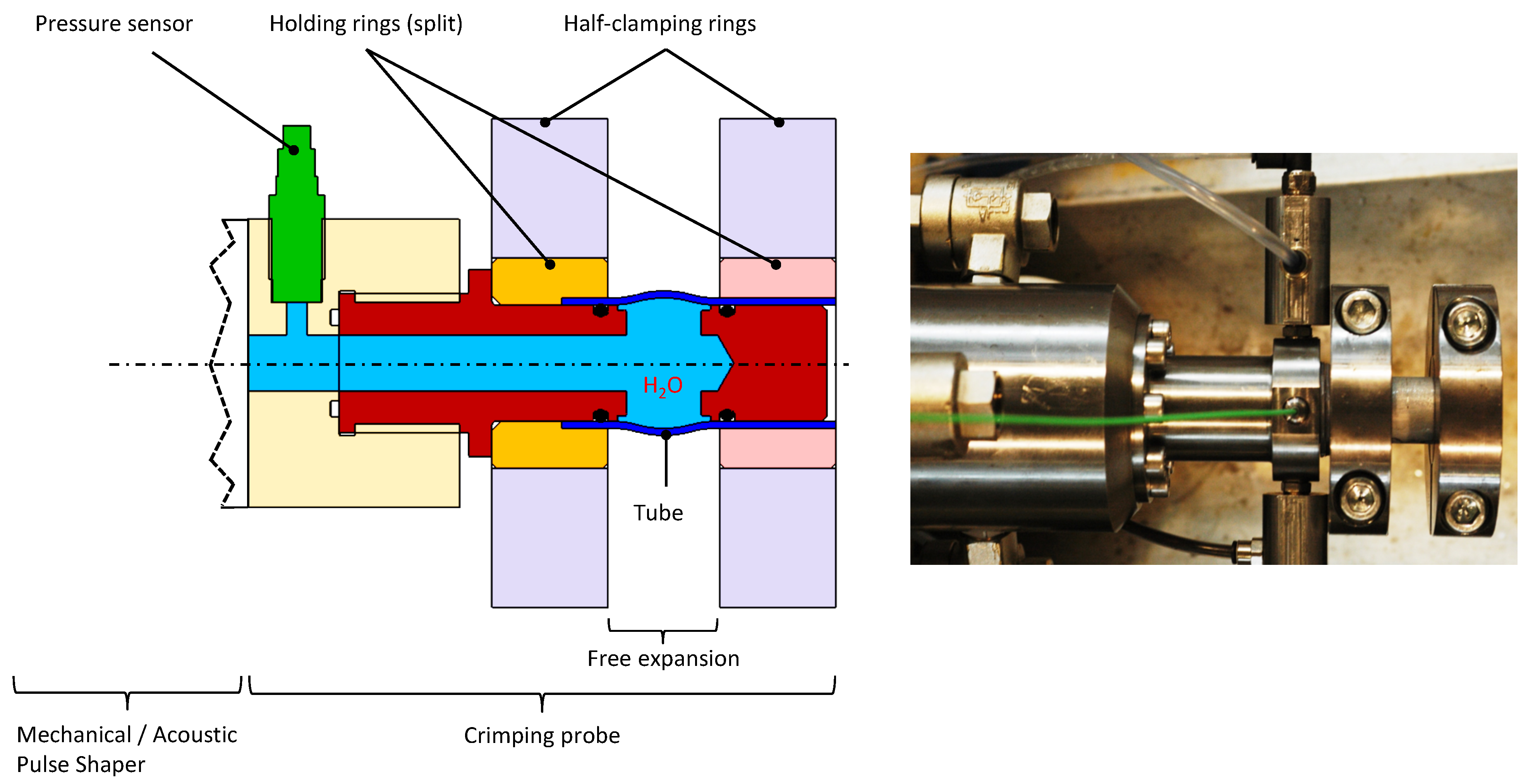
2.6. Crimping Probe
2.7. Means of Measurement
3. Methods
3.1. Experimental Set-Up for Measuring the Input/Output Law of the Waves Generator
3.2. Experimental Set-Up for Expansion Pressure Measurement
3.3. Experimental Set-Up for Strain Rate Measurements during a Free Expansion Test
3.4. Experimental Set-Up for Crimping Tests
4. Results and Discussion
4.1. Input/Output Waves Generator Law
- the more the allowable inter-electrodes distance, the more the discharge energy;
- the more the inter-electrodes distance, the more the dispersion;
- for a given energy, the maximum intensity of the current decreases as the inter-electrodes distance increases.
4.2. Strain Rate Measurement
- only one pressure wave is present;
- the pressure signal is no longer pseudo-periodic, as it was the case when the crimping probe was equipped with a thick ring (Figure 12), but rather trapezoidal;
- this signal includes a phase of rise that seems to be almost linear but disturbed then a pseudo-plateau and finally a phase of linear decay.
4.3. Crimping Tests
- With APS, the measured maximum force is less than 1 kN and no trend can be observed regarding the launch gap.
- With the MPS, for pressures lower than those applied with APS, the maximum push-out force reach up to 7 kN. This seems to show that the intensity of the pressure wave is not enough to achieve a crimping, it is necessary that the load is applied for a sufficiently long time. The MPS, which exploits secondary waves rather than the primary shock wave, is therefore logically more efficient.
- With MPS we find that the lower the launch gap is, the better the crimping is.
5. Conclusions
Author Contributions
Funding
Institutional Review Board Statement
Informed Consent Statement
Data Availability Statement
Acknowledgments
Conflicts of Interest
Abbreviations
| APS | Acoustic Pulse Shaper |
| MPS | Mechanical Pulse Shaper |
Appendix A
References
- Marré, M.; Rautenberg, J.; Tekkaya, A.E.; Zabel, A.; Biermann, D.; Wojciechowski, J.; Przybylski, W. An experimental study on the groove design for joints produced by hydraulic expansion considering axial or torque load. Mater. Manuf. Process. 2012, 27, 545–555. [Google Scholar] [CrossRef]
- Jawad, M.H.; Clarkin, E.J.; Schuessler, R.E. Evaluation of Tube-to-Tubesheet Junctions. J. Press. Vessel Technol. 1987, 109, 19–26. [Google Scholar] [CrossRef]
- Mori, K.-I.; Bay, N.; Fratini, L.; Micari, F.; Tekkaya, A.E. Joining by plastic deformation. CIRP Ann.-Manuf. Technol. 2013, 62, 673–694. [Google Scholar] [CrossRef]
- Varis, J.P. The suitability of round clinching tools for high strength structural steel. Thin-Walled Struct. 2002, 40, 225–238. [Google Scholar] [CrossRef]
- Merah, N.; Al-Zayer, A.; Shuaib, A.; Arif, A. Finite element evaluation of clearance effect on tube-to-tubesheet joint strength. Int. J. Press. Vessel. Pip. 2003, 80, 879–885. [Google Scholar] [CrossRef]
- Oppenheimer, P.H. Rolling tubes in boiler plates. J. Am. Soc. Nav. Eng. 1927, 39, 417–426. [Google Scholar]
- Maxwell, C.A. Practical aspects of making expanded joints. Trans. ASME 1943, 65, 506–522. [Google Scholar] [CrossRef]
- Kohlpaintner, W.R. Calculation of hydraulically expanded tube-To-Tubesheet joints. J. Press. Vessel Technol. Trans. ASME 1995, 117, 24–30. [Google Scholar] [CrossRef]
- Podhorsky, M.; Krips, H. Hydraulic Expansion of Tubes. VGB Kraftwerkstechnik 1979, 1, 77–83. [Google Scholar]
- Goodier, J.N.; Schoessow, G.J. The holding power and hydraulic tightness of expanded tube joints: Analysis of the stress and deformation. Trans. ASME 1943, 65, 489–496. [Google Scholar] [CrossRef]
- Yokell, S. Expanded, and welded-and-expanded tube-to-tubesheet joints. J. Press. Vessel Technol. Trans. ASME 1992, 114, 157–165. [Google Scholar] [CrossRef] [Green Version]
- Wang, H.F.; Sang, Z.F. Effect of geometry of grooves on connection strength of hydraulically expanded tube-to-tubesheet joints. J. Press. Vessel Technol. Trans. ASME 2005, 127, 430–435. [Google Scholar] [CrossRef]
- Park, Y.-B.; Kim, H.-Y.; Oh, S.-I. Design of axial/torque joint made by electromagnetic forming. Thin-Walled Struct. 2005, 43, 826–844. [Google Scholar] [CrossRef]
- Hammers, T.; Marré, M.; Rautenberg, J.; Barreiro, P.; Schulze, V.; Biermann, D.; Brosius, A.; Tekkaya, A.E. Influence of mandrel’s surface and material on the mechanical properties of joints produced by electromagnetic compression. Steel Res. Int. 2009, 80, 366–375. [Google Scholar]
- Kumar, R.; Kore, S.D. Experimental Studies on the Effect of Different Field Shaper Geometries on Magnetic Pulse Crimping in Cylindrical Configuration. Int. J. Adv. Manuf. Technol. 2019, 105, 4677–4690. [Google Scholar] [CrossRef]
- Faes, K.; Zaitov, O.; De Waele, W. Electromagnetic pulse crimping of axial form fit joints. In Proceedings of the 5th International Conference on High Speed Forming, Dortmund, Germany, 24–26 April 2012. [Google Scholar]
- Psyk, V.; Risch, D.; Kinsey, B.L.; Tekkaya, A.E.; Kleiner, M. Electromagnetic forming—A review. J. Mater. Process. Technol. 2011, 211, 787–829. [Google Scholar] [CrossRef]
- Sow, C.T. Etude et Développement du Procédé de Sertissage électrohydraulique. Ph.D. Thesis, Ecole Centrale de Nantes, Nantes, France, 2018. [Google Scholar]
- Bonnen, J.J.F.; Golovashchenko, S.F.; Dawson, S.A.; Mamutov, A.V. Electrode Erosion Observed in Electrohydraulic Discharges Used in Pulsed Sheet Metal Forming. J. Mater. Eng. Perform. 2013, 22, 3946–3958. [Google Scholar] [CrossRef] [Green Version]
- Mamutov, A.V.; Golovashchenko, S.F.; Bonnen, J.J.F.; Gillard, A.J.; Dawson, S.A.; Maison, L. Electrohydraulic forming of light weight automotive panels. In Proceedings of the 7th International Conference on High Speed Forming, Dortmund, Germany, 27–28 April 2016. [Google Scholar]
- Priem, D.; Marya, S.; Racineux, G. On the forming of metallic parts through electromagnetic and electrohydraulic processing. Adv. Mater. Res. 2007, 15, 655–660. [Google Scholar]
- Priem, D.; Racineux, G.; Manoharan, P. Electro-Hydraulic Forming Machine for the Plastic Deformation of a Projectile Part of the Wall of a Workpiece to be Formed. U.S. Patent 10,413,957, 17 September 2019. [Google Scholar]
- Le Mentec, R.; Sow, C.T.; Heuzé, T.; Racineux, G. Electrohydraulic Crimping of 316L Tube in a 316L Thick Ring. In Proceedings of the 9th International Conference on High Speed Forming, Dortmund, Germany, 13 October 2021. [Google Scholar]
- Martin, J. Etude et Caractérisation D’onde de Pression Générée par une Décharge Électrique Dans L’eau. Application à la Fracturation Électrique de Roches. Ph.D. Thesis, Université de Pau et des Pays de l’Adour, Pau Cedex, France, 14 June 2013. [Google Scholar]
- Timoshkin, I.V.; Fouracre, R.A.; Given, M.J.; MacGregor, S.J. Hydrodynamic modelling of transient cavities in fluids generated by high voltage spark discharges. J. Phys. D Appl. Phys. 2006, 39, 4808. [Google Scholar] [CrossRef]
- Kushner, M.J.; Kimura, W.D.; Byron, S.R. Arc resistance of laser-triggered spark gaps. J. Appl. Phys. 1985, 58, 1744–1751. [Google Scholar] [CrossRef]
- Wang, F.; Zhao, X.; Zhang, D.; Wu, Y. Development of novel ultrasonic transducers for microelectronics packaging. J. Mater. Process. Technol. 2009, 209, 1291–1301. [Google Scholar] [CrossRef]
- Meyers, M.A. Dynamic Behavior of Materials; John Wiley & Sons: New York, NY, USA, 1994. [Google Scholar]
- Touya, G. Contribution à L’étude Expérimentale des déCharges Électriques Dans L’eau et des Ondes de Pression Associées. Réalisation d’un Prototype Industriel 100 kJ pour le Traitement de Déchets par Puissances Électriques Pulsées. Ph.D. Thesis, Université de Pau et des Pays de l’Adour, Pau Cedex, France, 2003. [Google Scholar]
- Laforest, Z. Etude Expérimentale et Numérique d’un arc Électrique Dans un Liquide. Ph.D. Thesis, Université Paul Sabatier, Toulouse, France, 2017. [Google Scholar]
- Wang, L. Foundations of Stress Waves, 1st ed.; Elsevier: Edinburgh, UK, 2007. [Google Scholar]


| %C | %Mn | %P | %S | %Si | %Cr | %Ni | %Mo | %N | %O | %Fe |
|---|---|---|---|---|---|---|---|---|---|---|
| <0.03 | <2 | <0.01 | <0.005 | <1 | <16–19 | <10.5–13 | <1.5–3 | <0.003 | <0.002 | Compl |
| (kJ) | (mm) | (kV/m) |
|---|---|---|
| 2 | 2 | 1.57 × 10 |
| 6 | 3 | 1.81 × 10 |
| 8 | 4 | 1.57 × 10 |
| 10 | 4 | 1.75 × 10 |
Disclaimer/Publisher’s Note: The statements, opinions and data contained in all publications are solely those of the individual author(s) and contributor(s) and not of MDPI and/or the editor(s). MDPI and/or the editor(s) disclaim responsibility for any injury to people or property resulting from any ideas, methods, instructions or products referred to in the content. |
© 2023 by the authors. Licensee MDPI, Basel, Switzerland. This article is an open access article distributed under the terms and conditions of the Creative Commons Attribution (CC BY) license (https://creativecommons.org/licenses/by/4.0/).
Share and Cite
Le Mentec, R.; Sow, C.T.; Heuzé, T.; Rozycki, P.; Racineux, G. Electrohydraulic Crimping of Tubes within Rings. Metals 2023, 13, 1382. https://doi.org/10.3390/met13081382
Le Mentec R, Sow CT, Heuzé T, Rozycki P, Racineux G. Electrohydraulic Crimping of Tubes within Rings. Metals. 2023; 13(8):1382. https://doi.org/10.3390/met13081382
Chicago/Turabian StyleLe Mentec, Ronan, Cheick Tidiane Sow, Thomas Heuzé, Patrick Rozycki, and Guillaume Racineux. 2023. "Electrohydraulic Crimping of Tubes within Rings" Metals 13, no. 8: 1382. https://doi.org/10.3390/met13081382