Article

The Influence of Powder Particle Size Distributions on Mechanical Properties of Alloy 718 by Laser Powder Bed Fusion

1
School of Materials Engineering, Purdue University, West Lafayette, IN 47907, USA
2
Praxair Surface Technologies Inc., Indianapolis, IN 46222, USA
3
School of Electrical and Computer Engineering, Purdue University, West Lafayette, IN 47907, USA
*
Author to whom correspondence should be addressed.
Metals 2023, 13(8), 1384; https://doi.org/10.3390/met13081384
Submission received: 26 June 2023 / Revised: 20 July 2023 / Accepted: 24 July 2023 / Published: 1 August 2023

Abstract

:
Currently, metallic powders for laser powder bed fusion (LPBF) primarily come in two commercially available powder size distributions (PSDs): 15+/45− for non-reactive powders and 15+/63− for reactive powders. These powders are generally produced via gas atomization processes that create highly spherical particles with a Gaussian PSD. Because of the standard deviation within a Gaussian distribution, only small portions of the total product are used for LPBF applications. This screening process makes the other particle sizes a waste product and, thus, increases processing costs. The non-reactive 718 powder was printed with both the typical PSD of 15+/45− and a wider bimodal experimental PSD. Compared to conventional 718, the 718 alloys with bimodal PSD shows less than a 0.2% difference in density, and insignificant change in mechanical behavior. Electron backscattered diffraction studies revealed that grain sizes and morphology were similar between the two sample sets, but bimodal 718 alloy has a slightly greater degree of large grains. The study suggests that particles with wide or bimodal size distributions show promise in producing equivalent high-quality products without sacrificing mechanical properties.

1. Introduction

Additive manufacturing (AM) processes take a wide variety of feedstock, including wire, sheet, liquid, slurry and powder [1]. One of the most heavily used feedstock materials is spherical metal powder, which is often produced via atomization, such as water, plasma and gas atomization [2,3,4]. Water atomization (WA) is an economical option due to water being an effective and inexpensive cooling fluid capable of creating 1 ton/min, but creates powders with irregular shapes and porosity because of the higher thermal transport capabilities [2,5,6]. Gas atomization (GA), the current leading technological solution for LPBF feedstock, differs by using Ar or N as the high-velocity jet that interacts with the molten metal from the tundish [7,8]. The lower thermal transport of the gaseous jet allows sufficient time for the surface tension to spheroidize the metal particle, producing primarily highly spherical particles [9]. Lastly, the plasma-based processing techniques create the powder from the solid source material, eliminating any contamination brought by the refractory nozzle and superheating extensively, allowing sufficient time for trapped gasses to escape and for surface tension to create an ideal sphere [2,10]. These processes meet the rigorous chemistry, defect, shape and size requirements that AM necessitates, with some slight differences.
Due to the stochastic nature of these processes, particles with a powder size distribution (PSD), instead of a single particle size, are produced. WA and GA generally yield a broad PSD from 1 to 500 µm, while the plasma-based techniques create a PSD from 1 to 200 µm, which overlaps with various AM processing needs [7]. The broad GA powder size distributions can be used for multiple AM processes, like binder jet (1–40 µm), spray coating (15–65 µm), direct energy deposition (50–150 µm), electron-beam powder bed fusion (45–100 µm) and laser powder bed fusion (LPBF) (15–65 µm) [2,7]. For LPBF, the flowability of the powder is critical in spreading the powder across the build plate evenly and without any agglomerations. The flowability can be tested with a simple Hall flow test or can be examined more in-depth by fluid bed permeability tests, or FT4 shear under consolidation tests [11,12]. GA creates process-specific defects that can negatively impact the flowability, including satellite particles and open porosity, but the PSDs have the most significant impact on the flowability and general printability [13,14]. Multiple researchers have identified that the volume fraction of fine particles (<15 µm) plays a significant role in controlling the flowability and microstructure development [13,14,15,16,17]. Farzadfar et al. demonstrated, via testing multiple combination variations of a fine (6.2–16.9 µm) and coarse (26.5–50.5 µm) powder lot, that ~30% and higher volume fractions of fine particles led to poor flowability and agglomeration [15]. Jacob G. et al. and Mussatto A. et al. independently observed finer surface finishes with a wide PSD due to higher packing fractions [14,16]. The smaller particles fill the valleys left by the recoater tip and larger particles. This layer-by-layer process can act as an iterative feedback loop, allowing for more homogenous and consistent material properties or vice versa, highlighting the importance of PSD optimization and the potential benefits of a bimodal PSD.
While there are other powder production processes, like cold mechanically deriving, these atomization processes made up over 60% of all powder metal feedstock produced in 2015 and AM manufacturer system sales have increased exponentially over the past two decades, requiring novel solutions to increase the overall economics of the atomization process [18,19,20,21]. This work will focus on gas-atomized powders as it is the leading production method of the three previously mentioned processes.
Alloy 718 was chosen for the focus of this study as it is one of the most widely used age-hardened Ni-based superalloys in cast and wrought form [22,23]. Its popularity started in the 1960s in the aerospace and nuclear fields given its outstanding mechanical strength and ductility and its low cost with ~19 wt% Fe and, thus, 718 Ni alloy is chosen as a suitable candidate for this study given the community interest [24,25]. It is characterized by a face-centered cubic (FCC) matrix that forms γ’-γ” precipitates after a two-temperature heat treatment, typically at 720 °C-8 h and then 620 °C-8 h [26]. After aging, alloy 718, with a grain size of ASTM standard 10, typically has a yield strength (YS), ultimate tensile strength (UTS) and elongation to fracture of 1020 MPa, 1241 MPa and 12%, respectively, at room temperature [25]. This excellent combination of strength and ductility has underpinned the use of this material in industry. Given its great weldability, alloy 718 has been the most studied LPBF material and accounted for nearly 70% of all publications on Ni-based superalloys as of 2021 [27]. This excellent weldability can be attributed to the low levels of Al and Ti, only ~1.5 total wt%, unlike other high γ’ volume fractions forming Ni-based superalloys [28]. These characteristics make alloy 718 suitable for initial exploratory studies on the influence of the powders on mechanical properties.
This work aims to identify and validate that the use of a bimodal PSD, and therefore broadening the useable powder sizes for LPBF does not negatively influence the microstructure and mechanical properties. Electron backscattered diffraction (EBSD) studies illuminate the minor difference in grain size and texture between the control and bimodal PSDs. Such an aspect has been rarely studied previously. Archimedes and post-fracture SEM analysis show that the pore density difference is negligible. Tension testing reveals insignificant variation in the mechanical behavior of alloy 718 manufactured by using the two types of powders. This study demonstrates that the adoption of this wide bimodal PSD is a realistic method to increase the economics of powder vendors without degrading the properties of the printed materials.

2. Materials and Methods

Two types of 718 powder were produced by Praxair Surface Technologies, with the control powder being their typical unimodal PSD vs. a wide, bimodal PSD. The PSDs were measured on a Microtrac S3500 particle size analyzer, which has a resolution of 0.02 µm–2.8 mm. Both PSDs were printed on an EOS M290 with the five parameter sets detailed in Table 1. Based on previous work with volumetric energy density, these parameters were chosen to test the extreme upper and lower bounds with a heightened emphasis on the near-optimal region of 67.5 J/mm3 [29,30]. The nominal parameter set (C) has a laser power, scanning speed, hatch spacing and layer thickness of 285 W, 960 mm/s, 110 µm and 40 µm. Each build had a partial oxygen pressure of less than 1000 ppm and was built on a 316L stainless steel build plate heated to 80 °C.
An electrical discharge machine (EDM) was then used to cut each sample off the build plate. Next, 10 mm × 10 mm × 10 mm cubes were printed for microstructural characterization, and plates with dimensions of 50 × 10 × 2 mm were used to fabricate tensile samples. Archimedes’ density measurements were conducted on the cubes, using the theoretical density value of 8.193 g/cm3 for IN718 [31]. Scanning electron microscopy (SEM) micrographs were collected on a Thermo Fisher Quanta Field Emission Gun (FEG) 650 SEM microscope. An Ametek EDAX Hikari EBSD detector was utilized to quantify grain orientation, grain boundary characteristics and grain size distribution, using a step size of 1 µm. Low-angle grain boundaries (LAGBs) have misorientation angles between 5° and 15°. High-angle grain boundaries (HAGB) have misorientation angles between 15° and 65°. The angles lower than 5° were avoided to reduce the mislabeled boundaries in the interior of grains. Grain sizes were calculated by the line intersection method where 10 lines were drawn across the EBSD inverse pole figures (IPFs) to obtain average values. For these SEM experiments, samples were polished to a 2000 grit standard SiC paper, and then polished with a 6, 3 and 1 micron diamond paste polishing media and, finally, with a sub-micron colloidal silica step. Vickers microhardness experiments were conducted on the XY plane of the density cubes after the polishing steps were completed. A load of 200 gf was used with a 13 s dwell time to ensure consistent results. Tension was cut out of the coupons with a laser engraver and was then ground down to 800 grit on the large faces and the sides were cleaned with a Dremel tip. All tension tests were conducted on an MTS Insight 100 instrument with a 30 kN load cell at a strain rate of 1 × 10⁻³. Strains were measured with an epsilon 3442 miniature axial extensometer.

3. Results

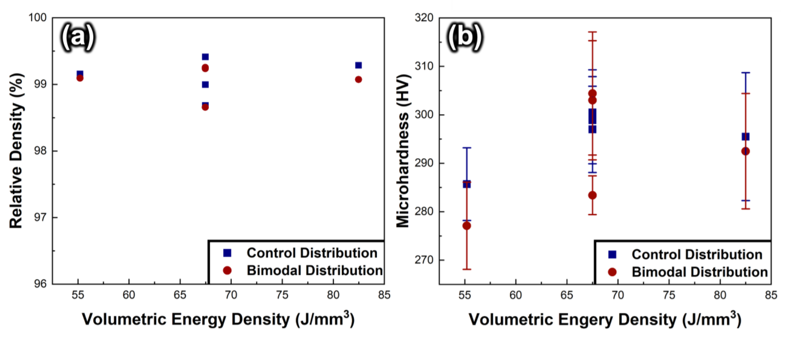
Figure 1 quantifies the cumulative and volume fraction differences between the control and bimodal PSDs. The d10, d50 and d90 are 18.7, 28.5 and 43.6 µm for the control PSD and 14.5, 32.9 and 50.8 µm for the bimodal PSD, respectively. As expected from the volume fraction vs. mesh size plots, the control 718 maintains a smaller average and median diameter and standard deviation than the bimodal PSD. Given the distribution of the control volume fraction, the skewness is calculated to be 0.81. The bimodal distribution relies on a heightened cumulative fraction between 7–17 µm and 35–80 µm in comparison to the control alloy. Archimedes density measurements in Figure 2a showcase ~99% or higher relative densities over a broad range of volumetric energy densities for both the control and bimodal PSDs. The control PSD resulted in 4 of the 5 sample sets having up to 0.2% higher relative densities, but in the highest scanning speed 67.5 J/mm3 sample set, F, the bimodal PSD had a 0.25% higher relative density, although these relative density differences are minor. Figure 2b demonstrates, for the majority of samples, the microhardness values initially increase up to the middle VED and then decrease in the relative sample groups. Three of the five control samples demonstrated slightly higher microhardness values.
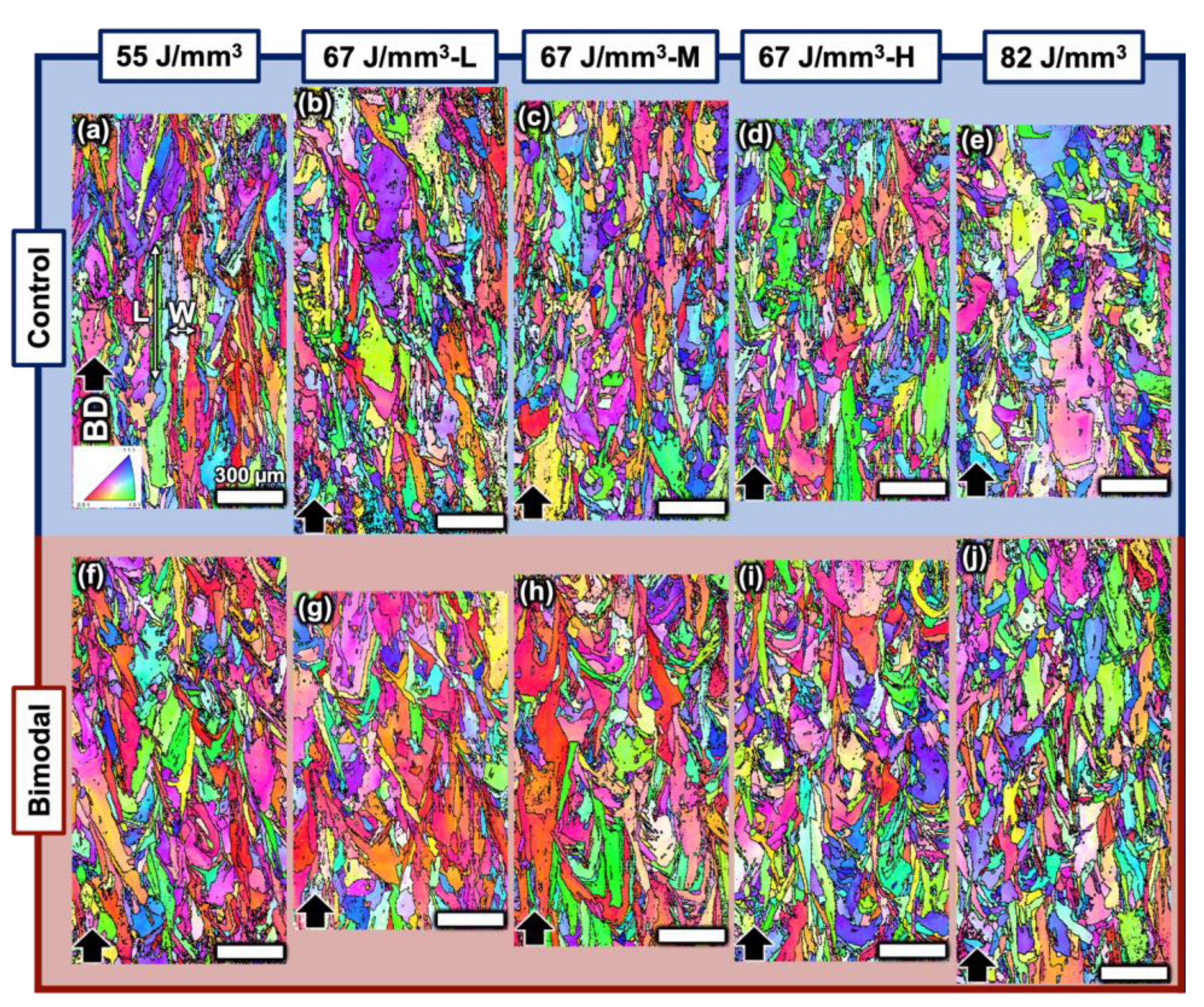
Next, the EBSD technique was utilized to quantify any differences in grain size, morphology and orientation of two sets of samples. Figure 3a–j details the IPFs for each control and bimodal sample in the transverse plane (XY), orthogonal to the build direction Z. Both sets of samples show the typical grain morphology, with large grains spanning across the width of the weld pool and smaller grains near the weld pool boundaries. The IPFs of the ZY plane in Figure 4a–j illuminate the typical columnar grain structure that grows along the build direction due to continued crystal growth via multiple layer to layer remelts. Due to the inherent anisotropic grain structure, the columnar grain width (W) and length (L) were measured separately to accurately capture the microstructure. The W values were nearly identical between the control and bimodal PSDs but the L values for the bimodal samples show a statistically significant increase. The measured average grain sizes from the linear intersection method for the XY and build direction plane (ZY) are detailed in Table 2.
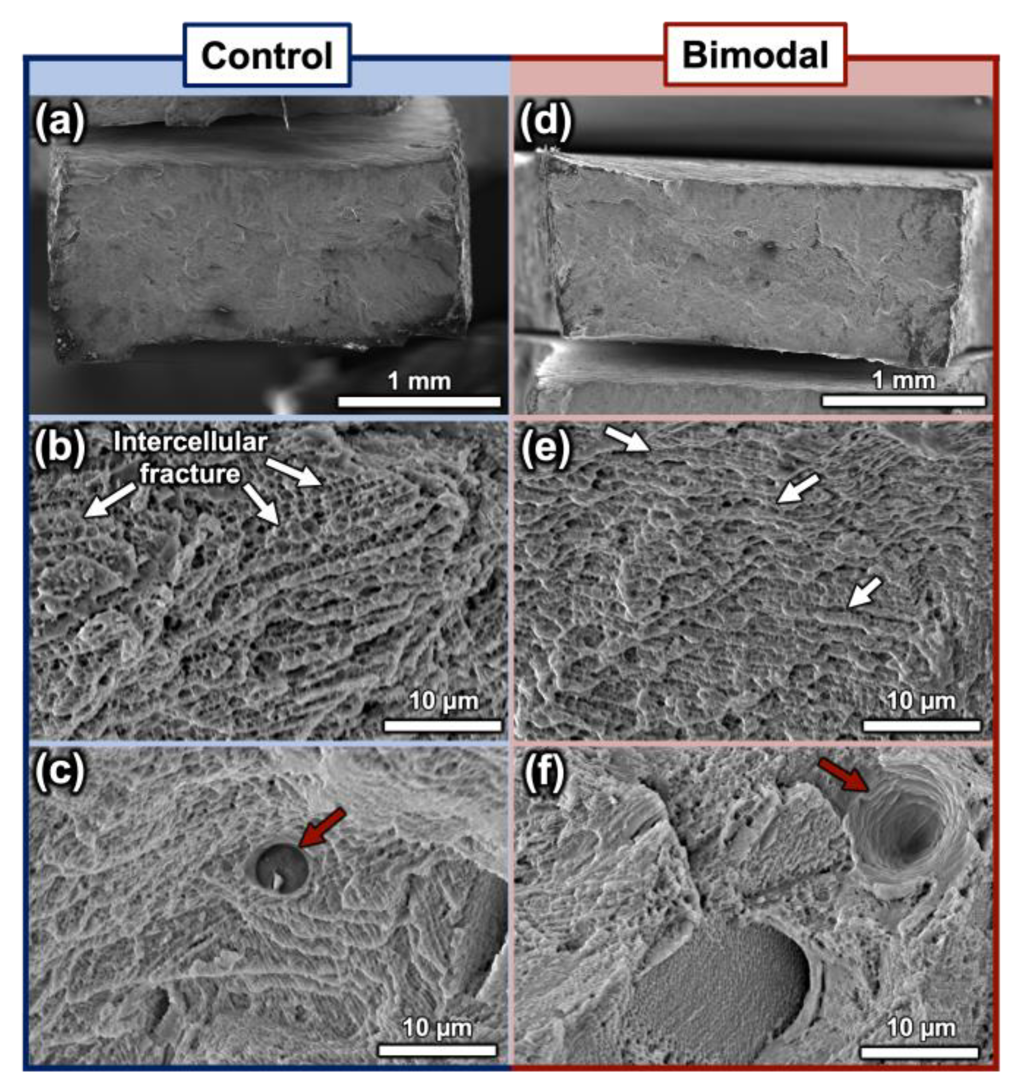
Next, the tensile properties were examined as another validation that the bimodal PSD was a realistic alternative to the typical control PSD. Figure 5a,b reveals that the tensile properties are very similar and the work hardening rate of the bimodal PSD samples was higher than the control samples. The yield strength (YS), ultimate tensile strength (UTS), uniform elongation (εu), elongation to fracture (εf) and work hardening exponent (n) are detailed in Table 3. The average values for each property for the control PSD samples, in addition to n, are slightly (5%) higher than the bimodal PSD sample properties, but are within the standard deviation. The n value of bimodal PSD samples is 10% greater than the control samples. Figure 5c delves deeper into the grain size characteristics of sample C, for both the XY and ZY plane in the control and bimodal states. The curves maintain relatively similar distributions, with the XY planes both having a higher area fraction of smaller grains and the respective global maximum grain sizes being within the ZY planes. Interestingly, the bimodal IPFs contained the highest overall grain sizes of the 4 IPFs, which accounted for 15% of the area fraction. The deformed tensile surfaces were then examined and the primary deformation in both sample types were intercellular fracture and ductile dimples, as observed in Figure 6a–f. Both sets of samples also produced a small but similar fraction of trapped gaseous pores that acted as stress concentration points.

4. Discussion

These microhardness measurements and tensile results confirm that this bimodal PSD samples are statistically similar in the AP state, in comparison to the unimodal control 718, but some differences can be observed. The density measurements and fracture surfaces reveal that there are similar levels of measured porosity, likely caused by gasses dissolved or trapped in the powder feedstock [31,32]. Given these materials were processed with similar parameters and based on our previous work, the fracture surface and tensile results confirm a similar deformation mechanism [28]. The intercellular fracture suggests that the material was processed with near-optimal parameter sets, therefore signifying that the change in PSD does not alter the optimal parameter sets significantly. Because the observed levels of porosity were similar in both sample sets, it was ignored as a major contributor to any differences in mechanical properties. These similar parameters were confirmed to have near-identical mechanical strengths based on the microhardness experiments, with only ~30 HV differences overall parameter sets and three of the five sets showing slightly higher averages for the control PSD. While the largest grains were observed in the ZY plane, the XY plane was used for the microhardness experiments because the size of the microhardness indent was more similar to the smaller grains present on the XY plane, allowing for proper sampling of the grains.
The increased maximum grain size observed in the bimodal PSD samples detailed in Figure 5c is the most substantial microstructure difference between the two sets of samples. This difference can help explain the slight decrease in YS and UTS and the increase in n in the bimodal PSD samples. These prominently larger grains make up ~15% of the area fraction and decrease the YS and UTS for the bimodal samples by lowering the average grain boundary density. This microstructure difference may explain why we see a slight decrease in the microhardness values for three of the five bimodal PSD samples. These larger grains also have a higher capacity for dislocation storage, therefore leading to greater work hardening rate and work hardening exponent [33,34,35,36]. Within these grains are dislocation cellular walls observed in our previous work, which act as soft barriers to dislocation motion. They have a minor effect on the overall n in comparison to hard barriers like precipitates or grain boundaries, but are unique to LPBF materials and, therefore, the added work hardening ability from larger grains becomes more apparent [29,37,38]. The last aspect that can affect the overall deformation behavior and work hardening of the material as it plastically deforms is the grain boundary characteristics. This perspective has gained recent attention within the AM community given the highly tunable nature of the microstructure by varying process parameters to create various LAGB/HAGB ratios [39,40,41,42]. From the EBSD results shown in Figure 3 and Figure 4, LAGB/HAGB ratios were measured and shown in Table 4.
In almost all cases, the bimodal PSD demonstrates either an equivalent or lower LAGB/HAGB ratio. LAGBs have been suggested to be easier barriers for dislocation penetration, leading to minor increases in strength, but allowing higher levels of plasticity [42]. Although the ratio is nearly identical for the tensile samples parameter set (C), in both the XY and ZY planes, the general trend for the bimodal PSD samples over all parameter sets is likely to be more accurate. The heightened levels of HAGBs in the bimodal PSD samples support the higher work hardening exponent of the material because of the associated high energy penalty for dislocation transmission, increasing dislocation pile-ups at grain boundaries. These microstructural arguments are further supported by the similarities of the nature of the work hardening rate between the sample groups, as shown in Figure 5b. The plots simply show work hardening rate differences in magnitude, which suggests that the deformation mechanisms do not change. The elevated fraction of HAGBs in the bimodal PSD samples is interesting and can be directly tied to differences in solidification behavior in comparison to the control PSD [39]. The exact mechanism is difficult to conclude but is likely tied to an expected higher packing factor of the bimodal powder bed prior to solidification. The lower YS and UTS of the bimodal PSD are controlled by the local pockets of larger grains and higher-density areas with LAGB. Therefore, these results show promise in the adaptation of a bimodal PSD for a unimodal PSD.
The PSDs and the nuance differences in their spreadability along the powder bed prior to exposure can help explain the grain size differences. Jacob et al. and Mussatto et al. measured the packing density of a bimodal and wider PSD in comparison to a control sample set and found the deposited 316L stainless steel and 17–42 steel powder achieved higher packing densities [14,16]. The large particles tend to help fill large volumes to full density and work harmoniously with the fine particles that pack in between, resulting in an optimally packed powder bed. With the higher-density powder bed and the same energy input, the overall thermal gradients will decrease, allowing larger grains to form, explaining the increasing upper grain size limit in the bimodal PSD [43,44]. The upper surface contour of the powder layer will also be more consistent after the recoater blade leveling due to the finer particles filling in the grooves. This rationale may help explain the work done by Kuznetsov et al., who also tested a bimodal PSD sample and found it to have a more homogenous microhardness response, likely due to this consistent packing and proceeding melting [17]. Hence, the bimodal PSD approach results in favorable economics and more consistent and homogenous mechanical properties, which are essential for the general adoption of LPBF by establishing narrow mechanical property variation windows.

5. Conclusions

We have compared the microstructures (grain size, morphology, orientation and boundary characteristics) and mechanical properties of the control and bimodal PSD 718 alloys. Although both sample sets have similar microstructures, the bimodal PSD samples have significantly higher upper limits of grain sizes and lower levels of the LAGB/HAGB ratio. Both the larger grains and lower LAGB/HAGB ratios generate slightly lower YS and UTS but higher work hardening rates. This work improves our understanding on how a bimodal PSD can enrich the industry standard unimodal PSD for the LPBF processes. The nature of this study necessitates future works to demonstrate that these principles are repeatable and scalable for larger samples to accurately declare that unimodal and bimodal PSD are comparable as observed in this work. Computational fluid dynamics simulations will be one key component to further investigate the printability differences between samples printed with the two PSDs.

Author Contributions

Conceptualization, B.T.S., J.L., W.J. and X.Z.; methodology, B.T.S.; formal analysis, B.T.S.; investigation, B.T.S.; resources, H.W. and X.Z.; writing—original draft preparation, B.T.S.; writing—review and editing, B.T.S., J.L. and X.Z.; supervision, X.Z.; project administration, W.J., H.W. and X.Z.; funding acquisition, W.J., H.W. and X.Z. All authors have read and agreed to the published version of the manuscript.

Funding

Stegman and Zhang would like to acknowledge the partial financial support from the NSF-DFG grant 2228266. Lopez was supported by an NSF-AGEP Graduate student fellowship.

Data Availability Statement

Not applicable.

Acknowledgments

Stegman and Zhang would like to acknowledge the partial financial support from the NSF-DFG grant 2228266. Lopez was supported by an NSF-AGEP Graduate student fellowship. We would like to acknowledge access to the microscopy center in the School of Materials Engineering at Purdue University.

Conflicts of Interest

William Jarosinski declares his employment by and shareholding in Praxair Surface Technologies, Inc., a Linde company, through company-sponsored savings and retirement plans. Praxair Surface Technologies is a manufacturer of metal powders for additive manufacturing, representing potential conflict of interest.

References

  1. Bourell, D.; Kruth, J.P.; Leu, M.; Levy, G.; Rosen, D.; Beese, A.M.; Clare, A. Materials for additive manufacturing. CIRP Ann. Manuf. Technol. 2017, 66, 659–681. [Google Scholar] [CrossRef]
  2. Moghimian, P.; Poirié, T.; Habibnejad-Korayem, M.; Zavala, J.A.; Kroeger, J.; Marion, F.; Larouche, F. Metal powders in additive manufacturing: A review on reusability and recyclability of common titanium, nickel and aluminum alloys. Addit. Manuf. 2021, 43, 102017. [Google Scholar] [CrossRef]
  3. Mustafa, K.; Mohammad, U. A Review: Chill-Block Melt Spin Technique, Theories & Applications; Bentham Science Publishers: Sharjah, United Arab Emirates, 2013; Volume 5, p. 134. [Google Scholar]
  4. Neikov, O.D.; Naboychenko, S. Handbook of Non-Ferrous Metal Powders: Technologies and Applications; Elsevier: Amsterdam, The Netherlands, 2009; p. 114. [Google Scholar]
  5. Richter, J.; Torrent, C.J.J.; Krochmal, M.; Wegener, T.; Vollmer, M.; Niendorf, T. A comparative study using water atomized and gas atomized powder in laser powder bed fusion—Assessment of the fatigue performance. Int. J. Fatigue 2023, 168, 107468. [Google Scholar] [CrossRef]
  6. Sehhat, M.H.; Sutton, A.T.; Hung, C.-H.; Newkirk, J.W.; Leu, M.C. Investigation of Mechanical Properties of Parts Fabricated with Gas- and Water-Atomized 304L Stainless Steel Powder in the Laser Powder Bed Fusion Process. JOM 2022, 74, 1088–1095. [Google Scholar] [CrossRef]
  7. Anderson, I.E.; White, E.M.; Dehoff, R. Feedstock powder processing research needs for additive manufacturing development. Curr. Opin. Solid State Mater. Sci. 2018, 22, 8–15. [Google Scholar] [CrossRef]
  8. Wang, L.; Tan, Z.; Wang, S.; Liu, W.; Hao, J.; Zhang, X.; Deng, S.; Yu, C.; Zheng, H.; Zeng, Z.; et al. Atomization gases dependent mechanical properties in the laser powder bed fusion manufactured 304L stainless steel. J. Mater. Process. Technol. 2023, 316, 117966. [Google Scholar] [CrossRef]
  9. Shi, Y.; Lu, W.; Sun, W.; Zhang, S.; Yang, B.; Wang, J. Impact of gas pressure on particle feature in Fe-based amorphous alloy powders via gas atomization: Simulation and experiment. J. Mater. Sci. Technol. 2022, 105, 203–213. [Google Scholar] [CrossRef]
  10. Ruan, G.; Liu, C.; Qu, H.; Guo, C.; Li, G.; Li, X.; Zhu, Q. A comparative study on laser powder bed fusion of IN718 powders produced by gas atomization and plasma rotating electrode process. Mater. Sci. Eng. A 2022, 850, 143589. [Google Scholar] [CrossRef]
  11. Lefebvre, L.; Whiting, J.; Nijikovsky, B.; Brika, S.; Fayazfar, H.; Lyckfeldt, O. Assessing the robustness of powder rheology and permeability measurements. Addit. Manuf. 2020, 35, 101203. [Google Scholar] [CrossRef]
  12. Zegzulka, J.; Gelnar, D.; Jezerska, L.; Prokes, R.; Rozbroj, J. Characterization and flowability methods for metal powders. Sci. Rep. 2020, 10, 21004. [Google Scholar] [CrossRef]
  13. Brika, S.E.; Letenneur, M.; Dion, C.A.; Brailovski, V. Influence of particle morphology and size distribution on the powder flowability and laser powder bed fusion manufacturability of Ti-6Al-4V alloy. Addit. Manuf. 2020, 31, 100929. [Google Scholar] [CrossRef]
  14. Mussatto, A.; Groarke, R.; O’neill, A.; Obeidi, M.A.; Delaure, Y.; Brabazon, D. Influences of powder morphology and spreading parameters on the powder bed topography uniformity in powder bed fusion metal additive manufacturing. Addit. Manuf. 2021, 38, 101807. [Google Scholar] [CrossRef]
  15. Farzadfar, S.A.; Murtagh, M.J.; Venugopal, N. Impact of IN718 bimodal powder size distribution on the performance and productivity of laser powder bed fusion additive manufacturing process. Powder Technol. 2020, 375, 60–80. [Google Scholar] [CrossRef]
  16. Jacob, G.; Brown, C.U.; Donmez, A. The Influence of Spreading Metal Powders with Different Particle Size Distributions on the Powder Bed Density in Laser-Based Powder Bed Fusion Processes; US Department of Commerce, National Institute of Standards and Technology: Gaithersburg, MD, USA, 2018. Available online: https://www.nist.gov/publications/influence-spreading-metal-powders-different-particle-size-distributions-powder-bed (accessed on 18 June 2023).
  17. A Kuznetsov, P.; Shakirov, I.V.; Zukov, A.S.; Bobyr’, V.V.; Starytsin, M.V. Effect of particle size distribution on the structure and mechanical properties in the process of laser powder bed fusion. J. Physics Conf. Ser. 2021, 1758, 012021. [Google Scholar] [CrossRef]
  18. Martin, J.H.; Barnes, J.E.; Rogers, K.A.; Hundley, J.; LaPlant, D.L.; Ghanbari, S.; Tsai, J.-T.; Bahr, D.F. Additive manufacturing of a high-performance aluminum alloy from cold mechanically derived non-spherical powder. Commun. Mater. 2023, 4, 39. [Google Scholar] [CrossRef]
  19. James, W.B.; Samal, P.; Newkirk, J.; Adams, J.P.; Hamill, J.J.A.; Schade, C.; Dunkley, J.J.; Pittenger, B.; Luk, S.H.; Iacocca, R.G.; et al. Powder Metallurgy Methods and Applications. ASM Int. 2015, 7, 9–19. [Google Scholar] [CrossRef]
  20. Wohlers, T. State of the industry report–Executive summary. Proc. Rapid Prototyp. Manuf. 1998, 98, 1–204. [Google Scholar]
  21. Wohlers, T.; Tim, C. Wohlers report 2010. Addit. Manuf. State Ind. Annu. Worldw. Prog. Rep 2010, 1–250. [Google Scholar]
  22. Ding, J.; Xue, S.; Shang, Z.; Li, J.; Zhang, Y.; Su, R.; Niu, T.; Wang, H.; Zhang, X. Characterization of precipitation in gradient Inconel 718 superalloy. Mater. Sci. Eng. A 2021, 804, 140718. [Google Scholar] [CrossRef]
  23. Ding, J.; Zhang, Y.; Niu, T.; Shang, Z.; Xue, S.; Yang, B.; Li, J.; Wang, H.; Zhang, X. Thermal Stability of Nanocrystalline Gradient Inconel 718 Alloy. Crystals 2021, 11, 53. [Google Scholar] [CrossRef]
  24. Schafrik, R.; Ward, D.; Groh, J. Application of Alloy 718 in GE Aircraft Engines: Past, Present and Next Five Years. Proc. Int. Symp. Superalloys Var. Deriv. 2001, 718, 1–11. [Google Scholar] [CrossRef]
  25. Special Metals Corporation, Special Metals-Inconel Alloy 718. Tech. Bull. 2007, pp. 1–28. Available online: https://www.specialmetals.com/documents/technical-bulletins/inconel/inconel-alloy-718.pdf (accessed on 25 June 2023).
  26. Zhang, D.; Niu, W.; Cao, X.; Liu, Z. Effect of standard heat treatment on the microstructure and mechanical properties of selective laser melting manufactured Inconel 718 superalloy. Mater. Sci. Eng. A 2015, 644, 32–40. [Google Scholar] [CrossRef]
  27. Sanchez, S.; Smith, P.; Xu, Z.; Gaspard, G.; Hyde, C.J.; Wits, W.W.; Ashcroft, I.A.; Chen, H.; Clare, A.T. Powder Bed Fusion of nickel-based superalloys: A review. Int. J. Mach. Tools Manuf. 2021, 165, 103729. [Google Scholar] [CrossRef]
  28. Catchpole-Smith, S.; Aboulkhair, N.; Parry, L.; Tuck, C.; Ashcroft, I.; Clare, A. Fractal scan strategies for selective laser melting of ‘unweldable’ nickel superalloys. Addit. Manuf. 2017, 15, 113–122. [Google Scholar] [CrossRef]
  29. Stegman, B.; Shang, A.; Hoppenrath, L.; Raj, A.; Abdel-Khalik, H.; Sutherland, J.; Schick, D.; Morgan, V.; Jackson, K.; Zhang, X. Volumetric energy density impact on mechanical properties of additively manufactured 718 Ni alloy. Mater. Sci. Eng. A 2022, 854, 143699. [Google Scholar] [CrossRef]
  30. Stegman, B.; Yang, B.; Shang, Z.; Ding, J.; Sun, T.; Lopze, J.; Jarosinski, W.; Wang, H. Zhang, Reactive introduction of oxide nanoparticles in additively manufactured 718 Ni alloys with improved high temperature performance. J. Alloys Compd. 2022, 404–406, 1. [Google Scholar] [CrossRef]
  31. Wu, Z.; Basu, D.; Meyer, J.L.L.; Larson, E.; Kuo, R.; Beuth, J.; Rollett, A. Study of Powder Gas Entrapment and Its Effects on Porosity in 17-4 PH Stainless Steel Parts Fabricated in Laser Powder Bed Fusion. JOM 2021, 73, 177–188. [Google Scholar] [CrossRef]
  32. Gordon, J.V.; Narra, S.P.; Cunningham, R.W.; Liu, H.; Chen, H.; Suter, R.M.; Beuth, J.L.; Rollett, A.D. Defect structure process maps for laser powder bed fusion additive manufacturing. Addit. Manuf. 2020, 36, 101552. [Google Scholar] [CrossRef]
  33. Rudloff, M.; Risbet, M.; Keller, C.; Hug, E. Influence of the size effect on work hardening behaviour in stage II of Ni20wt.%Cr. Mater. Lett. 2008, 62, 3591–3593. [Google Scholar] [CrossRef]
  34. del Valle, J.; Carreño, F.; Ruano, O. Influence of texture and grain size on work hardening and ductility in magnesium-based alloys processed by ECAP and rolling. Acta Mater. 2006, 54, 4247–4259. [Google Scholar] [CrossRef]
  35. Sinclair, C.; Poole, W.; Bréchet, Y. A model for the grain size dependent work hardening of copper. Scr. Mater. 2006, 55, 739–742. [Google Scholar] [CrossRef]
  36. Guo, L.; Chen, Z.; Gao, L. Effects of grain size, texture and twinning on mechanical properties and work-hardening behavior of AZ31 magnesium alloys. Mater. Sci. Eng. A 2011, 528, 8537–8545. [Google Scholar] [CrossRef]
  37. Wang, X.; Zheng, B.; Yu, K.; Jiang, S.; Lavernia, E.J.; Schoenung, J.M. The role of cell boundary orientation on mechanical behavior: A site-specific micro-pillar characterization study. Addit. Manuf. 2021, 46, 102154. [Google Scholar] [CrossRef]
  38. Riabov, D.; Leicht, A.; Ahlström, J.; Hryha, E. Investigation of the strengthening mechanism in 316L stainless steel produced with laser powder bed fusion. Mater. Sci. Eng. A 2021, 822, 141699. [Google Scholar] [CrossRef]
  39. Lyu, F.; Hu, K.; Wang, L.; Gao, Z.; Zhan, X. Regionalization of microstructure characteristics and mechanisms of slip transmission in oriented grains deposited by wire arc additive manufacturing. Mater. Sci. Eng. A 2022, 850, 45–60. [Google Scholar] [CrossRef]
  40. Abdi, F.; Eftekharian, A.; Huang, D.; Rebak, R.B.; Rahmane, M.; Sundararaghavan, V.; Kanyuck, A.; Gupta, S.K.; Arul, S.; Jain, V.; et al. Grain boundary engineering of new additive manufactured polycrystalline alloys. Forces Mech. 2021, 4, 100033. [Google Scholar] [CrossRef]
  41. Fang, X.; Li, H.; Wang, M.; Li, C.; Guo, Y. Characterization of texture and grain boundary character distributions of selective laser melted Inconel 625 alloy. Mater. Charact. 2018, 143, 182–190. [Google Scholar] [CrossRef]
  42. Wei, F.; Cheng, B.; Kumar, P.; Wang, P.; Lee, J.J.; Seng, H.L.; Cheong, A.; Lau, K.B.; Tan, C.C. A comparative study of additive manufactured and wrought SS316L: Pre-existing dislocations and grain boundary characteristics. Mater. Sci. Eng. A 2022, 833, 142546. [Google Scholar] [CrossRef]
  43. Raghavan, N.; Simunovic, S.; Dehoff, R.; Plotkowski, A.; Turner, J.; Kirka, M.; Babu, S. Localized melt-scan strategy for site specific control of grain size and primary dendrite arm spacing in electron beam additive manufacturing. Acta Mater. 2017, 140, 375–387. [Google Scholar] [CrossRef]
  44. Gockel, J.; Sheridan, L.; Narra, S.P.; Klingbeil, N.W.; Beuth, J. Trends in Solidification Grain Size and Morphology for Additive Manufacturing of Ti-6Al-4V. JOM 2017, 69, 2706–2710. [Google Scholar] [CrossRef]
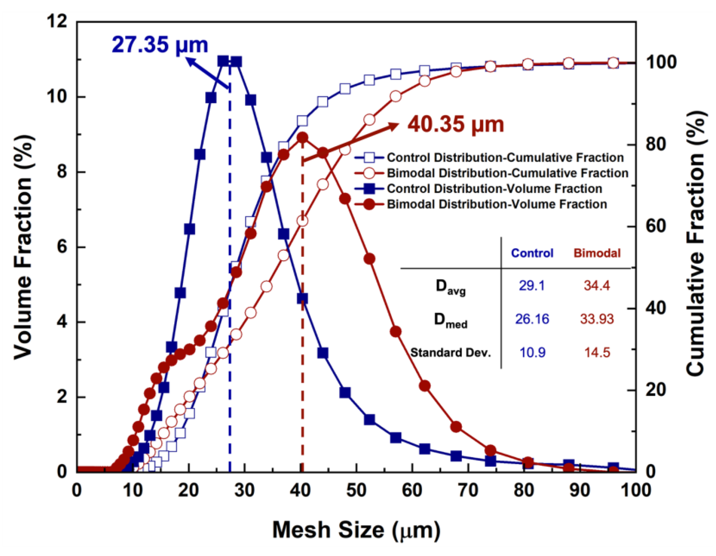
Figure 1. Cumulative and volume fractions of the control and bimodal PSDs, highlighting the unimodal control PSDs and the bimodal powder size distribution. Descriptive weighted statistics including average and median diameter and standard deviation are listed in the incorporated table.
Metals 13 01384 g001
Figure 2. (a) Relative density plotted against volumetric energy density (VED) for both the control and bimodal PSDs. (b) Microhardness values of the XY plane plotted against VED for both the control and bimodal PSDs.
Metals 13 01384 g002
Figure 3. Electron backscatter diffraction (EBSD) inverse pole figures (IPF) of the XY planes of the (ae) control distribution and (fj) bimodal distribution with the fine grains of the weld pool boundaries marked by the white dashed lines; 67 J/mm3 -L/M/H corresponds to the low, medium and high laser scanning speed of the samples with the same VED.
Metals 13 01384 g003
Figure 4. IPF maps of the ZY planes of the (ae) control PSD and (fj) bimodal PSD samples with the average columnar grain widths and length remaining within the standard deviation between the control and bimodal sample sets; 67 J/mm3 -L/M/H corresponds to the low, medium and high laser scanning speed of the samples with the same VED.
Metals 13 01384 g004
Figure 5. (a) True stress–strain curves for the control and bimodal distribution samples showing similar mechanical responses. (b) Characteristic true stress–strain curves with the corresponding overlayed work hardening rate curves highlighting the slightly higher work hardening rate in the bimodal samples. (c) Grain diameter distribution generated from the OIM EBSD software, measuring parameter set C for the XY and ZY planes in both the control and bimodal distributions.
Metals 13 01384 g005
Figure 6. SEM secondary electron (SE) micrographs of various magnifications of the fracture surfaces of the (ac) control distribution and (df) bimodal distribution samples showing small trapped gaseous porosity, lineated patterns denoting intercellular fracture and ductile dimples.
Metals 13 01384 g006
Table 1. Laser powder bed fusion (LPBF) parameters and microhardness values with corresponding sample IDs used for both the control and bimodal powder size distributions (PSDs). All samples were printed with a layer thickness and hatch spacing of 40 and 110 µm.
Sample IDEnergy Density (J/mm3)Laser Power (W)Scan Speed (mm/s)Control PSD Microhardness (HV)Bimodal PSD Microhardness (HV)
A55.2256.51056286 ± 8277 ± 9
B67.5256.5864299 ± 9303 ± 12
C67.5285960297 ± 9283 ± 4
D67.5313.51056301 ± 9304 ± 13
E82.5313.5864296 ± 13292 ± 12
Table 2. Averaged grain size in the XY plane and the columnar grain width (W) and length (L) in the ZY plane of the control and bimodal samples.
Sample IDControl PSD-XY (µm)Bimodal PSD-XY (µm)Control PSD-ZY-W (µm)Bimodal PSD-ZY-W (µm)Control PSD-ZY-L (µm)Bimodal PSD-ZY-L (µm)
A47 ± 1639 ± 655 ± 673 ± 5139 ± 3148 ± 2
B35 ± 540 ± 861 ± 655 ± 4119 ± 40137± 3
C40 ± 1238 ± 751 ± 973 ± 8131 ± 6160 ± 3
D43 ± 1238 ± 756 ± 761 ± 1126 ± 4131 ± 1
E51 ± 1341 ± 463 ± 660 ± 10126 ± 3130 ± 5
Table 3. Average mechanical properties from the control and bimodal samples. Note: n—work hardening exponent.
Sample TypeYield Strength (MPa)Ultimate Tensile Strength (MPa)Uniform Elongation (%)Elongation to Fracture (%)n
Control 414 ± 22746 ± 8829 ± 241 ± 50.242 ± 0.022
Bimodal 399 ± 41708 ± 5128 ± 238 ± 0.40.261 ± 0.007
Table 4. Measured LAGB/HAGB ratios for both the control and bimodal PSD samples in each parameter set and in both the XY and ZY planes.
Sample IDControl XY LAGB/HAGB Ratio (mm/mm)Bimodal XY LAGB/HAGB Ratio (mm/mm)Control ZY LAGB/HAGB Ratio (mm/mm)Bimodal ZY LAGB/HAGB Ratio (mm/mm)
A0.240.230.380.22
B0.220.190.330.24
C0.240.230.250.28
D0.170.210.260.24
E0.230.130.280.30
Disclaimer/Publisher’s Note: The statements, opinions and data contained in all publications are solely those of the individual author(s) and contributor(s) and not of MDPI and/or the editor(s). MDPI and/or the editor(s) disclaim responsibility for any injury to people or property resulting from any ideas, methods, instructions or products referred to in the content.