Review

Review of Particle-Based Computational Methods and Their Application in the Computational Modelling of Welding, Casting and Additive Manufacturing

1
Mechanical Engineering, College of Science and Engineering, University of Galway, H91HX31 Galway, Ireland
2
I-Form Advanced Manufacturing Research Centre, Ireland
3
Ryan Institute for Environmental, Marine and Energy Research, University of Galway, H91 TK33 Galway, Ireland
Metals 2023, 13(8), 1392; https://doi.org/10.3390/met13081392
Submission received: 23 June 2023 / Revised: 14 July 2023 / Accepted: 17 July 2023 / Published: 3 August 2023
(This article belongs to the Special Issue Modeling of Alloy Solidification)

Abstract

:
A variety of particle-based methods have been developed for the purpose of computationally modelling processes that involve, for example, complex topological changes of interfaces, significant plastic deformation of materials, fluid flow in conjunction with heat transfer and phase transformation, flow in porous media, granular flow, etc. Being different from the conventional methods that directly solve related governing equations using a computational grid, the particle-based methods firstly discretize the continuous medium into discrete pseudo-particles in mathematics. The methods then mathematically solve the governing equations by considering the local interaction between neighbouring pseudo-particles. Such solutions can reflect the overall flow, deformation, heat transfer and phase transformation processes of the target materials at the mesoscale and macroscale. This paper reviews the fundamental concepts of four different particle-based methods (lattice Boltzmann method—LBM, smoothed particle hydrodynamics—SPH, discrete element method—DEM and particle finite element method—PFEM) and their application in computational modelling research on welding, casting and additive manufacturing.

1. Introduction

In the research field of simulation-based engineering science, there are three categories of computational modelling methods, in terms of how to implement spatial discretisation. They include the Eulerian method, the Lagrangian method and the hybrid method [1]. In the Eulerian method, the computational grid does not move with the fluid flow or material deformation, while there is advection of mass between the target material and the computational grid. In the Lagrangian method, however, the computational grid moves with the flowing/deforming target material. The hybrid method uses some techniques to combine the Largangian approach with the Eulerian approach. The successful employment of an arbitrary Lagrangian–Eulerian (ALE) method in the finite element (FE) analysis software ABAQUS is a good example of the application of hybrid methods in computational modelling. The ALE adaptive meshing makes the FE computational grid “move independently of the target material”, to “maintain a high-quality mesh throughout an analysis” [2]. Regardless of what method is used to implement the spatial discretisation, the target material is assumed to be either continuous (e.g., single material/phase problems) or piecewise continuous (e.g., multi-material or multiphase problems) in the computational modelling of continuum mechanics problems. For example, in the FE modelling of solid mechanics problems, the partial differential constitutive equation of a linear elastic problem can be formulated as [3]
( λ + μ ) x i ( u k x k ) + μ 2 u i = 0
where λ and μ are the Lamé coefficients, u is material displacement and x is a dimension in a Cartesian coordinate system. Such a constitutive equation, in conjunction with related boundary conditions and material properties, is solved on an FE grid, to computationally solve a boundary-value problem of linear elastic solid mechanics problem. Regarding the computational fluid dynamics (CFD) modelling of single-phase incompressible Newtonian fluid flow and heat transfer problems using the finite volume method [4], it is typical that the Navier–Stokes equations are solved on an Eulerian or Lagrangian finite volume grid. Regarding the level set method for multiphase problems, the propagation/variation of the inter-phase interface is implicitly captured by solving the below level set equation on a computationally grid [5]:
φ t + V · φ = 0
where φ is the level set function, V is the fluid velocity vector and t is time. In the afore three examples, regardless of whether the target material is uniform (such as in the FE analysis of isotropic linear elastic materials and the CFD modelling of single-phase materials) or non-uniform (e.g., in the level set modelling of multiphase problems), the target material is always assumed to be continuous or piecewise continuous.
The benefit of treating the target material as a mathematically continuous (or piecewise continuous) medium in the computational modelling is very obvious. Firstly, it directly reflects the fundamental concept of continuum mechanics, which study the macroscopic behaviour of materials by using a continuous outlook (i.e., treating the target material as a continuous mass) [6]. Secondly, related computational modelling is normally computationally efficient. In the continuum mechanics, the particulate nature of target materials (such as material microstructure, defects, inter-atomic interactions, etc.) are not explicitly considered. The influence of such particulate nature (or properties) of the target material is normally implicitly and indirectly taken into account in the continuum mechanics by employing related macroscopic properties of the target material (such as elasticity and plasticity of solid materials, the viscosity and density of fluids, etc.) in the continuum mechanics. Related computational methods are applicable to the modelling of an appreciable volume of material (e.g., up to the volume of an entire engineering component) during a process of appreciable length (e.g., comparable to an entire engineering process).
All engineering materials consist of discrete entities (such as atoms, molecules, grains, defects, etc.). When a “discrete outlook” concept is employed, it regards the target material as a population of individual material points (or particles) that interacts with one another at very short distances [6]. Such a particulate approach studies the properties of the particulates and the interaction between the particulates. The particulates can be, as examples, atoms, molecules or any other microscopic particulates. Such an approach relates to discrete mechanics [7]. Regarding the computational modelling of materials using the concept of discrete mechanics, molecular dynamics (MD) is a good example. In MD, the target material is assumed to consist of a population of individual but interacting atoms [8]. The interaction can be mathematically formulated by using a potential function. MD implements classical mechanics to study the classical motion of many-body systems. It has been successfully employed to computationally predict, for example, the solidification of metals at the nanoscale [9], the welding of thermosetting polymers [10], the roll casting of Cu/Al clad plates [11] and extensive additive manufacturing [12]. In Figure 1, which shows the MD modelling results of the solidification process of pure aluminium, each grey, green or red dot represents an individual aluminium atom. There are 1,000,188 individual and interacting aluminium atoms included in the simulation domain.
On the one hand, the modelling methods using the particulate approach can directly reflect the microscopic processes and phenomena of materials (e.g., the motion and interactions of atoms of the target material). On the other hand, such a modelling method is very computationally costly and is normally only applicable to a very small volume of material. For example, as was reviewed in [13], there are normally a limited number of atoms in an MD simulation domain and the time window is typically on the order of magnitude of hundreds of picoseconds. It is often applied regarding the finite-size effects of such an incredibly small simulation domain (on the nanoscale) [14]. Due to such a limited length of time that can be considered in MD simulations, normally only very extreme levels of cooling rate (e.g., on the order of 105 K/s [14]) can be employed in the modelling of a material during cooling.
It is clear that the modelling methods based on the “continuous outlook” concept suit applications in a large volume of material that can provide the macroscopic properties of the target material or process. The modelling methods based on the “discrete outlook” concept suit applications where the particular delicate interaction between particulates of the material is the main interest of research. In the application of computational modelling in science and engineering, there is a type of scenario where some delicate processes of a macroscopic system need to be computationally formulated and predicted. One good example of such a scenario is predicting the flow of fluid in porous media. If one only cares about the overall macroscopic properties of the flow, such as the overall static pressure loss of fluid across the porous media, one can very easily use the common Darcy’s law (or its variants) in a conventional CFD modelling based on the finite volume method [15] to get the job done. Darcy’s law assumes the porous media is a continuous uniform permeable material, i.e., a “continuous outlook”. Rather than considering the individual pores, Darcy’s law uses a loss coefficient to characterise the macroscopic properties of the porous media regarding the fluid pressure loss. However, if one cares about the pore-scale characteristics of a complex flow problem (such as multiphase flow in heterogeneous porous media) [16,17], special care must be taken. For example, if the modelling needs to be applied to the flow problem in an appreciable volume of porous media, the “discrete outlook” that considers the actual atoms is not applicable because its computational cost is unaffordable. Some other good examples of such special scenario include high speed impact [18], immiscible multiphase flow [19], fluid–structure interaction [20] and flow/heat transfer involving moving boundaries [21]. All these problems in this special scenario either have complex (or moving) interfaces or involve significant and complex (as well as delicate) interface topological changes.
The particle-based computational modelling methods particularly suit this special scenario. As was addressed by Raabe in a comprehensive review [22], the pseudo-particle method is a group of coarse-grained computational modelling methods that work on a scale bigger than the atomic-scale. The pseudo-particle is a concept of mesoscopic material element, which has position, mass, energy and momentum. The pseudo-particle methods neither directly formulate the inter-atomic or inter-molecular interaction of microscopic problems nor directly solve differential continuum equations (such as the Navier–Stokes equation) using a conventional computational grid. Depending on whether the pseudo-particles move on a fixed grid or continuously in space, there are lattice-based pseudo-particle methods and off-lattice approaches. The pseudo-particles normally represent a material element, which can be either gas, liquid or solid phase. There are two key words that need highlighting regarding the concept of pseudo-particle methods. Firstly, the key word “particle” refers to mesoscopic elements of a material. Each material element represents a very large cluster of atoms (or molecules) rather than individual atoms, molecules or other physical particles/droplets of materials. Secondly, the pseudo-particle modelling methods are still macroscopic models that use the “continuous outlook” concept. They do not explicitly consider the interaction between atoms or molecules. Although they consider the interactions between the mesoscopic material elements (i.e., the pseudo-particles), they are still based on related macroscopic constitutive laws of the target materials. Therefore, the pseudo-particle modelling methods have much better computational efficiency compared with, e.g., the MD modelling.
In this paper, for the convenience of presentation, particle-based computational modelling refers to computational modelling using the pseudo-particle methods. Four different particle-based computational modelling methods are reviewed in the paper: the Lattice Boltzmann Method, the Smoothed Particle Hydrodynamics method, the Discrete Element Method and the Particle Finite Element Method.

2. Lattice Boltzmann Method

Lattice Boltzmann method (LBM) is a type of lattice-based pseudo-particle method. It combines the concept of material pseudo-particles (which was firstly used in the Lattice Gas Automata method) with the kinetic equations of related processes (i.e., the Boltzmann Equation) [23]. When the LBM is employed to formulate the fluid dynamics problems, it satisfies the Navier–Stokes equation on one hand, but does not explicitly solve the Navier–Stokes equation on the other hand. In the LBM, the interaction between material elements is reflected in the concept of collisions of pseudo-particles, which is mathematically formulated by using the kinetics of the probability distribution function (i.e., the Boltzmann Equation):
f t + ξ · f + F · ξ f = Ω ( f )
where f is the probability distribution function, ξ is the microscopic velocity in a direction, t is time and F is the external body force. Ω formulates the collisions between pseudo-particles, which are affected by how the material elements interact with one another as well as the material properties. For example, for fluid dynamics problem, Ω relates to the viscosity, speed of sound, temperature, density and molar mass of the target fluids.
By using the BGK model in conjunction with the single relaxation time approach, the discretized Boltzman equation can be formulated as [24]
f i ( x + e i Δ t , t + Δ t ) = f i ( x , t ) 1 τ [ f i ( x , t ) f i e q ( x , t ) ] + F i ( x , t )
Ω ( f ) = 1 τ [ f i ( x , t ) f i e q ( x , t ) ]
where e i is the velocity in the i direction of the computational grid, τ is the dimensionless relaxation time and f i ( x , t ) e q is the Maxwell–Boltzmann equilibrium probability distribution function, which only depends on the material properties. F i ( x , t ) accounts for the body force as well as the forces due to the interactions between material elements. The probability distribution function can be used to derive the macroscopic properties (such as density and momentum density) of the target material for single-phase or multiphase problems:
ρ ( x , t ) = i f i ( x , t )
ρ ( x , t ) u ( x , t ) = i e i ( x , t ) f i ( x , t )
where u is the actual macroscopic velocity of a material element and e i is the discrete probable velocity of the material element in the probable direction i.
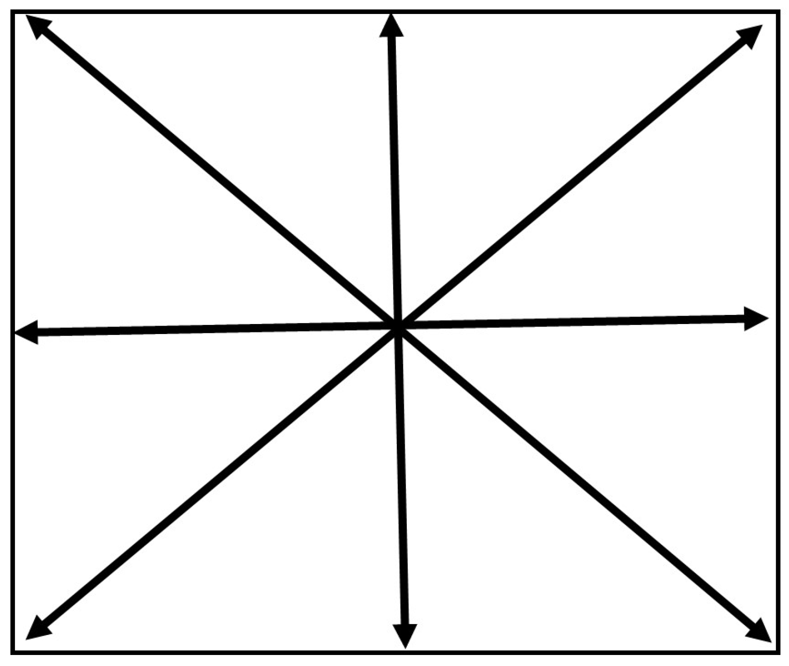
The LBM is normally implemented based on a structured computational grid. For either single-phase problems or multiphase problems, normally the computational grid is static and does not move/deform with fluid flow or solid deformation. It is the temporal and spatial variation in the probability distribution function that reflects the processes of, for example, fluid flow and solid deformation. Therefore, the LBM is normally a type of Eulerian method. The type of LBM computational grid is normally categorised by using codes such as DxQy, where x represents the number of dimensions and y represents the number of directions in which the information of a pseudo-particle can propagate. For example, Figure 2 displays the D2Q9 computational grid that is widely employed in 2D LBM modelling. There are many different types of computational grids that can be employed in LBM modelling. The choice of computational grid depends on information such as the number of dimensions of the target problem, the expected level of accuracy, the affordable computational cost, etc. It is worth noting that different weighting coefficients may apply to different directions in an LBM computational grid. When solving the Boltzmann equation, there are two steps: the Collision Step and the Streaming Step. The Collision Step corresponds to the process of the particle of interest colliding with the neighbouring particles, which reflects the relaxation of probability distribution function f towards the local equilibrium. The Streaming Step reflects the process of information propagation from the particle of interest towards the particles nearby. Related details of the mathematical background of the LBM method can be seen in [23].
When the probability distribution function f only represents the likelihood of a material element having a particular velocity in a particular direction at a particular location, the corresponding LBM can be employed in the CFD modelling of fluid flow problems [22,25]. When the probability distribution functions can characterise not only velocity but also temperature (or thermal energy) of the fluid at the nodes of the computational grid, the corresponding LBM can be employed in the modelling of fluid flow in conjunction with heat transfer. For example, in the LBM modelling performed by Semma et al. [26], a double distribution function method was used, which used one probability distribution function to formulate the flow problems and a different probability distribution function to separately formulate the heat transfer problems. If a third probability distribution function of the material solute concentration can be considered in the LBM [27], the process of fluid flow in conjunction with heat transfer and solute transport can be simulated.

2.1. LBM and Enthalpy Method

Regarding the phase transformation between the liquid and solid phases during solidification or remelting, a particular model of phase transformation is needed to formulate this, as the LBM itself is incapable. An approach similar to the enthalpy formulation of phase transformation was employed by Semma et al. [26] in the computational modelling for melting/solidification problems of pure gallium in a square cavity under the influence of natural convection, which was supported by related verification and validation. In the Enthalpy Method of phase transformation, the evolution of material enthalpy follows the below partial differential equation [28]:
H t + · ( C p T u ) = · ( k T )
where H is enthalpy, T is temperature, u is fluid macroscopic velocity, k is thermal conductivity and C p is specific heat capacity. The enthalpy can be calculated as the sum of the sensible enthalpy and latent heat of fusion. The volume fraction of liquid phase is assumed to be a linear function between the enthalpy of the material at the liquidus temperature and the enthalpy at the solidus temperature. The energy equation is not explicitly solved in the LBM modelling. Again, a collision-streaming approach is used to update the probability distribution function in relation to enthalpy:
g i ( x + e i Δ t , t + Δ t ) = g i ( x , t ) 1 τ [ g i ( x , t ) g i ( x , t ) e q ]
where g i is the probability distribution density of enthalpy in the i direction of the computational grid, g i ( x , t ) e q is the Maxwell–Boltzmann equilibrium probability distribution function relating to the enthalpy and H ( x , t ) = i g i ( x , t ) . Depending on the specific assumptions of the problems, either single relaxation time scheme or multiple relaxation time scheme can be employed in the solution processes.

2.2. LBM and Cellular Automata Method

The LBM model employing the enthalpy formulation mainly computationally formulates the process of phase transformation in the perspective of change of enthalpy of the target materials. If the specific mechanisms and mathematical formulas of solute partition in conjunction with solute diffusion/convection are well understood, the process of phase transformation (solidification or remelting) can be assumed to be driven by the difference between the local interface equilibrium composition and the local actual liquid composition of material—if the liquid phase and solid phase can be assumed to be locally in equilibrium at the interface. For example, in the modelling of the dendritic growth process during natural and forced convection [27,29], it was assumed that the interface equilibrium composition of the liquid phase was
C l * = C 0 + { T l * T l e q + Γ K [ 1 15 ε c o s 4 ( θ θ 0 ) ] } / m
where T l * is the interface temperature, T l e q is the equilibrium liquidus temperature at the initial composition C 0 , C l * is the interface equilibrium solute concentration of the liquid phase, ε is the degree of anisotropy of the surface tension, m is he liquidus slope of the phase diagram, Γ is the Gibbs–Thomson coefficient, K is the curvature of the solid–liquid interface, θ is the growth angle between the normal to the interface and a reference direction and θ 0 is the angle of the preferential growth direction with respect to the reference direction.
The change in solid fraction of the target material can be formulated as a function of the interface equilibrium composition of the liquid phase and the actual composition of the liquid phase:
Δ ϕ s = C l * C l C l * ( 1 k )
where k is the solute partition coefficient k = C s / C l , C s and C l are the solute concentration in the solid phase and liquid phase and ϕ s is the solid fraction. The release of solute into the liquid phase and the release of latent heat can be formulated as
Δ C l = Δ ϕ s C l ( 1 k )
Δ T = Δ ϕ s L C P
where C p is the specific heat capacity, ϕ s is the solid fraction, T is temperature and L is the latent heat of fusion. The values of Δ C l and Δ T , in conjunction with fluid velocity, can be used to update the probability distribution functions of fluid flow, heat transfer and solute transport. This type of computational modelling for the microstructural evolution during phase transformation as well as its variants (such as [30,31]) are called Cellular Automata (CA) methods. In a typical CA model for phase transformation, the interface between different phases is assumed to have the thickness of one computational cell. Such an assumption provides the convenience of developing related computational models and has nothing to do with the actual thickness of the interface. Regarding the transformation between the solid phase and liquid phase, each computational cell can only be in one of the three discrete states: liquid state, solid state and interface state. Only in the interface cells can the solid fraction be less than one and greater than zero. The value of Δ ϕ s can be used to characterise the process of phase transformation happening in each interface cell. The propagation of the interface cells explicitly reflects the process of microstructural evolution during solidification. That is to say that there is a sharp jump between two different phases across the interface.

2.3. LBM and the Phase Field Method

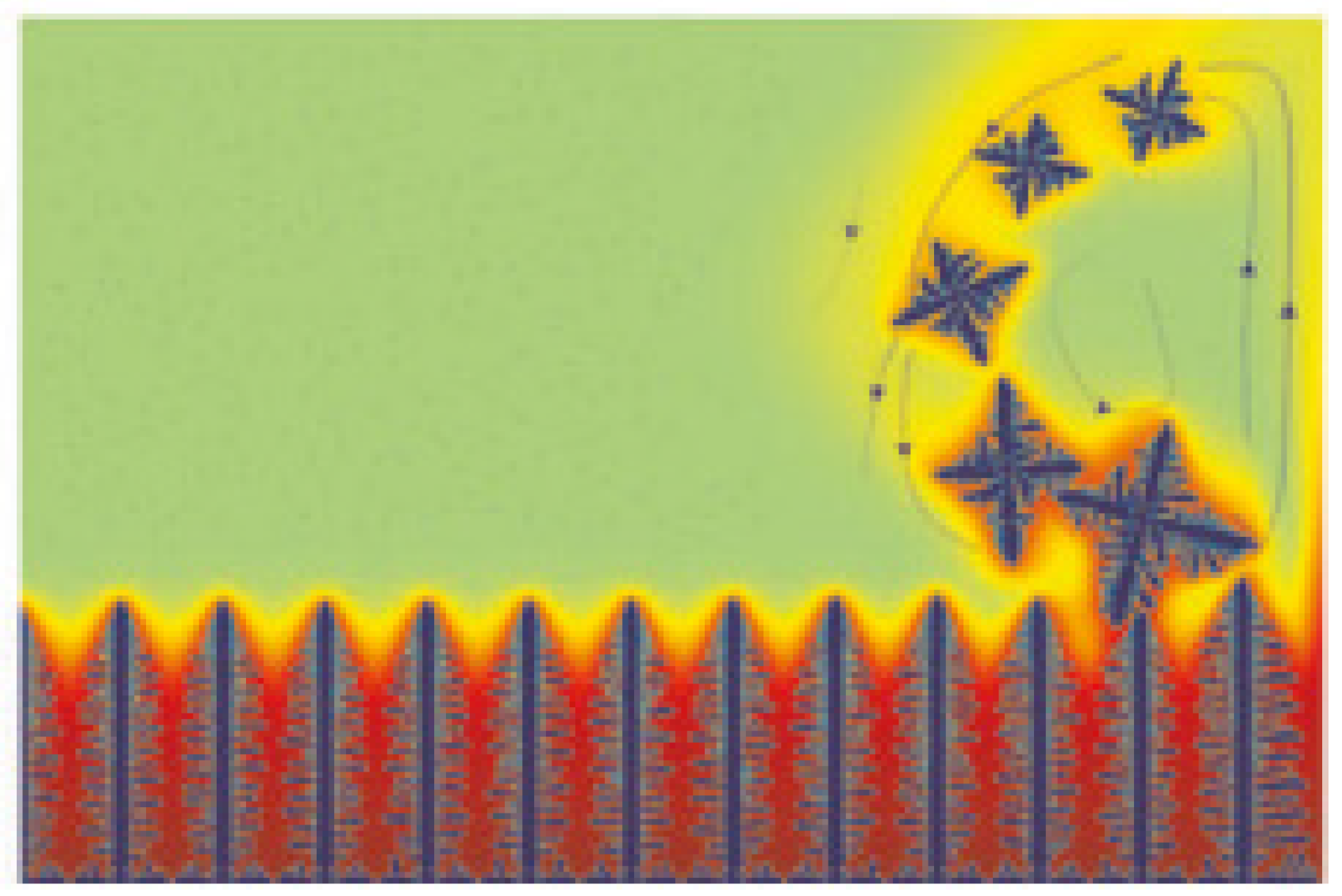
The phase field (PF) method is a diffusive interface method, which has very smooth and continuous variation across an interface between, for example, the liquid phase and the solid phase. In the LBM+CA model of phase transformation, as used in [27,29], the process of phase transformation is solely determined by the conserved field variable—solute concentration of alloy. In the PF model of phase transformation, the phase transformation is characterised by a non-conserved field variable order parameter, which smoothly varies between 1 (solid phase) and −1 (liquid phase) regarding the phase transformation between the liquid phase and solid phase. In the LBM+PF modelling of Rátkai et al. [32] and Zhan et al. [33], an Allen–Cahn equation governing the order parameters in conjunction with a Cahn–Hilliard equation governing the solute partition and transport was solved. The LBM+PF modelling was used to predict the sedimentation of equiaxed dendrites as well as the influence of natural convection on them in microgravity [32], along with the influence of forced thermosolutal convection on the growth of equiaxed dendrites [33], as shown in Figure 3.

2.4. Application of LBM Modelling

The LBM method has been widely employed in the computational modelling of a variety of material and manufacturing processes, such as casting, welding and additive manufacturing (AM).
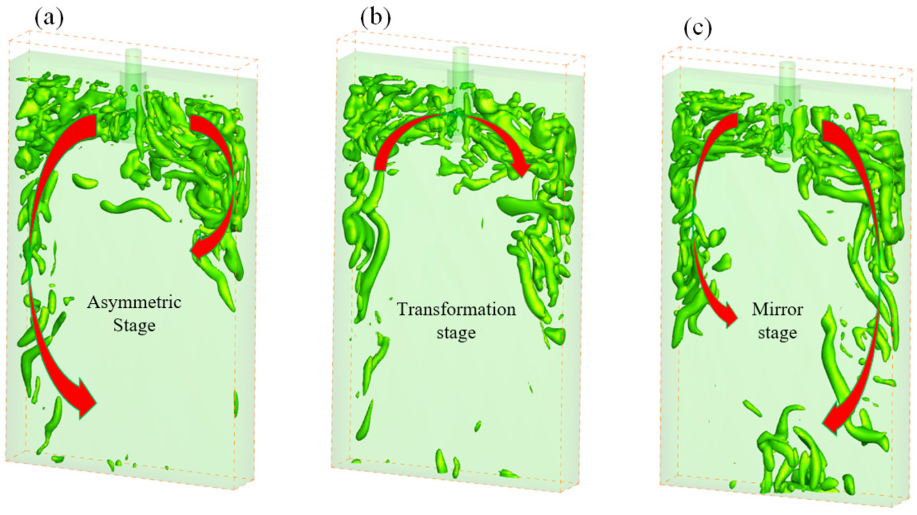
By using the large eddy simulation (LES) model to treat the turbulence, the LBM was employed in computational modelling to predict the fluid vortex and turbulence inside the submerged entry nozzle as well as near the mould wall of a continuous casting process [34]. The free surface flow problem of molten metal was treated as a melt–air two-phase flow problem, and the density of air was assumed to be zero. The collision-streaming approach was used to update the volume fraction of liquid for all computational cells, implementing the propagation of the melt–air interface during the melt flow during the continuous casting. The modelling results of the fluid vortex structure can be seen in Figure 4. In the LBM+LES modelling for the filling process of casting [35], the volume of fluid (VOF) method was employed to capture the melt–air interface and its propagation during the casting process. The overall LBM+LES+VOF model was validated against the experimental results of a Campbell box benchmark test [36].
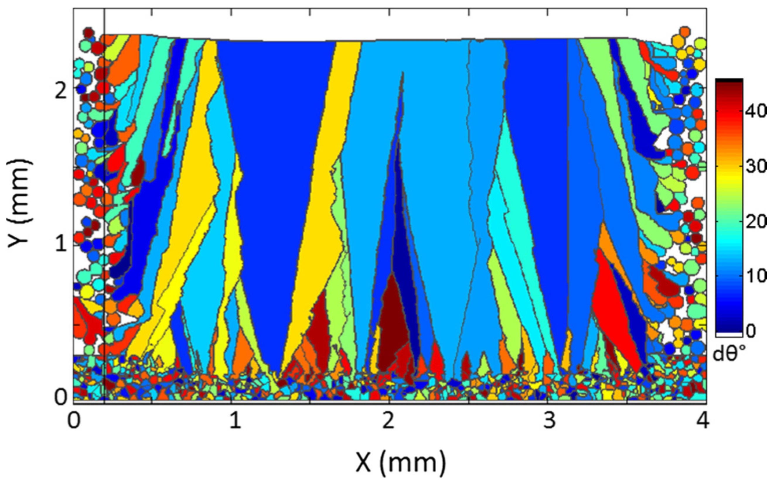
Regarding the modelling for welding, the LBM was integrated with the enthalpy method to computationally predict the remelting and, particularly, the Marangoni flow during the plasma arc welding of steels [37]. The LBM+CA method was employed to computationally predict the evolution of solidification structure during the arc welding of Inconel 601H [38]. Figure 5 shows the modelling results of the solidification structure of the melt pool, which is consistent with related experimental results.
Regarding the application of the LBM in the computational modelling of additive manufacturing (AM) processes, Korner and co-authors have made extensive publications in this field. By using the LBM method, they computationally predicted how the evaporation process may affect the heat and mass transfer of the melt pool as well as the influence of the recoil pressure on the geometry of the melt pool during the electron beam powder bed fusion (EB-PBF) AM of a Ti alloy [39]. Practically, their LBM modelling was implemented to predict the process window of EB-PBF AM regarding, as examples, how the powder bulk density [40] or hatching process strategies [41] may affect the result of the EB-PBF AM of Ti alloys. By using the LBM+CA method [42], the evolution of the solidification structure of IN718 during the EB-PBF AM was computationally predicted, as shown in Figure 6. In addition to completing some model validation, the influences of the hatching strategy on solidification structure as well as the formation of partially molten powder particles were predicted using the modelling.
By integrating the LBM with the enthalpy method [43], Chen et al. computationally predicted (in 3D) the geometry of the consolidated Ti-6Al-4V tracks manufactured using EB-PBF AM, as well as the influence of process parameters.
While having extensive advantages, the LBM has some limitations too. For example, by employing the Chapman–Enskog analysis, the LBM can be automatically reduced to the continuity equation and momentum equation of incompressible flow problems in the limit of small Knudsen number and low Mach number [44]. If the LBM needs to be employed in the modelling of compressible flow problems at high Mach numbers, special care must be taken. In the computational modelling of immiscible multi-fluid flow using LBM, spurious currents may exist in the modelling results if the density ratio between two fluids is high. Such spurious currents may increase with the density ratio, contributing to the numerical instability of the LBM [23]. Special techniques need to be developed in order to use LBM in the modelling of multi-fluid problems that have relatively large density ratios. When trying to increase the stability of LBM models, different collision models have been developed. The physical interpretations of the collision models and why they may influence the model stability are still insufficient [45]. The LBM may also have some difficulties in the computational modelling of micro-flow problems.

3. Smoothed Particle Hydrodynamics Modelling

While the LBM is a pseudo-particle method, the governing equations are solved on a structured (normally Eulerian) grid. Compared with the LBM, smoothed particle hydrodynamics (SPH) is a meshless method. Rather than using any structured or unstructured computational grid, the SPH method uses moving points of integration to solve related governing equations. As was systematically explained by Monaghan [46], the SPH method discretizes the target material into a number of material elements. Each material element is represented by a pseudo-particle, which represents the actual macroscopic properties of a material element such as mass, thermal energy, momentum, etc. Because the SPH method is a fully Lagrangian method, the governing equations of target problems are formulated using total derivatives in the style of
d A d t = f ( r , t )
where A is a dependent variable of interest and f is a function that formulates how A changes with spatial position r and time t.
The SPH method firstly calculates the volume-averaged value of the dependent variable of interest using the formula
A ¯ ( r ) = A ( r ) · W ( r r , h ) d r
where W is called the smoothing kernel, which takes the role of a weighting function; h relates to the radius of coverage of the smoothing kernel; r represents the position of interest and r represents the locations near the position of interest. The discrete form of this equation can be presented as
A ¯ ( r a ) = b A b m b ρ b W ( r a r b )
where a represents the particle of interest, b represents the particles near particle a and m represents the mass of a pseudo-particle. When such equation is substituted into related differential governing equations (e.g., the Naiver–Stokes equation), the differential equations can be converted to the corresponding algebraic equation systems. In the algebraic equation system, related sums need to be calculated for the particles that are within the radius of coverage of the smoothing kernel, which is normally proportional to h. The reason is that the smoothing kernel W rapidly decreases with inter-particle distance, and it becomes zero beyond the radius of coverage of the smoothing kernel. A variety of smoothing kernel functions have been developed for different applications, such as the Gaussian kernel, cubic spline kernel, Wendland kernel, Cubic B-spline kernel, Quintic-spline, etc. A review of them can be seen in [46,47].
Regarding the computational modelling of single-phase fluid flow and heat transfer problems, this can be performed by substituting the above formulation of A ¯ ( r a ) into, as examples, the Naiver–Stokes equation and the energy equation. By doing so, it can convert the corresponding partial differential equations to the corresponding algebraic equations, which employ the particle of interest and the particles nearby within the radius of coverage of the smoothing kernel. Regarding the SPH modelling of multi-phase problems of such as fluid flow and heat transfer, different pseudo-particles have the information of the properties of different phases. For example, the liquid phase pseudo-particles have the information such as density and viscosity of liquid phase, and so on for gas phase and solid phase. Regarding the interface between the liquid phase and gas phase, it has a thickness of zero, as there is no pseudo-particle that can be simultaneously partially liquid phase and partially gas phase in SPH modelling.
Regarding the SPH modelling of phase transformation, particularly, e.g., the remelting and solidification processes, the most widely used approach is to combine the SPH method for fluid flow and heat transfer with the enthalpy method for phase transformation. The governing equations are [48]
d H a d t = b 4 m b ρ a ρ b k a k b T a b k a + k b r a b · a W a b r a b 2 + η 2
H = 0 T C p d T + L [ 1 f s ( T ) ]
where T is temperature (in Kelvin), L is the latent heat of fusion, k is the thermal conductivity, T a b = T a T b , f s is the solid fraction, C p is the specific heat capacity and r a b is the vector pointing from particle a to particle b. η is a constant that has a very small value for the purpose of assuring a nonzero value of the denominator. The enthalpy of each-pseudo particle (H) is firstly calculated by solving the energy equation. Then, the value of enthalpy is used to calculate the value of solid fraction.

3.1. Application of SPH Modelling in Casting

The SPH method in conjunction with the enthalpy method (SPH+Enthalpy method) has been widely employed in the computational modelling of casting. The research team of Cleary has developed a computer programme implementing the SPH+Enthalpy method in the computational modelling for casting with focus on, e.g., the filling process, heat transfer and defect formation during high-pressure die casting of automobile components [48] (as shown in Figure 7) and thin-walled components [49] and defect formation in low-pressure die casting [50]. In a review [51], the application of SPH in the computational modelling of industrial flow problems was extensively discussed. By using sand casting as the background [52], the SPH+Enthalpy method was used to predict the solidification process and the results were compared with the modelling results using the finite element method (FEM). Because the SPH method is a fully Lagrangian method, it can be used to computationally predict the formation and entrainment of oxide films during, e.g., gravity die casting [53]. This is a particular strength of such a meshless Lagrangian method.
The LS-DYNA software of ANSYS recently included an SPH solver. It can be used to computationally predict the fluid flow and mechanical responses of materials as well as the fluid–structure interaction. It was used to predict the filling process of, as well as potential defects arising from, semi-solid metal casting [54].

3.2. Application of SPH Modelling in Welding

When the mechanisms of heat transfer resulting from an external heat source and fluid flow driven by Marangoni effects can be considered in the modelling, the SPH method can be employed in the computational modelling of fusion welding processes, e.g., to predict the evolution of weld pool geometry and temperature field during the welding process [55]. In addition to fluid dynamics, the overall concept of SPH can also be used to solve the governing equations of solid mechanics by formulating the elasticity and plasticity of the target material. By integrating the SPH model of solid mechanics and implementing the elastoplastic constitutive model with the SPH model of fluid flow and heat transfer, SPH modelling was developed for the arc welding of a grooved weld of aluminium alloy employing filler metal [56]. By solving the Johnson–Cook constitutive relation, the SPH method was used to computationally predict the high-velocity impact welding of aluminium plates [57]. In this paper, the authors, in particular, compared the modelling results and computational efficiency of SPH modelling with the conventional ALE approach based on the FE method. Compared with the ALE method, SPH proved to be able to reflect the formation of delicate microscopic jets of material, which cannot be carried out using the ALE+FE method. Because the SPH method can be used to numerically solve the governing equations of solid material deformation, heat transfer, fluid flow and surface problems (such as surface tension, surface oxidation, surface topological changes etc.) and the respective SPH modelling can be very easily coupled together, it is very suitable for the modelling of friction stir welding. For example, it was used to predict the weld temperature, plastic strain and residual stress of aluminium alloy dissimilar friction stir welding [58].

3.3. Application of SPH Modelling in Additive Manufacturing

Recently, there have been increasingly more applications of the SPH method in the computational modelling of AM processes. By considering the processes of laser/electron beam heating, powder remelting, melt flow and heat transfer, as well as melt solidification, the SPH method has been employed in the computational prediction of the temperature field, melt flow field and pore formation for laser beam powder bed fusion (LB-PBF) AM [59,60] as well as direct energy deposition (DED) AM [61]. In addition to modelling the behaviour of the liquid phase during the AM, computational modelling of the responses of the solid particles of the metal powder during the AM also needs to be performed. Regarding the interaction between the molten metal and solid particles of the metal powder, Fuchs et al. [62] developed a versatile SPH model and corresponding powerful software, which can predict such thermomechanical interactions during many different processes of AM such as binder jetting, material jetting, directed energy deposition and PBF. In the paper, the authors demonstrated the potentially wide application of the SPH model in many different fields of AM. In this model, the actual solid particles of the metal powder were assumed to be rigid bodies. The powder dynamics were mathematically formulated using the linear momentum equation and angular momentum equation. The influence of the melt flow on the powder dynamics was considered by employing a coupling force term and coupling torque term in the powder momentum equations. The interaction between solid particles of the metal powder was implemented by considering a solid particle contact force term and contact torque term in the equations. The results of applying such integrated modelling in LB-PBF AM can be seen in Figure 8.
In order to improve the computational efficiency of the SPH modelling, a multi-resolution SPH model was developed for modelling the LB-PBF AM [63]. In this model, the volume of each SPH pseudo-particle and the smoothing length change from place to place in the overall simulation domain were considered. The pseudo-particles have better resolution where the highly dynamic processes happen, such as the powder remelting, melt flow and melt solidification, especially in the close vicinity of the dynamically evolving melt pool. Such a multi-resolution approach can make the SPH modelling more computationally efficient. The limitation of this method is that the resolution of the pseudo-particles can only be refined by using the particle-splitting method. The refined pseudo-particles cannot be coarsened. In an improved fully adaptive SPH model [64], the refined pseudo-particles can be coarsened when/where necessary according to a chosen standard. One such advanced adaptive SPH method was used to successfully predict the melt pool dynamics and surface profile of alloys manufactured using multi-track LB-PBF AM.

4. Discrete Element Method

During the PBF AM, there are two different processes: powder spreading and powder sintering. Because the powder spreading process has influence on the properties of the powder bed, the aforementioned SPH computational modelling for powder sintering needs the modelling results of the powder spreading process as inputs. Recently, the discrete element method (DEM) has become the most widely used method for modelling the powder spreading processes of AM.
In the DEM, each pseudo-particle represents one solid particle of the metal powder. As explained by Cleary [65], the DEM method formulates the interaction between pseudo-particles by using the spring–dashpot contact model, which determines the collisional normal force F n   and tangent force F t   by using, e.g., the relative velocity and overlap of the two neighbouring pseudo-particles as inputs. The normal force and tangential force are formulated as [65]
F n = k n Δ x + C n v n
F t = m i n { μ F n , ( k t v t Δ t + C t v t ) }
where Δ x is the overlap of two neighbouring pseudo-particles, C is the damping coefficient, k is the spring stiffness, μ is the coefficient of friction,   Δ t is the size of time step and v is the relative velocity. When the pseudo-particles represent physically solid particles that are smaller than 100 µm, the effect of the Van der Waals force F v   cannot be neglected. It can be formulated as [66]
F v = H a 6 · 64 R i 3 R j 3 ( h + R i + R j ) ( h 2 + 2 h R i + 2 h R j ) 2 ( h 2 + 2 h R i + 2 h R j + 4 R i R j ) 2 · n i j
where H a is the Hamaker constant, R is the radius of the particle, h is the distance between the surfaces of particles i and j and nij is the unit vector pointing from particle i to particle j.
If the influence of evaporation on the mass of target material during the AM process can be neglected, the mass of the pseudo-particle representing a solid metal particle of the metal powder in the DEM can be assumed to be identical to the mass of the pseudo-particle representing a fluid element of the molten metal in the SPH method. Because the DEM method and SPH method are both meshless particle-based Lagrangian computational methods, it is very natural to integrate the DEM modelling for solid powder flow with the SPH model for fluid flow. One such integrated method was used to computationally predict the interaction between solid particles and slurry in a semi-autogenous mill and a Hardinge pilot mill [65]. By using the DEM to predict the metal powder spreading process and using the SPH method to predict the metal powder sintering process, the DEM+SPH integrated method was employed to predict the processes of heat transfer and phase transformation during the LB-PBF AM of Ti alloy [67]. In 2D and 3D simulations, the DEM+SPH integrated method was used to predict the influence of the capillary number on the surface profile of the sintered alloy during LB-PBF AM.

5. Particle Finite Element Method

In the particle finite element method (PFEM) [68], the target material is firstly discretized into a number of pseudo-particles. The pseudo-particles can move as a result of material flow or deformation, and they carry information such as momentum, enthalpy and other properties of the corresponding material elements. When trying to solve the governing equations using the PFEM, the pseudo-particles take the role of computational nodes and form a conventional finite element mesh. The conventional finite element method is then used to solve the governing equations. The application of the PFEM in the computational modelling of granular material was validated using the dam break case study.
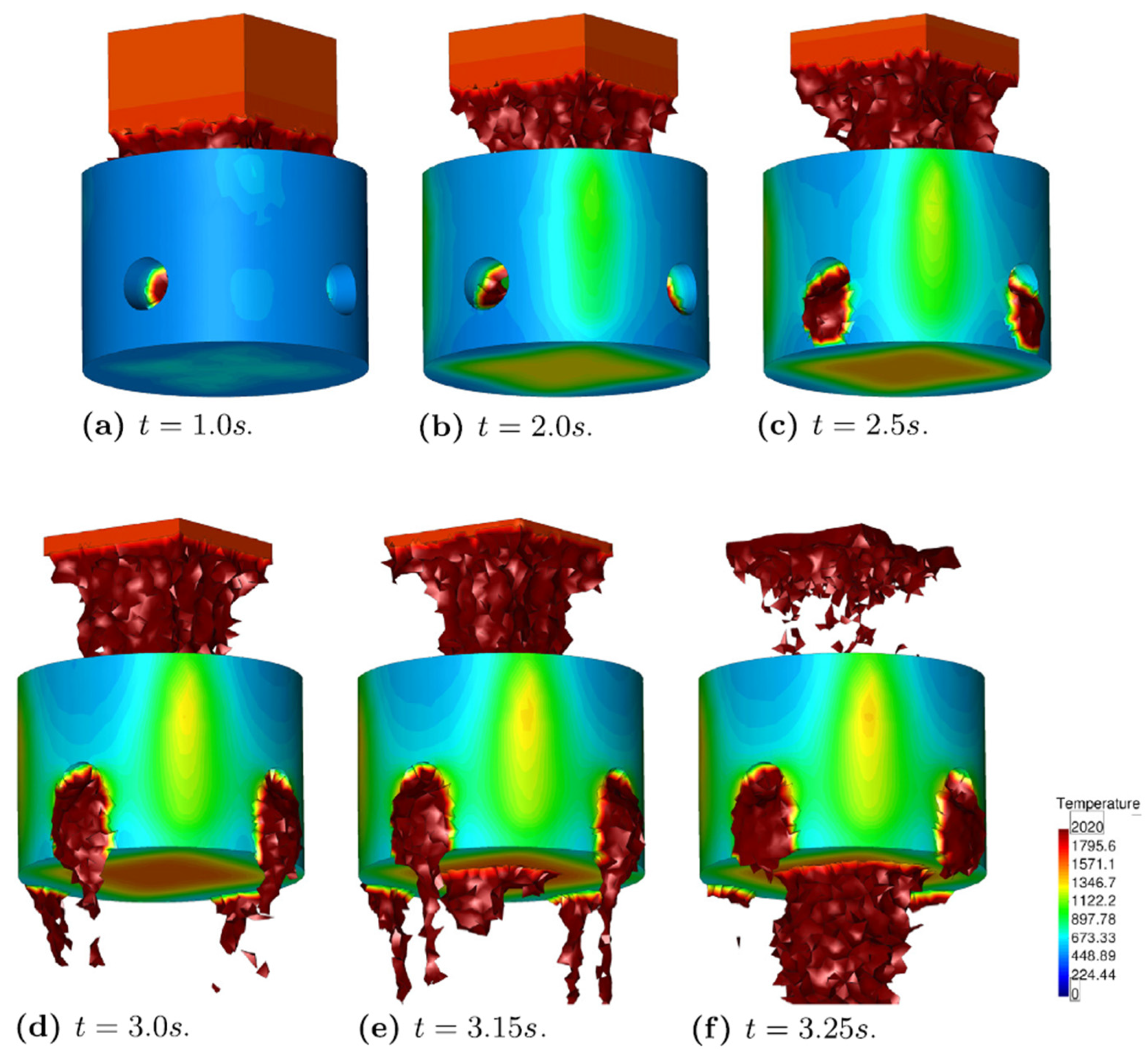
Regarding predicting the process of remelting or solidification, overall, two different methods have been implemented in PFEM modelling. In the effort to develop a self-adaptive remeshing scheme of the PFEM, a very simplified model of phase transformation was employed [69]. In this model, the solid fraction of material was assumed to be a linear function of temperature between the liquidus temperature and solidus temperature of the target alloy. Extensive validation of such PFEM modelling was completed by using case studies, such as Marangoni effect-driven cavity flow and the remelting and melt flow of gallium [70]. In a more complex model of phase transformation, the concept of the enthalpy method was used in conjunction with some variations [71]. This integrated the models of heat transfer, remelting/solidification and constitutive behaviour of the target material in the PFEM modelling to predict the process of nuclear core melt in an accident (as shown in Figure 9).
By replacing the element birth and death approach of the conventional finite element method, the PFEM was successfully employed in the computational prediction of the deflection and residual stress of a cantilever beam and three-dimensional block manufactured using laser AM [72].

6. Discussion and Conclusions

In this paper, four particle-based methods are reviewed regarding their applications, such as welding, casting and AM. The methods include the LBM, SPH, DEM and PFEM. It is worth highlighting that the terminology “particle” refers to pseudo-particles. The pseudo-particles normally represent a material element. The specific choice of the size of the material element depends on the requirement of the model development and application. For the computational modelling of the flow of granular material, the pseudo-particles are normally set to correspond to individual solid particles of the target material. For the computational modelling of heat transfer and flow of liquid phase, the size of the material elements normally depends on the spatial resolution of the computational modelling. Among these four methods, the LBM and PFEM are mesh-based methods. They must employ a computational grid (in conjunction with corresponding node connectivity) when solving the governing equations. Compared with them, the SPH and DEM methods are meshless methods. When solving the governing equations, the SPH and DEM only consider the interaction between the pseudo-particle of interest and other pseudo-particles nearby. Although the LBM is a particle-based method, its pseudo-particles are fixed on the nodes of the computational grid and do not actually move. The variation in the probability distribution function reflects the flow/displacement of material elements in the LBM. In the SPH, DEM and PFEM, however, the pseudo-particles move, which directly reflects the flow/displacement of corresponding material elements. Overall, the LBM is an Eulerian method but the SPH, DEM and PFEM methods are Lagrangian methods.
Because the LBM employs a concept that is similar to the concept of CA to some extent [22], it is very convenient to integrate the LBM with the CA-type models or the Potts-type models in the computational modelling of flow/heat transfer/microstructural problems. In the LBM, the macroscopic properties of materials (such as density) are calculated by using the values of the probability distribution function. Therefore, there is smooth variation in material properties at the interface between two different phases. This means that the LBM employs a diffusive-interface concept when implicitly capturing the interfaces in the modelling of multiphase problems. There are several different approaches of the LBM that can be used to deal with the multiphase problems, such as the RK colour gradient approach, Shan–Chen multiphase approach and the free energy approach [23]. In the SPH, DEM and PFEM, different pseudo-particles can represent the material elements of different phases (such as liquid, solid, gas). Therefore, they employ the sharp-interface concept when explicitly tracking the interfaces in multiphase modelling.
Regarding the meshless methods, i.e., the SPH and DEM, extensive computational cost has to be spent on the particle search process. For example, in the SPH methods, all particles that are within the radius of coverage of the smoothing kernel must be found and included in the calculation of related sums (for the calculations of, e.g., the first derivatives and second derivatives). Such a search process takes time. A similar thing happens to the solution process of the DEM. In the PFEM, the Delaunay tessellation method is widely employed to create the FEM mesh for each time step. Such frequent regeneration of the computational mesh costs computational time too.
When using meshless particle-based methods to run computational modelling, it is ideal that the number density of the pseudo-particles is spatially uniform unless an adaptive spatial resolution scheme is employed on purpose. Therefore, it is necessary to avoid over-accumulation or over-depletion of the pseudo-particles during the computations. In DEM modelling, over-accumulation of the pseudo-particles can be easily avoided. The reason is that excessive repulsive force is generated when two pseudo-particles become too close, according to the spring–dashpot concept. In SPH modelling, however, special care must be taken to avoid the over-accumulation of the pseudo-particles. The reason is that the inter-particle repulsive force results from the derivative of the smoothing kernel. For many smoothing kernels, when two pseudo-particles become too close to one another, the inter-particle repulsive force may decrease if the two pseudo-particles tend to end up even closer. Such a problem is called tensile instability in SPH modelling. Special care has to be taken to decrease the influence of the tensile instability on the modelling results. Moreover, special care has to be taken to try to make the spatial distribution of the pseudo-particles uniform in SPH modelling. One example is that the pseudo-particles are slightly shifted off the streamlines every one or two steps [73].
Regarding the modelling of remelting and solidification, the enthalpy method has been widely employed in computational modelling in conjunction with these four methods. One reason is that the implementation of the enthalpy method is straightforward, since it only needs a very small number of material thermal properties as inputs. The other reason is that all these four methods perform computational modelling at the mesoscale or macroscale, which is exactly the spatial scale at which the enthalpy method is valid. Moreover, the enthalpy method is independent of the connectivity between pseudo-particles. Due to these reasons, the enthalpy method for modelling phase transformation can be integrated with either mesh-based methods or meshless methods, and with either Eulerian methods or Lagrangian methods.
Regarding the interaction between the four methods, SPH and DEM have been extensively integrated in the modelling of problems that involve both granular material flow and fluid flow. The LBM is very easily integrated with mesh-based modelling methods such as, but not limited to, the CA- and Potts-type Monte Carlo models. Many techniques of the conventional finite element modelling can be employed in PFEM modelling.
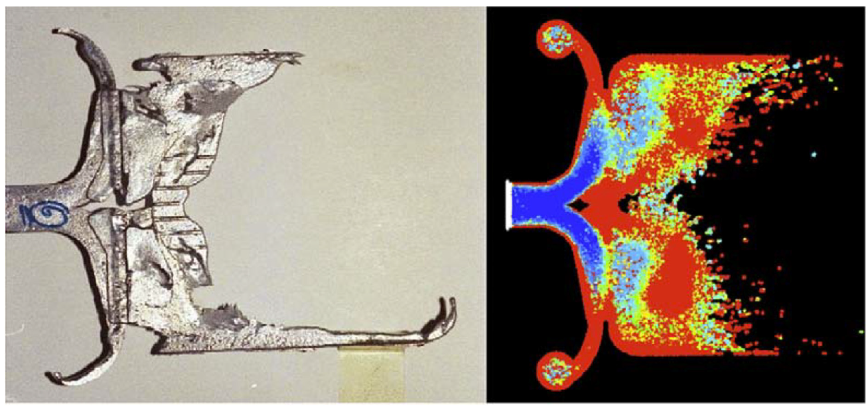
Some related features of these four particle-based modelling methods are summarized in Table 1. Regarding their employment in the computational modelling of material processing or manufacturing that involves solidification or remelting, it can be seen that they are very widely coupled with the enthalpy method. Because the CA and PFM are both mesh-based (normally Eulerian) methods, the coupling of them with SPH, DEM or PFEM has been very rare up to date. If we compare these particle-based methods with the conventional modelling methods based on continuum mechanics (such as the FE method or finite volume CFD method), it can be seen that the particle-based methods normally are less computationally efficient. The reason is that the particle-based methods normally need to take some extra effort to deal with particular issues of their own, in addition to numerically solving the governing equations. For example, the SPH and DEM methods must spend some computational resources on the near pseudo-particle search (for the calculation of sums). The SPH computations also have to make some extra effort to redistribute the pseudo-particles to avoid over-accumulation or -depletion. The PFEM method must spend appreciable time and computational resources on regenerating the dynamic FE mesh during the computations. The conventional FE methods or finite volume-based CFD models on the macroscale normally do not have such hassles. They do not contain the concept (or idea) of interactions between the pseudo-particles. They normally only need to directly numerically solve the constitutive equations or the Naiver–Stokes equations on a computational mesh after the boundary conditions and material properties are set. However, after paying the cost of extra computational resources and time, the particle-based methods can be used to characterise some small-scale delicate properties of the target material or process (such as the material microstructure shown in Figure 5 and melt–particle interaction shown in Figure 7) while using a much larger piece of material as the background. If the particle-based methods are compared with microscopic discrete outlook methods (such as the MD method), it can be seen that the particle-based methods have much better computational efficiency because they do not need to explicitly/directly consider the microscopic interactions between atoms and molecules.
Recently, researchers have tried to use the increasingly popular machine learning techniques to support or enhance the particle-based computational modelling methods. For example, surrogate collision models were developed using artificial neural networks (NN) to implement the LBM modelling of non-hydrodynamic systems [74]. A convolutional neural network was used to successfully increase the speed of DEM computational speed by orders of magnitude [75]. As is known to all, choosing an appropriate smoothing kernel is very critical to the success of SPH modelling. For this purpose, a machine learning approach was developed to find the optimal anisotropic smoothing kernel of SPH modelling [76].
When trying to complete the computational modelling for a relatively complex system while simultaneously focusing on the phenomena at multiple spatial scales, multiscale computational modelling becomes necessary. For example, towards a smaller spatial scale, as was reviewed by Liu and Liu [77], extensive efforts have been made to incorporate SPH modelling with MD modelling to solve some challenging solid mechanics problems (such as fracture mechanics) and flow problems in micro- and nanoscale systems. The LBM was directly coupled with the MD method for modelling steady-state isothermal flow problems [78]. A hierarchical multiscale method was invented to bridge the FEM with the MD method, to computationally predict the mechanical responses of a single crystal copper [79]. The same concept can be potentially borrowed to couple the PFEM with the MD method. Towards a larger spatial scale, the SPH method and FEM were coupled to computationally predict the fluid–structure interactions [80]. The FEM and DEM were coupled to computationally analyse a solid granule medium forming technique [81]. The LBM was combined with FEM to computationally predict unsaturated poroelastic behaviour of heterogeneous media [82].
Overall, the LBM, SPH, DEM and PFEM methods have been widely employed in the computational modelling of casting, welding and AM. By using the unique properties of the particle-based methods, the application of them in related computational modelling research has benefited the body-of-knowledge and related industries.

Funding

This publication has emanated from research conducted with the financial support of the Science Foundation Ireland under Grant number 16/RC/3872. For the purpose of Open Access, the author has applied a CC BY public copyright licence to any Author Accepted Manuscript version arising from this submission.

Data Availability Statement

No new data were created during this work.

Conflicts of Interest

The author declares no conflict of interest.

References

  1. Zhang, X.; Chen, Z.; Liu, Y. The Material Point Method: A Continuum-Based Particle Method for Extreme Loading Cases; Academic Press: Beijing, China, 2016. [Google Scholar]
  2. Smith, M. ABAQUS/Standard User’s Manual, Version 6.9; Dassault Systems Simulia Corp.: Providence, RI, USA, 2009. [Google Scholar]
  3. Ruffoni, D.; Van Lenthe, G. 3.10 Finite Element Analysis in Bone Research: A Computational Method Relating Structure to Mechanical Function. Compr. Biomater. II 2017, 3, 169–196. [Google Scholar]
  4. Moukalled, F.; Mangani, L.; Darwish, M. The Finite Volume Method in Computational Fluid Dynamics: An Advanced Introduction with OpenFOAM and Matlab; Springer International Publishing: Cham, Switzerland, 2015. [Google Scholar]
  5. Osher, S.; Fedkiw, R. Level Set Methods: An Overview and Some Recent Results. J. Comput. Phys. 2001, 169, 463–502. [Google Scholar] [CrossRef] [Green Version]
  6. Blanc, C.; Aubert, I. Mechanics—Microstructure—Corrosion Coupling: Concepts, Experiments, Modeling and Cases; ISTE Press—Elsevier: Amsterdam, The Netherlands, 2019. [Google Scholar]
  7. Haff, P. Discrete Mechanics. In Granular Matter; Mehta, A., Ed.; Springer: New York, NY, USA, 1994. [Google Scholar]
  8. Tuckerman, M.; Martyna, G. Understanding Modern Molecular Dynamics: Techniques and Applications. J. Phys. Chem. B 2000, 104, 159–178. [Google Scholar] [CrossRef]
  9. Papanikolaou, M.; Salonitis, K.; Jolly, M.; Frank, M. Large-Scale Molecular Dynamics Simulations of Homogeneous Nucleation of Pure Aluminium. Metals 2019, 9, 1217. [Google Scholar] [CrossRef] [Green Version]
  10. Yang, H.; Yu, K.; Mu, X.; Wei, Y.; Guoa, Y.; Qi, H. Molecular dynamics studying on welding behavior in thermosetting polymers due to bond exchange reactions. RSC Adv. 2016, 6, 22476–22487. [Google Scholar] [CrossRef] [Green Version]
  11. Chang, Q.; Xie, J.; Mao, A.; Wang, W. Study on Interface Structure of Cu/Al Clad Plates by Roll Casting. Metals 2018, 8, 770. [Google Scholar] [CrossRef] [Green Version]
  12. Stavropoulos, P.; Panagiotopoulou, V. Developing a Framework for Using Molecular Dynamics in Additive Manufacturing Process Modelling. Modelling 2022, 3, 189–200. [Google Scholar] [CrossRef]
  13. Mouvet, F.; Villard, J.; Bolnykh, V.; Rothlisberger, U. Recent Advances in First-Principles Based Molecular Dynamics. Acc. Chem. Res. 2022, 55, 221–230. [Google Scholar] [CrossRef]
  14. Harvey, J.; Asimow, P. Current limitations of molecular dynamic simulations as probes of thermo-physical behavior of silicate melts. Am. Mineral. 2015, 100, 1866–1882. [Google Scholar] [CrossRef]
  15. Mahgoub, A.; Ghani, S. Numerical and experimental investigation of utilizing the porous media model for windbreaks CFD simulation. Sustain. Cities Soc. 2021, 65, 102648. [Google Scholar]
  16. Bakhshian, S.; Hosseini, S.; Shokri, N. Pore-scale characteristics of multiphase flow in heterogeneous porous media using the lattice Boltzmann method. Sci. Rep. 2019, 9, 3377. [Google Scholar] [CrossRef] [PubMed] [Green Version]
  17. Neethling, S.; Barker, D. Using Smooth Particle Hydrodynamics (SPH) to model multiphase mineral processing systems. Miner. Eng. 2016, 90, 17–28. [Google Scholar] [CrossRef]
  18. Frissane, H.; Taddei, L.; Lebaal, N.; Roth, S. 3D smooth particle hydrodynamics modeling for high velocity penetrating impact using GPU: Application to a blunt projectile penetrating thin steel plates. Comput. Methods Appl. Mech. Eng. 2019, 357, 112590. [Google Scholar] [CrossRef]
  19. Snelling, B.; Piggott, M.; Collins, G.; Neethling, S. Using Smoothed Particle Hydrodynamics to investigate the effect of complex slide rheology on landslide generated waves. Geophys. Res. Abstr. 2018, 20, 8848. [Google Scholar]
  20. Idelsohn, S.; Oñate, E.; Pin, F.; Calvo, N. Fluid–structure interaction using the particle finite element method. Comput. Methods Appl. Mech. Eng. 2006, 195, 2100–2123. [Google Scholar] [CrossRef] [Green Version]
  21. Xu, L.; Luo, K.; Zhao, Y.; Fan, J.; Cen, K. Influence of particle shape on liner wear in tumbling mills: A DEM study. Powder Technol. 2019, 350, 26–35. [Google Scholar] [CrossRef]
  22. Raabe, D. Overview of the lattice Boltzmann method for nano- and microscale fluid dynamics in materials science and engineering. Model. Simul. Mater. Sci. Eng. 2004, 12, R13–R46. [Google Scholar] [CrossRef]
  23. Sudhakar, T.; Das, A.K. Evolution of Multiphase Lattice Boltzmann Method: A Review. J. Inst. Eng. India Ser. C 2020, 101, 711–719. [Google Scholar] [CrossRef]
  24. He, X.; Luo, L.S. Theory of the lattice Boltzmann method: From the Boltzmann equation to the lattice Boltzmann equation. Phys. Rev. E 1997, 56, 6811. [Google Scholar] [CrossRef] [Green Version]
  25. Perumal, D.A.; Dass, A.K. A Review on the development of lattice Boltzmann computation of macro fluid flows and heat transfer. Alex. Eng. J. 2015, 54, 955–971. [Google Scholar] [CrossRef] [Green Version]
  26. Semma, E.A.; Ganaoui, M.E.; Bennacer, R. Lattice Boltzmann method for melting/solidification problems. Comptes Rendus Mec. 2007, 335, 295–303. [Google Scholar] [CrossRef]
  27. Sun, D.; Zhu, M.; Pan, S.; Raabe, D. Numerical Modeling of Dendritic Growth in Alloy Solidification with Forced Convection. Int. J. Mod. Phys. B 2009, 23, 1609–1614. [Google Scholar] [CrossRef]
  28. Huang, R.; Wu, H. Phase interface effects in the total enthalpy-based lattice Boltzmann model for solid–liquid phase change. J. Comput. Phys. 2015, 294, 346–362. [Google Scholar] [CrossRef]
  29. Sun, D.K.; Zhu, M.F.; Pan, S.Y.; Yang, C.R.; Raabe, D. Lattice Boltzmann modeling of dendritic growth in forced and natural convection. Comput. Math. Appl. 2011, 61, 3585–3592. [Google Scholar] [CrossRef] [Green Version]
  30. Lee, W.; Bae, J.; Lee, H.; Kang, S.-H.; Yoon, J. Numerical simulation of dendritic growth and porosity evolution in solidification of Al-Cu alloy with lattice Boltzmann—Cellular automata method. J. Alloys Compd. 2022, 929, 167233. [Google Scholar] [CrossRef]
  31. Reuther, K.; Rettenmayr, M. Perspectives for cellular automata for the simulation of dendritic solidification—A review. Comput. Mater. Sci. 2014, 95, 213–220. [Google Scholar] [CrossRef]
  32. Rátkai, L.; Pusztai, T.; Gránásy, L. Phase-field lattice Boltzmann model for dendrites growing and moving in melt flow. Comput. Mater. 2019, 5, 113. [Google Scholar] [CrossRef] [Green Version]
  33. Zhan, C.; Chai, Z.; Shi, B.; Jiang, P.; Geng, S.; Sun, D. A diffuse-interface lattice Boltzmann method for the dendritic growth with thermosolutal convection. Commun. Comput. Phys. 2023, 33, 1164–1188. [Google Scholar] [CrossRef]
  34. Zhao, P.; Piao, R. Lattice Boltzmann Method Modeling of the Evolution of Coherent Vortices and Periodic Flow in a Continuous Casting Mold. Metals 2022, 12, 572. [Google Scholar] [CrossRef]
  35. Zhang, Y.J.; Qian, X.W.; Zhou, J.X.; Yin, Y.J.; Shen, X.; Ji, X.Y.; Huang, J.L. Simulation of casting filling process using the lattice Boltzmann method. IOP Conf. Ser. Mater. Sci. Eng. 2019, 529, 012061. [Google Scholar] [CrossRef]
  36. Sirrell, B.; Holliday, M.; Campbell, J. Benchmark testing the flow and solidification modeling of AI castings. JOM 1996, 48, 20–23. [Google Scholar] [CrossRef]
  37. Feng, Y.; Zhoua, J.; Cai, J.; Zhang, X.; Wu, C. A 3-D lattice Boltzmann analysis of weld pool dynamic behaviors in plasma arc welding. Appl. Therm. Eng. 2018, 139, 623–635. [Google Scholar] [CrossRef]
  38. Shi, F.; Zheng, Z.; He, M.; Lei, Y.; Guo, D.; Yu, J. Fluid flow behavior and solidification process of welding pool under rapid cooling condition based on cellular automata-lattice Boltzmann method (CA-LBM) couple model. Mater. Werkst. 2020, 51, 862–877. [Google Scholar] [CrossRef]
  39. Klassen, A.; Scharowsky, T.; Korner, C. Evaporation model for beam based additive manufacturing using free surface lattice Boltzmann methods. J. Phys. D Appl. Phys. 2014, 47, 275303. [Google Scholar] [CrossRef]
  40. Rausch, A.M.; Küng, V.E.; Pobel, C.; Markl, M. Predictive Simulation of Process Windows for Powder Bed Fusion Additive Manufacturing: Influence of the Powder Bulk Density. Materials 2017, 10, 1117. [Google Scholar] [CrossRef] [Green Version]
  41. Mark, M.; Ammer, R.; Rude, U.; Korner, C. Numerical investigations on hatching process strategies for powder-bed-based additive manufacturing using an electron beam. Int. J. Adv. Manuf. Technol. 2015, 78, 239–247. [Google Scholar] [CrossRef] [Green Version]
  42. Rai, A.; Mark, M.; Körner, C. A coupled Cellular Automaton–Lattice Boltzmann model for grain structure simulation during additive manufacturing. Comput. Mater. Sci. 2016, 124, 37–48. [Google Scholar] [CrossRef]
  43. Chen, D.; Chen, W.; Liu, Y.; Sun, D. A Two-Relaxation-Time Lattice Boltzmann Model for Electron Beam Selective Melting Additive Manufacturing. Front. Mater. 2022, 9, 885481. [Google Scholar] [CrossRef]
  44. McNamara, G.R.; Garcia, A.L.; Alder, B.J. A Hydrodynamically Correct Thermal Lattice Boltzmann Model. J. Stat. Phys. 1997, 87, 1111–1121. [Google Scholar] [CrossRef]
  45. Coreixas, C.; Wissocq, G.; Chopard, B.; Latt, J. Impact of collision models on the physical properties and the stability of lattice Boltzmann methods. Phil. Trans. R. Soc. A 2019, 378, 0397. [Google Scholar] [CrossRef]
  46. Monaghan, J.J. Smoothed particle hydrodynamics. Rep. Prog. Phys. 2005, 68, 1703–1759. [Google Scholar] [CrossRef] [Green Version]
  47. Xu, F.; Wang, J.; Yang, Y.; Wang, L.; Dai, Z.; Han, R. On methodology and application of smoothed particle hydrodynamics in fluid, solid and biomechanics. Acta Mech. Sin. 2023, 39, 722185. [Google Scholar] [CrossRef]
  48. Cleary, P.; Ha, J.; Prakash, M.; Nguyen, T. 3D SPH flow predictions and validation for high pressure die casting of automotive components. Appl. Math. Model. 2006, 30, 1406–1427. [Google Scholar] [CrossRef] [Green Version]
  49. Cleary, P.W.; Savage, G.; Ha, J.; Prakash, M. Flow analysis and validation of numerical modelling for a thin walled high pressure die casting using SPH. Comput. Part. Mech. 2014, 1, 229–243. [Google Scholar] [CrossRef] [Green Version]
  50. Cleary, P.W. Extension of SPH to predict feeding, freezing and defect creation in low pressure die casting. Appl. Math. Model. 2010, 34, 3189–3201. [Google Scholar] [CrossRef]
  51. Cleary, P.W.; Harrison, S.M.; Sinnott, M.D.; Pereira, G.G.; Prakash, M.; Cohen, R.C.Z.; Rudman, M.; Stokes, N. Application of SPH to Single and Multiphase Geophysical, Biophysical and Industrial Fluid Flows. Int. J. Comput. Fluid Dyn. 2021, 35, 22–78. [Google Scholar] [CrossRef]
  52. He, Y.; Zhou, Z.-Y.; Cao, W.-J.; Yang, D.-Z. Numerical Simulation of Solidification by SPH in Sand Cast Process. Adv. Mater. Res. 2011, 314–316, 614–619. [Google Scholar] [CrossRef]
  53. Ellingsen, K.; Coudert, T.; Hamdi, M.M. SPH based modelling of oxide and oxide film formation in gravity die castings. IOP Conf. Ser. Mater. Sci. Eng. 2015, 84, 012064. [Google Scholar] [CrossRef]
  54. Pineau, F.; D’Amours, G. Application of LS-DYNA SPH Formulation to Model Semi-Solid Metal Casting. In Proceedings of the 8th European LS-DYNA Conference, Strasbourg, France, 22–23 May 2011. [Google Scholar]
  55. Jeske, S.R.; Simon, M.S.; Semenov, O.; Kruska, J.; Mokrov, O.; Sharma, R.; Reisgen, U.; Bender, J. Quantitative evaluation of SPH in TIG spot welding. Comput. Part. Mech. 2023, 10, 1–18. [Google Scholar] [CrossRef]
  56. Das, R. Cleary, Three-dimensional modelling of coupled flow dynamics, heat transferand residual stress generation in arc welding processes using themesh-free SPH method. J. Comput. Sci. 2016, 16, 200–216. [Google Scholar] [CrossRef]
  57. Nassiria, A.; Kinseyc, B. Numerical studies on high-velocity impact welding: Smoothed particle hydrodynamics (SPH) and arbitrary Lagrangian–Eulerian (ALE). J. Manuf. Process. 2016, 24, 376–381. [Google Scholar] [CrossRef] [Green Version]
  58. Aval, H.J. Smoothed-Particle Hydrodynamics (SPH) Simulation of AA6061-AA5086 Dissimilar Friction Stir Welding. Metals 2023, 13, 906. [Google Scholar] [CrossRef]
  59. Russell, M.; Souto-Iglesias, A.; Zohdi, T. Numerical simulation of Laser Fusion Additive Manufacturing processes using the SPH method. Comput. Methods Appl. Mech. Eng. 2018, 341, 163–187. [Google Scholar] [CrossRef]
  60. Lee, Y.; Zhang, W. Modeling of heat transfer, fluid flow and solidification microstructure of nickel-base superalloy fabricated by laser powder bed fusion. Addit. Manuf. 2016, 12, 178–188. [Google Scholar] [CrossRef] [Green Version]
  61. Dao, M.H.; Lou, J. Simulations of Laser Assisted Additive Manufacturing by Smoothed Particle Hydrodynamics. Comput. Methods Appl. Mech. Eng. 2021, 373, 113491. [Google Scholar] [CrossRef]
  62. Fuchs, S.L.; Praegla, P.M.; Cyron, C.J.; Wall, W.A.; Meier, C. A versatile SPH modeling framework for coupled microfluid powder dynamics in additive manufacturing: Binder jetting, material jetting, directed energy deposition and powder bed fusion. Eng. Comput. 2022, 38, 4853–4877. [Google Scholar] [CrossRef]
  63. Afrasiabi, M.; Lüthi, C.; Bambach, M.; Wegener, K. Multi-Resolution SPH Simulation of a Laser Powder Bed Fusion Additive Manufacturing Process. Appl. Sci. 2021, 11, 2962. [Google Scholar] [CrossRef]
  64. Lüthi, C.; Afrasiabi, M.; Bambach, M. An adaptive smoothed particle hydrodynamics (SPH) scheme for efficient melt pool simulations in additive manufacturing. Comput. Math. Appl. 2023, 139, 7–27. [Google Scholar] [CrossRef]
  65. Cleary, P. Prediction of coupled particle and fluid flows using DEM and SPH. Miner. Eng. 2015, 73, 85–99. [Google Scholar] [CrossRef]
  66. Chen, H.; Sun, Y.; Yuan, W.; Pang, S.; Yan, W.; Shi, Y. A Review on Discrete Element Method Simulation in Laser Powder Bed Fusion Additive Manufacturing. Chin. J. Mech. Eng. Addit. Manuf. Front. 2022, 1, 100017. [Google Scholar] [CrossRef]
  67. Cummins, S.; Cleary, P.W.D.; Phua, A.; Sinnott, M.; Gunasegaram, D.; Davies, C. A Coupled DEM/SPH Computational Model to Simulate Microstructure Evolution in Ti-6Al-4V Laser Powder Bed Fusion Processes. Metals 2021, 11, 858. [Google Scholar] [CrossRef]
  68. Cremonesi, M.; Franci, A.; Idelsohn, S.; Oñate, E. A State of the Art Review of the Particle Finite Element Method (PFEM). Arch. Comput. Methods Eng. 2020, 27, 1709–1735. [Google Scholar]
  69. Bobach, B.-J.; Falla, R.; Boman, R.; Terrapon, V.; Ponthot, J. Phase change driven adaptive mesh refinement in PFEM. In Proceedings of the ESAFORM 2021, 24th International Conference on Material Forming, Online, 14–16 April 2021. [Google Scholar]
  70. Bobach, B.-J.; Boman, R.; Celentano, D.; Terrapon, V.E.; Ponthot, J.-P. Simulation of the Marangoni Effect and Phase Change Using the Particle Finite Element Method. Appl. Sci. 2021, 11, 11893. [Google Scholar] [CrossRef]
  71. Franci, A.; Oñate, E.; Carbonell, J.M.; Chiumenti, M. PFEM formulation for thermo-coupled FSI analysis. Application to Nuclear Core Melt Accident. Comput. Methods Appl. Mech. Eng. 2017, 325, 711–732. [Google Scholar] [CrossRef]
  72. Zhang, D.; Rodriguez, J.M. A Particle Finite Element Method for Additive Manufacturing Simulations. J. Comput. Inf. Sci. Eng. 2023, 23, 051008. [Google Scholar] [CrossRef]
  73. Xu, R.; Stansby, P.; Laurence, D. Accuracy and stability in incompressible SPH (ISPH) based on the projection method and a new approach. J. Comput. Phys. 2009, 228, 6703–6725. [Google Scholar] [CrossRef]
  74. Prins, J.H. Lattice Boltzmann Method with a Neural Network Collision Operator. Master’s Thesis, Eindhoven University of Technology, Eindhoven, The Netherlands, 2022. [Google Scholar]
  75. Lu, L.; Gao, X.; Dietiker, J.; Shahnam, M.; Rogers, W. Machine learning accelerated discrete element modeling of granular flows. Chem. Eng. Sci. 2021, 245, 116832. [Google Scholar] [CrossRef]
  76. Marinho, E. A machine learning approach of finding the optimal anisotropic SPH kernel. J. Phys. Conf. Ser. 2021, 2090, 012115. [Google Scholar] [CrossRef]
  77. Liu, G.; Liu, M. Smoothed Particle Hydrodynamics: A Meshfree Particle Method; World Scientific Publishing Company: Singapore, 2003. [Google Scholar]
  78. Tong, Z.X.; Li, M.J.; Chen, X.; He, Y.L. Direct coupling between molecular dynamics and lattice Boltzmann method based on velocity distribution functions for steady-state isothermal flow. Int. J. Heat Mass Transf. 2017, 115, 544–555. [Google Scholar] [CrossRef]
  79. Murashima, T.; Urata, S.; Li, S. Coupling fnite element method with large scale atomic/molecular massively parallel simulator (LAMMPS) for hierarchical multiscale simulations. Eur. Phys. J. B 2019, 92, 211. [Google Scholar] [CrossRef] [Green Version]
  80. Chena, C.; Shi, W.; Shen, Y.; Chen, J.; Zhang, A. A multi-resolution SPH-FEM method for fluid–structure interactions. Comput. Methods Appl. Mech. Eng. 2022, 401, 115659. [Google Scholar] [CrossRef]
  81. Du, B.; Zhao, C.; Dong, G.G.; Bi, J. FEM-DEM coupling analysis for solid granule medium forming new technology. J. Mater. Process. Tech. 2017, 249, 108–117. [Google Scholar] [CrossRef]
  82. Adiaa, J.; Yvonnet, J.; He, Q.; Tran, N.; Sanahuja, J. A combined Lattice-Boltzmann-finite element approach to modeling unsaturated poroelastic behavior of heterogeneous media. J. Comput. Phys. 2021, 437, 110334. [Google Scholar] [CrossRef]
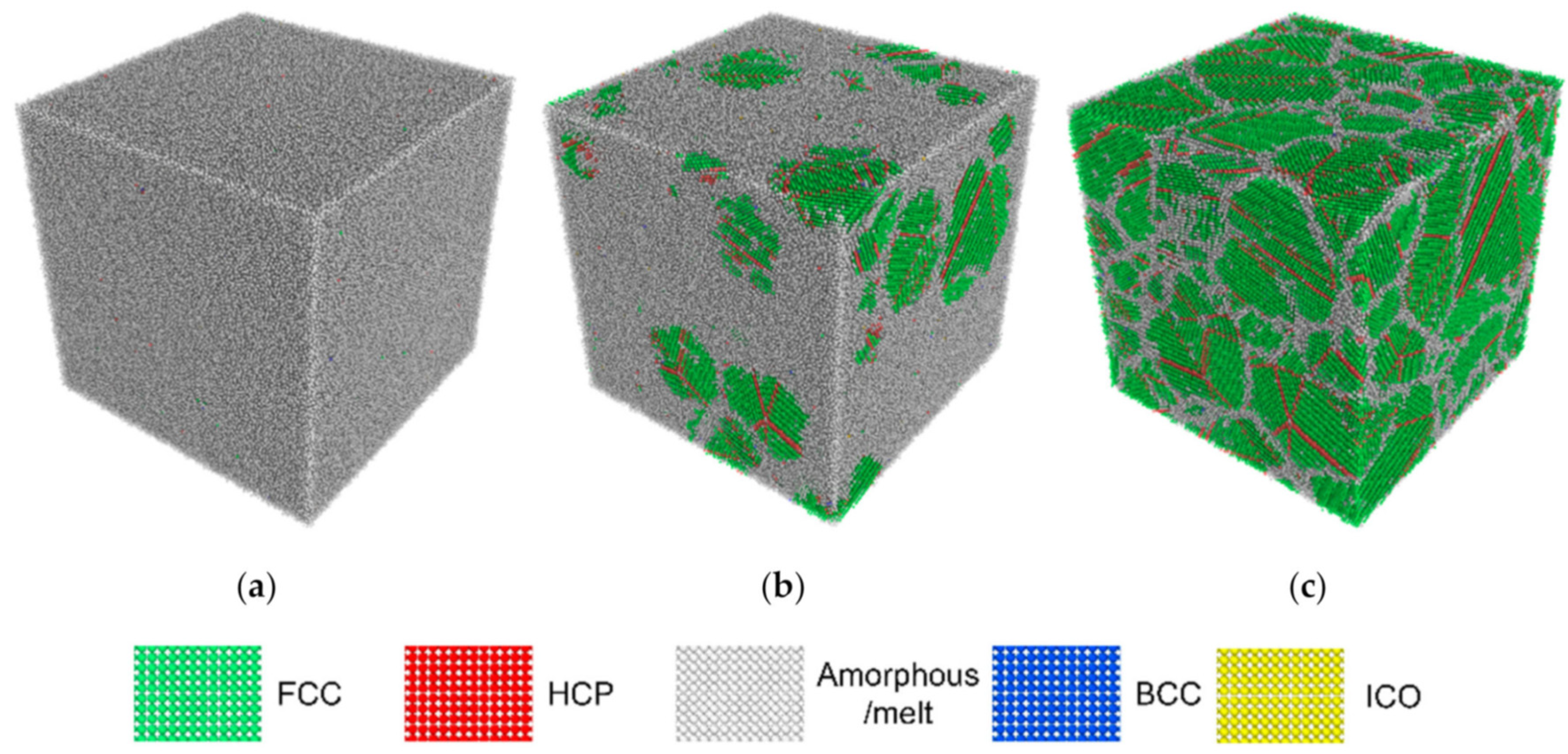
Figure 1. Molecular dynamics modelling results of pure aluminium solidification at the cooling rate 0.5 K/ps at (a) T = 579 K, (b) T = 543 K and (c) T = 507 K. Reproduced from [9], Creative Commons Attribution 4.0 International license.
Metals 13 01392 g001
Figure 2. A D2Q9 computational grid, as used in LBM modelling.
Metals 13 01392 g002
Figure 3. LBM+PF modelling results of dendritic growth in natural convection. Reproduced and adapted from [32], Creative Commons Attribution 4.0 International license.
Metals 13 01392 g003
Figure 4. LBM modelling results of the evolution of fluid coherent structures during the melt flow in a continuous casting mould at different stages: (a) asymmetry, (b) transformation, and (c) mirror image. Reproduced and adapted from [34], Creative Commons Attribution 4.0 International license.
Metals 13 01392 g004
Figure 5. LBM modelling results of the solidification structure of the melt pool of an arc weld. Reproduced with permission from [38]. Copyright 2020 John Wiley & Sons.
Metals 13 01392 g005
Figure 6. LBM modelling results of the IN718 solidification structures manufactured using the EB-PBF technique. Reproduced with permission from [42]. Copyright 2016 Elsevier Science &Technology Journals.
Metals 13 01392 g006
Figure 7. Experimental result vs. SPH modelling results of the high-pressure die casting of an automobile component. Reproduced with permission from [48]. Copyright 2006 Elsevier Inc.
Metals 13 01392 g007
Figure 8. SPH modelling results of the powder dynamics and melt pool evolution during the LB-PBF. Reproduced with permission from [62]. Copyright 2022 Springer Nature BV.
Metals 13 01392 g008
Figure 9. PFEM modelling results of the melting of the fuel assembly and dropping of corium over the plate and the clasp. Reproduced with permission from [71]. Copyright 2017 Elsevier Science & Technology Journals.
Metals 13 01392 g009
Table 1. Summary of some features of the four particle-based methods.
MethodMesh-Based or MeshlessEulerian or LagrangianTarget MaterialsSome Accompanying Model of Phase Transformation
LBMMesh-basedEulerianSolid or fluidEnthalpy, CA or PFM
SPHMeshlessLagrangianSolid or fluidEnthalpy
DEMMeshlessLagrangiangranular materialsEnthalpy
PFEMMesh-basedLagrangiansolid or fluidEnthalpy
Disclaimer/Publisher’s Note: The statements, opinions and data contained in all publications are solely those of the individual author(s) and contributor(s) and not of MDPI and/or the editor(s). MDPI and/or the editor(s) disclaim responsibility for any injury to people or property resulting from any ideas, methods, instructions or products referred to in the content.