Article

Micro End Mill Capability Improvement Due to Processing by Fast Argon Atoms and Deposition of Wear-Resistant Coating

Department of High-Efficiency Machining Technologies, Moscow State University of Technology “STANKIN”, Vadkovsky Lane 3a, 127055 Moscow, Russia
*
Author to whom correspondence should be addressed.
Metals 2023, 13(8), 1404; https://doi.org/10.3390/met13081404
Submission received: 7 July 2023 / Revised: 28 July 2023 / Accepted: 3 August 2023 / Published: 6 August 2023

Abstract

:
Micro-milling is widely used to make micro-channels in various fields. In this study, micro-milling of rectangular bronze microchannels was carried out with carbide end mills with a diameter of 1 mm, processed with fast argon atoms, and coated with anti-friction wear-resistant titanium diboride. It was shown that the removal of a 3 µm thick surface layer from a micro end mill with fast argon atoms makes it possible to reduce the cutting edge radius of the tool to 1.2 µm, which is three times lower than the minimum value of 4 µm achievable in mechanical manufacturing. The subsequent deposition of a 3 μm thick anti-friction coating results in a wear-resistant micro end mill with original geometric parameters but improved performance. The surface roughness of the machined bronze microchannel significantly decreased, and the burrs above the groove practically disappeared after micro-milling.

1. Introduction

Micro-milling is one of the most advanced microfabrication processes due to its ability to produce complex shapes from a variety of materials with strict surface quality and precision [1]. Therefore, micro molds and dies are mainly produced by micro milling. To increase the service life of micro end mills, they are subjected to the deposition of wear-resistant coatings. It was reported in [2] that hard nitride-based coatings improve the tooling performance compared to uncoated tools. The wear resistance of uncoated, DLC-coated, TiAlN-coated, TiAlN+AlCrN-coated, and TiAlN+WC/Co-coated carbide micro end mills was studied in [3] when machining an Inconel 718 superalloy. All coated tools were found to perform better than uncoated micro end mills by reducing tool wear. Among them, the AlTiN-coated tool showed the best performance among others.
In [4], the performance of a micro-end mill coated with a nanocrystalline diamond (NCD) and an uncoated micro-end mill for the micro-milling of an aluminum alloy was studied. A significant improvement in machining performance, i.e., reduction in cutting force, surface roughness, and tool adhesion with NCD coating was reported. A significant effect of diamond coating on the micro-milling of very hard ZrO2 ceramics was reported in [5]. The diamond-coated tool retained its geometry during machining and allowed the hard material to be machined. Machining with a carbide tool without coating was impossible, as it wore out very quickly and its geometry changed.
The thicker the coating, the longer its service life. However, the deposition of wear-resistant coating increases the cutting edge radius. In the case of tools with a cutting edge radius exceeding 10 µm, the coating thickness of 5 µm is quite acceptable. This is completely different in the case of a microtool with a cutting edge radius smaller than 5 μm. When micro-milling, the processing parameters are reduced to the level of several microns, and the undeformed chip thickness is comparable to the radius of the cutting edge of the micro end mill. The problems caused, such as minimum undeformed chip thickness, effective rake angle, and size effect have a significant impact on the cutting process and machining quality [6].
The size effect in metal cutting usually is understood as the nonlinear increase in specific cutting energy with the decrease of undeformed chip thickness [7]. It was found in [8] that instead of reducing the cutting force with a TiAlN-coated tool compared to an uncoated carbide tool for Ti-6Al-4V micro-milling, the cutting force increased. The reason is that the increase in the cutting edge radius due to the coating deposition increases plowing and friction and causes an increase in cutting force. It was reported in [9] that when micro-milling Ti-6Al-4V, a tool coated with cubic boron nitride CBN had a higher cutting force than an uncoated tool. Due to thin film deposition, the cutting edge radius of the micro end mill increases, which leads to various adverse size effects such as minimum chip thickness, ploughing, friction, etc. These size effects increase tool wear and surface roughness and generate higher forces. Therefore, in order to reduce both friction and size effects, it is necessary to optimize the coating thickness of the coated micro end mill.
To ensure the material removal and avoid the ploughing effect in micro milling [10], it is needed to determine the minimum undeformed chip thickness. For this purpose, the observation of the chip formation, cutting force signal, and acoustic emission signal are used. Based on the acoustic emission signal it was reported in [11] that for micro-milling of Inconel 718 with the tool cutting edge radius of 6 µm the minimum undeformed chip thickness is 1.4 µm. Observation of the signal variation of cutting force in micro-milling of aluminum alloy 6061 [12] gave the minimum undeformed chip thickness of about 0.3 rn, where rn is the cutting edge radius. It was found in [13] that the minimum chip thickness for micro-milling of the aluminum 6082-T2 is around 0.2–0.3 µm, which is about 14–21% of the tool cutting edge radius rn. It was found in [14] that in micro-milling of titanium alloy, the minimum undeformed chip thickness varies between 0.15 rn and 0.49 rn. In [15], the minimum undeformed chip thickness was determined to be 0.17 rn. It was found experimentally that the minimum undeformed chip thickness results in an unstable cutting process [16,17,18]. Due to the minimum undeformed chip thickness, the ploughing effect causes great specific cutting energy and deteriorates surface roughness.
The size effect highly dominates the material removal process increasing surface roughness and causing significant burr formation. Therefore, surface roughness and burr formation are used as an estimate when selecting micro-milling parameters [19,20]. A number of studies have been carried out to investigate surface quality and burr formation during the micro-milling process. Wang et al. [21] found that feed rate was the most dominant parameter for micro-milling a brass surface when other parameters were held constant, and surface roughness increased linearly as tool diameter and spindle speed increased. Jean et al. [22] studied the effect of parameters on surface topography and cutting forces during the micro-milling of AISI D2 steel. Large burr size and surface roughness were created at a low feed per tooth to cutting edge radius ratio. Biermann and Kanis [23] investigated the effect of reducing tool diameter and machining parameters on specific cutting forces, surface roughness, and burr formation during the micro-milling of steel.
It may be concluded from the abovementioned that wear-resistant coatings, which can appreciably improve the machining performance of carbide micro end mills, cannot sufficiently increase the service life of the tools due to the limited thickness of the coatings. For instance, it is not reasonable to deposit on micro mills with a cutting edge radius of 6 µm [11] coatings with a thickness of 3–5 µm. When, however, a 3 µm thick surface layer is removed from the end mill surface and then a 3 µm thick wear-resistant coating is deposited on it, we may obtain a tool with the same surface topography and increased service life. Changing the surface layer material of a micro end mill using a mechanical treatment seems to be quite difficult.
Therefore, in this study, end mill processing with a beam of fast argon atoms [24,25] was used to remove a surface layer of its material, and magnetron sputtering was used to deposit a wear-resistant coating [26,27]. The novelty of this study is a new approach to increasing the wear resistance of micro end mills and improving their performance by replacing the surface layer of the tool with a thickness of ~3 μm with a wear-resistant layer of the same thickness.

2. Materials and Methods

2.1. Experimental Setup

The end mills from Iscar (Israel) under catalog number 5650507 with a nominal diameter of 1 mm and length of 2 mm of the working part, as well as with a nominal chip flute angle of 30 degrees (Figure 1) were chosen as samples for experiments. The material of the end mills was solid carbide type IC08 Micrograin: monocarbide (WC-80%; Co-20%) with a carbide grain size of 0.4–0.8 μm, hardness Rockwell 84.0 HRA, and transverse rupture strength 2058 N/mm2. The work surfaces of the end mills were polished and uncoated. According to the catalog, their application areas are heat-resistant alloys, stainless steel, and aluminum.
While processing the end mill, it is needed to control its geometric parameters: the angular parameters of the cutting edge, the front, and rear corners, and the cutting edge radius (Figure 2). To control the changes in the cutting edge radius of the micro end mill, measurements were carried out using a scanning electron microscope PHENOM G2 PRO produced by PHENOM (Rotterdam, The Netherlands).
Figure 3 presents an experimental setup for sharpening cutting edges of carbide micro end mills and subsequent deposition of wear-resistant coatings. It is composed of a working vacuum chamber and a beam source of fast neutral atoms. Inside the beam source are a 40 cm diameter and 25 cm long hollow cathode and a 30 cm diameter concave grid with a surface curvature radius amounting to 40 cm. Both the cathode and the grid are made of a 1.5 mm thick titanium sheet. An anode inside the hollow cathode is connected through a high-voltage feedthrough to the positive pole of a discharge power supply. Its negative pole is connected to the positive pole of an accelerating voltage power supply and through a second feedthrough to the hollow cathode. Its negative pole is connected to the grid. The latter is connected through a resistor to the working vacuum chamber. On the grid surface are evenly distributed 7 mm diameter holes at a distance of 8 mm between their centers. Using a two-channel gas supply system, the ion-forming gas is injected into the beam source. Through the grid, it enters the working vacuum chamber and is pumped out by a turbomolecular pump through a 20 cm diameter pumping channel on the side wall of the chamber. Opposite the pumping channel, there is a 25 cm diameter door, which makes it possible to load tools and samples into the chamber. On the door there is a quartz window with a movable shutter, preventing the deposition of films. The window allows measuring the temperature of the processed end mill with an infrared pyrometer. The gas pressure in the chamber is measured by an MKS vacuum meter with a BARATRON transducer (MKSI, Andover, MA, USA) and regulated from a control panel.
A holder rotating with a speed of 60 rpm was installed in the lower part of the 50 cm diameter and 40-cm-long working vacuum chamber. The holder was surrounded by a grounded cylindrical screen and connected to the negative pole of a bias voltage power supply. An end mill was installed in the 3 mm diameter and 30-mm-deep socket of the holder, and its cutting part was at the focal point of the grid.
A 10 cm diameter magnetron target made of titanium diboride was mounted on the opposite wall of the chamber. The axis of the end mill was 10 cm away from the target. The choice of TiB2 coating with a high melting point of 3225 °C, high modulus of elasticity (≥450 GPa), and low resistivity (10–30 µΩ∙cm) is related to its good adhesion resistance, chemical stability, and high hardness when machining non-ferrous metals and high-temperature alloys, which is critical for micro-milling (Table 1).
This avoids the formation of build-ups on the cutting edge of the micro mill and thereby improves the quality of the machined surface when the tool is worn. Its outstanding properties are determined via a crystalline structure and atomic bonds. The titanium atoms in TiB2 are arranged in a hexagonal structure, with strong covalently bonded B atoms located in the gaps, which results in alternating Ti and B planes.
At the argon pressure of 0.2 Pa, turning on the discharge power supply and the accelerating voltage power supply leads to the ignition of a glow discharge and filling the hollow cathode with a plasma emitter of ions [27]. The ions are accelerated in the sheath of positive space charge between the plasma and the grid and through its holes enter the chamber. The energy of accelerated ions corresponds to the difference between the potential of the plasma emitter, which is equal to the anode potential and the potential of secondary plasma in the chamber, which is practically equal to the chamber potential. Hence, the ion energy is equal to Ei = e(Ud + U), where e is the electron charge, Ud is the discharge voltage between the anode and the hollow cathode, and U is the accelerating voltage between the hollow cathode and the chamber. At Ud = 400 V and U = 3600 V, the ion energy is equal to 4000 eV. Due to charge exchange collisions with gas atoms, the accelerated ions are converted in the chamber into fast neutral atoms with the same kinetic energy. Simultaneously, slow ions appear, the charges of which are neutralized by electrons from the chamber walls. Thus, a secondary plasma is formed. The slow ions move to the grid and the chamber walls. Their current through the resistor induces a negative voltage of 100–200 V on the grid, thus preventing electrons of the secondary plasma from entering the beam source. Taking into account that the gas density at the pressure of 0.2 Pa is equal to no = 5 × 10¹⁹ м−3 [29] and the charge exchange collision cross-section of argon ions with 4 keV energy is equal to 2 × 10⁻¹⁹ м2 [30,31], we obtain, for the mean free path of argon ions between the charge exchange collisions, λc = 1/noσc = 0.1 m. Since the distance of 0.4 m between the grid and the end mill located at the focus of the grid is four times greater, it can be assumed that all ions that hit the tool surface are already converted into fast argon atoms.
To determine the flux density of fast atoms on the end mill surface, flat titanium targets were etched. The targets made of 1 mm thick titanium sheets were fixed one after the other vertically at different distances x from the center of the grid in the absence of the holder. At a current Id = 2 A in the circuit of the hollow cathode with the surface area of Sc = 4500 cm2, the current density of ions accelerated by the grid amounts to Id/Sc = 0.44 mA/cm2. At the grid transparency of η = 0.75 and surface area of Sg = 800 cm2, the beam current of accelerated ions entering the chamber is equal to Ib = η Sg Id/Sc = 0.264 A, and the power transported by the beam amounts to Ib(Ud + U) = 0.264 × 4000 = 1056 W.
Figure 4 presents the dependance of the diameter D of the beam imprint on a flat target on its distance h to the grid center.
First, it monotonically diminishes from D = 10 cm at the distance h = 27 cm to D = 6 cm at h = 33 cm, to D = 2 cm at h = 37 cm, and then starts rising again to D = 4 cm at the distance h = 45 cm. So, high power density at the distance from the grid h~40 cm is available due to the absence of electrical charges in the beam, which usually limit the currents of electron and ion beams. In our case, the minimum beam diameter is determined only by the angular dispersion of ions that occurs when passing through the grid.

2.2. Characterization of the Samples

The cutting edges of micro end mills were controlled using a scanning electron microscope PHENOM G2 PRO produced by PHENOM (Rotterdam, The Netherlands).
The microhardness of the samples was measured using the Micro Indentation TesterMNT produced by Anton Paar Switzerland AG (Buchs, Switzerland).
For in-situ measuring of the sample temperature, an infrared pyrometer IMPAC IP 140 (LumaSense Technologies GmbH, Frankfurt am Main, Raunheim, Germany) was used.
Characterization of the coating adhesion was carried out using a Nanovea M1 Hardness and Scratch Tester produced by Nanovea INC. (Irvine, CA, USA).
Elemental analysis of substrate material was provided by a VEGA3 LMH scanning electron microscope (Tescan, Brno, Czech Republic).
The profilograms of the tool surface were obtained using the HOMMEL TESTER T8000 high-precision profilograph-profilometer produced by the company Hommelwerke GmbH (JENOPTIK Industrial Metrology Germany GmbH, Jena, Germany).
The dimensions of the burrs were measured using an Axiotech Vario optical microscope by Carl Zeiss, (Göttingen, Germany).
The roughness of the grove surface was evaluated using a Dektak XT stylus profilometer manufactured by Bruker Nano, Inc. (Billerica, MA, USA).

3. Results

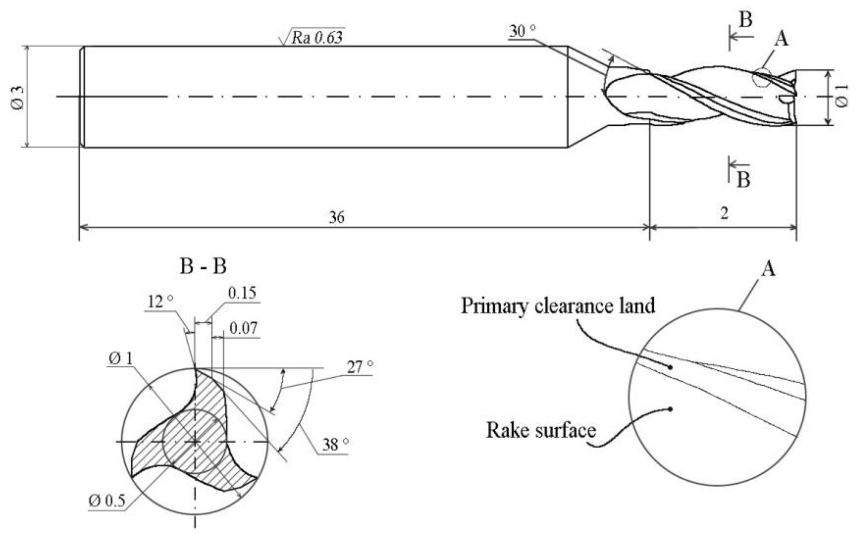
3.1. Sharpening Cutting Edges of Micro End Mills

Before processing, a micro end mill was ultrasonically cleaned of impurities. Then, its cutting edge radius was measured using a scanning electron microscope PHENOM G2 PRO. The initial cutting edge radius of a 1 mm diameter tungsten carbide micro end mill amounted to 4.2 µm.
After the micro end mill was installed in the 3 mm diameter and 30 mm deep socket of the holder (Figure 3), the chamber was evacuated to a residual gas pressure of 0.001 Pa and filled with argon at a pressure of 0.2 Pa. When the power supplies were switched on, glow discharge was ignited and ions accelerated from the discharge plasma started their movement through the grid to the micro end mill. At the discharge current of 2 A in the hollow cathode circuit and the accelerating voltage of 3600 V between the cathode and the chamber, the rotating end mill was treated for half an hour by argon atoms with an energy of 4000 eV. When processing the end mill, the temperature of its shank, as measured by an infared pyrometer, was 750 °C. Through the window, during the temperature measurement, it was visible that the micro end mill was glowing red. This temperature is unacceptable for many tool materials, but is normal for tungsten carbide.
When the treated end mill was removed from the 3 mm diameter socket of the holder, a step between the shank surface masked with the holder and the shank surface etched by fast argon atoms appeared. According to the HOMMEL TESTER T8000 high-precision profilometer, the step height of 1.2 µm was measured. It means that the tool etching rate amounts to 2.4 µm/h. Measurements using a scanning electron microscope, PHENOM G2 PRO, revealed a decrease in the cutting edge radius to 3 µm, i.e., by 1.2 µm, which is equal to the thickness of the surface layer removed from the shank.
Another micro end mill with an initial cutting edge radius of 4.3 µm was treated for 1.5 h at the same argon pressure of 0.2 Pa, a discharge current of 2 A, and an accelerating voltage of 3600 V. In this case, the thickness of the surface layer removed from the end mill shank was equal to 3.5 µm and the cutting edge radius diminished from 4.3 µm (Figure 5a) to 1.5 µm (Figure 5b), i.e., by 2.8 µm, which is less than the thickness of the surface layer removed from the shank.
After a third tungsten carbide micro end mill with an initial cutting edge radius of 4.2 µm was treated for 2 h at the same argon pressure of 0.2 Pa, a discharge current of 2 A, and an accelerating voltage of 3600 V, the thickness of the surface layer removed from the end mill shank was equal to 5 µm and the cutting edge radius diminished from 4.2 µm (Figure 5a) to 1.2 µm, i.e., by 3 µm, which is less than the thickness of the removed surface layer. Presumably, the low limit of the cutting edge radius is associated with the carbide grain size of 0.4–0.8 μm, which cannot exceed the cutting edge radius. This means that it makes no sense to treat end mills for more than 1.5 h since the radius of the cutting edge remains constant at ~1.5 µm.

3.2. Deposition of Wear-Resistant Coatings

Immediately after processing the fourth micro end mill for 1.5 h at the same argon pressure of 0.2 Pa, a discharge current of 2 A, and an accelerating voltage of 3600 V, the magnetron power supply was switched on with a current in the magnetron target circuit of 4 A and the target voltage of 430 V. Simultaneously, the bias voltage power supply was switched on and during the 1 h long deposition, a negative bias of −150 V was applied to the end mill for promotion of crystallinity. Using an infrared pyrometer, it was found that after turning off the beam source, the temperature of the end mill decreased to 450 °C and remained at this level until the end of processing.
After the coating deposition, the cutting edge radius of the end mill was equal to 4 µm and a 1 µm high step between the masked and open surfaces of the end mill shank showed a decrease in the shank diameter after the processing. Taking into account that due to 1.5 h long etching with fast argon atoms, a 3.5-µm-thick surface layer being removed from the end mill shank, and the cutting edge radius diminishing to 1.5 µm, we may suppose that due to subsequent 1 h long deposition of a 2.5-µm-thick coating, the cutting edge radius increased from 1.5 µm to 4 µm and the height of the shank step decreased from 3.5 µm to 1 µm.
Thus, the combined modification of micro end mills, which comprises etching the tool surface with fast argon atoms and subsequent deposition of wear-resistant coating, allows an increase in the tool service life without increasing the cutting edge radius.

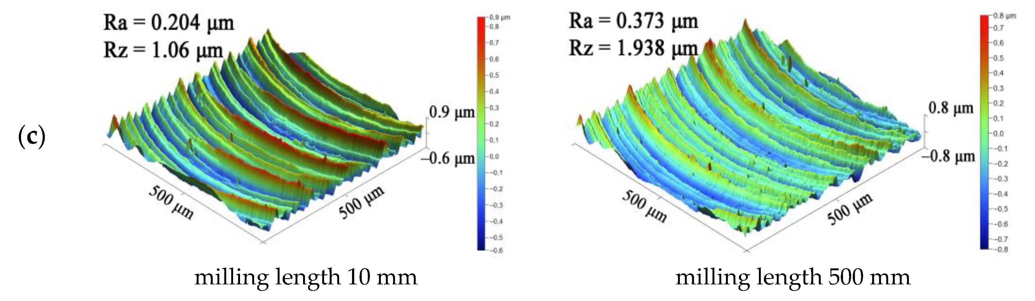
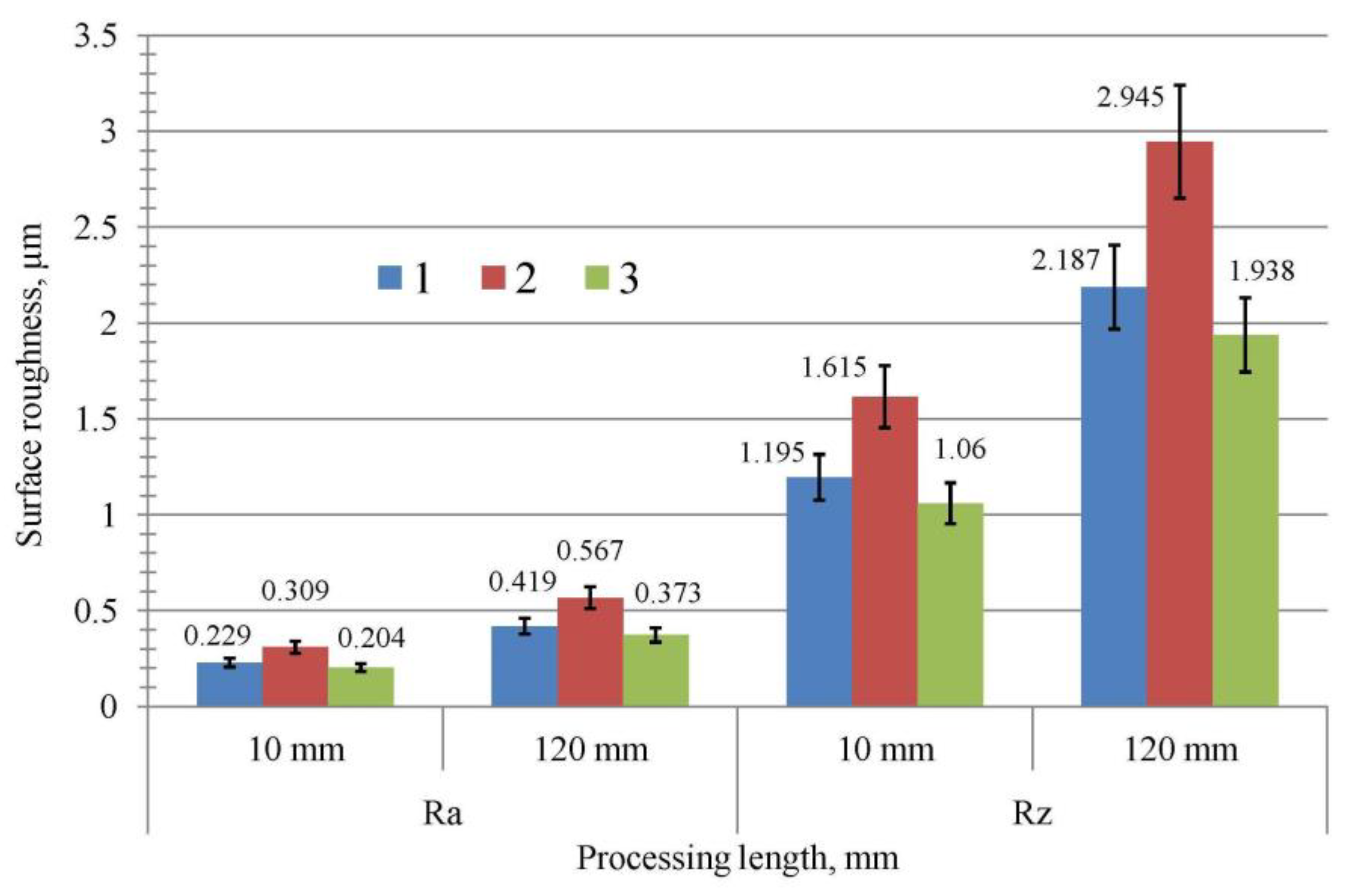
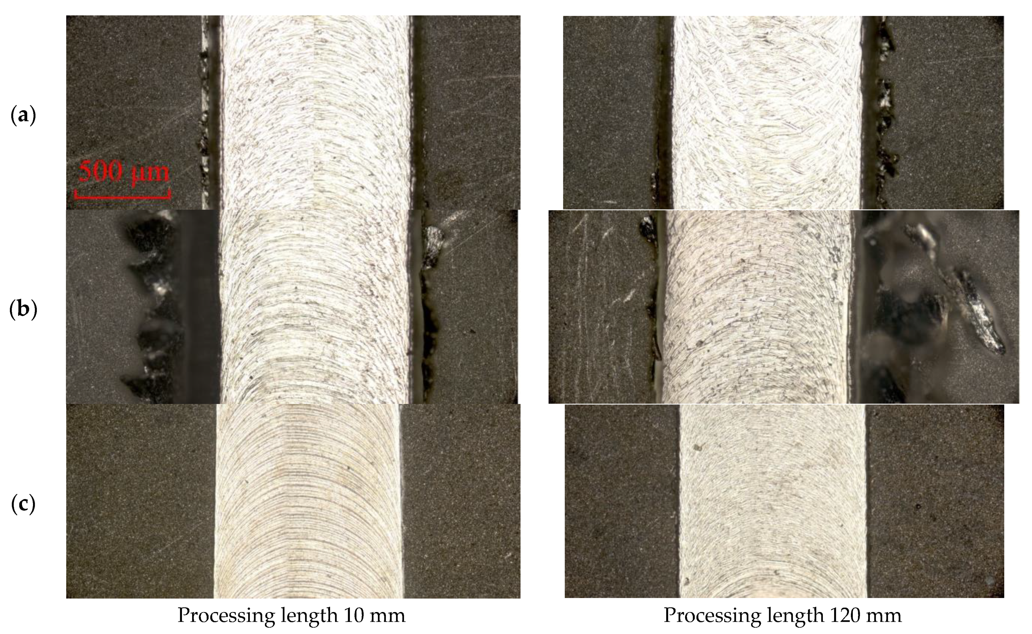
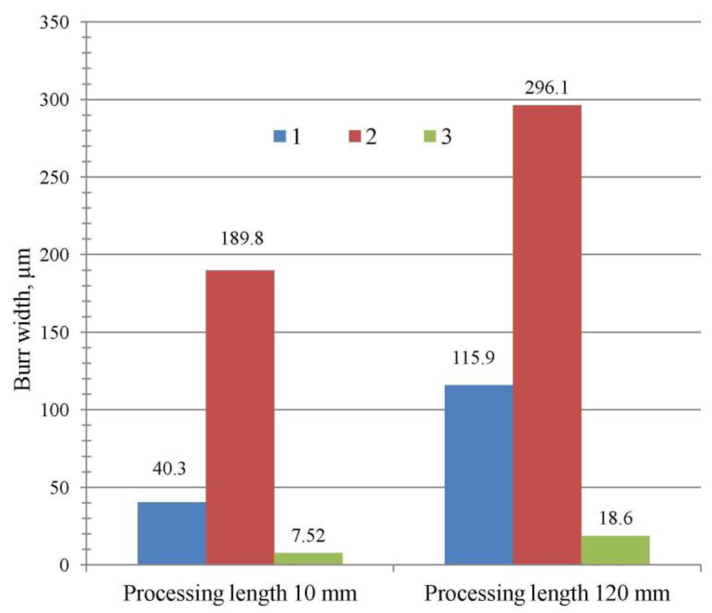
3.3. Performance of Modified Micro End Mills

Wear resistance testing of modified carbide micro end mills was carried out on a CNC drilling and milling machine Bungard CCD/ATC by Bungard (Windeck, Germany) with a positioning accuracy of the pneumatic drive of ±2.5 µm with a high-speed spindle KAVO 150 W, 25,000–60,000 rpm (Figure 6).
The micro end mills were used to process the grooves for supplying cooling liquid on plates made of bronze CuAl8Fe3 (Figure 7). Taking into account the criteria proposed by Sahu et al. [1] for minimum undeformed chip thickness, all experiments were carried out at a spindle speed of 50,000 rpm; axial depth of cut 100 microns; and feed rate 150 mm/min. To analyze tool wear and its effect on other machinability parameters, the machining length was 500 mm.
The surface roughness value (Ra and Rz) of the machined surface was measured with a Dektak XT stylus profilometer at two different locations, and the average value was taken for analysis.
In addition, the dimensions of the burrs were measured from the image obtained using an Axiotech Vario optical microscope by Carl Zeiss (Göttingen, Germany). The burr width was measured at two different milling locations and the average value was taken for analysis.
When installing a tool in a collet tool holder, the amount of runout usually changes. To maintain a constant runout value for all types of tools, the length of the protrusion was kept constant, i.e., 15 mm, while the tool was being installed in the holder assembly, and the tool remained intact during the tightening of the collet.
The wear on the flank face was taken as the failure criterion, the maximum value of which is 150 µm. If this value is exceeded, the cutting conditions of the micro end mill and the quality of the machined surface are significantly worsened, which leads to the rejection of the product. Flank wear was measured using a Phenom G2 PRO scanning electron microscope (SEM).

3.4. Influence of Combined Modification on Wear Resistance of Carbide Micro End Mills

To assess the effectiveness of combined micro end mill modification with a fast atom beam and subsequent deposition of TiB2 coating, we measured the surface roughness of the grooves obtained after processing with an initial micro end mill (not processed), a micro end mill with TiB2 coating, and a micro end mill subjected to combined modification: etching with fast argon atoms and deposition of a TiB2 coating. The three-dimensional topography of the groove surface is shown in Figure 8.
The corresponding surface roughness values Ra and Rz obtained by averaging the grove roughness values for a fresh tool (milling length 10 mm) and a worn tool (milling length 500 mm) are shown in Figure 9. It shows that the surface roughness of the grove machined with a micro end mill after combined modification is lower than that of the groves machined with micro and mills with TiB2 coating and without processing. This is due to a decrease in the cutting edge radius of the micro end mill after sharpening with fast argon atoms and an improvement of its tribological characteristics due to the deposition of the low-friction TiB2 coating.
When using an unsharpened end mill with a 2.5 µm thick TiB2 coating, due to improper chip formation and an additional increase in friction, the surface roughness of the grooves increased. In addition, with an increase in the processing length, the micro end mill was worn out. Therefore, Figure 9 reveals an increase in the surface roughness of a groove machined with a worn micro end mill. It also shows that the value of the surface roughness of the groove machined with a worn uncoated tool is maximum compared to tools with TiB2 coating and with combined modification. This is due to the lower tribological performance of the uncoated tungsten carbide compared to the TiB2-coated surface and the high wear of the uncoated tool. From the overall analysis of surface roughness, it can be seen that by reducing the effects of friction and size, the micro end mill with combined modification showed the best performance among TiB2-coated and uncoated micro mills.
Figure 10 shows images of burrs formed by micro end mills without processing, coated with TiB2, and subjected to combined modification.
During micro-milling, due to the incomplete removal of the material being machined by the micro end mill in the form of chips, a certain amount of material remains on the side wall of the groove in the form of so-called burrs. The amount of burr depends on the machining parameters, cutting tool geometry, and cutting conditions. Clearly, a low-friction hard coating on a cutting tool is indeed beneficial in reducing burr formation, facilitating chip formation and resisting tool wear.
Figure 11 shows that the burr size of the micro end mills subjected to combined processing is much smaller due to the low friction and wear resistance of the TiB2 coating. Larger burrs were detected for a micro end mill with a 2.5 µm thick TiB2 coating. This is due to the increase in the cutting edge radius of the micro end mill, which prevents proper chip formation.
In addition, the size of the burrs increased for all types of micro mills with increasing cutting length. Due to wear, the edges of the micro end mill lost their sharpness, which led to an increase in the cutting edge radius. Consequently, this caused more friction and more burrs when micro-milling with worn micro tools.
Durability testing of the modified micro end mill was carried out in comparison with TiB2-coated micro end mills and micro end mills without processing. The wear resistance of micro end mills was evaluated by the wear of the flank face (Figure 12). For the criterion of micro mill failure in the processing, the limiting wear of 150 microns on the flank face was taken.
As shown in Figure 12, the wear of the micro end mill without modification reached the limit value (150 µm) at a milling length of 148 mm (curve 1). The wear of a micro end mill with a 2.5 µm thick TiB2 coating at the same milling length of 148 mm amounts to 75 µm (curve 2), and for a micro end mill with a 2.5 µm thick TiB2 coating deposited after removal of a 3.5 µm thick surface layer, it amounts to 55 µm (curve 3).
Thus, the wear-resistant coating increases the service life of micro end mills by 2 times, and the combined modification by 2.7 times.

4. Discussion

To decrease the cutting edge radius of micro milling tools, an immersed tumbling process was used in [32]. The authors reported that “micro cutters were manufactured with a cutting edge radius of 4.0 μm, which is lower than the value of 10 μm available with traditional grinding methods”. After that, the value of 4.0 μm was supposed to be the minimum achievable cutting edge radius of carbide micro end mills. In the present study, we showed that processing with fast argon atoms makes it possible to reduce the cutting edge radius by three times from 4.0 μm to 1.2 μm. Additionally, it was found that a further decrease in the cutting edge radius is impossible because it cannot be less than the carbide grain size of 0.4–0.8 µm.
The results obtained confirmed the efficiency of sharpening micro end mills with fast argon atoms. The minimum radius of the cutting edge of carbide micro end mills with a diameter of 1 mm reached 1.2 μm after processing a rotating micro end mill for 1.5 h. This is several times less than the cutting edge radius available in the mechanical manufacture of tools [32].
A further increase in the processing time was accompanied by a proportional increase in the thickness of the surface layer removed from the tool shank. However, no change in the radius of the cutting edge was observed. No doubt, the fast argon atoms continued sputtering the cutting edges of the micro end mill without sharpening them. This can be explained by the carbide grain size of 0.4–0.8 μm, which limits a further decrease in the cutting edge radius.
However, sharpening micro end mills with fast argon atoms made it possible to reduce the cutting edge radius by 2.5 µm, and then redeposit a 2.5 µm thick TiB2 wear-resistant coating. This change in surface layer material allowed us to obtain a wear-resistant micro end mill with low friction and an unchanged geometry that avoids size effects.
Comparison of the micro end mills not subjected to processing with those subjected to deposition of wear-resistant titanium diboride coatings and combined processing with fast argon atoms and subsequent deposition of wear-resistant coatings showed the priority of the latter group. The deposition of low-friction wear-resistant titanium diboride coatings should increase the service life of micro end mills and improve the surface quality of processed products. However, the deposition of a 2.5 μm thick TiB2 coating on a micro end mill with a cutting edge radius of 4.2 μm resulted, quite the contrary, in an increase in the burr sizes and the surface roughness of processed products.
When a 2.5 μm thick TiB2 coating was deposited on a micro end mill with a cutting edge radius of 1.2 μm, the surface roughness of the processed workpiece decreased and the burrs above the groove after micro-milling practically disappeared.
Thus, the combined processing of carbide micro end mills substantially improved the capability and quality of processed products. Future research should be directed to other tool materials, including dielectrics, and finding a way to a further decrease the cutting edge radius of the tools.

5. Conclusions

1. A uniform etching of the micro end mills surface with fast argon atoms makes it possible to obtain cutting edge radii much smaller than in mechanical grinding. The lower limit of the cutting edge radius of carbide micro end mills is associated with a carbide grain size of 0.4–0.8 µm;
2. An appreciable decrease in the cutting edge radius of the micro end mill due to processing with fast argon atoms allowed the deposition of 3 µm thick titanium diboride coatings without reaching the threshold of size effect, thus substantially improving the machining capability;
3. The wear-resistant titanium diboride coating deposited after sharpening the micro end mill with fast argon atoms increased the mill’s service life by 2.7 times.

Author Contributions

Conceptualization, A.M., M.V. and S.G.; methodology, A.M. and M.V.; software, E.M.; validation, A.M., M.V. and Y.M.; formal analysis, Y.M.; investigation, E.M. and Y.M.; resources, E.M. and Y.M.; data curation, M.V. and Y.M.; writing—original draft preparation, A.M. and M.V.; writing—review and editing, A.M. and S.G.; visualization, E.M.; supervision, A.M. and S.G.; project administration, M.V.; funding acquisition, S.G. All authors have read and agreed to the published version of the manuscript.

Funding

This work is funded by the state assignment of the Ministry of Science and Higher Education of the Russian Federation, project No FSFS-2021-0006.

Data Availability Statement

Data sharing is not applicable to this article.

Acknowledgments

The study was carried out using the equipment of the Center of Collective Use of MSUT “STANKIN”, supported by the Ministry of Higher Education of the Russian Federation (project No. 075-15-2021-695 from 26 July 2021, unique identifier RF 2296.61321X0013).

Conflicts of Interest

The authors declare no conflict of interest.

References

  1. Sahoo, P.; Patra, K. Cumulative reduction of friction and size effects in micro milling through proper selection of coating thickness of TiAlN coated tool. J. Manuf. Process. 2021, 67, 635–654. [Google Scholar] [CrossRef]
  2. Balázs, B.Z.; Takács, M. A comparative analysis of characteristics of cutting forces at micro-milling of hardened steels. IOP Conf. Ser. Mater. Sci. Eng. 2020, 903, 012056. [Google Scholar] [CrossRef]
  3. Bohley, M.; Reichenbach, I.G.; Kieren-Ehses, S.; Heberger, L.; Arrabiyeh, P.A.; Merz, R.; Böhme, L.; Hering, J.; Kirsch, B.; Kopnarski, M.; et al. Coating of Ultra-Small Micro End Mills: Analysis of Performance and Suitability of Eight Different Hard-Coatings. J. Manuf. Mater. Process. 2018, 2, 22. [Google Scholar] [CrossRef] [Green Version]
  4. Alhadeff, L.; Marshall, M. Applying experimental micro-tool wear measurement techniques to industrial environments. Proc. Inst. Mech. Eng. Part B J. Eng. Manuf. 2021, 235, 1588–1601. [Google Scholar] [CrossRef]
  5. Srinivas, M.S.; Sangeeth, P.; Venkaiah, N.; Sankar, M.R. State of the art on tool wear characterization in micro-milling. Mater. Today Proc. 2023; in press. [Google Scholar] [CrossRef]
  6. Saha, S.; Kumar, A.S.; Malayath, G.; Deb, S.; Bandyopadhyay, P.P. Energy balance model to predict the critical edge radius for adhesion formation with tool wear during micro-milling. J. Manuf. Process. 2023, 93, 219–238. [Google Scholar] [CrossRef]
  7. Sorgato, M.; Bertolini, R.; Bruschi, S. On the correlation between surface quality and tool wear in micro–milling of pure copper. J. Manuf. Process. 2020, 50, 547–560. [Google Scholar] [CrossRef]
  8. Krishnan, N.A.; Mathew, J. Studies on wear behaviour of AlTiN-coated WC tool and machined surface quality in micro end milling of Inconel 718. Int. J. Adv. Manuf. Technol. 2020, 110, 291–307. [Google Scholar] [CrossRef]
  9. Chen, N.; Li, H.N.; Wu, J.; Li, Z.; Li, L.; Liu, G.; He, N. Advances in micro milling: From tool fabrication to process outcomes. Int. J. Mach. Tools Manuf. 2021, 160, 103670. [Google Scholar] [CrossRef]
  10. Sahoo, P.; Patra, K.; Szalay, T.; Dyakonov, A. Determination of minimum uncut chip thickness and size effects in micro-milling of P-20 die steel using surface quality and process signal parameters. Int. J. Adv. Manuf. Technol. 2020, 106, 4675–4691. [Google Scholar] [CrossRef]
  11. Sahoo, P.; Patra, K.; Pimenov, D.Y. Enhancement of micro milling performance by abrasion-resistant coated tools with optimized thin-film thickness: Analytical and experimental characterization. Int. J. Adv. Manuf. Technol. 2022, 120, 2993–3015. [Google Scholar] [CrossRef]
  12. Liu, T.; Liu, Y.; Zhang, K. An improved cutting force model in micro-milling considering the comprehensive effect of tool runout, size effect, and tool wear. Int. J. Adv. Manuf. Technol. 2022, 120, 659–668. [Google Scholar] [CrossRef]
  13. Chen, Y.; Wang, T.; Zhang, G. Research on Parameter Optimization of Micro-Milling Al7075 Based on Edge-Size-Effect. Micromachines 2020, 11, 197. [Google Scholar] [CrossRef] [Green Version]
  14. Sahoo, P.; Pratap, T.; Patra, K. Prediction of Cutting Forces in Micro-Milling of P-20 Steel by TiAlN-Coated WC Tool: An Analytical Approach. In Advances in Simulation, Product Design and Development; Lecture Notes on Multidisciplinary Industrial Engineering; Shunmugam, M., Kanthababu, M., Eds.; Springer: Singapore, 2020. [Google Scholar] [CrossRef]
  15. Wu, X.; Liu, L.; Du, M.; Shen, J.; Jiang, F.; Li, Y.; Lin, Y. Experimental study on the minimum undeformed chip thickness based on effective rake angle in micro milling. Micromachines 2020, 11, 924. [Google Scholar] [CrossRef]
  16. Grigoriev, S.; Vereschaka, A.; Milovich, F.; Tabakov, V.; Sitnikov, N.; Andreev, N.; Sviridova, T.; Bublikov, J. Investigation of multicomponent nanolayer coatings based on nitrides of Cr, Mo, Zr, Nb, and Al. Surf. Coat. Technol. 2020, 401, 126258. [Google Scholar] [CrossRef]
  17. Vereschaka, A.; Grigoriev, S.; Tabakov, V.; Migranov, M.; Sitnikov, N.; Milovich, F.; Andreev, N. Influence of the Nanostructure of Ti-TiN-(Ti,Al,Cr)N Multilayer Composite Coating on Tribological Properties and Cutting Tool Life. Tribol. Int. 2020, 150, 106388. [Google Scholar] [CrossRef]
  18. Grigoriev, S.; Vereschaka, A.; Zelenkov, V.; Sitnikov, N.; Bublikov, J.; Milovich, F.; Andreev, N.; Mustafaev, E. Specific features of the structure and properties of arc-PVD coatings depending on the spatial arrangement of the sample in the chamber. Vacuum 2022, 200, 111047. [Google Scholar] [CrossRef]
  19. Chen, L.; Deng, D.; Pi, G.; Huang, X.; Zhou, W. Burr formation and surface roughness characteristics in micro-milling of microchannels. Int. J. Adv. Manuf. Technol. 2020, 111, 1277–1290. [Google Scholar] [CrossRef]
  20. Han, J.; Hao, X.; Li, L.; Liu, L.; Chen, N.; Zhao, G.; He, N. Investigation on surface quality and burr generation of high aspect ratio (HAR) micro-milled grooves. J. Manuf. Process. 2020, 52, 35–43. [Google Scholar] [CrossRef]
  21. Wang, T.; Wu, X.; Zhang, G.; Chen, Y.; Xu, B.; Ruan, S. Study on surface roughness and top burr of micro-milled Zr-based bulk metallic glass in shear dominant zone. Int. J. Adv. Manuf. Technol. 2020, 107, 4287–4299. [Google Scholar] [CrossRef]
  22. Deng, D.; Zhang, Z.; Wan, W.; Ma, Q.; Sun, J. Investigation on burr formation characteristics in micro milling of Ω-shaped reentrant microchannels. J. Manuf. Process. 2022, 80, 754–764. [Google Scholar]
  23. Muhammad, A.; Kumar Gupta, M.; Mikołajczyk, T.; Pimenov, D.Y.; Giasin, K. Effect of tool coating and cutting parameters on surface roughness and burr formation during micromilling of inconel 718. Metals 2021, 11, 167. [Google Scholar] [CrossRef]
  24. Grigoriev, S.; Melnik, Y.; Metel, A. Broad fast neutral molecule beam sources for industrial-scale beam-assisted deposition. Surf. Coat. Technol. 2002, 156, 44–49. [Google Scholar] [CrossRef]
  25. Metel, A.; Bolbukov, V.; Volosova, M.; Grigoriev, S.; Melnik, Y. Source of metal atoms and fast gas molecules for coating deposition on complex shaped dielectric products. Surf. Coat. Technol. 2013, 225, 34–39. [Google Scholar] [CrossRef]
  26. Vereschaka, A.; Grigoriev, S.; Milovich, F.; Sitnikov, N.; Migranov, M.; Andreev, N.; Bublikov, J.; Sotova, C. Investigation of tribological and functional properties of Cr,Mo-(Cr,Mo)N-(Cr,Mo,Al)N multilayer composite coating. Tribol. Int. 2021, 155, 106804. [Google Scholar] [CrossRef]
  27. Vereschaka, A.; Volosova, M.; Chigarev, A.; Sitnikov, N.; Ashmarin, A.; Sotova, C.; Bublikov, J.; Lytkin, D. Influence of the Thickness of a Nanolayer Composite Coating on Values of Residual Stress and the Nature of Coating Wear. Coatings 2020, 10, 63. [Google Scholar] [CrossRef] [Green Version]
  28. Grigoriev, S.; Volosova, M.; Mosyanov, M.; Fedorov, S. The Study of Radius End Mills with TiB2 Coating When Milling a Nickel Alloy. Materials 2023, 16, 2535. [Google Scholar] [CrossRef]
  29. McDaniel, E.W. Collision Phenomena in Ionized Gases; Willey: New York, NY, USA, 1964. [Google Scholar]
  30. Phelps, A.V. Cross sections and swarm coefficients for nitrogen ions and neutrals in N2 and argon ions and neutrals in Ar for energies from 0.1 eV to 10 keV. J. Phys. Chem. Ref. Data 1991, 20, 557–573. [Google Scholar] [CrossRef]
  31. Phelps, A.V.; Greene, C.H.; Burke, J.P. Collision cross sections for argon atoms with argon atoms for energies from 0.01 eV to 10 keV. J. Phys. B At. Mol. Opt. Phys. 2000, 33, 2965–2981. [Google Scholar] [CrossRef]
  32. Uhlmann, E.; Oberschmidt, D.; Kuche, Y.; Löwenstein, A. Cutting Edge Preparation of Micro Milling Tools. Procedia CIRP 2014, 14, 349–354. [Google Scholar] [CrossRef]
Figure 1. A 1 mm diameter end mill with a 30-degree angle of the chip groove inclination.
Metals 13 01404 g001
Figure 2. Main geometrical parameters of a solid carbide micro end mill. A is a megascopic image of the cutting edge, an B is a cross-section of the end mill.
Metals 13 01404 g002
Figure 3. Experimental setup for combined processing of micro end mills.
Metals 13 01404 g003
Figure 4. Diameter D of the beam imprint on the target versus distance h to the grid.
Metals 13 01404 g004
Figure 5. SEM images of the end mill cutting edges before processing (a), after processing with fast atoms (b), and after processing with fast atoms and deposition of TiB2 (c).
Metals 13 01404 g005
Figure 6. Photo of CNC drilling-milling machine “Bungard CCD/ATC”.
Metals 13 01404 g006
Figure 7. Scheme of micro-milling a groove on a 50 mm diameter bronze substrate.
Metals 13 01404 g007
Figure 8. Profilograms of the groove surface after micro-milling (a) with an unprocessed micro end mill; (b) with a micro end mill coated with TiB2; (c) and with a micro end mill etched by fast argon atoms and then coated with TiB2.
Metals 13 01404 g008aMetals 13 01404 g008b
Figure 9. Diagram of the groove surface roughness after micro-milling with a non-processed micro end mill (1); a micro end mill coated with TiB2 (2); and a micro end mill after combined modification (3).
Metals 13 01404 g009
Figure 10. The dimensions of the burrs above the groove after micro-milling (the scale is the same for all images) with a micro end mill without processing (a); with a micro end mill with TiB2 coating (b); and with a micro end mill after combined modification (c).
Metals 13 01404 g010
Figure 11. Diagram of burr size after micro-milling with a non-processed micro end mill (1); a micro end mill with a 3 µm thick TiB2 coating (2); and a micro end mill after combined modification (3).
Metals 13 01404 g011
Figure 12. Dependences of wear along the flank face of micro end mills with a diameter of 1 mm on the processing length when milling a groove on a bronze substrate. The dashed red line shows the limiting wear of 150 microns on the flank face, three other full lines—dependences of wear along the flank face of micro end mills on the processing length. The vertical line segments demonstrate statistical dispersions of the results each measurement being repeated three times.
Metals 13 01404 g012
Table 1. Main parameters of tungsten carbide and titanium diboride [28].
MaterialMicrohardness, GPaFriction Coefficient at 20 °CFriction Coefficient at 800 °CThermal
Stability, °C
WC15 ± 0.30.651.1900
TiB229 ± 1.50.380.66950
Disclaimer/Publisher’s Note: The statements, opinions and data contained in all publications are solely those of the individual author(s) and contributor(s) and not of MDPI and/or the editor(s). MDPI and/or the editor(s) disclaim responsibility for any injury to people or property resulting from any ideas, methods, instructions or products referred to in the content.

