Article

On the Control of Elemental Composition, Macro-, and Microstructure of Directionally Solidified Additive Products from Nickel-Based Alloy

Institute of Strength Physics and Materials Science of Siberian Branch Russian Academy of Sciences, pr. Akademicheskii 2/4, Tomsk 634055, Russia
*
Author to whom correspondence should be addressed.
Metals 2023, 13(8), 1457; https://doi.org/10.3390/met13081457
Submission received: 29 June 2023 / Revised: 9 August 2023 / Accepted: 11 August 2023 / Published: 13 August 2023

Abstract

:
The present work establishes the influence of heat input and methods of heat removal at the wire-feed electron beam additive manufacturing (EBAM) process on the structure of an additive product made of a nickel-based alloy. The following printing approaches are considered: changes in heat input, 3D printing strategy, and heat removal conditions due to (1) heating of the substrate, (2) partial suppression of radiative heat dissipation, and (3) thermal insulation of the substrate. It is shown that epitaxial growth of dendrites occurs in each case. However, in the case of an increase in speed and a change in the 3D printing strategy, the directed dendritic growth is interrupted. Preheating of the substrate and subsequent maintenance of the temperature reached during the EBAM process, as well as partial suppression of the radiative component of heat removal, allow to obtain the most uniform directional structure.

1. Introduction

Nickel-based alloys with a directionally solidified structure containing rhenium in the amount of 3–4 wt.% belong to the second generation of superalloys [1,2]. These superalloys were developed to improve the service life of the hot path parts of turbojet engines for transportation and power plants, and they are still applicable in these fields [3]. The heat resistant properties of such alloys are achieved by a combination of disperse, intermetallic, and solid solution hardening. Dispersed hardening is realized by nanoscale and/or submicrocrystalline precipitates of intermetallic compound Ni3Al (where aluminum atoms can be replaced by titanium, tantalum, and niobium) and precipitates of carbide phases such as MC, M6C (where M: W, Ti, Cr, Nb, Ta, Mo). The intermetallic compound Ni3Al (commonly known as γ′-phase) also provides intermetallic hardening. Solid-state hardening of the matrix γ phase is provided by W, Ti, Cr, Ta, Co, and Re.
Increased high-temperature creep of superalloys with a directional structure originates in minimization of the number of boundaries of structural elements perpendicular to the direction of operational stress [4]. It is also caused by differences in crystal lattice parameters of the γ′- and γ-phase due to the microsegregation of chemical elements [5].
In superalloys rhenium plays a special role. Rhenium segregates into the γ matrix and prevents γ′-phase coalescence [2]. However, the presence of inhomogeneities in melt can lead to the nucleation of brittle topologically close packed phases during crystallization. Heat resistant alloys containing rhenium are usually produced by directed solidification techniques: Bridgman–Stockbarger, liquid metal cooling, and gas cooling casting. Although these technologies are conventional, they lead to the formation of a heterogenic structure in the height of the cast product, which is associated with the gradual removal of the cooled plate (from which the crystallization process begins) from the heating zone, resulting in changes in the value of the temperature gradient [6]. In addition, casting molds have a complex geometry, which can also cause inhomogeneities in the morphology and size of the crystallizing structure, as well as in the distribution of chemical elements [7].
Additive manufacturing is a promising method for producing metal products with a directed structure [8]. This approach consists of forming the product layer-by-layer by the selective melting of powdered raw material or by direct filament feeding into a molten bath formed by an electron beam, laser beam, or electric arc. Additive manufacturing eliminates the need to use casting molds for each product, which increases production speed [9,10,11,12]. Among the many approaches to the additive manufacturing of products, wire electron beam additive manufacturing (EBAM) is worth highlighting [13]. In this method, the manufacturing process takes place in a vacuum, which avoids contamination, and the control of the electron beam sweep allows the adjustment of the heat and mass transfer processes accurately. It should be noted that wire-feed EBAM has the highest productivity compared to other additive methods that use raw materials in the form of dispersed powders [14]. In addition, dispersed powder materials are significantly more expensive (in some cases by an order of magnitude) than similar materials in the form of a wire or a rod [15].
The analysis of literature data clearly shows that casting technologies of nickel-base alloy products with directional solidification have some technological disadvantages. Moreover, to ensure the directional structure of the material of such products, a significant complication of the traditional casting technology is required. At the same time, additive technologies in general and EBAM in particular allow the formation of products with directional structure if the successful combination of technological parameters is applied [8].
The present study reveals the peculiarities of additive products of a simplified shape made of superalloy ZhS32 as a response to changes in heat input [16] and heat dissipation from the melt bath in the EBAM process, including the general appearance of the products and macro-, microstructure, and the elemental composition of the material of such products.

2. Materials and Methods

As a result of a series of preliminary experiments, it was found that the main technological parameters of wire-feed electron beam additive manufacturing are the accelerating voltage (U, kV), electron beam current (I, mA), and work table movement speed (v, mm/min), which determine the heat input (E, kJ/mm) [16] and are related by the equation [17,18]:
E = 60 × U × I 1000 × v
The formation of additive products with satisfactory adherence to the specified shape and without macro defects is ensured by an exponential decrease in heat input as the height of the additive product increases [19,20].
In the present work, additive products were formed by EBAM using rods of the superalloy ZhS32 (an analogue of CMSX-4 superalloy [21,22]). The additive products had a simplified shape of vertical walls. Several schemes of heat input and heat removal from the melt bath in the process of EBAM were used during their formation. Six walls were formed with the following technological features:
I—Adding a gap between the substrate and the worktable, see Figure 1a, to reduce the thermally conductive component of heat transfer through the substrate to the worktable. An additive product formed with similar values of key process parameters but without substrate insulation was labeled “0”. A recent paper [20] presents all aspects of the formation and features of the macro-, micro-, and fine structure of this additive product.
II—Reducing the initial beam current Ii(II) to 4/5 of the value of the initial beam current Ii(I) of the additive process labeled “I”, see Figure 1b and Table 1, in order to decrease heat input.
III—Doubling the 3D printing speed (worktable movement rate v) relative to the printing speed in the additive process labeled “I” and in all other additive processes, see Figure 1c and Table 1, also to decrease heat input.
IV—Multi-directional 3D printing with perpendicular bar feed relative to the print path, see Figure 1d.
V—Preheating of the substrate to 400 °C and maintaining this temperature throughout the additive process using a belt heater, combined with decreasing heat input by reducing the initial beam current Ii(V) to 4/5 of the initial beam current Ii(I) of the additive process labeled “I”, see Figure 1e and Table 1.
VI—Partial suppression of the radiation component of heat dissipation by installing an austenitic steel reflective curtain around the additive formed product combined with a reduction heat input by reducing the initial beam current Ii(VI) to 23 mA, see Figure 1g and Table 1.
Table 1 shows the values of the main process parameters—accelerating voltage U(kV), electron beam current I(mA), and worktable movement rate V(mm/min), as well as the values of heat input E(kJ/mm) calculated using Equation (1). During each of the additive processes, the values of the acceleration voltage and the worktable movement rate were constant. The electron beam current decreased monotonically (except for the case of the product labeled IV) as the height of the formed product increased. As can be seen from the data shown in Table 1, for each product except product III, the changes in heat input were caused exceptionally by changes in beam current. In the case of product III, the heat input values were additionally reduced by a twofold increase in the worktable movement rate compared to the one in the other additive processes. It should be noted that the beam current varied non-monotonically during the formation of product IV. During the formation of the first layer, the beam current was 25.0 mA. During the formation of the second layer, the beam current was 22.0 mA, and during the formation of the third, the beam current was 30.0 mA. From the fourth to the seventh layer, the beam current decreased monotonically from 28.0 to 16.0 mA. From the eighth to the twenty-fourth layer, the beam current values were set in the range of 20.0 to 14.0 mA. At the same time, the beam current in odd layers exceeded the beam current in adjacent even layers by 4.0 to 1.0 mA. From the twenty-sixth to the final thirty-sixth layer, the beam current value was 15.0 mA.
Figure 2 shows the dependence of the heat input value calculated by Equation (1) on the number of layers deposited and the distance from the substrate.
Samples were cut from the additive products (see Figure 3) for later fabrication of longitudinal (parallel to the 3D printing path) thin sections for structural studies using optical and scanning electron microscopy. Metallographic sections were prepared by mechanical grinding and polishing, with chemical etching with Marble reagent (50 mL HCl + 10 g CuSO4 + 50 mL H2O) at the final stage of preparation. The macro- and microstructure of the additive material was studied with a confocal microscope LEXT OLS 4100 (Olympus Corporation, Tokyo, Japan), and with scanning electron microscope Tescan Mira 3 LMU SEM (TESCAN ORSAY HOLDING, Brno, Czech Republic).
The elemental composition was determined using an X-ray fluorescence spectrometer Niton XL3t GOLDD++ (Thermo Scientific Portable Analytical Instruments, Inc., Tewksbury, MA, USA). Macroscopic photographs were taken with a digital camera Pentax K-3 (Ricoh Company, Ltd., Tokyo, Japan).

3. Results and Discussion

3.1. Features of Shape and Dimensions

Figure 3 shows general views of additive products formed by EBAM in modes I–VI. As can be seen in Figure 3b–d, the EBAM processes corresponding to modes II, III, and IV did not produce additive products of a given shape and size of vertical walls with total dimensions 56 × 41 × 11 mm3 (length × height × width) due to excessive melting.
In product II (with a reduced value of the initial beam current during 3D printing) in each additive layer both the material’s superheat temperature in the melt bath and the re-melting depth of the previously deposited layer monotonically decreased. This led to a premature crystallization in the melt bath and disruption of the molten metal bridge from the filament tip into the melt bath. As a result, the formation of each layer ended before the preset value. This effect increased with each deposited layer.
By doubling the 3D printing speed (product III), the heat input was reduced to the lowest value of 0.72 kJ/mm (see Table 1 and Figure 2c). However, at ½ of the product height or more, there was excessive melting of the product surface. Apparently, during rapid 3D printing, excessive heat accumulated in the material of the product being formed is due to a combination of two factors:
-
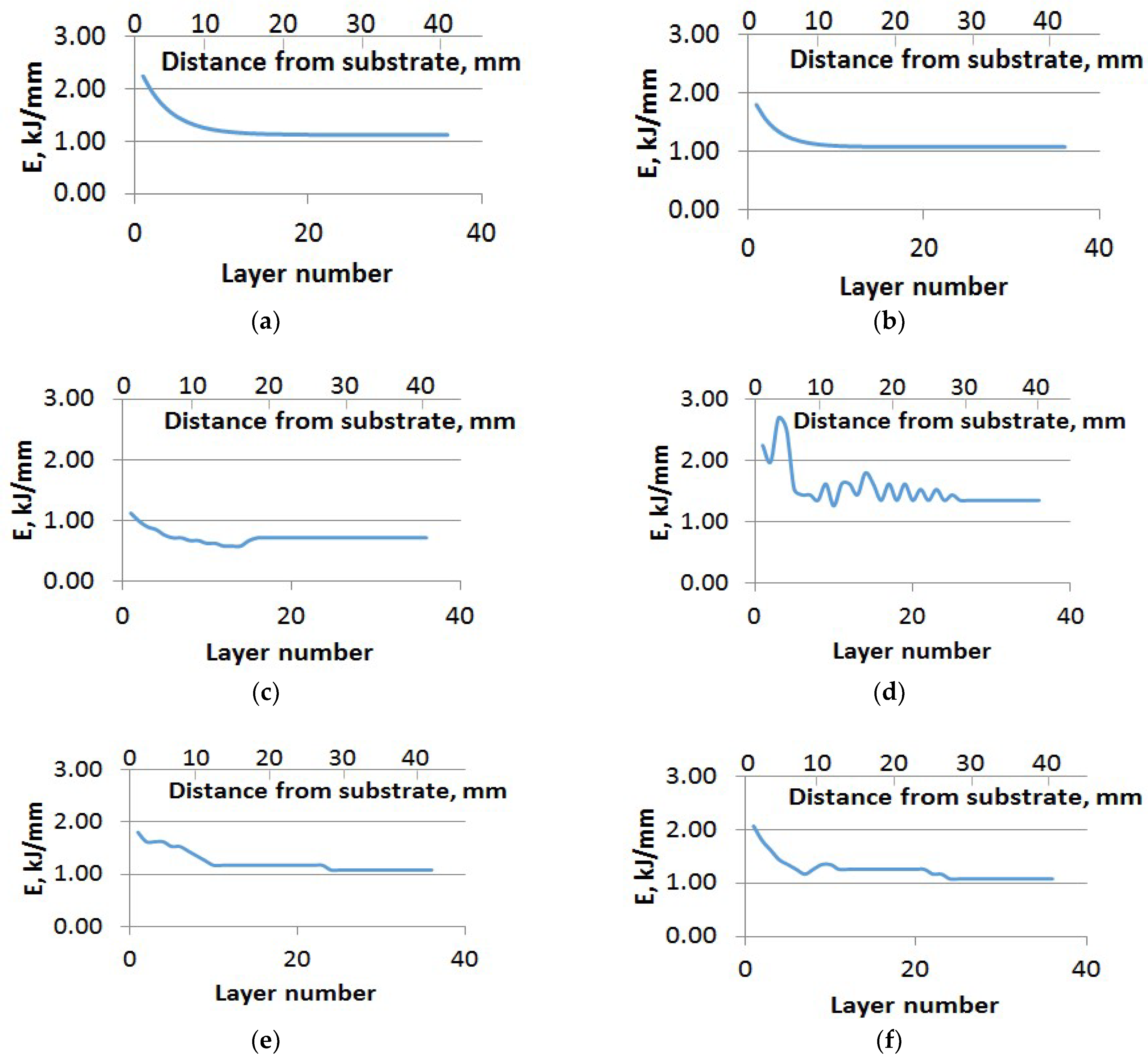
decreased heat dissipation by conduction into the substrate through the previously formed layers as the height of the product increased;
-
non-decreasing heat input at the level of 0.72 kJ/mm (see Figure 2c) during the formation of the final layers of the product, starting from the sixteenth.
Multidirectional 3D printing led to the excessive melting of the additive product due to the largest heat input realized in this study (product IV), with a final heat input of 1.35 kJ/mm (see Table 1 and Figure 2d).
By preheating the substrate to 400 °C and maintaining this temperature throughout the additive process, the heat input was reduced to 1.08 kJ/mm (see Table 1 and Figure 2e).
Partial suppression of the radiative component of heat dissipation (product VI) reduced the heat input to 1.08 kJ/mm (see Table 1 and Figure 2f).
The comparison of the shape of all six additive products to the required shape with overall dimensions of 56 × 41 × 11 mm3 (length × height × width), shown in Figure 3 by dashed lines, indicated that the dimensions of product I and product VI have the smallest deviations from that specified.

3.2. Macrostructure Features

Figure 4 shows images of the macrostructure in longitudinal sections of additive products labeled I–VI. A common feature of all additive products was the formation of directionally growing colonies of dendrites whose growth was epitaxial and uninterrupted by the deposition of additive layers. Within each colony, there was strictly parallel growth of first-order dendritic axes with weakly developed second-order axes (see Figure 5a).
In [20] it was shown that the primary dendritic arms were predominantly oriented along the {001} crystallographic direction. At the same time, in the product labeled “0”:
-
the mutual disorientation of the primary dendrite arms, and hence of the dendrite colonies, did not exceed 9 degrees;
-
the volume fraction of dendrite colonies without mutual disorientation equaled 0.54.
The material of the product with such parameters of macrostructure and microstructure fully meets the requirements for products with directed structure (mutual disorientations should not exceed 15 degrees [23,24]), and partially meets the requirements for materials with a single crystal structure [21].
Another common feature of each additive product was the presence of horizontally grown dendrites in the last layer (see Figure 5b and Figure 6a). It is worth noting that the crystallization of dendrites in the horizontal direction did not occur in the entire last layer, but only in its upper part. This is due to the insufficient heat transfer to the lower layers via thermal conductivity and the increasing contribution of the radiation component of the heat transfer. This process is described in more detail in [25].
The features of the material macrostructure of the additive products with marking I–VI, formed in the EBAM process, were established:
-
Absence of macro defects of a discontinuities type (cracks of all kinds, pores, non-melting).
-
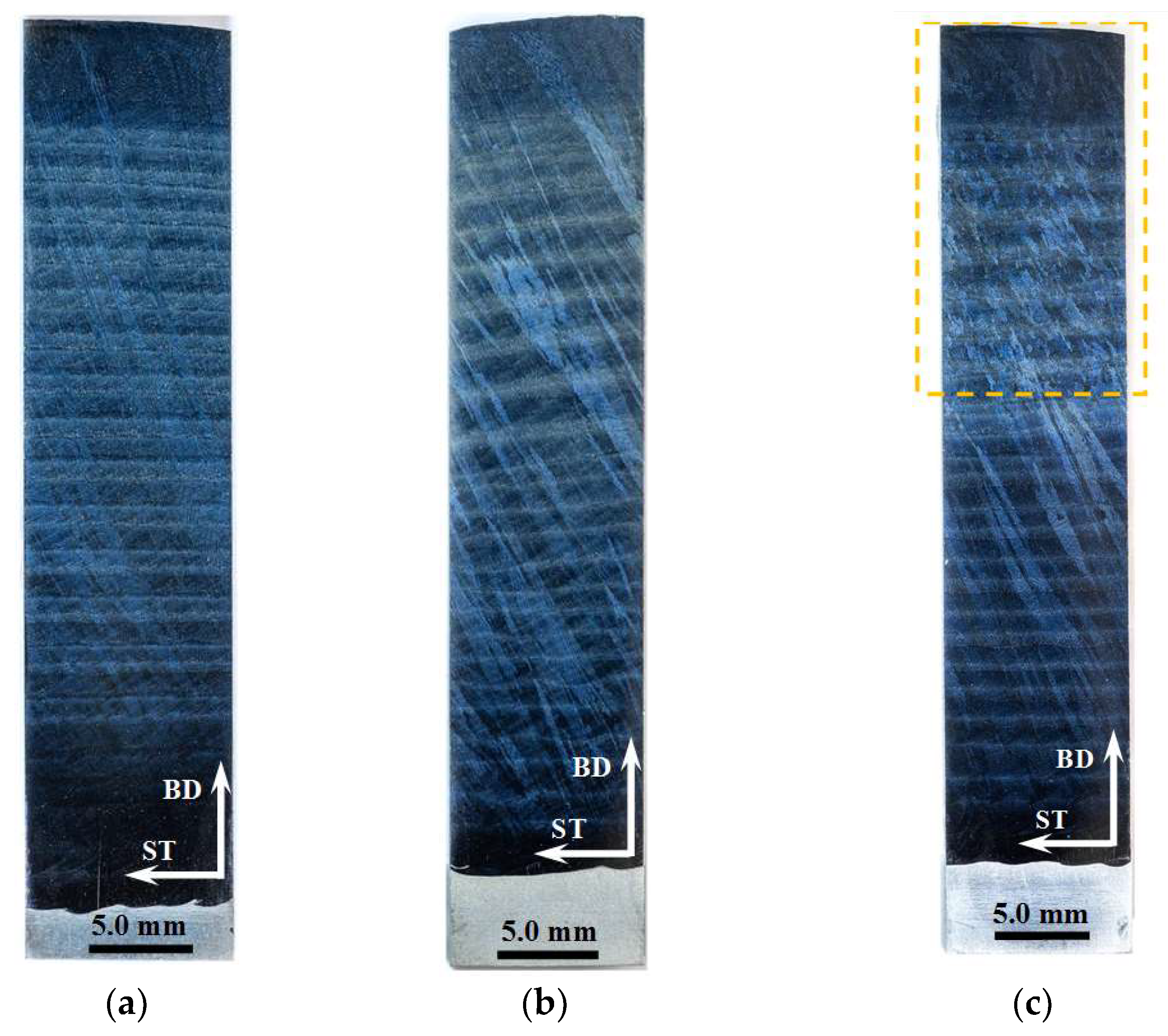
Homogeneous directional structure (except for the product with marking IV, formed by multidirectional 3D printing) from the transition layer on the substrate to the final additive layer.
-
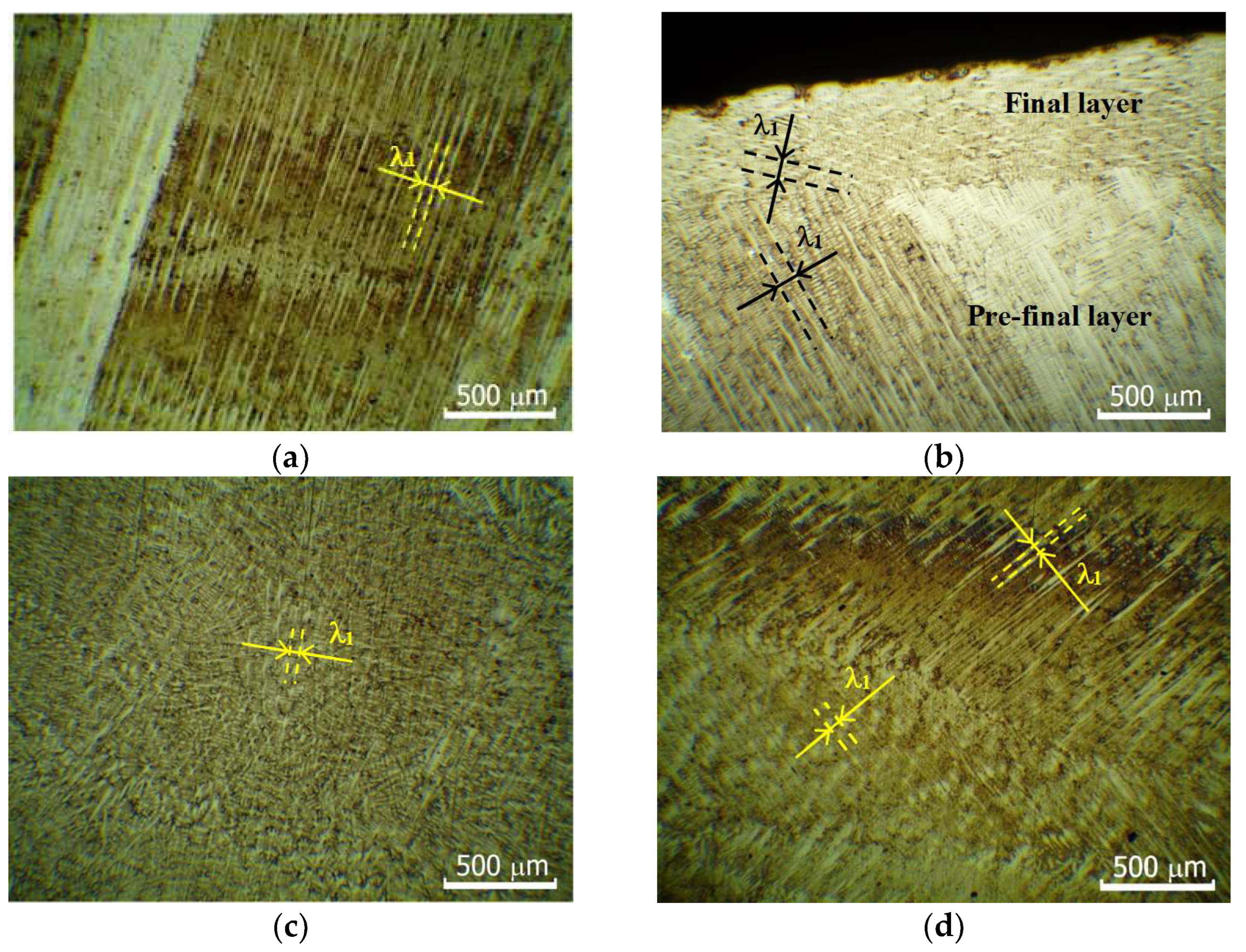
Colonies of dendrites forming the directional structure tilted from the vertical direction of growth of each product (BD) in the direction of unidirectional 3D printing (scanning trajectory, ST) by an angle Ψ from 16 to 38° (see Table 2). In the case of multidirectional 3D printing (product IV), the angle of inclination of the dendritic colonies Ψ increased significantly. The tilt ranged from 37.3 to 51.1° in the 3D printing (ST) direction and from 38.0 to 51.9° in the anti-parallel 3D printing (ST) direction, see Table 2 and Figure 4d.
Notably, in additive product III the directional dendrite growth was interrupted at 25 mm from the substrate. In Figure 4c the region with non-directional growth of dendrites is marked with a closed dashed line; Figure 5c shows the microstructure of this region. In this additive process, the rate of the worktable movement was doubled, resulting in an inversely proportional decrease in heat input. This, in turn, apparently led to a decrease in the temperature gradient value to one that did not meet the conditions for directional solidification. The structure of additive product IV also showed some differences. In this approach, a multidirectional 3D printing strategy was applied, which resulted in the formation of dendritic colonies of zigzag-directed morphology (see Figure 4d and Figure 5d). According to [26,27], zigzag morphology is not expected in the strategy of multidirectional 3D printing at higher values of heat input. However, in our case, increased values of heat input in the first layer up to 2.25 kJ/mm and 2.60 kJ/mm in the third layer (see Table 2 and Figure 2d) led to excessive melting in the layers. This ultimately led to unsatisfactory deviations from the specified dimensions and the shape of the product (Figure 3d).

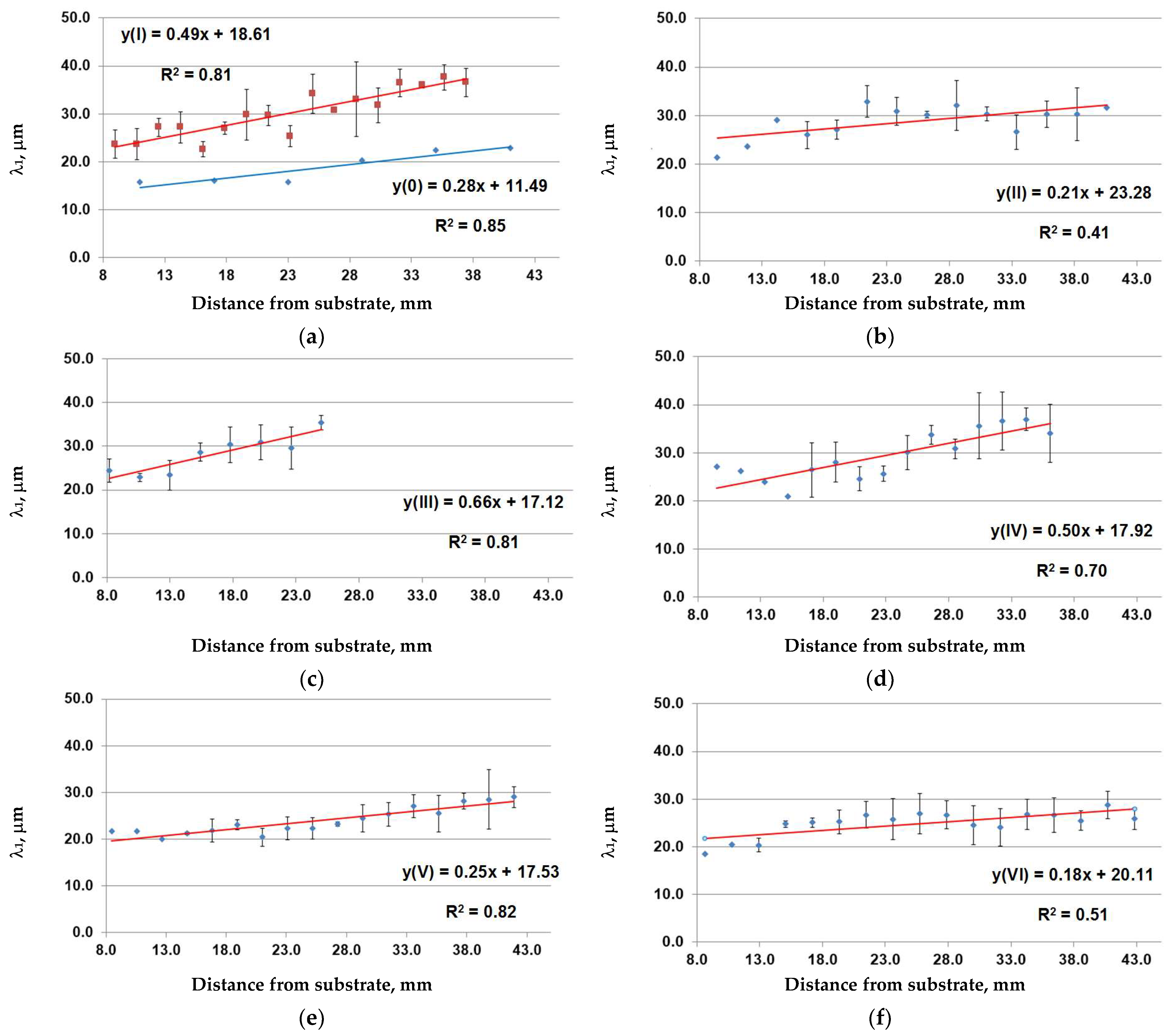
3.3. Microstructure State Features

Irrespective of the chosen technological mode, all the samples of ZhS32 alloy obtained by EBAM had the same structural-phase composition: dendritic axes and an interdendritic space. The description of the peculiarities of the phase composition of additive products is beyond the scope of the present study. These features are presented in [18]. Here we note that carbide phases (the light component in Figure 6) were localized in the interdendritic space, as well as eutectic γ/γ′ and, possibly, Laves phases.
The main parameter of the dendritic structure—the average primary dendrite arm spacing (PDAS) λ1 was determined by counting the intersections of the primary arms of the metallographic section surface. Figure 5a and Figure 6 show the characteristic primary dendrite arm spacing λ1.
Figure 7 shows the results of determining λ1 at different distances from the substrate in the material of all additive products formed and studied in this paper. To determine PDAS, three colonies of dendrites were considered at each height analyzed, and at least fifty measurements of the distances between parallel growing axes of first-order dendrites were carried out. The results of PDAS measurements presented in Figure 7 start from the distance of 8.0 mm from the substrate and end at the pre-final layer. Such limitations of the measurement area were caused by the following. Starting from the specified distance from the substrate, the influence of the substrate on the additive product material is completely compensated for, as shown in [25]. Meanwhile, in the final layers of the additive products the material structure differs significantly from the previous layers, as mentioned above, and is represented by horizontally growing dendrites.
Mathematical processing of the experimental results of PDAS measurements using the method of least squares was performed. For each product it was revealed that there was a gradual increase in PDAS as the distance from the substrate increased. In the case of product III, there was no formation of directionally growing dendrites at a height of 25 mm from the substrate and above. This was probably due to the fact that the crystallization rate was so high (due to the increase in the rate of the worktable movement) that the formed structure tended to be more equiaxed.
When manufacturing products from the ZhS32 alloy using the EBAM method, it is necessary to take into account the following peculiarities:
-
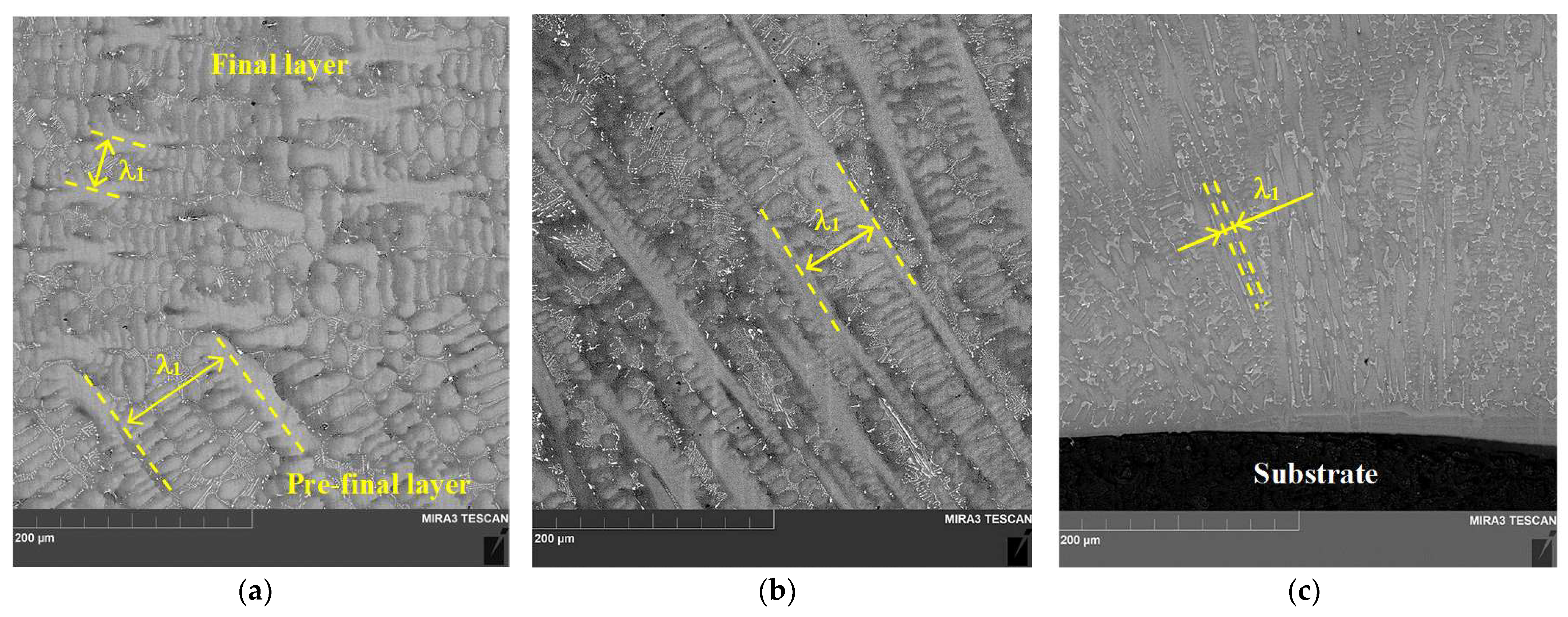
The last layer is not re-melted, which leads to changes in the size and morphology of the formed structure.
-
There is a need to increase the value of heat input to the first layers, which also leads to changes in the size and morphology of the formed structure.
Considering the above, we can conclude that the material structure of the products obtained by EBAM is most homogeneous, starting from the height of 15 mm from the substrate and is maintained until the penultimate layer. Table 3 shows data on the distribution of PDAS in the homogeneous region for the products obtained by different modes. Data for mode III are not shown in Table 3 because no columnar, directionally growing dendrites are formed in its homogeneous region.
According to the data in Table 3, the smallest interval of PDAS values corresponds to mode VI, which indicates the most homogeneous structure of the formed material. The largest interval of PDAS values corresponds to modes I and IV, so the structure is the least homogeneous when using these modes. Considering the data in Table 1 and Table 3, we can conclude the following. The application of substrate heating or the suppression of the radiation component of heat dissipation allow to obtain a thinner dendritic structure and to reduce the resulting heat input, which increases the performance and energy efficiency of EBAM. It also allows for an increase the aluminum content in the additive material, as shown below.

3.4. Chemical Composition Features

Table 4 shows the results of the X-ray fluorescence analysis of the additive material at a distance of 28 mm from the substrate. The elemental composition result was taken as the arithmetic mean of three measurements. Arithmetic means and standard deviations were calculated using Niton XL3t GOLDD++ X-ray fluorescence spectrometer software (version HH-XRF_8.4H.4).
The elemental content values below the grade ones are highlighted in red, and the values above are highlighted in blue. In the first column of Table 4, in addition to the marking of additive products, the calculated values of heat input at a distance of 28 mm from the substrate are shown. This means that during each process of EBAM formation of additive products at a distance of 28 mm from the substrate, the specified heat input was supplied to the melt bath.
In order to evaluate the effect of heat input on the elemental composition of additive products, the localization was chosen at such a distance from the substrate, where there is absolutely no influence of the substrate, which has been shown in a number of previous works, for example [23]. In addition, at this stage of additive product formation, the main technological parameters change insignificantly and monotonically, and the heat input values decrease slowly and monotonically, approaching the minimum.
The following conclusions can be drawn from an evaluation of the above results.
For all EBAM processes, a reduced aluminum content (by 0.80–1.89 wt.% with respect to the minimum allowable grade composition) was revealed due to the selective evaporation of this fusible element during the processing in vacuum. In this case, aluminum is replaced by the most refractory alloying elements such as cobalt and tungsten.
It is possible that the reduced content of aluminum as a base γ′-phase will have a negative impact on the heat resistance properties of the additive product. However, it is beyond the scope of this study to determine the mechanical properties at elevated temperatures of the additive product material of the alloy used.
The most approximate value of aluminum content in the material of additive product III is provided at the lowest applied value of heat input—0.72 kJ/mm. However, further reduction in heat input is unreasonable as it will lead to the formation of macro defects such as cracks [29,30].
Obviously, in order to obtain additive products with an aluminum content corresponding to that of the grade, the raw material with higher aluminum content is required.
The reduced content of tantalum (by 0.61–0.81 wt.% less than the minimum allowable grade composition), in our opinion, is associated with the selective dropping of carbide phases (which presumably contain the majority of tantalum) during the preparation of metallographic sections. The sections were subjected to X-ray fluorescence analysis in order to determine the elemental composition. Note that the content of tantalum in the samples prepared by the ion milling method corresponds to the grade values, see, for example, Table 3 in [20].

4. Conclusions

In the present study, several schemes of heat input and heat removal from the melt bath in the EBAM process under the conditions of unidirectional and multidirectional 3D printing strategy were applied. The following characteristics of the elemental composition, macro-, and microstructure of the material of the additive products made of the superalloy ZhS32 were determined:
-
The material of products formed in the unidirectional 3D printing strategy has a directional macrostructure in the entire internal volume except for the final layer with a thickness from 0.5 to 3.5 mm.
-
In the case of the multidirectional 3D printing strategy, the product material is formed with a characteristic directional zigzag macrostructure.
-
In most cases, the dendritic colonies forming the directional structure are tilted from the vertical growth direction of each product toward the unidirectional 3D printing direction by an angle in a narrow range of (21–24) degrees. Reduced heat dissipation achieved by suppression of the heat conduction mechanism through the substrate into the cooled table or substrate heating accounts for the wide range of tilt angles (16–38) degrees.
-
With increasing distance from the substrate, the average primary dendrite arm spacing increases monotonically by 1.3–3.0 times, depending on the heat input and the conditions of heat removal from the melt bath.
-
Partial suppression of the radiation component of heat removal allows to reduce the heat input to the one of the lowest values realized in this study, while the shape and dimensions of the additive product have the smallest deviations from the specified ones in comparison with all the other additive products.
-
The material of all the additive products has a lower aluminum content due to selective evaporation of this element with lowest melting point during the vacuum conversion process. In this case, aluminum is replaced by the most refractory alloying element in the form of tungsten. In order to obtain additive products with an aluminum content equal to the grade chemical composition, a raw material with higher aluminum content is required.

Author Contributions

Conceptualization, S.F.; methodology, S.F.; formal analysis, S.F., E.K. and D.G.; investigation, S.F., D.G. and K.O.; resources, E.K. and S.N.; data curation, S.F. and D.G.; writing—original draft preparation, S.F. and D.G.; writing—review and editing, S.F. and D.G.; visualization, D.G., K.O. and S.N.; supervision, S.F.; project administration, E.K.; funding acquisition, S.F. and D.G. All authors have read and agreed to the published version of the manuscript.

Funding

The investigation was supported by the Russian Science Foundation grant No. 22-22-00891, https://rscf.ru/en/project/22-22-00891/ (accessed on 12 August 2023).

Data Availability Statement

Data are contained within the article.

Acknowledgments

The SEM research was carried out using equipment of Tomsk Regional Core Shared Research Facilities Center of National Research Tomsk State University.

Conflicts of Interest

The authors declare no conflict of interest.

References

  1. Körner, C.; Ramsperger, M.; Meid, C.; Bürger, D.; Wollgramm, P.; Bartsch, M.; Eggeler, G. Microstructure and Mechanical Properties of CMSX-4 Single Crystals Prepared by Additive Manufacturing. Metall. Mater. Trans. A 2018, 49, 3781–3792. [Google Scholar] [CrossRef] [Green Version]
  2. Basak, A.; Raghu, S.H.; Das, S. Microstructures and Microhardness Properties of CMSX-4® Additively Fabricated Through Scanning Laser Epitaxy (SLE). J. Mater. Eng. Perform. 2017, 26, 5877–5884. [Google Scholar] [CrossRef]
  3. Dereje, T.; Palani, S.; Desta, M.; Čep, R. Experimental Investigation into the Influence of the Process Parameters of Wire Electric Discharge Machining Using Nimonic-263 Superalloy. Materials 2023, 16, 5440. [Google Scholar] [CrossRef] [PubMed]
  4. Liu, Y.; Wang, Y.; Wei, D.; Jiang, X.; Tao, Q. Modeling of Creep Deformation Behavior of DZ411 and Finite Element Simulation of Turbine Blade. Metals 2023, 13, 1389. [Google Scholar] [CrossRef]
  5. He, R.; Li, M.; Han, X.; Feng, W.; Zhang, H.; Xie, H.; Liu, Z. Experimental Study of As-Cast and Heat-Treated Single-Crystal Ni-Based Superalloy Interface Using TEM. Nanomaterials 2023, 13, 608. [Google Scholar] [CrossRef]
  6. Krawczyk, J.; Bogdanowicz, W. The Influence of the Cooling Bores on the Dendritic Structure and Crystal Orientation in Sin-gle-Crystalline Cored CMSX-4 Turbine Blades. Materials 2021, 14, 3966. [Google Scholar] [CrossRef]
  7. Liu, Z.; Guo, S.; Liu, X.; Ye, J.; Yang, Y.; Wang, X.-L.; Yang, L.; An, K.; Liu, C. Micromechanical characterization of casting-induced inhomogeneity in an Al0.8CoCrCuFeNi high-entropy alloy. Scr. Mater. 2011, 64, 868–871. [Google Scholar] [CrossRef]
  8. Gong, X.; Anderson, T.; Chou, K. Review on powder-based electron beam additive manufacturing technology. Manuf. Rev. 2014, 1, 2. [Google Scholar] [CrossRef]
  9. Bento, J.B.; Wang, C.; Ding, J.; Williams, S. Process Control Methods in Cold Wire Gas Metal Arc Additive Manufacturing. Metals 2023, 13, 1334. [Google Scholar] [CrossRef]
  10. Yang, T.; Mazumder, S.; Jin, Y.; Squires, B.; Sofield, M.; Pantawane, M.V.; Dahotre, N.B.; Neogi, A. A Review of Diagnostics Methodologies for Metal Additive Manufacturing Processes and Products. Materials 2021, 14, 4929. [Google Scholar] [CrossRef]
  11. Wilms, M.B.; Rittinghaus, S.-K. Laser Additive Manufacturing of Oxide Dispersion-Strengthened Copper–Chromium–Niobium Alloys. J. Manuf. Mater. Process. 2022, 6, 102. [Google Scholar] [CrossRef]
  12. Li, B.; Wang, B.; Zhu, G.; Zhang, L.; Lu, B. Low-Roughness-Surface Additive Manufacturing of Metal-Wire Feeding with Small Power. Materials 2021, 14, 4265. [Google Scholar] [CrossRef] [PubMed]
  13. Kolubaev, E.A.; Rubtsov, V.E.; Chumaevsky, A.V.; Astafurova, E.G. Micro-, Meso- and Macrostructural Design of Bulk Metallic and Polymetallic Materials by Wire-Feed Electron-Beam Additive Manufacturing. Phys. Mesomech. 2022, 25, 479–491. [Google Scholar] [CrossRef]
  14. Zykova, A.; Nikolaeva, A.; Panfilov, A.; Vorontsov, A.; Nikonenko, A.; Dobrovolsky, A.; Chumaevskii, A.; Gurianov, D.; Filippov, A.; Semenchuk, N.; et al. Microstructures and Phases in Electron Beam Additively Manufactured Ti-Al-Mo-Zr-V/CuAl9Mn2 Al-loy. Materials 2023, 16, 4279. [Google Scholar] [CrossRef]
  15. Astafurova, E.; Maier, G.; Melnikov, E.; Astafurov, S.; Panchenko, M.; Reunova, K.; Luchin, A.; Kolubaev, E. Tempera-ture-Dependent Deformation Behavior of “γ-austenite/δ-ferrite” Composite Obtained through Electron Beam Additive Manufacturing with Austenitic Stainless-Steel Wire. J. Compos. Sci. 2023, 7, 45. [Google Scholar] [CrossRef]
  16. ISO/TR 25901-1; Welding and Allied Processes. Vocabulary. Part 1. General Terms. ISO: Geneva, Switzerland, 2016.
  17. Hales, S.; Domack, C. Electron Beam Freeform Fabrication of Dissimilar Materials: Cracking in Inconel® 625 Deposited on GRCop-84//Technical report.-NASA/TP–2020-5005040.-2020.-84P. Available online: https://www.researchgate.net/publication/345688570_Electron_Beam_Freeform_Fabrication_of_Dissimilar_Materials_Cracking_in_Inconel_R_625_Deposited_on_GRCop-84 (accessed on 12 August 2023).
  18. Tarasov, S.Y.; Filippov, A.V.; Savchenko, N.L.; Fortuna, S.V.; Rubtsov, V.E.; Kolubaev, E.A.; Psakhie, S.G. Effect of heat input on phase content, crystalline lattice parameter, and residual strain in wire-feed electron beam additive manufactured 304 stainless steel. Int. J. Adv. Manuf. Technol. 2018, 99, 2353–2363. [Google Scholar] [CrossRef]
  19. Utyaganova, V.R.; Filippov, A.V.; Shamarin, N.N.; Vorontsov, A.V.; Savchenko, N.L.; Fortuna, S.V.; Gurianov, D.A.; Chumaevskii, A.V.; Rubtsov, V.E.; Tarasov, S.Y. Controlling the porosity using exponential decay heat input regimes during electron beam wire-feed additive manufacturing of Al-Mg alloy. Int. J. Adv. Manuf. Technol. 2020, 108, 2823. [Google Scholar] [CrossRef]
  20. Fortuna, S.; Gurianov, D.; Nikonov, S.; Ivanov, K.; Mironov, Y.; Vorontsov, A. Features of the Macro-, Micro-, and Fine Structure of the Nickel Superalloy Product Material Formed by the Method of Electron Beam Additive Manufacturing. Materials 2022, 15, 8882. [Google Scholar] [CrossRef]
  21. Pistor, J.; Breuning, C.; Körner, C. A Single Crystal Process Window for Electron Beam Powder Bed Fusion Additive Manufacturing of a CMSX-4 Type Ni-Based Superalloy. Materials 2021, 14, 3785. [Google Scholar] [CrossRef]
  22. Parsa, A.B.; Ramsperger, M.; Kostka, A.; Somsen, C.; Körner, C.; Eggeler, G. Transmission Electron Microscopy of a CMSX-4 Ni-Base Superalloy Produced by Selective Electron Beam Melting. Metals 2016, 6, 258. [Google Scholar] [CrossRef] [Green Version]
  23. Yu, J.; Li, J.R.; Liu, S.Z.; Han, M. Creep Anisotropy in Single-Crystal Superalloy DD6 near the [001] Orientation. In Superalloys 2020; The Minerals, Metals & Materials Series; Springer: Cham, Germany, 2020. [Google Scholar]
  24. Albrecht, R.; Zubko, M.; Gancarczyk, K.; Szeliga, D. High-Resolution Diffraction Imaging of Misorientation in Ni-Based Single Crystal Superalloys. In Superalloys 2020; The Minerals, Metals & Materials Series; Springer: Cham, Germany, 2020. [Google Scholar]
  25. Fortuna, S.V.; Gurianov, D.A.; Kalashnikov, K.N.; Chumaevskii, A.V.; Mironov Yu, P.; Kolubaev, E.A. Directional Solidification of a Nickel-Based Superalloy Product Structure Fabricated on Stainless Steel Substrate by Electron Beam Additive Manufacturing. Metall. Mater. Trans. A 2021, 52, 857–870. [Google Scholar] [CrossRef]
  26. Filippov, A.; Shamarin, N.; Moskvichev, E.; Savchenko, N.; Kolubaev, E.; Khoroshko, E.; Tarasov, S. Heat Input Effect on Microstructure and Mechanical Properties of Electron Beam Additive Manufactured (EBAM) Cu-7.5wt.%Al Bronze. Materials 2021, 14, 6948. [Google Scholar] [CrossRef]
  27. Filippov, A.; Shamarin, N.; Moskvichev, E.; Savchenko, N.; Kolubaev, E.; Khoroshko, E.; Tarasov, S. The Effect of Heat Input, Annealing, and Deformation Treatment on Structure and Mechanical Properties of Electron Beam Additive Manufactured (EBAM) Silicon Bronze. Materials 2022, 15, 3209. [Google Scholar] [CrossRef] [PubMed]
  28. Bykov, Y.G.; Zakharova, T.P.; Monastyrskaya, E.V.; Fishgoit, A.V.; Dushkin, A.M.; Demidov, A.G. Mechanical properties of high-temperature alloy ZhS32 at 1150–1250 °C. Met. Sci. Heat Treat. 2006, 48, 41–43. [Google Scholar] [CrossRef]
  29. Fortuna, S.V.; Gurianov, D.A.; Nikonov, S.Y.; Ivanov, K.V. About the features of the chemical composition of additive products from nickel-based superalloy. AIP Conf. Proc. 2020, 2310, 020101. [Google Scholar] [CrossRef]
  30. Gurianov, D.A.; Fortuna, S.V.; Osipovich, K.S. Defects formation features of nickel-based superalloy product obtained by wire-feed electron beam additive manufacturing. AIP Conf. Proc. 2019, 2167, 020125; [Google Scholar] [CrossRef]
Figure 1. Schemes of EBAM processes for the formation of additive products: 0—at the initial beam current Ii(0) = 25 mA, I—a similar EBAM process (at the initial beam current Ii(I) = Ii(0) = 25 mA) under conditions of a decrease in the heat-conducting component of heat removal (a); II—reduction in heat input by reducing the initial beam current Ii(II) = 20 mA (b); III—reduction in heat input due to the doubled worktable movement rate v = 40 mm/min (c); IV—multidirectional 3D printing with perpendicular bar feed relative to the scanning trajectory ST (d); V—reduction in heat input due to a decrease in the initial beam current Ii(V) = 20 mA under conditions of preliminary heating of the substrate to 400 °C (e); VI—reduction in heat input by reducing the initial beam current Ii(VI) = 23 mA under conditions of partial suppression of the radiative component of heat removal (f). BD—building direction, ST—scanning trajectory.
Metals 13 01457 g001
Figure 2. The dependence of the heat input value calculated by Equation (1) on the number of layers deposited and the distance from the substrate for products: 0 and I—(a); II—(b); III—(c); IV—(d); V—(e); and VI—(f).
Metals 13 01457 g002
Figure 3. General view of additive products I, II, III, IV, V, VI—(a), (b), (c), (d), (e), (f), respectively. The dashed lines show the overall dimensions of 56 × 41 × 11 mm3 (length × height × width) specified during 3D printing of additive products.
Metals 13 01457 g003
Figure 4. Characteristic images of the macrostructure of the material of additive products in a longitudinal section (parallel to the 3D printing trajectory ST). Macrostructure of products I, II, III, IV, VI—(a), (b), (c), (d), (e), and (f), respectively. As examples, the angles of inclination of dendritic colonies relative to the direction of additive growth BD Ψ—(d,f) are shown.
Metals 13 01457 g004aMetals 13 01457 g004b
Figure 5. Characteristic microstructure images of the products: I—at a distance of 20.0 mm from the substrate (a); II—final and pre-final layers (b); III—at a distance of 30.0 mm from the substrate (c); IV—at a distance of 20.0 mm from the substrate (d). The characteristic primary dendrite arm spacing λ1 is shown.
Metals 13 01457 g005
Figure 6. Characteristic SEM image of the dendritic structure of the product 0: final and pre-final layers (a), half height (b), and the substrate (c). The characteristic primary dendrite arm spacing λ1 is shown.
Metals 13 01457 g006
Figure 7. The dependence of PDAS on the distance from the substrate for products: 0 and I—(a); II—(b); III—(c); IV—(d); V—(e); and VI—(f).
Metals 13 01457 g007
Table 1. Values of the main technological parameters of the EBAM process and heat input.
ProductU, kVI, mAv, mm/minE, kJ/mm
0, I3025.0–12.5202.25–1.13
II20.0–12.0201.80–1.08
III25.0–16.0401.13–0.72
IV25.0–30.0–13.0202.25–2.60–1.35
V20.0–11.5201.80–1.08
VI23.0–12.0202.07–1.08
Table 2. Values of average angles of inclination of dendrite colonies relative to the direction of building direction (BD).
ProductAverage Tilt Angle Ψ in the Direction of Unidirectional Scanning Trajectory (ST), deg. *
0T: 24.2; M: 24.2; B: 23.2
IT: 15.8; M: 26.1; B: 30.1
IIT: 21.0; M: 31.9; B: 24.5
IIIT: 21.4; M: 21.4; B: 21.4
IVT: +51.1/−38.0; M: +37.3/−49.5; B: +46.7/−51.9
VT: 16.0–26.0; M: 21.0; B: 26.4
VIT: 23.7; M: 31.2; B: 24.3
*—Angles of inclination Ψ of the primary dendritic axes (and consequently of the dendritic colonies) at three levels: at the substrate (B), at half height of the product (M), and in the penultimate layer (T).
Table 3. Ranges of PDAS values in the homogeneous region of difference products.
ProductPDAS, μmStd. Dev., μm
I22.6–37.60.4–7.8
II25.9–32.90.7–8.1
IV24.5–37.01.6–6.8
V20.4–29.00.3–6.4
VI24.0–28.80.7–4.3
Table 4. Chemical composition (wt.%) of additive products and the initial filament from superalloy ZhS32. The color shows the non-conformity of the brand composition—red below and blue in excess of the regulated values.
Product/E, kJ/mmAlCrFeCoNbMoTaWReC
Elements Content (wt.%)
0/1.133.81 ± 0.434.97 ± 0.060.042 ± 0.0129.76 ± 0.081.70 ± 0.021.23 ± 0.013.06 ± 0.089.49 ± 0.133.98 ± 0.11not * defined
I/1.134.70 ± 0.234.96 ± 0.060.029 ± 0.0129.62 ± 0.071.63 ± 0.021.20 ± 0.012.89 ± 0.079.24 ± 0.113.96 ± 0.11
II/1.084.69 ± 0.244.91 ± 0.060.047 ± 0.0129.59 ± 0.081.62 ± 0.021.19 ± 0.012.95 ± 0.079.23 ± 0.133.90 ± 0.11
III/0.724.90 ± 0.295.09 ± 0.080.049 ± 0.0129.73 ± 0.231.71 ± 0.061.25 ± 0.053.05 ± 0.139.53 ± 0.353.95 ± 0.18
IV/1.354.44 ± 0.244.96 ± 0.060.044 ± 0.0129.69 ± 0.081.72 ± 0.021.23 ± 0.013.06 ± 0.079.43 ± 0.123.96 ± 0.11
V/1.084.66 ± 0.235.01 ± 0.060.038 ± 0.0129.56 ± 0.071.63 ± 0.021.21 ± 0.012.89 ± 0.079.35 ± 0.123.95 ± 0.11
VI/1.084.65 ± 0.254.95 ± 0.060.046 ± 0.0139.57 ± 0.081.65 ± 0.021.21 ± 0.012.95 ± 0.079.33 ± 0.124.00 ± 0.11
Initial filament5.73 ± 0.184.99 ± 0.130.11 ± 0.109.27 ± 0.111.57 ± 0.131.16 ± 0.124.03 ± 0.328.48 ± 0.443.88 ± 0.31
Superalloy ZhS32 [28]5.7–6.24.5–5.3≤0.59.0–9.51.4–1.80.9–1.33.7–4.48.1–8.93.6–4.30.13–0.20
* The carbon content is not determined by X-ray fluorescence analysis.
Disclaimer/Publisher’s Note: The statements, opinions and data contained in all publications are solely those of the individual author(s) and contributor(s) and not of MDPI and/or the editor(s). MDPI and/or the editor(s) disclaim responsibility for any injury to people or property resulting from any ideas, methods, instructions or products referred to in the content.

