Article

Effect of Thermo-Mechanical Processing on Initiation and Propagation of Stress Corrosion Cracking in 304L Austenitic Stainless Steel

Central Research Institute, Korea Hydro and Nuclear Power Co., Ltd., Daejeon 34101, Republic of Korea
Metals 2023, 13(8), 1458; https://doi.org/10.3390/met13081458
Submission received: 11 June 2023 / Revised: 5 August 2023 / Accepted: 7 August 2023 / Published: 13 August 2023

Abstract

:
Despite the high corrosion resistance of austenitic stainless steels (SSs), a significant reduction of stress corrosion cracking (SCC) resistance has been reported in cases of high residual stress and metastable microstructural features. In this study, the effect of thermo-mechanical processing (TMP) on the initiation and propagation of SCC in 304L SS was studied. To better understand the SCC mechanisms, three TMPs conditions—welded, solution annealed at 1050 °C for tens of seconds, and straightened—were used. The research focused on analyzing the initial microstructure, residual stress, and hardness along the depth direction to assess SCC resistance and establish correlations with the observed SCC modes. Experimental results demonstrated that transgranular SCC was observed in regions exhibiting elevated residual stress induced by welding and straightening processes. Furthermore, the presence of strain-induced martensite transformation and slip bands formed during plastic deformation were identified as additional factors contributing to the susceptibility of SCC. The study findings highlighted that the magnitude and distribution of residual stresses, in conjunction with microstructural evolution, could be varied depending on the specific TMP condition, leading to different SCC susceptibilities, cracking modes, and directions.

1. Introduction

Austenitic stainless steels (SSs) are used extensively as major metallic materials because of their favorable corrosion resistance and mechanical properties [1,2]. However, when exposed to high temperatures and high-pressure water environments, austenitic SSs are highly susceptible to stress corrosion cracking (SCC) [3]. Typically, SCC incidents occur in austenitic SSs as a result of the combined effects of tensile stresses and corrosive environments [4]. Surprisingly, in recent years, several cases of SCC have been reported in non-sensitized austenitic SSs under pressurized water reactor conditions [5,6,7]. Extensive research has focused on understanding the phenomenology of SCC in SSs, leading to the identification of significant variables, including water chemistry [8,9], testing temperature [10], degree and paths of the pre-strain [11], and surface electrochemical characteristics [12]. Of these factors, residual stresses and microstructural changes, which can be introduced during manufacturing and welding processes, play a crucial role in the occurrence of SCC in SSs [13,14]. S. Ghosh et al. [15] and A. Turnbull et al. [14] reported the susceptibility of machined 304 L and 304 SS to SCC in chloride-containing environments, respectively. They observed significant initiation of SCC micro-cracks on the machined surface and attributed the high SCC sensitivity to tensile residual stress. Furthermore, A. Rhouma et al. [16] reported that a blasted surface with compressive residual stress did not develop cracks when immersed in a MgCl2 solution, indicating that compressive residual stress had a beneficial effect on SCC resistance; therefore, tensile residual stress generally has a negative influence on SCC resistance. However, other studies [2,7] reached the opposite conclusion. L. Chang et al. [2] reported that machined surfaces of 304 SS with high tensile residual stresses did not exhibit SCC initiation. Moreover, a 1–2 µm thick ultrafine-grained layer resulting from machining improved SCC resistance and promoted more uniform oxidation of the material [7]. In summary, based on extensive literature, the residual stress and microstructure changes induced by thermo-mechanical processing (TMP) are closely associated with SCC initiation and early propagation. However, the exact mechanism behind this relationship remains complex and unresolved due to the challenges of clarifying the influence of machining on SCC initiation and early propagation, given the complexity of plastic deformation and the coupling of residual stress and microstructural changes. Simultaneously, there has been increased interest in understanding the correlation between SCC crack development and material attributes such as stress state and microstructural evolution, as efforts are made to enhance SCC resistance in these materials [13]. Therefore, it is crucial to conduct detailed investigations into the roles of TMP-induced residual stress in SCC crack development in order to gain a better understanding of SCC mechanisms in austenitic SSs.
In this paper, the combined effects of residual stress and microstructural evolution on 304L SS were evaluated to understand the effects of SCC resistance under the different TMP conditions. To measure the precise residual stress caused by TMP, the split-ring test was conducted by measuring the splitting distances. In addition, changes in hardness values along the depth direction were evaluated. The relationship between the residual stresses caused by microstructural evolution depending on the TMP condition and SCC resistance was also evaluated. The influence of TMP on crack propagation was also analyzed, highlighting the distinct behaviors observed in relation to the magnitude and distribution of residual stresses coupled with strain-induced martensite transformation. These factors could play major roles in determining crack propagation characteristics.

2. Materials and Methods

The material used in this study was a 304L austenitic SS tube with a nominal chemical composition of Fe-18.2Cr-8.1Ni-1.2Mn-0.3Si-0.02C (wt.%). The chemical composition of the material was measured using the inductively coupled plasma (ICP) method implemented using a CS Determinator (ELTRA CS-2000, Eltra GmbH, Haan, Germany), and confirmed the technical specification (ASTM A688/A688M-18) of the 304L SS tube. Of the tubes subjected to different TMP conditions, AW (As-welded), HT (heat-treated), and SR (straightened) tubes were used to understand SCC resistance depending on the microstructure features caused by the TMP. The HT tubes were subjected to solution annealing at 1050 °C for some tens of seconds followed by water quenching. SR tubes were straightened using the tube-drawing process using cross-rolls.
Specimens were fabricated from tubes with different TMPs using electrical discharge machining (EDM) to observe a cross-section, then mechanically polished down to 0.05 μm colloidal silica. Then, the specimens were lightly etched in 10% perchloric acid + 90% acetic acid at 20 V at room temperature for about 15 s to remove any residual colloidal silica as well as residual stress from the surface. To reveal the grain boundaries, the specimens were further etched with 60% HNO3 + 40% H2O at 0.6 V at room temperature for 60 s (ASTM E407).
The split-ring method, which is usually applied to thin tubes with thicknesses less than one-tenth of the outer diameter, was used to measure the circumferential residual stress of the tubes [17]. The tubes were cut into 70-mm lengths using EDM. The sections opposite the weld regions were also cut using EDM with a wire approximately 0.3 mm in diameter at a speed of 0.1 mm/min. Finally, splitting distances in the samples were measured in at least 30 locations using an optical microscope (OM, Leica DMi8, Wetzlar, Germany). Residual stress ( σ θ , MPa) was then calculated using the following equations [17,18],
σ θ = 4 M r n a 2 b 2 r 2 log b a + b 2 log r b + a 2 log a r + b 2 a 2 ,
n = b 2 a 2 2 4 a 2 b 2 log b a 2 ,
M r = α E 8 π b 2 a 2 2 4 a 2 b 2 log b a 2 2 b 2 a 2 ,
α = δ / r
where M r is the residual stress, a is the inner radius of the tube, b is the outer radius of the tube, r is the radius of ring thickness, E is the modulus of elasticity, and δ is the displacement in width after splitting.
Hardness distribution along the depth direction was assessed using micro-hardness measurements. Testing was conducted in regions opposite the weld region based on careful microstructural observations. The indentation interval was divided into five equal sections, each spaced precisely 0.2 mm away from both the outer and inner surfaces. Vickers micro-hardness tests were conducted with a 0.3 kg load, and hardness values were derived by averaging three hardness values for each section.
SCC testing was carried out following the standardized ASTM G36 method. A saturated solution of magnesium chloride that boiled at 155.0 ± 1.0 °C was used. The magnesium chloride solution was prepared by weighing 1200 g of reagent grade MgCl2·6H2O and adding it to a 2000 mL Erlenmeyer flask containing 30 mL of ultrapure water. The flask, equipped with a thermometer and covered with glass beads at the bottom, was heated on a hotplate set at about 155 °C. To maintain a constant temperature and concentration of the boiling MgCl2, care was taken to prevent the loss of condensate and water vapor by using a condenser cooling system. Once the solution was boiling at a temperature of 155.0 ± 1.0 °C, preparation of the testing environment was completed with a 42 wt.% of MgCl2 solution. Subsequently, the specimens were immersed in the boiling MgCl2 solution without any external stresses being applied. To quantify crack initiation, detailed observation was carried out every 150 min under a digital microscope after cleaning and drying the specimens with ultrapure water and acetone, respectively. The procedure was terminated once the specimens had been immersed in the corrosive environment for 600 min.
After SCC testing, electron backscatter diffraction (EBSD, EDAX Inc., Mahwah, NJ, USA) analysis was performed to observe the crack propagation mode and the evolution of phase near the crack. A step size of 0.1 μm was used to generate the EBSD maps. Then, post-data processing was conducted using orientation imaging microscopy (OIM) software (EDAX, TSL analysis v8, Mahwah, NJ, USA), which is capable of identifying inverse pole figure (IPF) phases.

3. Results

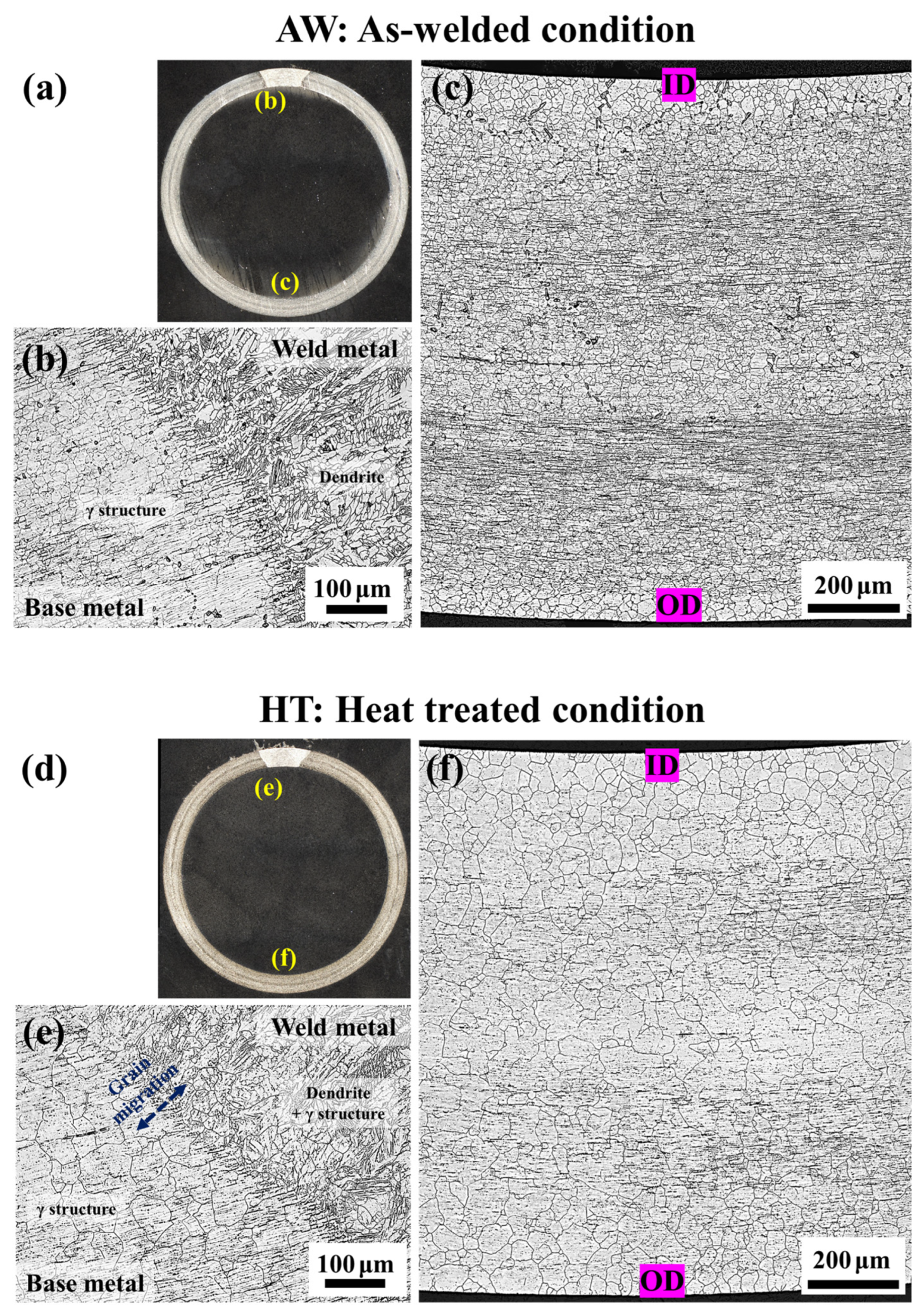
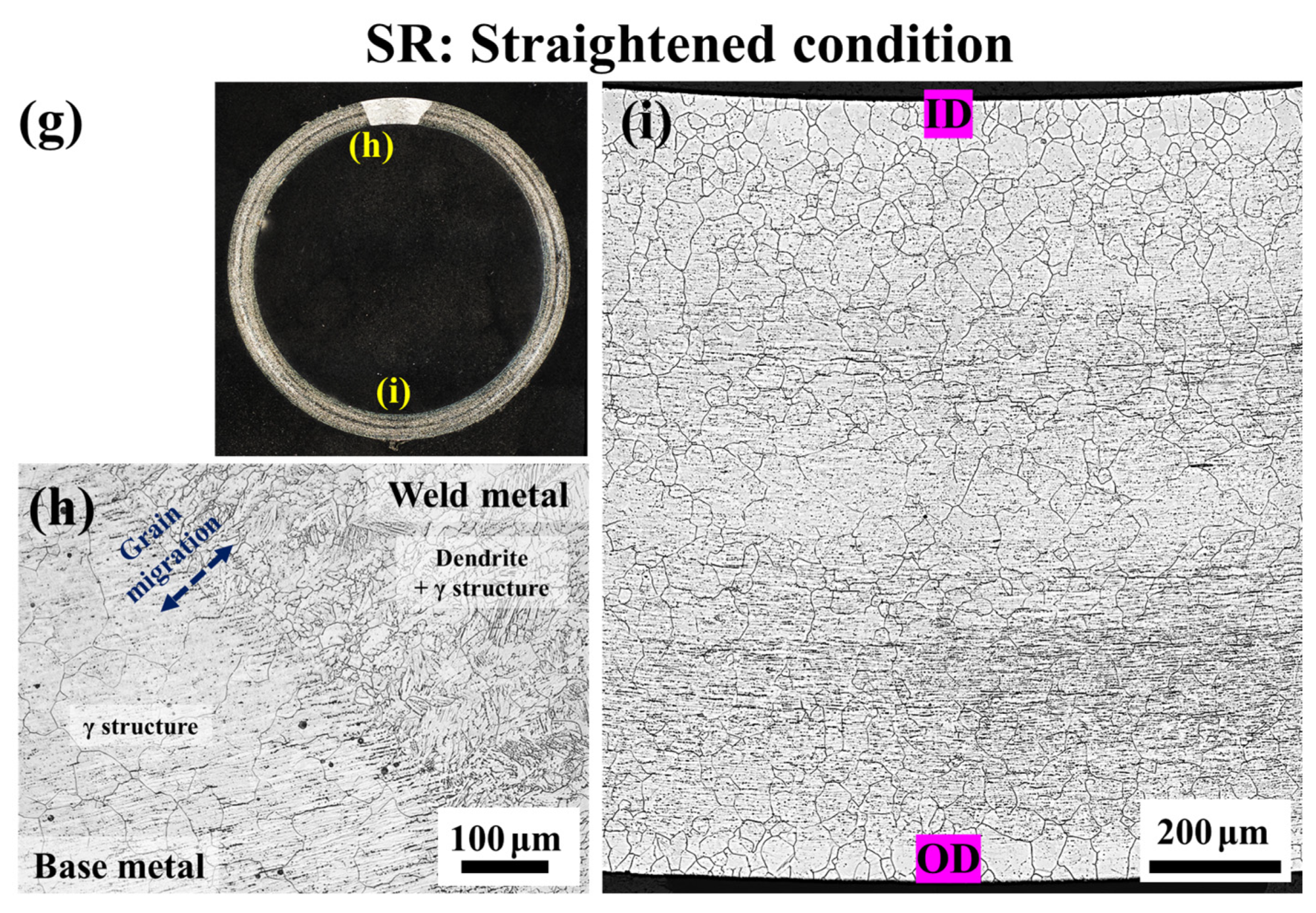
3.1. Initial Microstructure Depending on the TMP condition

Figure 1 presents OM micrographs of the evolution of microstructures under different TMP conditions: AW (Figure 1a–c), HT (Figure 1d–f), and SR (Figure 1g–i). The details of the TMP condition, measured grain size, and grain migration feature between the weld and base metals are summarized in Table 1. As shown in the figure, the average grain size increases from approximately 22 μm to 68 μm after heat treatment, resulting in a uniformly distributed grain structure (Figure 1f). Grain migration between the weld and base metal is observed in the HT condition but not the AW condition (Figure 1e). Furthermore, the weld metal exhibits an austenite structure with dendritic morphology, while only dendritic morphology is observed in the AW condition. The microstructure of the SR condition (Figure 1g–i) exhibits similarities with the HT condition in terms of grain size, austenite structure in the weld metal, and grain migration.

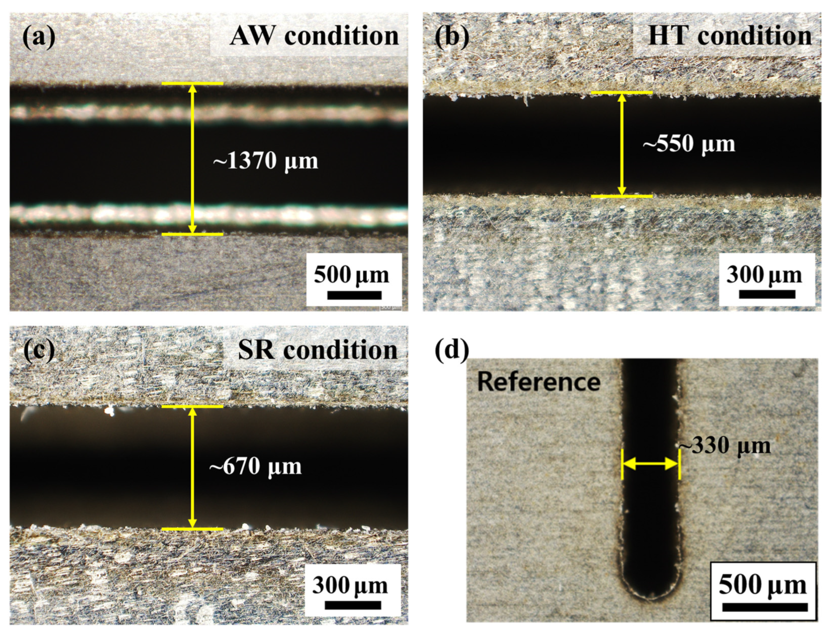
3.2. Residual Stress Measurement Using Split-Ring Test

After fabricating the split rings, splitting distances from the outer surfaces of the AW, HT, and SR tubes were compared, as shown in Figure 2; the results are summarized in Table 2. Significant differences in splitting distances were observed under the different TMP conditions. The AW sample, representing the initial TMP condition, exhibited a splitting distance of approximately 1373 μm (Figure 2a). In contrast, the HT sample showed a dramatic decrease in the splitting distance—around 550 μm (Figure 2b). After the straightening process, a slight increase in splitting distance—to approximately 670 μm—was observed (Figure 2c). Excluding the width of the cutting wire (~330 μm), splitting distances caused by residual stress under the AW, HT, and SR conditions were approximately 1043 μm, 219 μm, and 335 μm, respectively. Using the quantitative method described in Section 2, the residual stresses were calculated from the splitting distances of the tubes; these are summarized in Table 2. The AW sample exhibited a circumferential residual stress of approximately 1219 MPa, which was the highest among the three conditions. In contrast, the HT and SR samples showed relatively smaller residual stresses of approximately 256 MPa and 391 MPa, respectively, which were at least three times less than that of the AW sample. The slight increase in residual stress under the SR condition may be attributed to mechanical machining, which will be explained in a subsequent section.

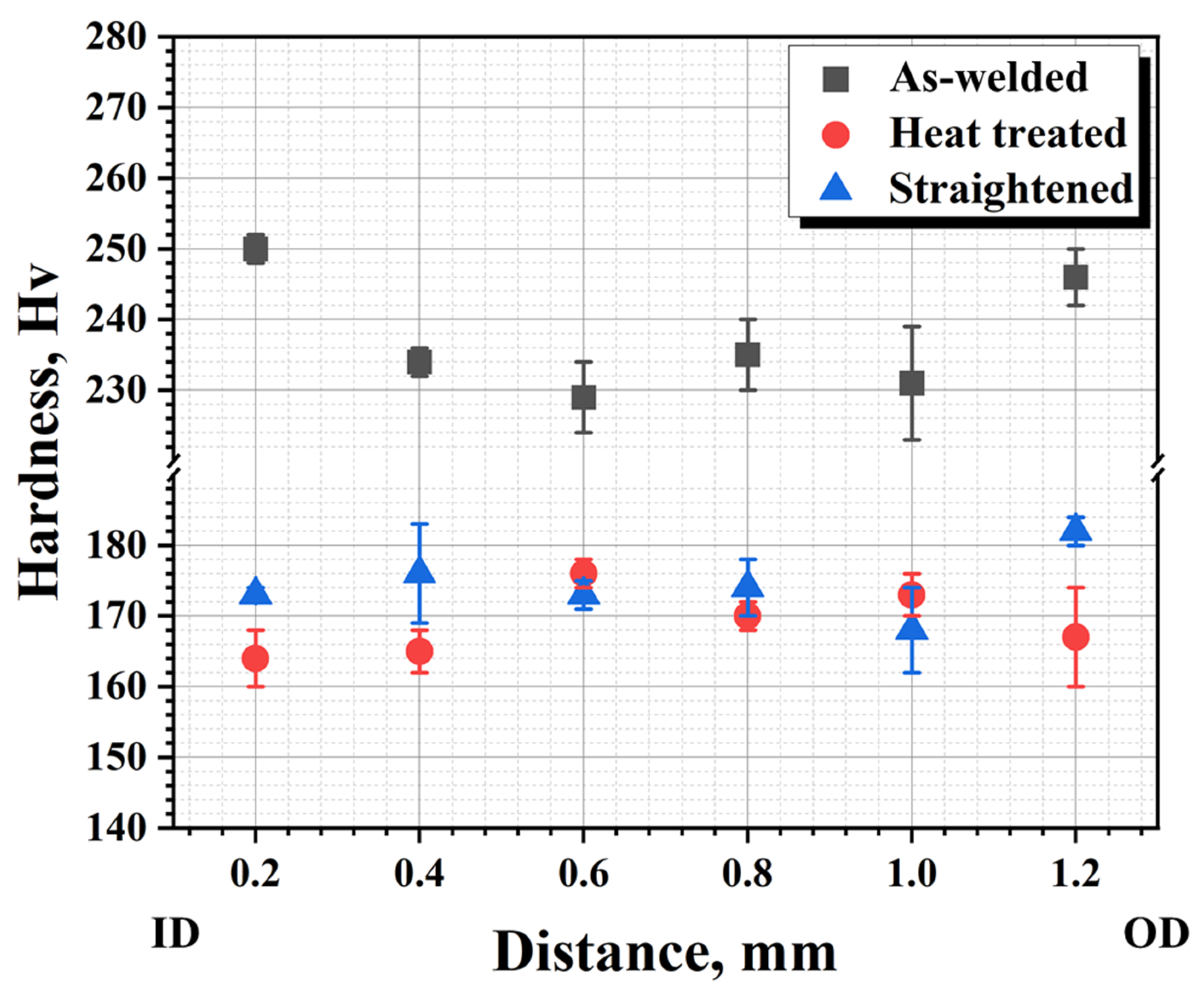
3.3. Micro-Hardness Measurements

The results of Vickers micro-hardness measurements for the AW, HT, and SR conditions are presented in Figure 3. In the case of the AW tubes, the hardness values in the inner and outer regions were similar, around 250 Hv, while slightly lower hardness values of approximately 230 Hv were observed in the middle region. As shown in Figure 1c, nonhomogeneous grain distribution was observed along the radial direction, with smaller grain structures present in the inner and outer regions and relatively larger grain sizes in the middle region. Additionally, a significant amount of plastic deformation morphologies, such as band structures, were observed at both ends. Therefore, it can be concluded that the hardness values were mainly influenced by microstructural morphologies.
For the HT condition, the hardness values were uniformly distributed along the radial direction, averaging around 169.1 ± 4.7 Hv. Similar hardness values were observed in the SR condition, except in the outer region. The results suggest that the machined subsurface experienced a gradient of microstructure changes along the radial direction, leading to work hardening. W. Zhang et al. reported that highly deformed and distorted grains can be formed within a depth of a few micrometers near the surface after machining processes [19]. Moreover, a high-volume fraction of slip bands and multiple slip systems can be produced. Mechanical machining can also induce variations in residual stresses and microstructural changes within the surface layer of the material, thereby altering its mechanical properties [20]. Both residual stress, which was mentioned in the previous section, and hardness variations depending on TMP resulted from the deformation of the plastic. Furthermore, the depth of the residual stress layer was consistent with regions that exhibited work hardening. Thus, microstructure features (grain, dislocation cluster, etc.), which were induced by the applied TMP, contribute to the differences in hardness observed between the conditions.

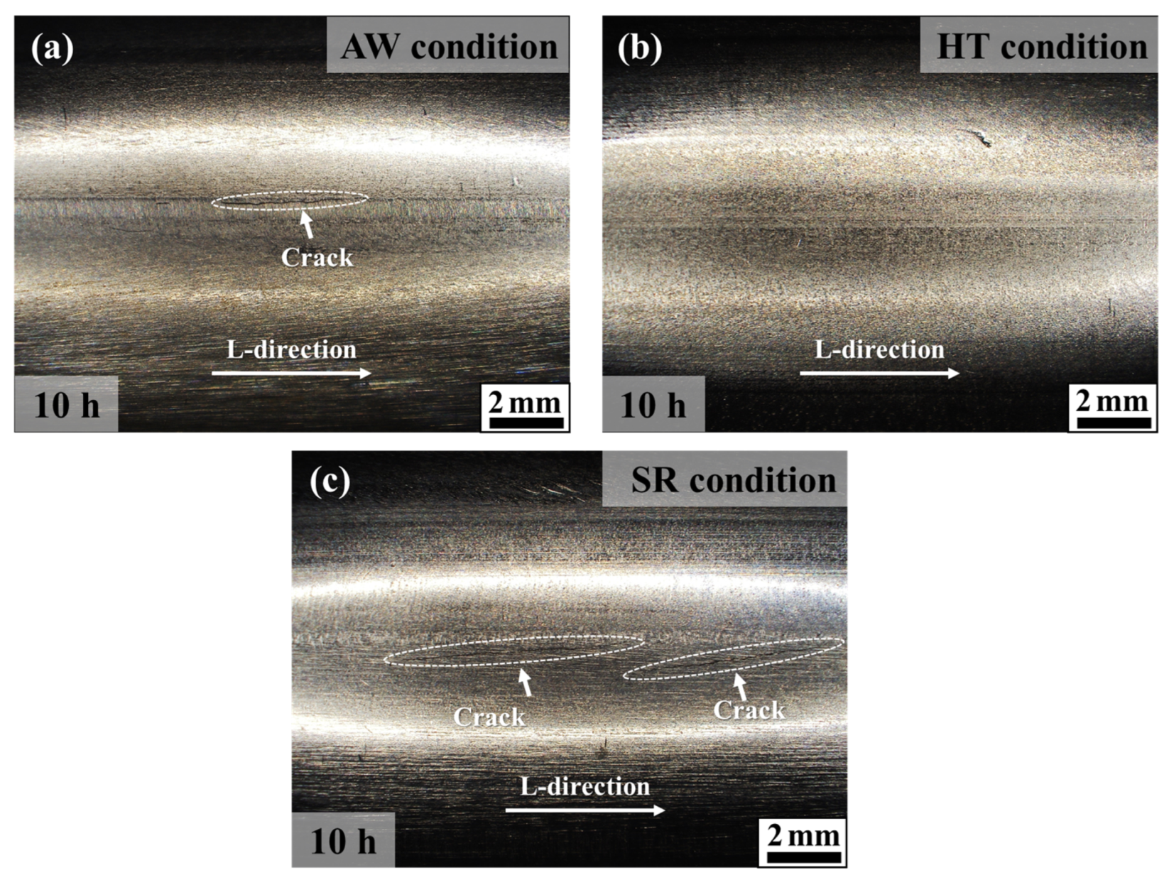
3.4. Evolution of SCC Resistance Depending on the TMP Condition

The observation of crack initiation with exposure time is summarized in Table 3. Longitudinal cracks were found in the AW tubes after 5 h of exposure and in the SR tubes after 10 h of exposure, while no micro-cracks were initiated in the HT tubes within the 10-h exposure period. Figure 4 shows the typical surface morphology of a specimen exposed to boiling MgCl2 solution for 600 min. To analyze the behavior of SCC initiation and propagation, cross-sectional samples were machined from the AW and SR tubes, which exhibited surface cracking. As shown in Figure 5a, one dominant transgranular (TG) crack was observed in the subsurface region. Additionally, a significant amount of martensite and ferrite phases comprising approximately 58 wt.% were present in the overall matrix as well as in the vicinity of the crack. In contrast, cracks in the SR condition exhibited a different morphology; they initiated in a TG form and propagated in an intergranular (IG) mode with branched crack features when they extended in the depth direction, as shown in Figure 5b. Furthermore, compared with the AW condition, a smaller amount of martensite and ferrite phases were formed near the cracks.
The location of crack initiation and the size of the crack are influenced by various factors, including local stress and strain, surface defects, and the microstructure of the metallographic composition [19]. Of these, residual tensile stress is particularly significant in contributing to the initiation of SCC on machined surfaces [4,15]. W. Zhang et al. reported that TG micro-cracks can only be generated when the residual stress reaches a sufficiently high level [19]. In general, TGSCC is initiated from a work-hardened region introduced by machining [4] and cold working [21] of SSs. C. Garcia et al. found that an increased amount of cold work (CW) can transform IGSCC into TGSCC, even in sensitized 304 SS. This transformation occurs due to the formation of deformation bands, which create energetically favorable areas for crack propagation [22]. Therefore, the cracks initiated in the AW and SR tubes are directly influenced by inherent residual stress, and both residual stresses are expected to be larger than the critical stress required for crack initiation.
Microstructural changes also play a dominant role in SCC propagation [13,23]. During the welding process, residual stresses are generally formed in the matrix due to the thermal–mechanical misfit between the base and weld metal [24]; this can result in a large amount of residual stress. Moreover, the stress induces nucleation activation of martensite embryos, leading to lattice deformation [25,26]. The probability of martensite nucleation, denoted as P, can be expressed using the equation [27]:
P Δ G + U ,
where Δ G is the thermodynamically defined Gibbs free energy difference between TMP steps, and U is the external stress applied to the sample. Considering these parameters, stress-induced martensite transformation (SIMT) is favored under elastic deformation when the sum of Δ G + U is greater than the critical energy of formation of martensite ( Δ G c ), ( Δ G + U     Δ G c ) [27,28]. Therefore, in the case of 304L SS, which has low stacking fault energy, deformation tends to evolve from dislocation glide to deformation-induced martensite transformation.
Furthermore, the straightening process—either through stretching or rolling—after solution annealing can also induce residual stress, particularly on the outermost surface. As described above, slip bands and SIMT near the surface (as shown in Figure 6) would act as a higher SCC-susceptible factor. S. Ghosh et al. reported that the presence of a martensitic layer induced by plastic strain contributes significantly to increased susceptibility to SCC [22]. Additionally, the transformation from austenite to martensite weakens the corrosion resistance of the protective oxide film and accelerates the formation of early crack tips [29]. Moreover, the martensitic phase transformation influences residual stress by inducing lattice mismatch [30]. Therefore, the results indicate that the welding and straightening processes can introduce tensile residual stress, and the distribution of critical residual stresses (AW: overall formed high residual stress, HT: small amount of residual stress, SR: locally formed high residual stress) can change significantly depending on the TMP, which can cause the evolution of microstructural features. However, a more accurate determination of the relationship between crack initiation and the magnitude of residual stress requires further studies to provide new insights into crack initiation depending on different levels and distributions of residual stress.

3.5. Effect of Residual Stress and Martensite on SCC Mode

The behavior observed in the SR tube (Figure 5b) indicates that cracks initiate in a TG manner and then transition to IG mode after reaching a certain length. This phenomenon is commonly observed when heavily cold-worked regions are followed by relatively strain-free regions [31]. It is proposed that in cases where a crack initially comes to a stop at a boundary, it can accumulate sufficient potential energy (with a higher concentration of Cl- ions at the crack tip) to promote a new favorable pathway for crack propagation towards a boundary [32]. Furthermore, the residual stress induced by machining and the strain-induced martensite exists primarily in the near-surface zone, as shown in Figure 6. Therefore, the near-surface residual stress does not affect continuous crack propagation in the TG mode [19]. Consequently, this phenomenon suggests that machining-induced residual stress can lead to the manifestation of multiple SCC modes, transitioning from TG to IG when the SCC crack propagates further into the matrix.
In the case of the AW tube, a distinct mode of TG cracking characterized by long and straight cracks is observed when the overall matrix experiences a significant increase in tensile residual stress, surpassing the critical stress required for crack initiation and propagation. It is worth noting that AW tubes exhibit the highest level of residual stress and micro-hardness, irrespective of the radial direction, as discussed in previous sections. Additionally, the presence of a significant amount of SIMT can also significantly influence the SCC mode. Thus, it can be concluded that the occurrence of straight TG cracking in AW tubes is predominantly influenced by high levels of residual stress and the presence of SIMT along the overall matrix.

4. Conclusions

In this research paper, the focus was on investigating SCC resistance and mode under various TMP conditions, taking into account the influence of residual stress and microstructural evolution. Three types of tubes—AW (as-welded), HT (heat treated), and SR (straightened) —were used for the study. Through SCC testing and subsequent analysis, the following conclusions were made:
  • Microstructural changes such as an increase in grain size and grain migration were observed in the HT tube compared with the AW tube. These changes can lead to a significant reduction in hardness and residual stress. Meanwhile, the SR tube exhibited microstructures and mechanical properties similar to those of the HT tube but had slightly higher residual stress and a slight increase in hardness on the outer surface. This could be attributed to surface hardening resulting from the straightening process during manufacturing.
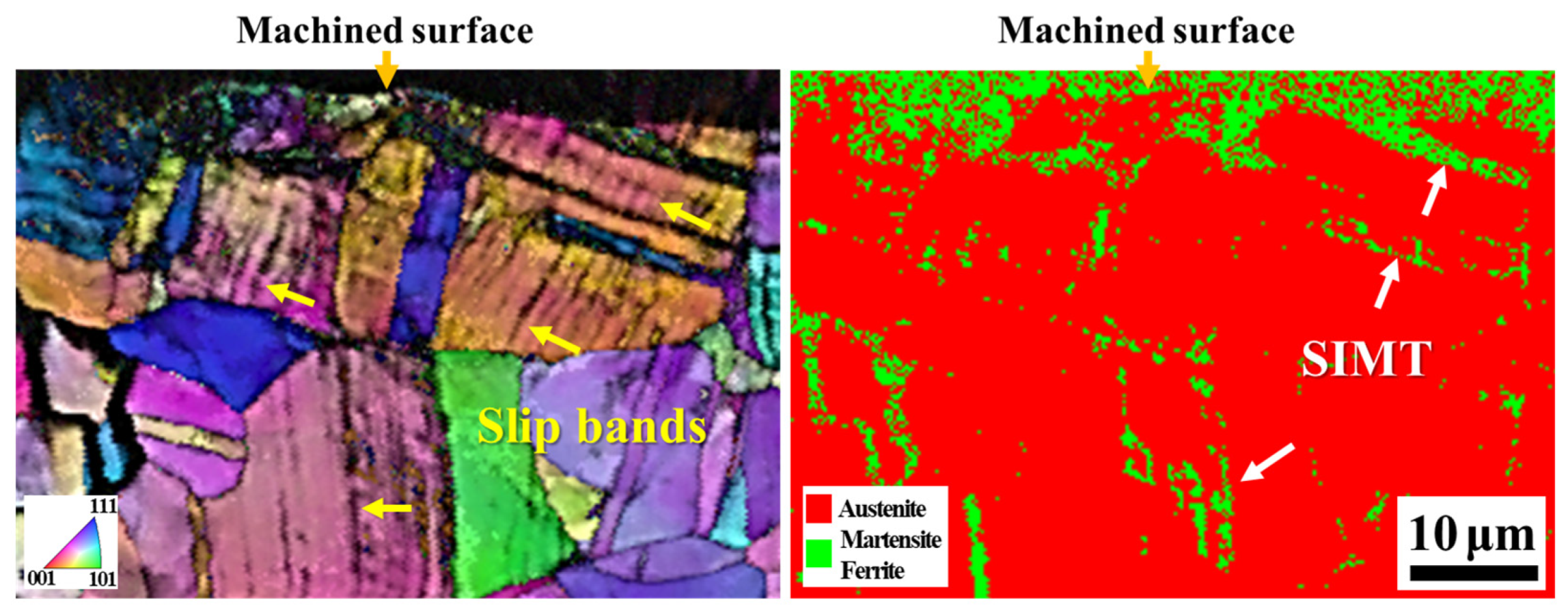
  • TG cracks were found to initiate on the surfaces of AW and SR tubes, which exhibited elevated levels of residual stress and hardness. These regions can be inferred to possess inherent residual stress values that are higher than the critical stress required for crack initiation. Furthermore, the formation of SIMT and slip bands, induced by the TMP, were identified as factors contributing to SCC susceptibility.
  • In summary, varying the TMP condition can lead to variations in the magnitudes of residual stresses and the distribution of slightly different hardness values based on the depth direction, which can be associated with microstructural features. As a result of this, cracks can show multiple SCC modes in cases where residual stress occurs near the surface, while straight TG cracking can be the dominant SCC mode when high levels of residual stress and SIMT occur along the overall matrix.
These findings provide valuable insights into the relationship between SCC behavior, residual stress, and microstructural changes under different TMP conditions.

Funding

This research was supported by Korea Hydro and Nuclear Power Co., Ltd. as the development of stainless steel and Ni-alloy stress corrosion cracking assessment technologies (A19LP18).

Institutional Review Board Statement

Not applicable.

Informed Consent Statement

Not applicable.

Data Availability Statement

The raw/processed data required to reproduce these findings cannot be shared at this time due to technical or time limitations. They will be shared upon request.

Conflicts of Interest

The author declares no conflict of interest.

References

  1. Chen, J.J.; Hsiang Hsieh, I. Using an IR lamp to perform DNA amplifications on an oscillatory thermocycler. Appl. Therm. Eng. 2016, 106, 1–12. [Google Scholar] [CrossRef]
  2. Chang, L.; Volpe, L.; Wang, Y.L.; Burke, M.G.; Maurotto, A.; Tice, D.; Lozano-Perez, S.; Scenini, F. Effect of machining on stress corrosion crack initiation in warm-forged type 304L stainless steel in high temperature water. Acta Mater. 2019, 165, 203–214. [Google Scholar] [CrossRef]
  3. Mayuzumi, M.; Arai, T.; Hide, K. Chloride Induced Stress Corrosion Cracking of Type 304 and 304L Stainless Steels in Air. Zair.-Kankyo 2003, 52, 166–170. [Google Scholar] [CrossRef]
  4. Zhang, W.; Fang, K.; Hu, Y.; Wang, S.; Wang, X. Effect of machining-induced surface residual stress on initiation of stress corrosion cracking in 316 austenitic stainless steel. Corros. Sci. 2016, 108, 173–184. [Google Scholar] [CrossRef]
  5. Fujii, T.; Tohgo, K.; Kenmochi, A.; Shimamura, Y. Experimental and numerical investigation of stress corrosion cracking of sensitized type 304 stainless steel under high-temperature and high-purity water. Corros. Sci. 2015, 97, 139–149. [Google Scholar] [CrossRef]
  6. Bosch, R.W.; Vankeerberghen, M.; Gérard, R.; Somville, F. Crack initiation testing of thimble tube material under PWR conditions to determine a stress threshold for IASCC. J. Nucl. Mater. 2015, 461, 112–121. [Google Scholar] [CrossRef]
  7. Chang, L.; Burke, M.G.; Scenini, F. Understanding the effect of surface finish on stress corrosion crack initiation in warm-forged stainless steel 304L in high-temperature water. Scr. Mater. 2019, 164, 1–5. [Google Scholar] [CrossRef]
  8. Lu, Z.; Shoji, T.; Meng, F.; Qiu, Y.; Dan, T.; Xue, H. Effects of water chemistry and loading conditions on stress corrosion cracking of cold-rolled 316NG stainless steel in high temperature water. Corros. Sci. 2011, 53, 247–262. [Google Scholar] [CrossRef]
  9. Chen, J.; Yang, N.; Nishihara, H. Special issue in honor of Koichi Aoki Preface. J. Electroanal. Chem. 2016, 779, 1–6. [Google Scholar] [CrossRef]
  10. Zhang, L.; Wang, J. Effect of temperature and loading mode on environmentally assisted crack growth of a forged 316L SS in oxygenated high-temperature water. Corros. Sci. 2014, 87, 278–287. [Google Scholar] [CrossRef]
  11. Yaguchi, S.; Yonezawa, T. Intergranular Stress Corrosion Cracking growth perpendicular to fatigue pre-cracks in T–L oriented compact tension specimens in simulated Pressurized Water Reactor primary water. Corros. Sci. 2014, 86, 326–336. [Google Scholar] [CrossRef]
  12. Han, Y.; Mei, J.; Peng, Q.; Han, E.-H.; Ke, W. Effect of electropolishing on corrosion of nuclear grade 316L stainless steel in deaerated high temperature water. Corros. Sci. 2016, 112, 625–634. [Google Scholar] [CrossRef]
  13. Acharyya, S.G.; Khandelwal, A.; Kain, V.; Kumar, A.; Samajdar, I. Surface working of 304L stainless steel: Impact on microstructure, electrochemical behavior and SCC resistance. Mater. Charact. 2012, 72, 68–76. [Google Scholar] [CrossRef]
  14. Turnbull, A.; Mingard, K.; Lord, J.D.; Roebuck, B.; Tice, D.R.; Mottershead, K.J.; Fairweather, N.D.; Bradbury, A.K. Sensitivity of stress corrosion cracking of stainless steel to surface machining and grinding procedure. Corros. Sci. 2011, 53, 3398–3415. [Google Scholar] [CrossRef]
  15. Ghosh, S.; Rana, V.P.S.; Kain, V.; Mittal, V.; Baveja, S.K. Role of residual stresses induced by industrial fabrication on stress corrosion cracking susceptibility of austenitic stainless steel. Mater. Des. 2011, 32, 3823–3831. [Google Scholar] [CrossRef]
  16. Ben Rhouma, A.; Braham, C.; Fitzpatrick, M.E.; Lédion, J.; Sidhom, H. Effects of surface preparation on pitting resistance, residual stress, and stress corrosion cracking in austenitic stainless steels. J. Mater. Eng. Perform. 2001, 10, 507–514. [Google Scholar] [CrossRef]
  17. Park, J.W.; Ferracane, J.L. Measuring the residual stress in dental composites using a ring slitting method. Dent. Mater. 2005, 21, 882–889. [Google Scholar] [CrossRef]
  18. Seif, M.; Short, S. Determination of residual stresses in thin-walled composite cylinders. Exp. Tech. 2002, 26, 43–46. [Google Scholar] [CrossRef]
  19. Zhang, W.; Wang, X.; Wang, S.; Wu, H.; Yang, C.; Hu, Y.; Fang, K.; Jiang, H. Combined effects of machining-induced residual stress and external load on SCC initiation and early propagation of 316 stainless steel in high temperature high pressure water. Corros. Sci. 2021, 190, 109644. [Google Scholar] [CrossRef]
  20. Zhang, W.; Wang, X.; Hu, Y.; Wang, S. Predictive modelling of microstructure changes, micro-hardness and residual stress in machining of 304 austenitic stainless steel. Int. J. Mach. Tools Manuf. 2018, 130–131, 36–48. [Google Scholar] [CrossRef]
  21. Nakano, J.; Nemoto, Y.; Tsukada, T.; Uchimoto, T. SCC susceptibility of cold-worked stainless steel with minor element additions. J. Nucl. Mater. 2011, 417, 883–886. [Google Scholar] [CrossRef]
  22. Hou, Z.; Xiu, S.; Sun, C.; Zou, X.; Yao, Y. Enhancing the surface integrity and SCC resistance of 304 austenitic stainless steel by pre-stress grinding. J. Mater. Res. Technol. 2023, 25, 2890–2902. [Google Scholar] [CrossRef]
  23. Motoyashiki, Y.; Brückner-Foit, A.; Sugeta, A. Microstructural influence on small fatigue cracks in a ferritic–martensitic steel. Eng. Fract. Mech. 2008, 75, 768–778. [Google Scholar] [CrossRef]
  24. Liu, Y.; Wang, L.; Song, X.; Liang, T. Microstructure and high-temperature deformation behavior of dissimilar superalloy welded joint of DD407/IN718. Acta Met. Sin. 2019, 55, 1221–1230. [Google Scholar]
  25. Stringfellow, R.; Parks, D.; Olson, G. A constitutive model for transformation plasticity accompanying strain-induced martensitic transformations in metastable austenitic steels. Acta Metall. Mater. 1992, 40, 1703–1716. [Google Scholar] [CrossRef]
  26. Olson, G.; Cohen, M. Kinetics of nucleation strain-induced martensitic. Metall. Mater. Trans. A 1975, 6, 791. [Google Scholar] [CrossRef]
  27. Han, H.N.; Lee, C.G.; Oh, C.-S.; Lee, T.-H.; Kim, S.-J. A model for deformation behavior and mechanically induced martensitic transformation of metastable austenitic steel. Acta Mater. 2004, 52, 5203–5214. [Google Scholar] [CrossRef]
  28. Shen, Y.; Li, X.; Sun, X.; Wang, Y.; Zuo, L. Twinning and martensite in a 304 austenitic stainless steel. Mater. Sci. Eng. A 2012, 552, 514–522. [Google Scholar] [CrossRef]
  29. Zhou, N.; Lin Peng, R.; Pettersson, R.; Schönning, M. Residual stress in stainless steels after surface grinding and its effect on chloride induced SCC. In Proceedings of the International Conference on Residual Stresses, Sydney, Australia, 3–7 July 2016; pp. 289–294. [Google Scholar]
  30. Ghosh, S.; Kain, V. Microstructural changes in AISI 304L stainless steel due to surface machining: Effect on its susceptibility to chloride stress corrosion cracking. J. Nucl. Mater. 2010, 403, 62–67. [Google Scholar] [CrossRef]
  31. Okamura, Y.; Sakashita, A.; Fukuda, T.; Yamashita, H.; Futami, T. Latest SCC issues of core shroud and recirculation piping in Japanese BWRs. In Proceedings of the SMIRT 17: 17. International Conference on Structural Mechanics in Reactor Technology, Prague, Czech Republic, 17–22 August 2003. [Google Scholar]
  32. Ohaeri, E.; Eduok, U.; Szpunar, J. Hydrogen related degradation in pipeline steel: A review. Int. J. Hydrog. Energy 2018, 43, 14584–14617. [Google Scholar] [CrossRef]
Figure 1. Cross-sectional OM micrographs of the AW (ac), HT (df), and SR (gi) conditions. High-magnification OM images of the weld region (a,e,h) and the section opposite the weld region (c,f,i).
Metals 13 01458 g001aMetals 13 01458 g001b
Figure 2. OM micrographs of splitting distances on the outer surfaces of the (a) AW, (b) HT, and (c) SR tubes. (d) The splitting distance of the width of the cutting wire (~330 μm).
Metals 13 01458 g002
Figure 3. Results of micro-hardness test for As-welded, Heat treated, and Straightened conditions along the radial direction.
Metals 13 01458 g003
Figure 4. Typical surface morphologies of (a) AW, (b) HT, and (c) SR tubes after SCC test in boiling MgCl2 solution for 600 min.
Metals 13 01458 g004
Figure 5. EBSD results of cross-sectional (a) AW and (b) SR tubes after SCC test in boiling MgCl2 solution for 600 min. IPF map (left) showing crystal orientation changes and phase map displaying the distribution of austenite and martensite/ferrite phases. The boxed region in (b) was analyzed further and shown in Figure 6.
Metals 13 01458 g005
Figure 6. High magnification IPF and phase maps of the SR tubes from Figure 5. Slip bands and SIMT are indicated.
Metals 13 01458 g006
Table 1. Thermo-mechanical processing conditions, measured grain size, and grain migration features between the weld and base metals.
TMP ConditionThermo-Mechanical ProcessingGrain Size
(μm)
Grain Migration between the
Weld and Base Metals
WeldingHeat Treatment TemperatureStraightening
AW--22 ± 4×
HT1050 °C-68 ± 23
SR1050 °C71 ± 21
Table 2. Residual stress, modulus of elasticity, inner and outer radius of tube, radius of ring thickness, displacement in width after splitting, splitting distance, splitting distance except wire width, and residual stress for split-ring specimens.
TMP Condition M r
( GPa · m m 2 )
E
(GPa)
a
(mm)
b
(mm)
r
(mm)
δ
(mm)
Splitting Distance
(μm)
Splitting
Distance Except Wire Width
(μm)
Residual Stress
(MPa)
AW−7664.81906.757.957.3510431373 ± 4710431219
HT−1609.41906.757.957.35219549 ± 7219256
SR−2461.91906.757.957.35335665 ± 34335391
Table 3. Results of crack initiation under the three TMP conditions in boiling MgCl2 solution.
TMP ConditionExposure Time
2.5 h5 h7.5 h10 h
AW tubes-Observation of crackingObservation of crackingObservation of cracking
HT tubes----
SR tubes---
Disclaimer/Publisher’s Note: The statements, opinions and data contained in all publications are solely those of the individual author(s) and contributor(s) and not of MDPI and/or the editor(s). MDPI and/or the editor(s) disclaim responsibility for any injury to people or property resulting from any ideas, methods, instructions or products referred to in the content.

