Article

A Preliminary Study of New Experimental Low-Cost Fe–P-Based and Mn–Fe–P-Based Brazing Filler Metals for Brazing of Non-Alloy and Low-Alloy Steels

1
Department of Materials and Metallurgy, Faculty of Natural Sciences and Engineering, University of Ljubljana, Aškerčeva 12, 1000 Ljubljana, Slovenia
2
Welding Institute Ltd., Ptujska 19, 1000 Ljubljana, Slovenia
*
Author to whom correspondence should be addressed.
Metals 2023, 13(9), 1513; https://doi.org/10.3390/met13091513
Submission received: 20 July 2023 / Revised: 16 August 2023 / Accepted: 22 August 2023 / Published: 24 August 2023
(This article belongs to the Section Welding and Joining)

Abstract

:
Seventeen new experimental filler metals from eight different alloy systems based on Fe–P–X and Mn–Fe–P–X (X = B, C, Si in various combinations) were created and experimented with. DSC analyses were performed to determine the solidus and liquidus temperatures and the melting ranges. Hardness measurements of the alloys were performed in the as-cast state. The alloys contain primary and eutectic intermetallic compounds that make them very hard with average hardness values ranging from 590 HV10 to 876 HV10. The wettability was determined at 1000 °C, 1040 °C and 1080 °C on C22 non-alloy steel and 15CrNiS6 low-alloy steel in Ar 4.6 and 78 vol% H2-22 vol% N2 atmospheres. The results show good wettability at T = 1080 °C in both atmospheres, as the contact angles were mostly ≤30°. Thirteen alloys exhibit very good wettability with average contact angles of ≤15.5°. Nine alloys exhibit excellent wettability with their average contact angles being ≤10°. Wettability improves at higher temperatures. The liquid alloys are reactive to solid steels and form a diffusion joint. Diffusion of P, B, C, and Si from the filler metal into the base material dealloys the composition of the melt near the joint interface. For the same reason, a continuous layer of solid solution forms on the joint interface. When brazing with filler metals rich in carbon, strong carburisation of steels can be observed near the joint.

1. Introduction

Brazing has been used since the 1950s as a means of fabricating structures for aerospace, nuclear, and other applications [1]. Even before that, it was used for certain industrial applications. For example, brazing of low-carbon steel components with a copper alloy had been known since the 1930s [1]. Iron-based filler metals first appeared in the scientific literature in the 1970s [2]. They later emerged as a substitute for the more expensive nickel, with the Ni content decreasing to the point where it was replaced by iron as the base element, creating a whole new group of Fe-based stainless brazing alloys.
The first paper on the development of iron-based filler metals for joining molybdenum components in certain nuclear reactors and chemical processing systems was presented in 1971 by Cole N. C. et al. and included four iron-based alloys: Fe4C1B, Fe15Mo4C1B, Fe25Mo4C1B, and Fe15Mo5Ge4C1B [2]. In the 1980s, three patents were filed with the United States Patent and Trademark Office. First, in 1983, patent 4,402,742 was filed by Pattanaik S., who sought to solve the problem of rising nickel prices by creating an Fe-based filler metal with a composition influenced by stainless steels. Different alloys of Fe–Ni–Si–B and Fe–Ni–Cr–Si–B alloy systems were produced and tested [3]. This was the first time that filler metals with compositions similar to stainless steel can be found in the literature. Various chemical compositions based on Fe–Cr and Fe–Ni–Cr now represent the largest proportion of Fe-based filler metals in engineering and the scientific literature. Another patent was filed in 1983 by Pohlman M. J. et al. showing the production of Fe–Si–B, Fe–Cr–Si–B, Fe–Ni–Cr–B–C, and, finally, Fe–Ni–Cr–Si–B with up to 0.02 wt% C and 0.07 wt% Ti. Two other alloys from the Fe–Ni–Cr–Si–Mn–B system with up to 0.02 wt% C were produced [4]. In 1985, a patent was filed by Coad B. C. claiming the production of Fe–Ni–Cr–Si–B, Fe–Cr–Si–B–Mo, Fe–Cr–Mn–Ni–Si–B, Fe–Cr–Si–B, and Fe–Cr–Ni–Si–B brazes [5]. Fe–B–Si amorphous filler metal with 13.0 wt% B and 9.0 wt% Si was used for transient liquid phase bonding in 1993 [6]. Six compositions of Fe–Si–B-based filler metal were used in 1995 [7]. The 1995 Löttechnik handbook lists possible iron-based filler metals as follows: ferromanganese, ferrosilicon, cast iron with about 4.3 wt% C, and, finally, iron-based alloys with addition of chemical elements such as C, Mn, Si, B, Mo, Cu, Co, W, Al, Nb, Ti, and Ge [8]. Fe–Ni–B was mentioned for the first time in 1998, together with Fe–Ni–Si–B, which had already been previously mentioned in the scientific literature [9]. In the 21st century, there was not a lot of development on new alloy systems, with most merely modifying the compositions of existing filler metals, such as Fe–B–Si- and Fe–Cr–B–Si-based alloys [10,11,12]; Fe–Cr-based alloys with additions of Co and/or Ni, W, Mo as well as B and Si [13]; Fe–Cr-based alloys with addition of Si and P [14]; Fe–Cr-based alloys with addition of P and B [15]; Fe–Ni-based filler metals with addition of Mo and B [16]; and Fe–Ni–Cr-based filler metals in various combinations with other alloying elements and a combination of melting point depressants B, Si, P, and C [17,18,19,20,21,22,23,24,25,26,27,28,29,30]. New developments in this period are Fe–Al–Si and Fe–Al–Si–Mo filler metals for brazing iron aluminides [31] and Fe–Ni-based filler metal with between 10.0 wt% and 20.0 wt% of a combination of melting point depressants C, P, Si, and B [32].
Manganese-based brazing filler metals are much less common in the scientific literature and in practice. They were first mentioned in a 1959 patent claiming an Mn-based filler metal consisting of Mn, Ni, rare earth metals, and a combination of Zr, Hf, and Ti [33]. Another patent was filed in 1964 claiming an invention of Mn–Ni-based filler metal with optional addition of Co and/or Cu and/or mischmetal [34]. The ASM Source Book on Brazing and Brazing Technology mentions Mn–30Ni and Mn–16Ni–16Co–1B filler metals sourced from the WRC Bulletin 187 of 1973 [1]. Other Mn-based filler metals found in the scientific literature are Mn–27.5Ni–13.5Cu–4.5Cr–4.5Co (wt%) for brazing FeCrMo damping alloys [35] and 70Mn–25Ni–5Cr (wt%) for brazing directionally solidified superalloys based on intermetallic Ni3Al compounds [36], as well as stainless steel [37,38].
In recent years, there have been some studies on high-entropy alloys that have been used as brazing filler metals or that may be useful for future research on this topic. Such alloys may contain Fe [39,40,41,42] and/or Mn [41,42]. However, these filler metals cannot be classified as either iron-based or manganese-based, since one of their characteristics is an approximately equimolar composition of all constituent chemical elements.
The brazing alloy must have a lower melting point than the base material, so certain chemical elements known as melting point depressants may be added to filler metals. In Ni-based and Fe-based brazing alloys, these elements are usually boron and silicon, sometimes phosphorus, and rarely carbon in various combinations and concentrations. These chemical elements tend to form intermetallic phases in the microstructure, making the filler metals hard and brittle [1,43]. The microhardness values in the brazed joint reach values from about 400 HV to 750 HV [19,21,22,44].
One of the most important properties of brazing filler metals is their wettability. This property causes the filler metal to flow and spread on the base material. Several factors affect wettability: the chemical composition of the filler metal, the condition of the surface of the base material, the filler material—base material combination, the brazing temperature and time, the type of flux, and the type and purity of the atmosphere. The most important factors are the chemical composition of the filler metal and cleanliness of surfaces of both the filler and the base material. The contribution of other factors to the wettability and the consolidation of the filler and base material will be greatly reduced if these two conditions are not met.
Good wettability is generally attributed to a narrow melting range of a filler metal, which is narrowest near the eutectic compositions [43]. A wide melting range of non-eutectic alloys extends the time the filler metal spends in its dual phase (liquid + primary phase) region of the phase diagram during heating and cooling. Since the alloy is not yet fully molten when it starts spreading, its flow is slower compared to eutectic alloys, which melt immediately upon reaching their melting temperature. Liquation also tends to occur in filler metals with wide melting ranges. The contact angle can be measured from a drop on the surface of the base material or from a braze fillet [43,45]. For most brazing systems, the optimum value of the contact angle is in the range of 10° to 45° [45].
In our research, we produced and characterised new experimental brazing filler metals based on Fe–P and Mn–Fe–P with additions of B, C, and Si in various combinations. Some properties of the brazing alloys and their potential usefulness for brazing of non-alloy and low-alloy steels were determined.

2. Materials and Methods

2.1. Experimental Alloys

A total of 5 kg of each alloy was produced in a powerline-frequency induction furnace with aluminate lining. The alloys were prepared from different raw materials, such as ferroalloys FeP (17.65 wt% P), FeB (17.0 wt% B), FeSi (80 wt% Si), FeMn LC (80 wt% Mn), S235 steel, pure iron, and carbon for nodular cast iron. Ar 4.6 grade was blown onto the melt. The alloys were cast into a preheated (T = 100 °C) vertical grey cast iron permanent moulds with dimensions: 40 mm × 20 mm × 300 mm. The walls were 22 mm, 25 mm, and 32 mm thick and coated with zirconia. A total of 17 alloys were produced from 8 different alloy systems. In some of them, only one composition was made, while in others, there were several compositions made to achieve the desired material properties.

2.2. Wettability Samples

The wettability was determined from the contact angles of the drops on the base materials. The samples for the wettability tests were taken from the castings, which were broken into smaller fragments of various sizes (0.5 mm3–5 mm3). These were placed on the plates of ferritic-pearlitic C22 non-alloy steel (C = 0.18–0.25; Si = 0.15–0.4; Mn = 0.4–0.7; P ≤ 0.045; S ≤ 0.045; in wt%) as well as quenched and tempered low-alloy steel 15CrNiS6 (C = 0.14–0.19; Si = 0.15–0.4; Mn = 0.4–0.6; P ≤ 0.035; S ≤ 0.035; Cr = 1.4–1.7; Ni = 1.4–1.7; in wt%). The volume of the filler metal pieces ranged from 5 mm3 to 8 mm3. The base metal plates were round, 30 mm in diameter, and 5 mm thick with parallel surfaces; they were cut from steel rods. The surfaces of both the steel plates and the filler metals were ground with an #80 grit SiC abrasive paper prior to heating to remove possible surface oxides. The wettability tests were performed in a tube furnace with an inert Ar 4.6 atmosphere and in an industrial conveyor belt furnace with an active atmosphere consisting of a mixture of 78 vol% H2–22 vol% N2 (hereafter referred to as H2–N2). The high H2 content makes this mixture a reducing one for a large number of metal oxides. However, the nitrogen it contains can in some cases make it an oxidising atmosphere towards certain chemical elements in the filler metals, which react with it to form nitrides. One such chemical element is boron. The dew point TDP of the atmospheres was not measured, but the requirement for an H2–N2 atmosphere in industry is TDP < −60 °C, which is also a requirement for an inert atmosphere [1]. The brazing temperatures were set according to the heating curves of the DSC analyses of the experimental filler metal alloys. When the alloys melted, they formed a drop on the surface of the base metal whose contact angle was measured (Figure 1). At least four measurements were made for each alloy.
All alloys were tested in an argon and H2–N2 mixture at T = 1080 °C on a C22 steel plate. The temperatures of the samples were monitored with a type K thermocouple. The samples tested in an argon atmosphere were placed in an already heated furnace, which was calibrated prior to each experiment. The samples were closely monitored to determine the exact time of melting. After melting, they were left in the furnace for an additional 5 min before being carefully removed from the heating area and cooled in Ar. Throughout the experiment, the Ar pressure in the tube was maintained at p = 1.8 bar to prevent air from flowing into the tube. The experiments in the H2–N2 atmosphere were performed at T = 1080 °C in an industrial environment during the manufacturing process of the brazed products. For this reason, brazing could not be performed at lower temperatures. The conveyor belt furnace has a preheating zone (T ≈ 200 °C), three high-temperature zones for brazing, and a cooling zone. The speed of the conveyor belt was set to v = 0.07 m/min. The samples were heated to the brazing temperature in t = 15 min. In total, they spent about t = 5 min at T = 1080 °C and about t = 16 min above T = 1000 °C. For example, the specimen brazed with the Mn–Fe–P–C alloy, which has the lowest solidus temperature of all the alloys (TS = 918 °C), spent t = 18 min above its TS.
Following this experiment, seven alloys were selected. The criteria considered included DSC analyses and wettability test results on C22 steel. The properties used to determine the suitability of the alloys from DSC analyses were narrow melting ranges with the lowest possible solidus and liquidus temperatures. Another property considered was the shape of the DSC heating curve, as alloys with very pronounced low-temperature peak(s) are best suited for brazing. This type of DSC heating curve shows that most of the alloy has already melted at a temperature lower than its TL. The selected alloys were brazed onto the C22 and 15CrNiS6 steels in argon atmosphere at temperatures T = 1000 °C, 1040 °C, and 1080 °C.

2.3. Research Methods

The chemical compositions of filler metal alloys were determined using the ICP OES method and carbon combustion (Eltra combustion technique device). A NETZSCH STA 449 C Jupiter instrument (NETZSCH, Selb, Germany) was used to perform DSC analyses of the alloys to determine their melting ranges. The heating and cooling rates were 10 °C/min. The samples for DSC analysis were taken from the center of the central part of the casting, as average solidification conditions are expected at this location. Microscopic examination of the bulk filler alloys was carried out using the Leitz Laborlux 12 light microscope ME (Ernst Leitz GmbH, Wetzlar, Germany). The metallographic specimens were wet ground with SiC abrasive paper with a grit size of up to #2400 and polished with a diamond paste with a grit size of 1 μm. The samples were etched with a 4% nital. The hardness HV10 of the bulk filler alloys was measured according to the standard EN ISO 6507-1:2018 [46] using the Swiss Max 300 hardness tester (Gnehm Härteprüfer AG, Thalwil, Switzerland). Ten measurements were performed on each alloy. The average HRC values are also given. Due to the intermetallic phases in the microstructure, the HRC values are determined comparatively from the table for Cr-alloyed white cast iron [47]. The values are approximate because the HV→HRC converters are different for the different materials [47,48].
Wettability was determined from the contact angles of the drops on the base materials. The wettability samples were cut through the center of the drop perpendicular to the edge of the drop, while also taking into account the width of the blade and the material removal due to metallographic preparation. This ensured that the tested surface was indeed perpendicular to the edge of the drop and that the measured contact angles were correct. The samples were prepared metallographically as described in the previous paragraph. The contact angles were measured as shown in Figure 1c.

3. Results and Discussion

3.1. Compositions and Properties of Experimental Alloys

Table 1 contains the chemical compositions and melting ranges of the alloys produced in the rapidly cooled, as-cast state in the permanent mould. The melting ranges TS-L were determined using the data acquired from the heating and cooling curves of the DSC analyses.
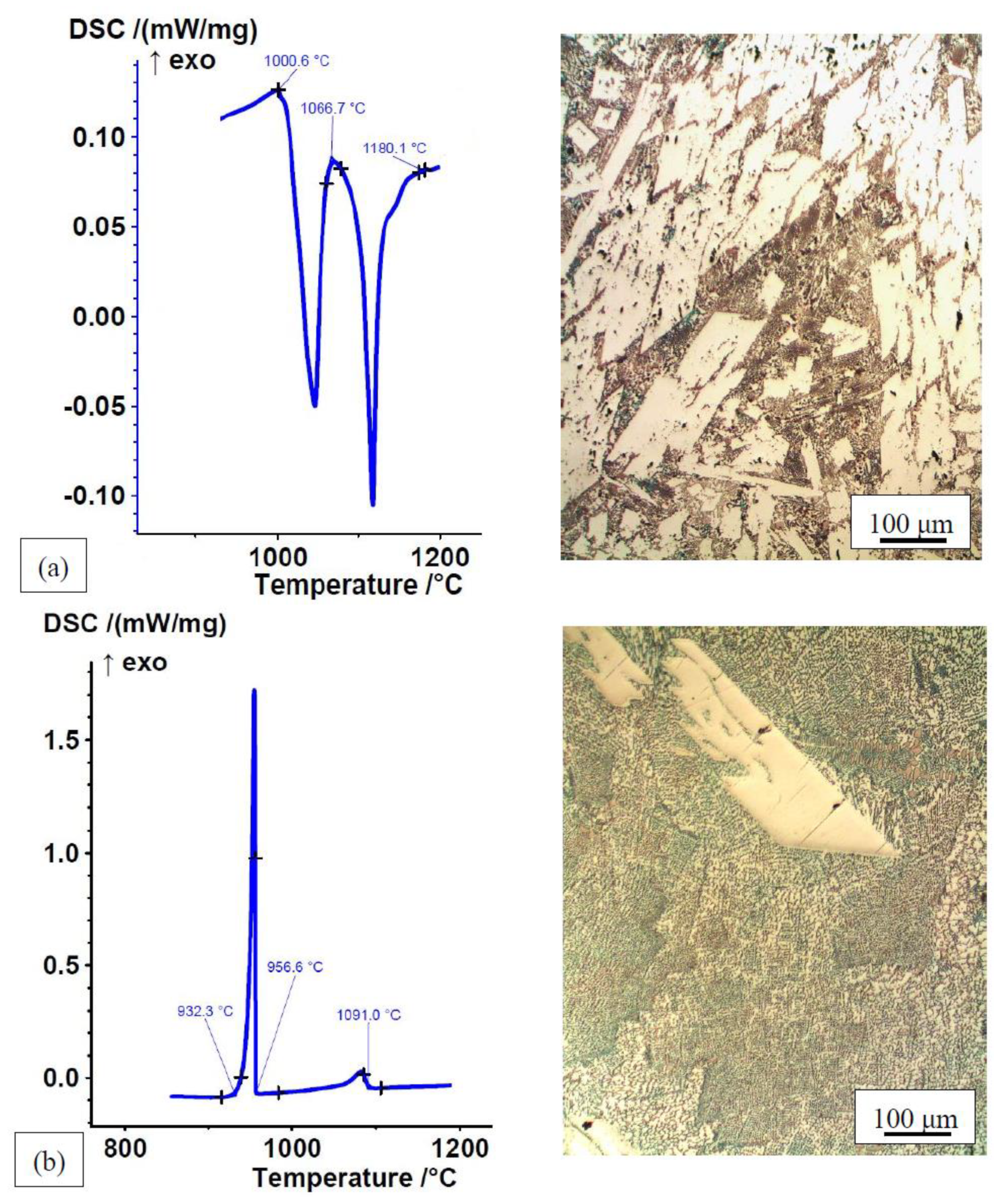
The transformation temperatures of the alloys in the rapidly cooled, as-cast state in the permanent mould are slightly higher than those of the homogenized and slowly cooled DSC samples. The formation of non-equilibrium microstructural constituents in rapidly cooled multicomponent alloys causes their DSC heating curves to deviate from the cooling curves of the already homogenized and slowly cooled melt with an equilibrium microstructure and causes them to be less pronounced (Figure 2 and Figure 3). During heating, individual non-equilibrium transformations may coalesce with prior lower-temperature transformations. This is a consequence of the simultaneous homogenisation, dissolution of the individual non-equilibrium phases, and melting of the alloy during the heating phase of the DSC analysis. Therefore, the amount and size of the endothermic peaks do not necessarily correspond to the amount and quantity of the individual microstructural constituents (Figure 3). The most applicable melting range of the alloys is defined by the DSC cooling curves. The microstructures of the alloys consist of eutectics (solid solution + intermetallic phase) and primary intermetallic compounds. Non-equilibrium microstructural constituents (primary intermetallic phases and eutectics) in the alloys that were rapidly cooled and solidified in the mould are smaller than the equilibrium microstructural constituents of the slowly cooled and solidified samples. The contents of the individual microstructural constituents are also different (Figure 2 and Figure 3). The amount and size of the peaks on the heating and cooling curves of Fe–P–B (1) alloy are consistent with its microstructure. Since the proportion of eutectic (a lower-temperature peak) and primary intermetallic phase (a higher-temperature peak) in the non-equilibrium microstructure is approximately equal, both endothermic peaks look similar. The equilibrium microstructure consists of a much higher eutectic content, which makes the exothermic lower-temperature peak much larger.
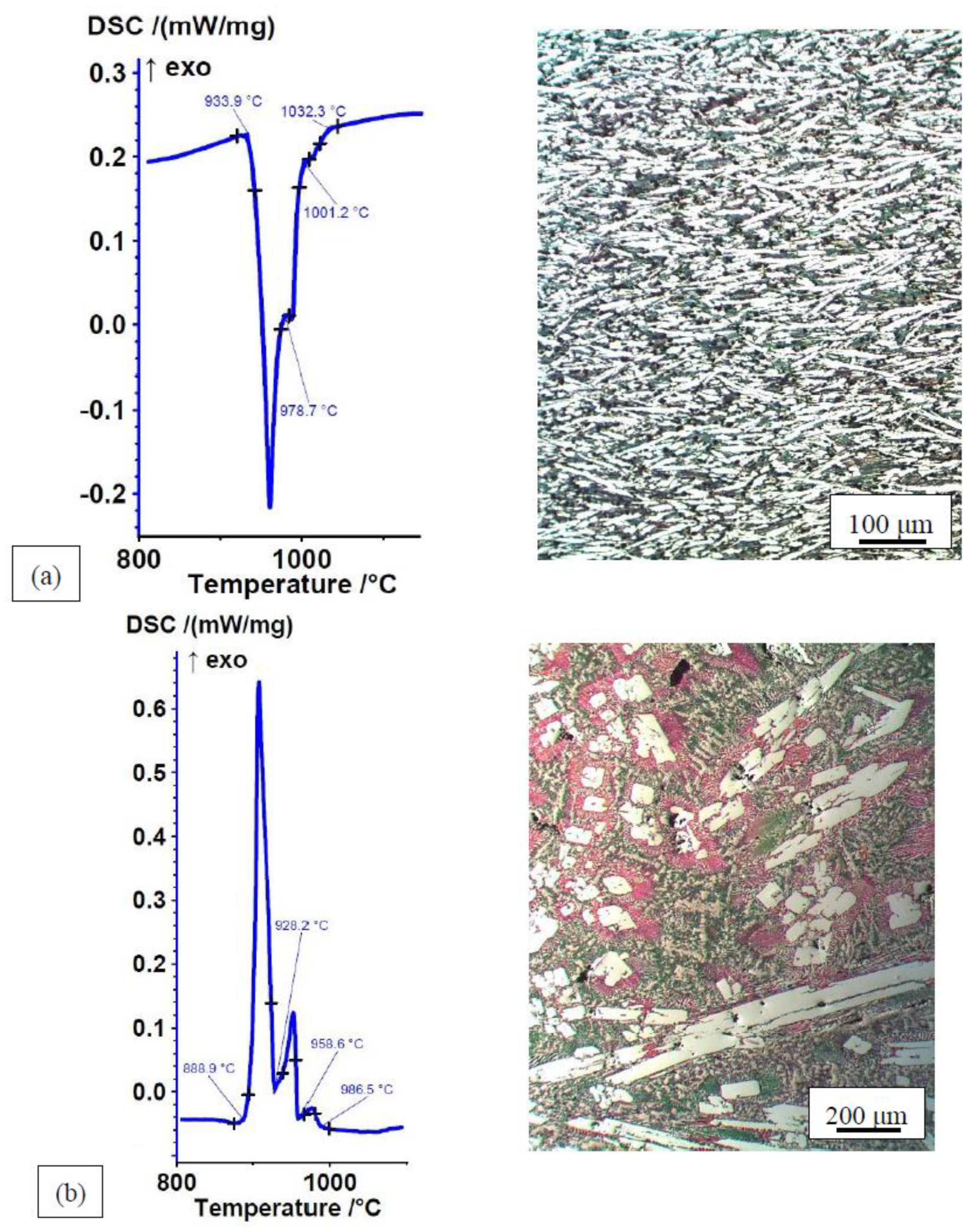
A different situation may be observed in the Mn–Fe–P–B (3) alloy. The non-equilibrium microstructure is fine-grained and consists of three evenly distributed constituents See Figure 3a: eutectic (blue), pointed intermetallic phase (white), and solid solution (brown polygonal crystal grains). The proportion of eutectic and intermetallic phase in the microstructure is similar. However, this is not reflected in the DSC heating curve. There is only one strongly pronounced lower-temperature endothermic peak, which belongs to the eutectic. Based on the microstructure, the two higher-temperature peaks should also be strongly pronounced. This is a consequence of the already described simultaneous processes of homogenisation, dissolution, and melting of the non-equilibrium phases during the heating phase of the DSC analysis. It appears that the alloy already strives for the equilibrium state during melting by forming a large amount of eutectic. The DSC cooling curve with three exothermic peaks is consistent with the equilibrium microstructure, which is completely different from the non-equilibrium microstructure. It consists of a primary intermetallic phase (white fields; higher-temperature peak), a binary eutectic (pink lamellar regions around the white intermetallic phases; middle peak), and a ternary eutectic (bluish-light brown base; strongly pronounced lower-temperature peak).
The aim of this research was to create alloys characterised by liquidus temperatures of less than TL ≈ 1100 °C, narrow melting ranges, and the lowest possible solidus temperatures TS. Eleven of the produced alloys already fulfil the requirements in the non-homogenised state, while thirteen of them fulfil the requirements in the homogenised state (Table 1). TS and TL temperatures as well as melting ranges of most of the produced alloys are similar to those of commercial and experimental Ni-based and Fe-based brazing alloys [3,8,12,13,19,23,26,31,32,45,50].
All the produced alloys are very hard and brittle (Table 2) [49]. This was to be expected due to the presence of primary and eutectic iron-based and manganese-based intermetallic phases such as phosphides, borides, carbides, and silicides. However, this does not mean that the produced alloys cannot be used as brazing filler metals. Brittleness and high hardness are a feature of all known Ni-based and Fe-based brazing filler metals containing P, B, Si, and C.

3.2. Wettability

The effects of controlled atmosphere, brazing temperature, and base material on the wettability of the experimental alloys were analysed. The contact angles of all seventeen alloys on C22 carbon steel at T = 1080 °C in Ar 4.6 and H2–N2 atmospheres are shown in Table 3.
Considering the acceptable wettability of brazing filler metals, defined as θ ≤ 45°, all the produced alloys show good wettability on C22 steel at T = 1080 °C in both atmospheres. Their contact angles are generally θ < 30°. A very good wettability with contact angles θ ≤ 15.5° was observed in thirteen alloys. Nine alloys exhibited excellent wettability with average contact angles θ ≤ 10°. The smallest contact angles were measured in the Fe–P alloy. The alloys show better wettability in an inert Ar 4.6 atmosphere. Manganese-based alloys tend to have worse wettability than iron-based alloys. The explanation for this phenomenon could be a strong tendency of manganese to oxidise and consequently a higher sensitivity to small differences in the content of atmospheric impurities, such as water vapour and oxygen [45].
Of the seventeen alloys, only Fe–P–C–B (2) and Fe–P–C–B (3) did not melt in H2–N2 atmospheres. Nevertheless, they wet the non-alloy steel very well in an argon atmosphere. The most likely reasons for this are their high boron content, their high liquidus temperatures, and their wide melting ranges. According to DSC analyses, Fe–P–C–B (2) and Fe–P–B–C (3) alloys start melting at TS = 956 °C and are only completely molten at TL = 1189 °C and 1212 °C, respectively. Some microstructural constituents therefore melt quickly while there are still other solid phases present at the same time. The small amount of molten filler metal could therefore not be able to spread, as it reacts with N2 from the atmosphere and forms solid nitrides before other phases even have time to melt. Boron nitrides could also be responsible for the, on average, twice as large contact angles in a H2–N2 atmosphere compared to those in an Ar atmosphere in boron containing Mn–Fe–P–B alloys. It is clear that an increased amount of boron worsens the wettability in a H2–N2 atmosphere, as a larger amount of boron nitride is formed on the surface of the molten alloy. The wettability of Fe–P–C–B and Mn–Fe–P–B alloys in Ar is practically identical. There is an anomaly in the case of Fe–P–C–B (1) and Fe–P–C–B (4) alloys, whose contact angles are smaller in H2–N2 atmospheres. These alloys have two to three times lower boron content (0.74 wt% and 1.3 wt%, respectively) and a much narrower melting range than Fe–P–C–B (2) and Fe–P–C–B (3) alloys, which did not melt in a H2–N2 atmosphere. This anomaly could be explained by their narrow melting ranges and associated faster melting, which enhances the effect of reductive H2 and negates the effect of N2. Regardless, the slightly poorer wettability of the two alloys in Ar atmosphere is not important in practice, as the contact angles in both atmospheres are very small. It appears that when brazing in a H2–N2 atmosphere, the adverse effect of boron in Fe–P–C–B and Mn–Fe–P–B alloys is greatly reduced by the narrowness of the melting range.
There is also an interesting case of Fe–P–B (1) and Fe–P–B (2) alloys, which have spread very well in both atmospheres, even though their liquidus temperatures are as high as 1180 °C and 1220 °C, respectively. The reason for this becomes clear when looking at the DSC heating and cooling curves of Fe–P–B (1) alloys (Figure 2). Taking into account the simultaneous processes of homogenisation, dissolution, and melting of non-equilibrium phases during heating, it can be clearly seen on the heating curve that a majority of the alloy has already melted before reaching the brazing temperature of 1080 °C. The remainder either stayed solid or has dissolved and homogenised in the melt during brazing, aiding in the spreading of the filler metal and providing good wettability. The cooling curve shows an already homogenised material having a much lower liquidus temperature of TL = 1091 °C (Figure 2) than the same material in a rapidly cooled, as-cast state. The same was observed in all alloys, as the non-equilibrium primary phases are replaced by an equilibrium microstructure, consisting of a larger quantity of the eutectic, lowering the TL of the alloys (Figure 3). Homogenised filler metals therefore have a lower TL than in the rapidly cooled, as-cast state in which they were analysed and used for brazing.
Based on an optimal combination of wettability, microstructure, solidus and liquidus temperatures, as well as melting ranges, seven alloys were selected to conduct further wettability experiments: Fe–P, Fe–P–B (3), Fe–P–C, Fe–P–C–B (4), Mn–Fe–P, Mn–Fe–P–B (3), Mn–Fe–P–Si (3). Their microstructures and DSC heating curves in the rapidly cooled, as-cast state are shown in Figure 4 (Mn–Fe–P–B (3) was shown in Figure 3).
The non-equilibrium microstructure of Fe–P–B (3) and Mn–Fe–P alloys consists of a eutectic (solid solution + intermetallic compound) and small individual solid solution crystal grains. The non-equilibrium microstructure of other alloys consists of a eutectic (solid solution + intermetallic compound) and a greater or lesser content of primary intermetallic compounds. DSC analyses have shown that these alloys have completely melted before reaching the brazing temperature T = 1080 °C. The effect of the atmosphere on the wettability of selected alloys on 15CrNiS6 low-alloy steel is shown in Table 4.
The results show good wettability of the selected filler metals on 15CrNiS6 low-alloy steel. The contact angles are comparable to those on C22 non-alloy steel. 15CrNiS6 steel is alloyed with a small amount of Cr and Ni. There existed a possibility of a detrimental effect of stable chromium oxides in this steel on wettability. From the results, it can be concluded that small amounts of chromium in the steel (Cr < 1.7 wt%) do not significantly affect the wettability of new filler metals at T = 1080 °C.
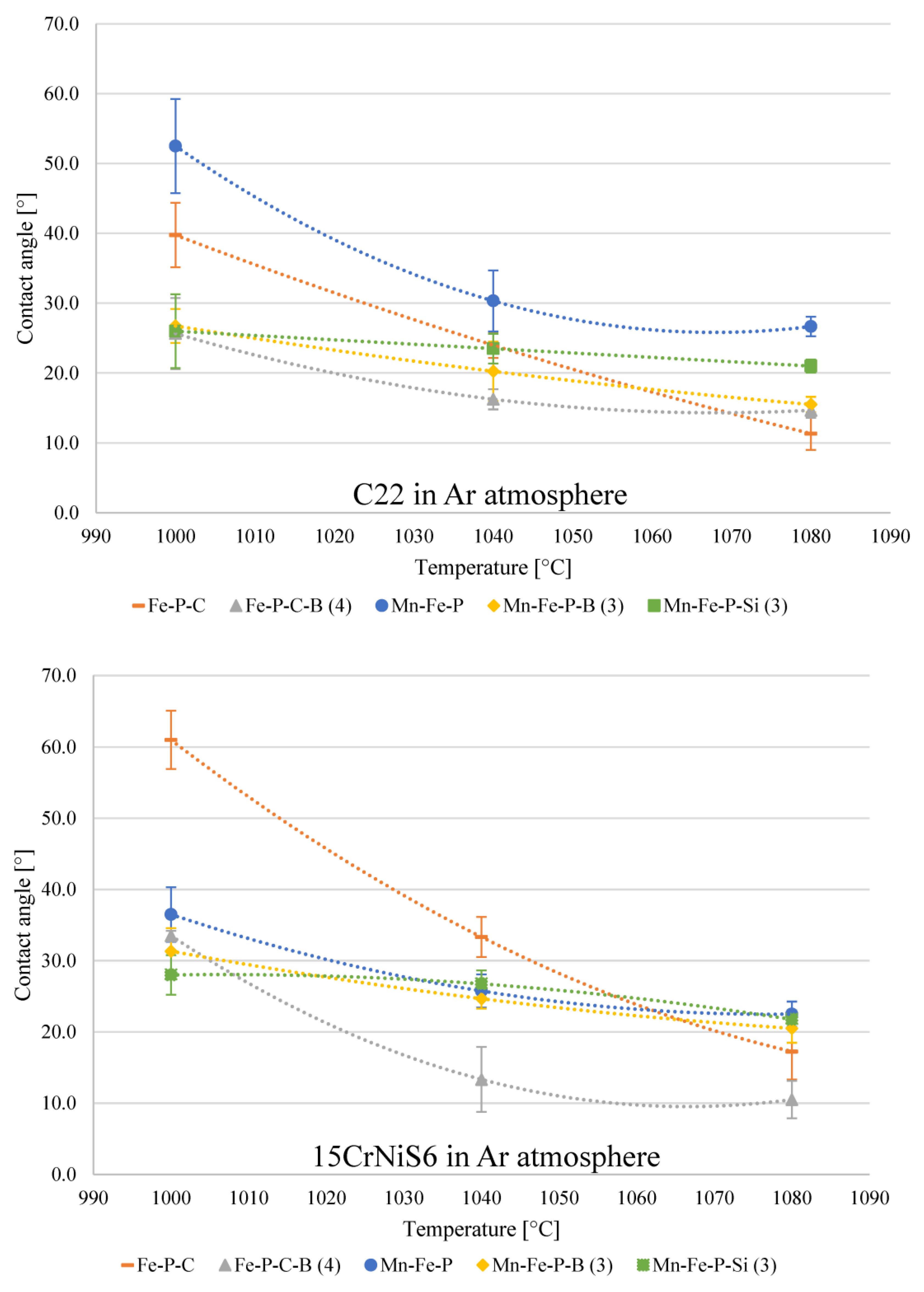
The effect of brazing temperature on the contact angles of selected alloys brazed onto the C22 non-alloy steel and 15CrNiS low-alloy steel at T = 1000 °C, 1040 °C and 1080 °C in an argon atmosphere is shown in Figure 5.
As expected, contact angles decrease with higher brazing temperatures. In some alloys, this effect is much more pronounced than in others. The largest difference between the contact angles at 1000 °C and 1080 °C is observed in Fe–P–C and Mn–Fe–P alloys on C22 steel and Fe–P–C and Fe–P–C–B (4) alloys on 15CrNiS6 steel. The reason lies in a characteristic decrease in surface tension and thus a better flow of the melt as well as a higher reactivity of the molten filler metal towards the base material at higher temperatures. At 1000 °C, the filler metals generally show better wettability on C22 steel. At higher temperatures, the difference between the two steels practically disappears. The reason for this could be a stable chromium oxide surface layer. It seems that the presence of the chemical elements boron, silicon, and manganese, which have lower free energies of the formation of their oxides than chromium, partly contributes to the reduction of chromium oxide in an inert atmosphere and has a positive effect on the wettability at lower temperatures. Phosphorus, on the other hand, has a higher free energy of the oxide formation than chromium [1,43,51]. Fe–P–C alloy that does not contain any of the previously mentioned elements exhibits significantly worse wettability at 1000 °C than other alloys. At higher temperatures, the effects of lower surface tension and higher reactivity of the melt outweigh the effects of boron, silicon, and manganese on the reduction of the chromium oxide. This leads to better flow of the molten filler metal, despite the presence of the aforementioned oxide layer.
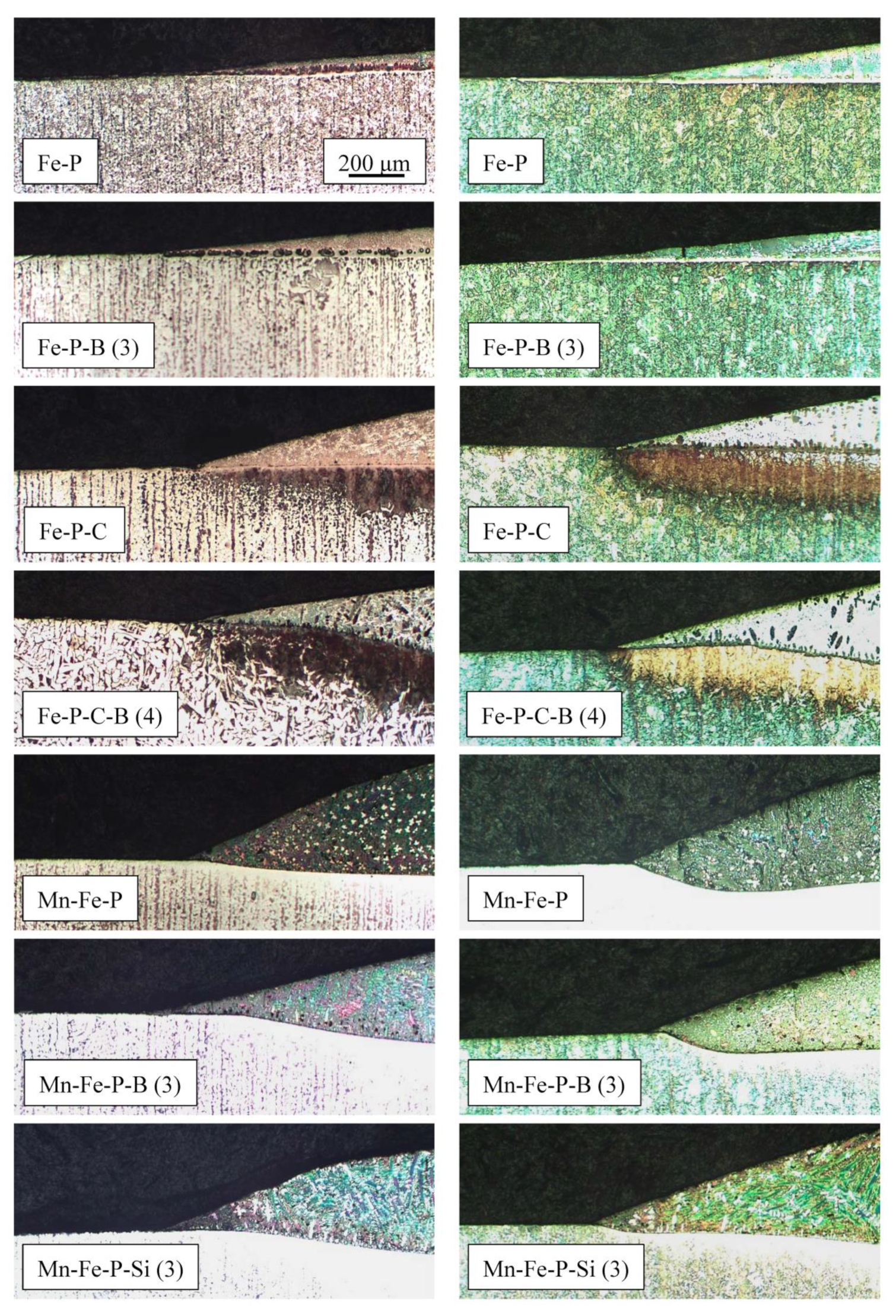
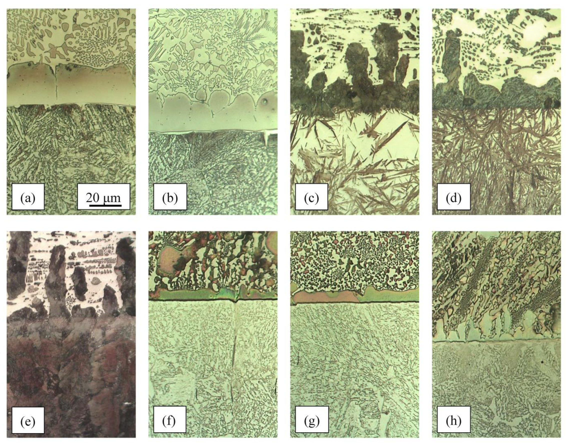
It can be concluded that the brazing temperature T = 1080 °C is appropriate for most of the produced alloys. All alloys are reactive to both the non-alloy and low-alloy steels. The reaction with steel occurs by a more or less pronounced dissolution of the steel surface (Figure 6) and a simultaneous diffusion of alloying elements from the molten filler metals into the solid steel. In the case of carbon, the diffusion can be clearly seen with a brief look under the light microscope. This reveals the carburisation of the steel under the drops at the joint interface (Figure 6).
Admixing of the base material into the brazing filler metals, caused by the dissolution of the steel and a permanent diffusion of the elements P, B, C, and Si into the solid steel, leads to a dealloying of the melt. Despite the hypereutectic composition of most alloys, this dealloying causes the composition of the melt at the joint interface to change to the eutectic composition. This means that there are no primary intermetallic phases in the microstructure in this area. At the same time, a more or less continuous thin layer of solid solution forms at the joint interface. The crystal grains grow from the joint interface into the filler metal (Figure 7). A high carbon content in Fe–P–C and Fe–P–C–B alloys causes the solid solution to form as pearlite, as a consequence of a transformation of austenite. The thickness of the solid solution layer is a few times less in Mn–Fe–P–X alloys than in Fe–P–X alloys. This hints at the much lower rate of diffusion of chemical elements from the melt of Mn–Fe–P–X alloys into the solid steel.
In the case of filler metals with a high carbon content, a strong carburisation of the steel below the joint interface can be observed. This occurs due to the diffusion of carbon from the filler metal into the steel. It causes the formation of a high-carbon martensite layer in the low-alloy, quenched and tempered 15CrNiS6 steel (Figure 6—yellow-brown layer, Figure 7c,d), and a pearlite layer in the non-alloy ferrite–pearlite steel C22 (Figure 6—black and dark brown layer, Figure 7e). The formation of martensite in the carburised layer of the low-alloy steel indicates its improved hardenability.

4. Conclusions

Seventeen experimental, low-cost brazing alloys were developed from eight alloy systems based on Fe–P and Mn–Fe–P with additions of B, C, and Si for brazing of non-alloy and low-alloy steels. The aim of this research was to produce alloys with liquidus temperatures below TL ≈ 1100 °C, as narrow as possible melting ranges, and as low as possible solidus temperatures TS.
Eleven of the produced alloys already fulfil the criteria in a rapidly cooled, as-cast state. Thirteen alloys fulfil the criteria in a homogenised state. A melting range of ΔT ≤ 100 °C is achieved by nine alloys in the as-cast state and by ten alloys in the homogenised state. TS and TL temperatures as well as their melting ranges are comparable to the already known both commercially available and experimental Ni-based and Fe-based brazing filler metals.
Eutectic and primary intermetallic compounds in the microstructure are the reason for the very high hardness and brittleness in the as-cast state, with average hardness ranging from 568 HV10 to 875 HV10. Since similar hard intermetallic compounds are also characteristic of commercially available Ni-based and Fe-based stainless steel brazing filler metals, good wettability and good bonding with low-alloy and non-alloy steels are much more important factors for brazing than hardness.
All alloys show good wettability on non-alloy and low-alloy steel with a chromium content of less than 1.7 wt% at T = 1080 °C and t = 5 min in Ar 4.6 and 78 vol% H2–22 vol% N2 protective atmospheres. The wettability improves with increasing temperature. Nitrogen from the atmosphere can react with the boron in the filler metal and hinder or even prevent the flow of the molten filler metal over the steel surface. It appears that this phenomenon intensifies with the widening of the melting range.
All alloys show good reactive bonding with non-alloy and low-alloy steels. The reaction occurs by a more or less strong dissolution of the steel surface and a simultaneous diffusion of P, B, C, and Si from the molten filler metal into the solid steel. This leads to dealloying of the filler metal. As a results, a solid solution in the form of a more or less continuous layer forms in the joint area between the filler metal and the base metal, as well as in the form of dendrites in the filler metals themselves. The dealloying also causes the composition of the melt to change to a eutectic composition in the area around the joint interface. Despite the hypereutectic composition of most of the filler metals, no primary intermetallic phases can be found in this region. Their initial hypereutectic compositions and high hardness values are therefore of little importance.
In the case of filler metals with a high carbon content, strong carburisation of the steel can be observed below the joint, leading to the formation of a pearlite layer in the non-alloy steel and a high-carbon martensite layer in low-alloy steel.
This study has met expectations. Two basic properties that all good brazing filler metals should possess were demonstrated in the produced experimental low-cost Fe–P-based and Mn–Fe–P-based brazing filler metals with different contents and combinations of B, C, and Si: good wettability and good bonding with the base material. This means that the next logical step is to produce and thoroughly analyse brazed joints on non-alloy and low-alloy steels.

Author Contributions

Conceptualisation, M.Z. and B.Z.; methodology, B.Z.; validation, M.Z., B.Z. and A.N.; formal analysis, B.Z.; investigation, M.Z., B.Z. and J.M.; resources, A.N.; data curation, A.N. and J.M.; writing—original draft preparation, M.Z.; writing—review and editing, B.Z.; visualisation, M.Z., B.Z. and A.N.; supervision, A.N. and B.Z.; project administration, A.N.; funding acquisition, M.Z. and A.N. All authors have read and agreed to the published version of the manuscript.

Funding

Funding was provided by ARRS (Javna agencija za raziskovalno dejavnost Republike Slovenije); Grants P2-0205 and P1-0195.

Data Availability Statement

Data are available upon request.

Acknowledgments

We thank Metallography at the Faculty of Natural Sciences and Engineering, University of Ljubljana for allowing us to perform a part of the experiments on their equipment. A special thanks is given to EXOTERM-IT d.o.o., Struževo 66, 4000 Kranj, for their donation of raw materials used in the production of the brazing filler metals. A special thanks is given to ETA Cerkno d.o.o., Goriška cesta 19, 5282 Cerkno, for allowing us to carry out the brazing of the samples on their production line.

Conflicts of Interest

The authors declare no conflict of interest. The funders had no role in the design of the study; in the collection, analyses, or interpretation of data; in the writing of the manuscript; or in the decision to publish the results.

References

  1. Sheward, G. High Temperature Brazing in Controlled Atmospheres; Pergamon Press: Oxford, UK, 1985. [Google Scholar]
  2. Cole, N.C.; Gunkel, R.W. Development of Corrosion Resistant Filler Metals for Brazing Molybdenum. Weld. J. 1973, 10, 466-s–473-s. [Google Scholar]
  3. Pattanaik, S. Iron-Nickel Base Brazing Filler Metal. U.S. Patent 4,402,742, 6 September 1983. [Google Scholar]
  4. Pohlman, M.J.; Kindlimann, L.E. Iron-Based Brazing Alloy Compositions and Brazed Assemblies with Iron Based Brazing Alloys. U.S. Patent 4,410,604, 18 October 1983. [Google Scholar]
  5. Coad, B.C. Method of Brazing with Iron-Based and Hard Surfacing Alloys. U.S. Patent 4,516,716, 14 May 1985. [Google Scholar]
  6. Khan, T.I.; Wallach, E.R. Transient Liquid Phase Bonding of Oxide Dispersion Strengthened Ferritic Superalloys. Int. Trend Weld. Sci. Technol. 1993, 1095–1099. [Google Scholar]
  7. Nakao, Y.; Shinozaki, K. Transient liquid phase diffusion bonding of Fe-base oxide dispersion strengthened alloy MA956. Mater. Sci. Technol. 1995, 11, 304–311. [Google Scholar] [CrossRef]
  8. Müller, W.; Müller, J.W. Löttechnik; DVS Media GmbH: Düsseldorf, Germany, 1995. [Google Scholar]
  9. Kvasnitskyy, V.F.; Samokhin, S.M.; Galiatkin, S.N. Das Löten von nichtrostenden Stählen mit Molybdën. In Hart- und Hochtemperaturlöten und Diffusionsschweißen = Brazing, High Temperature Brazing and Diffusion Welding; DVS Media GmbH: Düsseldorf, Germany, 1998; pp. 269–270. [Google Scholar]
  10. Xia, C.; Li, Y.; Gong, Y.; Wu, L.; Liu, P.; Li, Y. Microstructure and Fracture of 50Mo-50Re Vacuum Brazed with Fe-Si-B Filler Metal. Mater. Res. 2019, 22, e20180730. [Google Scholar] [CrossRef]
  11. Wang, J.; Lian, Y.; Feng, F.; Liu, X.; Chen, Z.; Wang, Y.; Qiang, J.; Wei, M. Tungsten/reduced activation ferritic–martensitic steel joints made with an Fe–Si–B amorphous filler. Mater. Sci. Technol. 2021, 37, 1199–1206. [Google Scholar] [CrossRef]
  12. Rabinkin, A.; Decristofaro, N.J. Iron-Based Brazing Filler Metals. U.S. Patent 0,090,820 A1, 4 May 2006. [Google Scholar]
  13. Rabinkin, A.; Decristofaro, N.J. Iron-Chromium Base Brazing Filler Metals. U.S. Patent 6,656,292B1, 3 December 2003. [Google Scholar]
  14. Rangaswamy, S.; Fortuna, D.J. Iron-Based Braze Filler Metal for High-Temperature Applications. U.S. Patent 7,392,930B2, 1 July 2008. [Google Scholar]
  15. Verduzco, J.A.; Gonzalez-Sanchez, J.; Verduzco, V.H.; Solis, J.; Lemus-Ruiz, J. Microstructure and electro-chemical properties of the bonding zone of AISI 316L steel joined with a Fe-based amorphous foil. J. Mater. Process. Technol. 2010, 210, 1051–1060. [Google Scholar] [CrossRef]
  16. Jabbari, F.; Ekrami, A. Conventional vs. Temperature-Gradient Transient Liquid Phase Bonding of Stainless Steel 304 Using a Multi-component (Fe–Ni–Mo–B) Filler Metal. Metall. Mater. Trans. A 2022, 53, 4081–4100. [Google Scholar] [CrossRef]
  17. Wolfe, C.; Eklund, T.; Persson, O. Investigation of the corrosion performance of different braze fillers fused onto stainless steel type 1.4401 (UNS S31600). In Hart- und Hochtemperaturlöten und Diffusionsschweißen = Brazing, High Temperature Brazing and Diffusion Welding; DVS Media GmbH: Düsseldorf, Germany, 2004; pp. 278–280. [Google Scholar]
  18. Lugscheider, E.; Ferrara, S.; Humm, S.; Wielage, B.; Hoyer, I. Entwicklung neuer Lote für das Hochtemperaturlöten mechanisch hoch beanspruchter Stahlkomponenten. Schweißen Schneid. 2005, 57, 25–31. [Google Scholar]
  19. Hoyer, I.M. Beitrag zur Entwicklung von Hochtemperaturloten auf Eisenbasis; Technischen Universität Chemnitz: Chemnitz, Germany, 2005. [Google Scholar]
  20. Larsson, H.; Rassmus, J. Properties of pressure fatigue loaded brazed heat exchangers in stainless steel brazed with Cu-, Ni- or Fe-based fillers. In Hart- und Hochtemperaturlöten und Diffusionsschweißen = Brazing, High Temperature Brazing and Diffusion Welding; DVS Media GmbH: Düsseldorf, Germany, 2007; pp. 135–139. [Google Scholar]
  21. Persson, U. New iron-chromium based brazing filler metal for demanding stainless steel applications. In Proceedings of the 4th International Brazing & Soldering Conference (IBSC), Orlando, FL, USA, 16–29 April 2009. [Google Scholar]
  22. Persson, U. Iron-based brazing filler metals for high temperature brazing of stainless steel. In Hart- und Hochtemperaturlöten und Diffusionsschweißen = Brazing, High Temperature Brazing and Diffusion Bonding; DVS Media GmbH: Düsseldorf, Germany, 2010; pp. 38–41. [Google Scholar]
  23. Matsu, K.; Sawada, T.; Fukumoto, S.; Miyazawa, Y.; Ariga, T. Mechanical properties of Fe-Cr based brazing filler metals. In Hart- und Hochtemperaturlöten und Diffusionsschweißen = Brazing, High Temperature Brazing and Diffusion Bonding; DVS Media GmbH: Düsseldorf, Germany, 2010; pp. 48–51. [Google Scholar]
  24. Wielage, B.; Hoyer, I.; Hausner, S. Development of iron filler metals for high-temperature brazing of materials in contact with drinking water. In Hart- und Hochtemperaturlöten und Diffusionsschweißen = Brazing, High Temperature Brazing and Diffusion Bonding; DVS Media GmbH: Düsseldorf, Germany, 2010; pp. 189–195. [Google Scholar]
  25. Bobzin, K.; Kopp, N.; Puidokas, S.; Tillmann, W.; Wojarski, L.; Manka, M.; Liu, C. Reliable design procedure of iron-based braze joints. In Brazing, High Temperature Brazing and Diffusion Bonding; DVS Media GmbH: Düsseldorf, Germany, 2013; pp. 261–266. [Google Scholar]
  26. Weis, S.; Elßner, M.; Wagner, G. Influence of the microstructure on the properties of Fe-based brazed joints. In Brazing, High Temperature Brazing and Diffusion Bonding; DVS Media GmbH: Düsseldorf, Germany, 2016; pp. 207–211. [Google Scholar]
  27. Battenbough, A.J.; Osmanda, A.M.; Weinstein, M.; Lee, L.; Johnson, L. Properties of selected nickel and iron base brazing filler metals. In Brazing, High Temperature Brazing and Diffusion Bonding; DVS Media GmbH: Düsseldorf, Germany, 2016; pp. 404–410. [Google Scholar]
  28. Uhlig, T.; Fedorov, V.; Weis, S.; Wagner, G. Untersuchung der Gefüge-Eigenschafts-Beziehungen von Eisenbasisloten. Schweiss. Schneid. 2018, 70, 308–314. [Google Scholar]
  29. Ren, H.S.; Xiong, H.P.; Ye, L.; Ren, X.Y.; Li, W.W.; Qin, R.Y. Microstructures and mechanical properties of TiAl/Ni-based superalloy joints brazed with Fe-based filler metal. Weld. World 2020, 65, 79–85. [Google Scholar] [CrossRef]
  30. Li, H.; Zhang, X.; Mårs, O.; Zhao, X.; Lu, Q.; Chen, Z. The effect of iron-based filler metal element on the properties of brazed stainless steel joints for EGR cooler applications. Weld. World 2018, 63, 263–275. [Google Scholar] [CrossRef]
  31. Lugscheider, E.; Schlimbach, K. Qualifizieren der Löttechnologie für das Fügen von Intermetallischen Phasen. In Hart- und Hochtemperaturlöten und Diffusionsschweißen = Brazing, High Temperature Brazing and Diffusion Welding; DVS Media GmbH: Düsseldorf, Germany, 2001; pp. 50–54. [Google Scholar]
  32. Lee, D.; Welsch, G.E. Low-Melting Iron-Based Filler Alloys. U.S. Patent 2015/0,158,127A1, 11 July 2015. [Google Scholar]
  33. Bolkcom, W.T.; Knapp, W.E. Manganese-Nickel base Brazing Alloys. U.S. Patent 2,872,309, 3 February 1959. [Google Scholar]
  34. Cape, A.T. Manganese-Base Brazing Alloys. U.S. Patent 3,124,451, 10 March 1964. [Google Scholar]
  35. Shi, H.; Yan, J.; Li, N.; Zhu, X.; Chen, K.; Yu, L. Microstructure and properties of FeCrMo damping alloys brazing joint using Mn-based brazing filler. Vacuum 2019, 159, 209–217. [Google Scholar] [CrossRef]
  36. Yuan, L.; Ren, J.; Xiong, J.; Zhao, W.; Shi, J.; Li, J. Transient liquid phase bonding of Ni3Al based superalloy using Mn-Ni-Cr filler. J. Mater. Res. Technol. 2021, 11, 1583–1593. [Google Scholar] [CrossRef]
  37. Chen, L.; Chen, H.; Yang, W.; Zhang, Q.; Yang, B.; Hu, Y.; Si, X.; Lin, T.; Cao, J.; Qi, J.; et al. Interfacial Microstructure and Mechanical Properties of 1Cr18Ni9Ti/1Cr21Ni5Ti Stainless Steel Joints Brazed with Mn-Based Brazing Filler. Materials 2022, 15, 7021. [Google Scholar] [CrossRef] [PubMed]
  38. Zhang, C.; Chen, H.; Yang, W.; Zhang, Q.; Yang, B.; Hu, Y.; Li, C.; Gao, D.; Si, X.; Qi, J.; et al. Effect of the Surface States of 1Cr18Ni9Ti Stainless Steel on Mn-Based Brazing Alloy Wetting. Coatings 2022, 12, 1328. [Google Scholar] [CrossRef]
  39. Mu, R.; Wang, Y.; Niu, S.; Sun, K.; Yang, Z. Wetting of FeCoCrNiTi0.2 high entropy alloy on the (HfZrTiTaNb)C high entropy ceramic. J. Eur. Ceram. Soc. 2023. [Google Scholar] [CrossRef]
  40. Zhang, Z.; Zhang, J.; Zhang, M.; Peng, P. First-principles calculations on brazed diamond with FeCoCrNi high entropy alloys doped with strong carbide-forming elements. Solid State Commun. 2022, 357, 114980. [Google Scholar] [CrossRef]
  41. Kovalenko, E.; Krasanov, I.; Valdaytseva, E.; Klimova-Korsmik, O.; Gushchina, M. Influence of Laser Direct Energy Deposition Process Parameters on the Structure and Phase Composition of a High-Entropy Alloy FeCoNiCrMn. Metals 2023, 13, 534. [Google Scholar] [CrossRef]
  42. Liu, J.; Lin, D.; Hu, J.; Xi, X.; Tang, Z.; Liu, Z.; Hu, S.; Bian, H.; Song, X. Microstructure and mechanical properties of a GH3536/SS304 joint brazed with a Co25Fe25Mn5Ni25Ti20 eutectic high-entropy alloy filler. Mater. Charact. 2022, 193, 112305. [Google Scholar] [CrossRef]
  43. Jacobson, D.M.; Humpston, G. Principles of Brazing; ASM International: Materials Park, OH, USA, 2005. [Google Scholar]
  44. Guzman-Flores, I.; Vargas-Arista, B.; Garcia-Vázquez, F.; Granda-Gutiérrez, E.; Gómez- Jiménez, R.; Rabindrantah-Galván-Gil, J. Wide-gap joints in inconel 738 super alloy by vacuum brazing: Microstructure and microhardness. Dyna Ing. E Ind. 2018, 94, 318–323. [Google Scholar] [CrossRef]
  45. Brazing Handbook, 4th ed.; American Welding Society: Miami, FL, USA, 1991.
  46. Standard EN ISO 6507-1:2018; Metallic materials – Vickers hardness test – Part 1: Test method. CEN: Brussels, Belgium, 2018.
  47. Gundlach, R.B.; Doane, D.V. Alloy Cast Irons. In ASM Handbook; Properties and Selection: Irons, Steels, and High Performance Alloys; ASM International: Materials Park, OH, USA, 2008; Volume 1, pp. 85–104. [Google Scholar]
  48. Roberts, G.; Krauss, G.; Kennedy, R. Tool Steels, 5th ed.; ASM International: Materials Park, OH, USA, 1998; pp. 59, 83–85. [Google Scholar]
  49. Zorc, M.; Nagode, A.; Burja, J.; Kosec, B.; Bizjak, M.; Zorc, B. Preliminary Study of New Low-Temperature Hard Abrasion Resistant Fe-P and Fe-P-X (X = C or/and B) Casting Alloys. Materials 2023, 16, 3766. [Google Scholar] [CrossRef]
  50. Standard ISO 17672:2016; Brazing–Filler Metals. ISO: Geneva, Switzerland, 2016.
  51. Probst, R.; Herold, H. Kompendium der Schweiβtechnik, Band 2: Schweiβmetallurgie; DVS-Verlag GmbH: Düsseldorf, Germany, 1997. [Google Scholar]
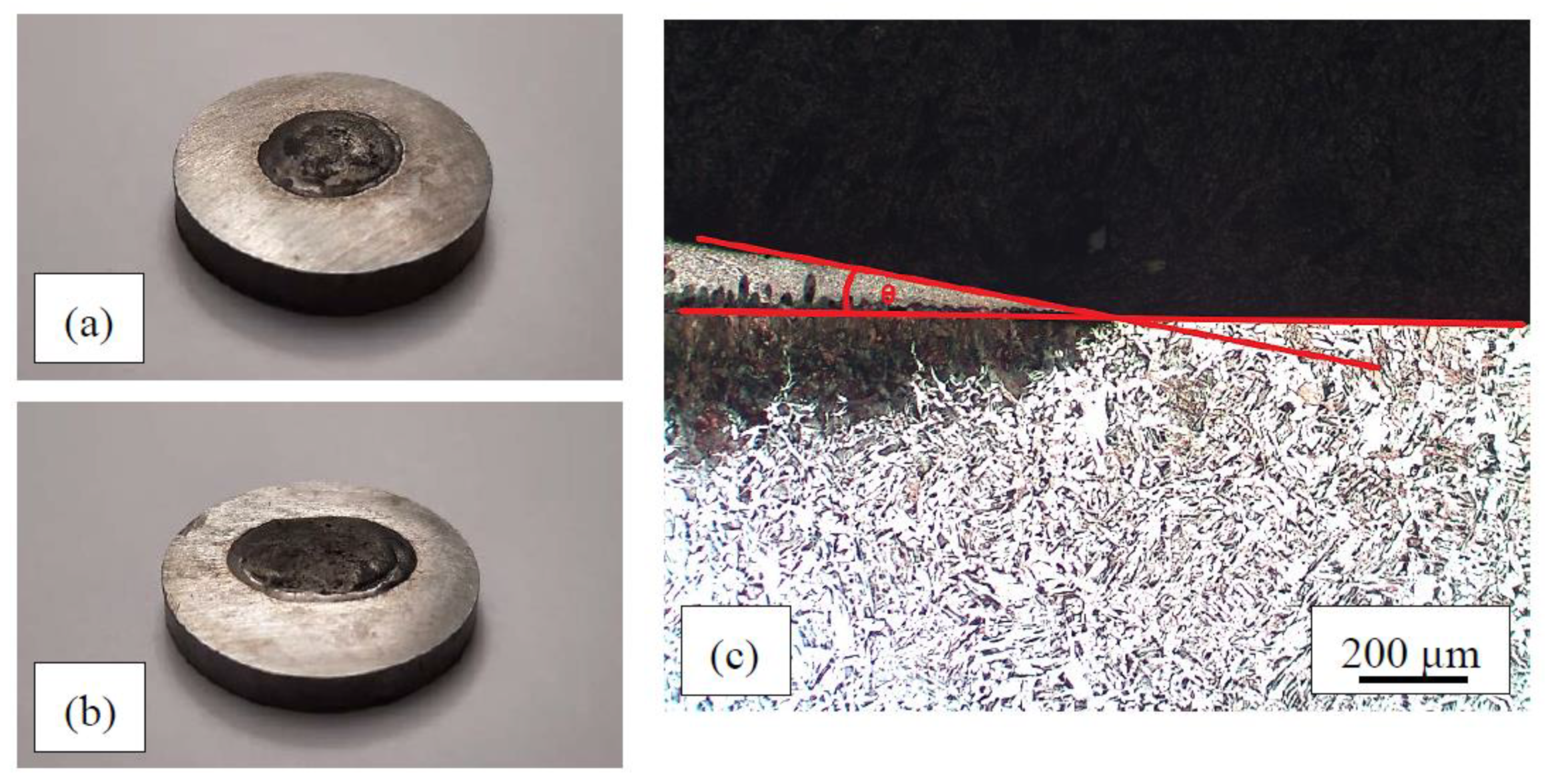
Figure 1. Examples of filler metal drops on the steel: (a) Mn–Fe–P–B (1) alloy; (b) Mn–Fe–P–C alloy; (c) sessile drop method used to measure contact angles.
Metals 13 01513 g001
Figure 2. DSC curves data from [49] and microstructures of Fe–P–B (1) alloy: (a) heating curve, ∆H = −60.8 J/g; (b) cooling curve, ∆H = 105.4 J/g.
Metals 13 01513 g002
Figure 3. DSC curves and microstructures of Mn–Fe–P–B (3) alloy: (a) heating curve, ∆H = −85.98 J/g; (b) cooling curve, ∆H = 94.86 J/g.
Metals 13 01513 g003
Figure 4. DSC heating curves and microstructures of alloys in rapidly cooled, as-cast state; (a) Fe–P (DSC analysis of Fe–P alloy was not performed; note under Table 1); (b) Fe–P–B (3), ΔH = −80.89 J/g data from [49]; (c) Fe–P–C, ΔH = −105.6 J/g data from [49]; (d) Fe–P–C–B (4), ΔH = −71.44 J/g data from [49]; (e) Mn–Fe–P, ΔH = −74.44 J/g; (f) Mn–Fe–P–Si (3), ΔH = −40.07 J/g.
Metals 13 01513 g004aMetals 13 01513 g004b
Figure 5. The effect of temperature on wettability of chosen alloys on C22 and 15CrNiS6 steels in Ar 4.6 atmosphere.
Metals 13 01513 g005
Figure 6. Sections of the drops of selected filler metals on the steel surface; left column: C22 steel; right column: 15CrNiS6 steel; T = 1080 °C, t = 5 min, Ar 4.6; all pictures taken at same magnification.
Metals 13 01513 g006
Figure 7. The microstructure at the joint interface: (a) Fe–P; (b) Fe–P–B (3); (c) Fe–P–C; (d) and (e) Fe–P–C–B (4); (f) Mn–Fe–P; (g) Mn–Fe–P-B (3); (h) Mn–Fe–P-Si (3); all on 15CrNiS6 steel except (e) on C22 steel; T = 1080 °C, t = 5 min, Ar 4.6; the layer of solid solution is between the steel (lower part of the pictures) and the filler metal (upper part of the pictures); all pictures taken at same magnification.
Metals 13 01513 g007
Table 1. Chemical compositions [wt%] and melting ranges [°C] of experimental brazing filler alloys.
Filler Metals #FeMnPBCSi≈ TS-L
Heating
T
Heating
≈ TS-L
Cooling
T
Cooling
Fe–Prest0.769.9/0.110.191050–1070 *201050–1070 *20
Fe–P–B (1)rest0.777.02.10.080.211001–1180179932–1091159
Fe–P–B (2)rest1.409.32.50.100.211053–12201671041–1196155
Fe–P–B (3)rest0.577.60.730.070.081000–105656979–103960
Fe–P–Crest1.577.4/2.200.34954–99036918–94325
Fe–P–C–B (1)rest1.007.21.31.620.16954–1082128915–100792
Fe–P–C–B (2)rest3.806.82.11.500.53956–1189233925–1150225
Fe–P–C–B (3)rest1.307.12.61.210.23956–1212256930–1185255
Fe–P–C–B (4)rest1.907.50.740.620.50956–104084916–99175
Mn–Fe–P34.2956.197.9/0.710.55924–97147886–94357
Mn–Fe–P–B (1)38.6049.608.31.40.470.57928–1131203894–1089195
Mn–Fe–P–B (2)43.6943.007.82.40.491.06940–1223283890–1157267
Mn–Fe–P–B (3)35.3055.886.90.810.760.35934–103298889–98798
Mn–Fe–P–Si (1)33.4047.037.8/0.568.501001–105857972–101240
Mn–Fe–P–Si (2)32.8846.557.7/0.479.401026–109064976–102549
Mn–Fe–P–Si (3)34.1052.498.3/1.993.10943–100057897–95760
Mn–Fe–P–C31.7157.917.5/2.620.26918–1040122881–999118
# Filler metals may include Al, Cr, Ni, Cu, V, and Ti as well in quantities of up to 0.5 wt% per individual element; * From the Fe–P phase diagram taking into account the chemical compositions, as the DSC could not analyze this alloy due to its too high P content (quote from the equipment operator); melting range was measured in a furnace in Ar atmosphere by heating it up to T = 1180 °C.
Table 2. HV10 hardness of bulk experimental brazing filler alloys.
AlloyMin.Max.SDsHMean HV/≈ HRC∆HV
Fe–P56560613.8589/52.541
Fe–P–B (1)67878940.2718/59111
Fe–P–B (2)71082439.6771/61.5114
Fe–P–B (3)56260816.4588/52.546
Fe–P–C62077453.3715/59154
Fe–P–C–B (1)74094374.2875/65203
Fe–P–C–B (2)67986875.5787/62189
Fe–P–C–B (3)74285741.5805/62.5115
Fe–P–C–B (4)63175642.6700/58125
Mn–Fe–P56662119.5599/5355
Mn–Fe–P–B (1)70277524.2746/6073
Mn–Fe–P–B (2)69079237.4749/60102
Mn–Fe–P–B (3)54859213.3568/51.544
Mn–Fe–P–Si (1)63783461.0726/59.5197
Mn–Fe–P–Si (2)67379644.7752/60123
Mn–Fe–P–Si (3)51276699.5660/56.5254
Mn–Fe–P–C81485815.7833/6344
Table 3. Wettability of experimental alloys on C22 steel at T = 1080 °C.
AlloyH2–N2 Mixture—Contact Angles θ [°]Ar 4.6—Contact Angles θ [°]
Min.Max.SDMeanMin.Max.SDMean
Fe–P371.25.2340.53.5
Fe–P–B (1)10162.012.8381.85.8
Fe–P–B (2)11172.114.4392.26.0
Fe–P–B (3)9100.59.4282.34.5
Fe–P–C8173.112.59141.811.3
Fe–P–C–B (1)6111.87.811130.712.0
Fe–P–C–B (2)did not melt9110.89.8
Fe–P–C–B (3)did not melt5102.18.5
Fe–P–C–B (4)6142.510.014160.814.8
Mn–Fe–P8121.410.525281.126.8
Mn–Fe–P–B (1)23313.127.26122.39.8
Mn–Fe–P–B (2)23354.328.87142.911.8
Mn–Fe–P–B (3)20303.123.514171.115.5
Mn–Fe–P–Si (1)23312.627.823250.724.0
Mn–Fe–P–Si (2)37452.641.224302.326.3
Mn–Fe–P–Si (3)15212.217.720220.721.0
Mn–Fe–P–C11224.016.221261.924.0
Table 4. Wettability of chosen alloys on 15CrNiS6 steel at T = 1080 °C.
AlloyH2–N2 Mixture—Contact Angles θ [°]Ar 4.6—Contact Angles θ [°]
Min.Max.SDMeanMin.Max.SDMean
Fe–P8100.79.07111.58.8
Fe–P–B (3)7121.99.8271.84.5
Fe–P–C780.57.513192.315.3
Fe–P–C–B (4)10193.614.57142.710.5
Mn-Fe–P10182.913.320251.822.5
Mn–Fe–P-B (3)17232.120.018232.120.5
Mn–Fe–P-Si (3)19283.223.520231.321.8
Disclaimer/Publisher’s Note: The statements, opinions and data contained in all publications are solely those of the individual author(s) and contributor(s) and not of MDPI and/or the editor(s). MDPI and/or the editor(s) disclaim responsibility for any injury to people or property resulting from any ideas, methods, instructions or products referred to in the content.