Article

Controlling the Amount of Copper Formate Shells Surrounding Cu Flakes via Wet Method and Thermo-Compression Sinter Bonding between Cu Finishes in Air Using Flakes

Department of Materials Science and Engineering, Seoul National University of Science and Technology, Seoul 139-743, Republic of Korea
*
Author to whom correspondence should be addressed.
Metals 2023, 13(9), 1516; https://doi.org/10.3390/met13091516
Submission received: 26 July 2023 / Revised: 21 August 2023 / Accepted: 24 August 2023 / Published: 25 August 2023
(This article belongs to the Special Issue Novel Technologies for Metal Microjoining)

Abstract

:
To bond a semiconductor power chip on a substrate using the formation of bondlines exhibiting long-term mechanical durability at high temperatures such as 300 °C, compression-assisted sinter bonding between Cu finishes was carried out at 300–350 °C in air. Cu flakes of approximately 7 µm were used as the main filler material; their surfaces were modified by pretreatment using a formic acid solution, and the existing oxide layers were transformed into copper formate shells. To increase the amount of the copper formate shells, the shell transformation reaction was controlled by the deliberate addition of 30 nm Cu2O particles and sustained for 50 min. The formate shells formed decomposed at a peak temperature of 250 °C, forming pure Cu, which rapidly induced sintering between the flakes and at the Cu-finish–flake interfaces. Therefore, the paste containing Cu flakes showed a sufficient shear strength of 26.3 MPa even in air after sinter bonding for only 3 min under 5 MPa at 350 °C. Although the bimodal-type paste presented near-full-density bondline structures within 3 min of adding 350 nm pure Cu particles, the strengths with respect to bonding time showed trends of values less than 26.3 MPa, owing to the excessive oxidation of the 350 nm Cu.

Graphical Abstract

1. Introduction

For the attachment and stable connection of wide band-gap semiconductor power devices used at high operating temperatures of 200–300 °C [1], or other high heat-generating devices [2], the current solder joints should be replaced with either Ag [3] or Cu [4] bondlines. This is because they no longer provide long-term mechanical durability owing to their lower melting points [5,6]. Hence, a bonding process involving the sintering of Ag or Cu particles is considered a next-generation bonding technique that can provide superior mechanical reliability even at high temperatures [7,8] and high thermal conductivities [9].
Bonding using Ag or Cu particles should be performed through solid-state sintering [10], considering the reported bonding temperature range of 250–350 °C [11,12]. Even if the high surface energy in the particle state enables sintering at temperatures significantly lower than the melting point, the resultant bondline provides a high melting point identical to that of the bulk [13,14]. Furthermore, the thermal conductivity in the bondline is higher than that in solder joints [15], although the value can vary significantly based on the void fraction in the bondline [16]. However, a long bonding time is inevitably required for sinter bonding [17]; therefore, reducing the bonding time through the compression-assisted method is a crucial research topic for increasing productivity [18,19,20,21].
Recent research has focused on sinter bonding between Cu finishes using Cu particles owing to the low cost of bonding material and the elimination of an additional Ag coating process for the current Ag finish. However, Cu is susceptible to oxidation in air, and its degree of oxidation increases with increasing temperature [22,23,24]. The oxidized layer on the Cu surface forms a rough contour [25] or detached shell structure [26], making sintering between Cu particles difficult by diminishing the physical contact between them. Hence, removing the existing oxide layers on the particles and suppressing oxidation during heating for bonding are fundamental factors in successfully performing sinter bonding using a paste containing Cu particles. Most studies on sinter bonding using Cu paste have adopted reductive formulations to remove oxide layers and particular atmospheres, such as reducing atmospheres with formic acid vapor [27] or inert atmospheres [28,29,30]. However, the formation of a copper compound surface layer by a direct surface modification of Cu particles may be more effective than indirect methods, such as reductive formulation and atmosphere control, owing to the elimination of the initial Cu oxide layers and suppression of Cu oxidation as a barrier during bonding at high temperatures in air. Moreover, the copper compound layer can generate pure Cu atoms in situ, which is favorable for sinter bonding, together with the removal of the barrier by decomposition at a specific temperature. As a representative example, Kim et al. fabricated copper formate layers on Cu nanoparticles with an average size of 100 nm and subsequently prepared a conductive ink as a mixture of the particles and 1-methoxy-2-propanol [31]. With the benefits of the copper formate layers, a film formed after sintering the ink for 1 h at 250 °C in nitrogen and had a low electrical resistivity of 13.5 µΩ∙cm [31]. However, research on making a paste with Cu particles that have formed copper formate layers on the surfaces and performing sinter bonding using the paste has not been well reported. Due to the fact that, unlike the filler in ink, the filler size in paste reaches several to tens of micrometers, the thickness of the copper formate layer should be thickened in proportion; however, there has been no discussion on how to increase the thickness of the copper formate layer. Therefore, after developing a low-cost process that covers micrometer-sized Cu particles with a sufficient thickness of copper formate layer, it is required to evaluate its sinter bonding characteristics by preparing a paste using the particles as filler.
In this study, a novel thermo-compression sinter bonding technology under air using a paste containing copper formate-coated Cu particles was developed between the upper and lower surface finishes of low-cost Cu. Copper formate layers were formed on Cu particles easily through the wet method, and the optimal formate-coating thickness for sinter bonding was investigated. Although the air atmosphere may be a harsh condition for sinter bonding considering the drastic decrease in sinterability between Cu particles due to oxidation, it would provide a good opportunity to evaluate the usefulness of the combination of a copper formate layer and thermo-compression by analyzing the sinter bonding results obtained without a special reductive formulation. Furthermore, we adopted micron-sized Cu flakes instead of Cu nanoparticles as the filler material, considering the merits of their low cost, absence of aggregation, and ease of application to commercial conductive pastes [32].

2. Materials and Methods

2.1. Surface Treatment of Cu Flakes

Purchased Cu flakes (CFL07, size: 6.5–7.2 µm, average thickness: 1.2 µm, JoinM, Nonsan-city, Republic of Korea) were surface-treated to fabricate a core-shell structure as follows: Cu flakes of 9 g were immersed in ethyl alcohol (95%, Samchun Pure Chemical Co., Ltd., Seoul, Republic of Korea) and ultrasounded for 5 min to form a homogeneous suspension. Next, 5 mL of formic acid (85%, Samchun Pure Chemical) was added to the Cu flake suspension and stirred at 250 rpm for 10 min at room temperature (RT) to form copper formate seed layers on the surfaces. Subsequently, Cu2O (size: 20–30 nm, CNVISION Co., Ltd., Seoul, Republic of Korea), a precursor for copper formate, was added to the suspension, and the mixed solution was stirred at 250 rpm for 10 to 50 min to develop the copper formate shells. After the surface treatment, the Cu flakes were washed three times with ethyl alcohol and dried at RT in a vacuum chamber. Schematic illustrations regarding the surface treatment procedure of Cu flakes are shown in Figure 1a.

2.2. Paste Preparation

Pastes containing Cu flakes surface-treated with formic acid were prepared by mixing with an α-terpineol (purity: 98.5%, Samchun Pure Chemical) at a particle-to-vehicle weight ratio of 82:18. The premixture was then homogeneously mixed using a spatula to obtain a stable viscosity for subsequent printing and was called single-modal paste (SM paste). To prepare the other paste, 350 nm sized pure Cu particles, synthesized in the laboratory using the wet method, were mixed with the flakes at a weight ratio of 6:4 to enhance the sinterability between the particles by increasing the packing factor. This paste was named bimodal paste (BM paste).

2.3. Sinter Bonding

Both chips and substrates for sinter bonding were prepared as dummies with Cu plates with dimensions of 3 × 3 × 1 mm3 and 10 × 10 × 1 mm3, respectively. The Cu plates were polished with 2000-mesh sandpaper and then immersed in a 10% H2SO4 water solution for 1 min to remove surface oxides. The prepared pastes were stencil printed onto the surface of a Cu dummy substrate using a stencil mask with a slit of 3 × 3 × 0.1 mm3. Subsequently, the printed pattern was dried at 150 °C for 30 s to remove terpineol by vaporization, followed by placing the dummy chip in alignment. Next, sinter bonding in air was performed at 300 °C or 350 °C by thermo-compression bonding under 5 MPa. Compression was applied throughout the process. The degree of bonding in the bondline was analyzed as a function of bonding time. Schematic illustrations regarding the sinter bonding procedure are provided in Figure 1b.

2.4. Characterization

High-resolution scanning electron microscopy (HR-SEM, SU8010, Hitachi High-Technologies Corp., Tokyo, Japan) was used to examine the particle morphology and bondline microstructure. To closely observe the surface-treated particles, cross-sectional samples were prepared using a focused ion beam (FIB, Helios 650, FEI, Hillsboro, OR, USA) and examined using transmission electron microscopy (TEM, JEM-2010, JEOL Ltd., Tokyo, Japan). In addition, the thermodynamic behavior of the surface-treated particles was analyzed using thermogravimetry-differential thermal analysis (TG-DTA, DTG-60H, Shimadzu Corp., Kyoto, Japan) by heating in air from 25 to 400 °C at a heating rate of 20 °C/min. X-ray diffraction (XRD) (DE/D8 Advance, Bruker Corp., Billerica, MA, USA) and X-ray photoelectron spectroscopy (XPS, K-Alpha+, Thermo Fisher Scientific Inc., Waltham, MA, USA) were used to determine the transitions of the phases and chemical states before and after surface treatment. The mechanical strengths of the bondlines were measured using a shear tester (DAGE-series-4000, Nordson Corp., Westlake, OH, USA) at a shear rate of 200 μm/s. Shear strength was determined as the maximum strength measured during shearing.

3. Results and Discussion

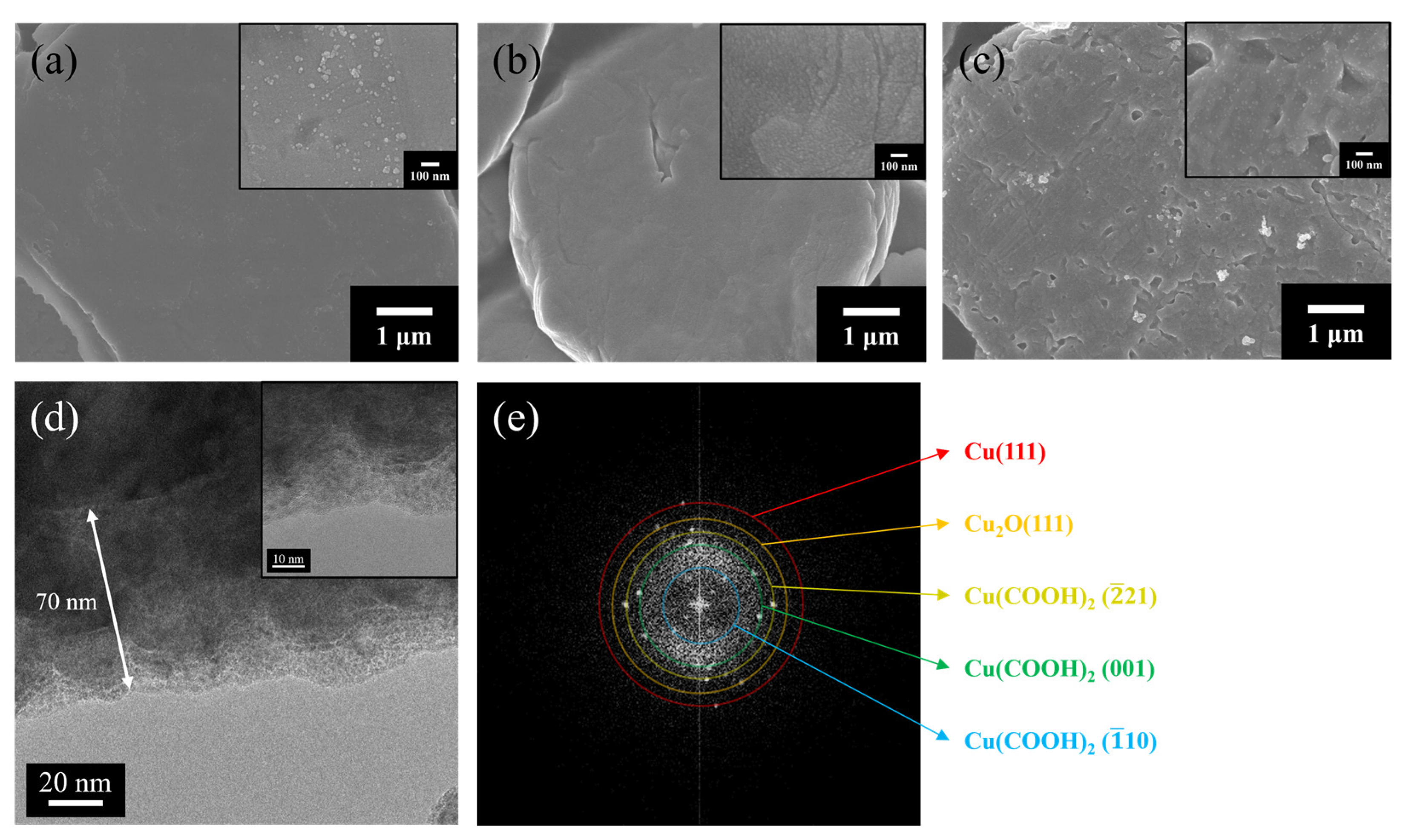
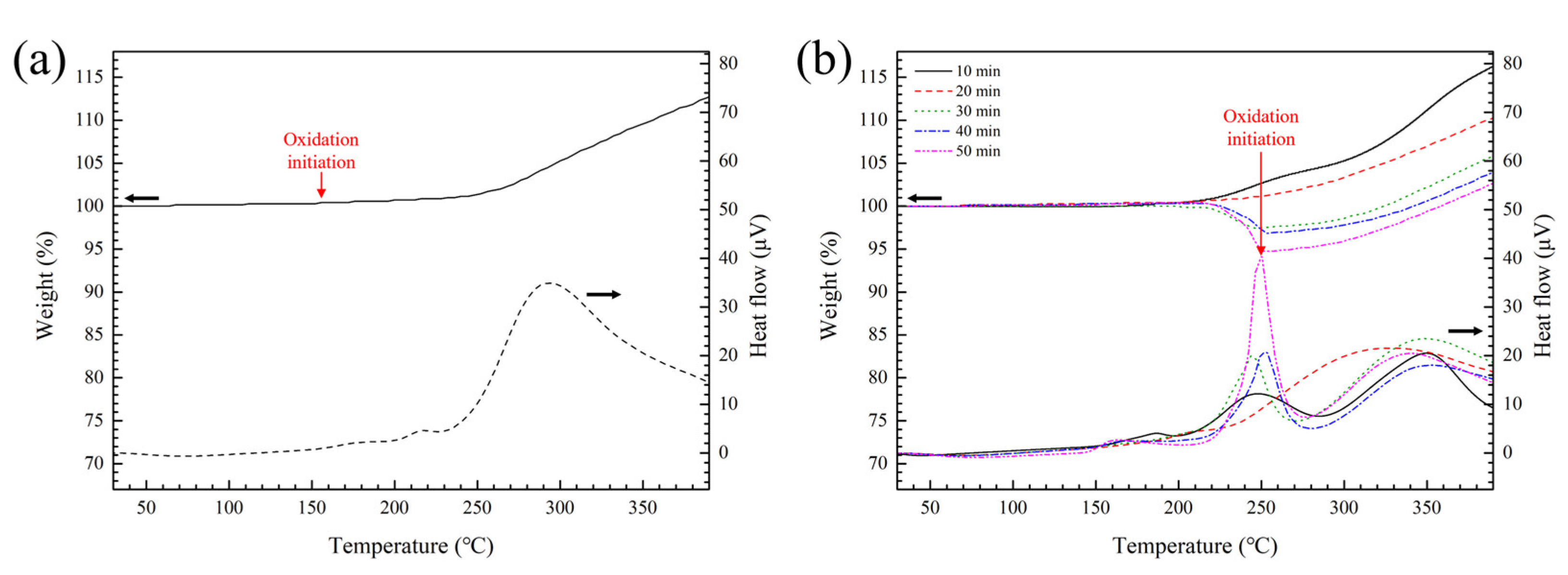
3.1. Characteristics of Cu Particles after Surface Treatment

Figure 2 shows the XRD results and Cu 2p and C 1s XPS spectra before and after surface treatment to monitor the phase transition and changes in the surface chemical states of the Cu particles. While the XRD results in Figure 2a indicate only pure Cu peaks before treatment, the Cu2O (111) peak at 36.4° appeared after the 20 min treatment. Subsequently, additional peaks of the copper formate (Cu(COOH)2) phase were detected with the extinction of the Cu2O peak after treatment for more than 30 min, and the intensity of the peaks increased over time. Meanwhile, the Cu 2p3/2 XPS spectra (Figure 2b) before and after treatment indicated a peak at 934.3 eV attributed to Cu–O bonding as well as a peak at 932.6 eV corresponding to the contribution of neutral-state Cu [33]. However, the intensity of the 934.3 eV peak decreased after treatment. Moreover, a novel peak at 935.1 eV was detected after treatment, which was attributed to Cu–COOH bonding [31]. In the C 1s spectra of Figure 2b, a 286.24 eV peak of COO bonding together with a 288.42 eV peak corresponding to the COOH bonding were observed after treatment [34]. These results imply the formation of a copper formate and the loss of Cu oxides on the particle surfaces after surface treatment [31].
Figure 3 shows the surface SEM image, cross-sectional TEM image, and fast Fourier transform (FFT) diffraction patterns of Cu particles with different treatment times using formic acid. Before treatment (Figure 3a), the Cu particles had smooth surfaces of CuO in particulate form. After treatment for 10 min (Figure 3b), the Cu particle surface maintained a smooth state at low magnification; however, nanoscale surface roughness was observed at high magnification in the form of a nanosized copper formate seed layer through Equation (1) [35]. Furthermore, following the subsequent reaction of Equation (2) with the addition of Cu2O, the thickness of the copper formate layer increased with an increase in the treatment time to 50 min (Figure 3c) [36]. The particle surface exhibited adequate coverage by the copper formate layer with an increased surface roughness. Cross-sectional TEM images of a particle after treatment (Figure 3d) and its fast Fourier transform (FFT) patterns (Figure 3e) provide clear evidence of the formation of a copper formate layer. The copper formate layer formed a conformal coating on the core Cu particles, and the layer thickness was approximately 70 nm. Crystalline phases of Cu (111), Cu2O (111), and copper formate ( 1 1 ¯ 0 ) (001) ( 2 2 ¯ 1 ) were detected.
CuO + 2HCOOH → Cu(COOH)2 + H2O
Cu2O + 2HCOOH → Cu + Cu(COOH)2 + H2O
While the decomposition of copper formate layers generates pure Cu atoms to enhance sinterability between particles, the layer may also inhibit Cu oxidation until it decomposes during heating in air. TG-DTA was performed to examine the decomposition temperature and confirm oxidation inhibition, and the results are shown in Figure 4. Before surface treatment (Figure 4a), the Cu particles exhibited a gradual weight increase from 156 °C with heat generation owing to oxidation. In this study, the point of weight gain was defined as a 0.1% increase compared to the initial weight. Meanwhile, the surface-treated Cu particles produced different TG-DTA results depending on the surface treatment time, as shown in Figure 4b. The results for the Cu particles surface-treated for 10 to 20 min were similar to those for the non-treated particles. Meanwhile, the behaviors of the Cu particles surface-treated for 30 to 50 min were completely different in both TG and DTA, indicating that the Cu particles were well coated with sufficient thicknesses of copper formate layers in that case. Therefore, the Cu particles well-covered with copper formate layers did not exhibit a significant weight increase until they exceeded 200 °C, which implies that the formed copper formate layers provided oxidation resistance to the core Cu thanks to the surface coverage until decomposition. Consequently, the results in Figure 4b indicate again that the addition method of Cu2O was very successful in enhancing the growth of the copper formate layer and the coverage of the copper formate shells. The copper formate layer eventually decomposed from approximately 220 °C, generating active Cu atoms using Equation (3) [36]. This decomposition beginning temperature was similar to the result of a previous similar measurement [37], and it appeared to be somewhat delayed compared to the result measured at a relatively low heating rate of 10 °C/min [36].
Cu(COOH)2 → Cu + 2CO2↑ + H2
The exothermic peak formed at an identical temperature is attributed to sintering between the reduced Cu, indicating a peak temperature of 250 °C [38]. The stable emission of carbon dioxide and hydrogen gases generated during decomposition is considered beneficial for the temporal suppression of Cu oxidation. The observed TG-DTA results indicate that copper formate layers hinder the oxidation of Cu particles until their decomposition and normal oxidation behavior proceeds at temperatures exceeding 250 °C after the decomposition. However, late oxidation can also be suppressed if sintering between particles is rapidly performed under compression, as in our sinter bonding process.

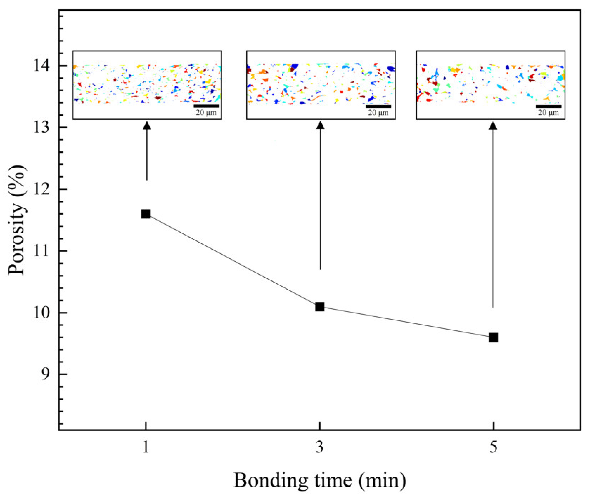
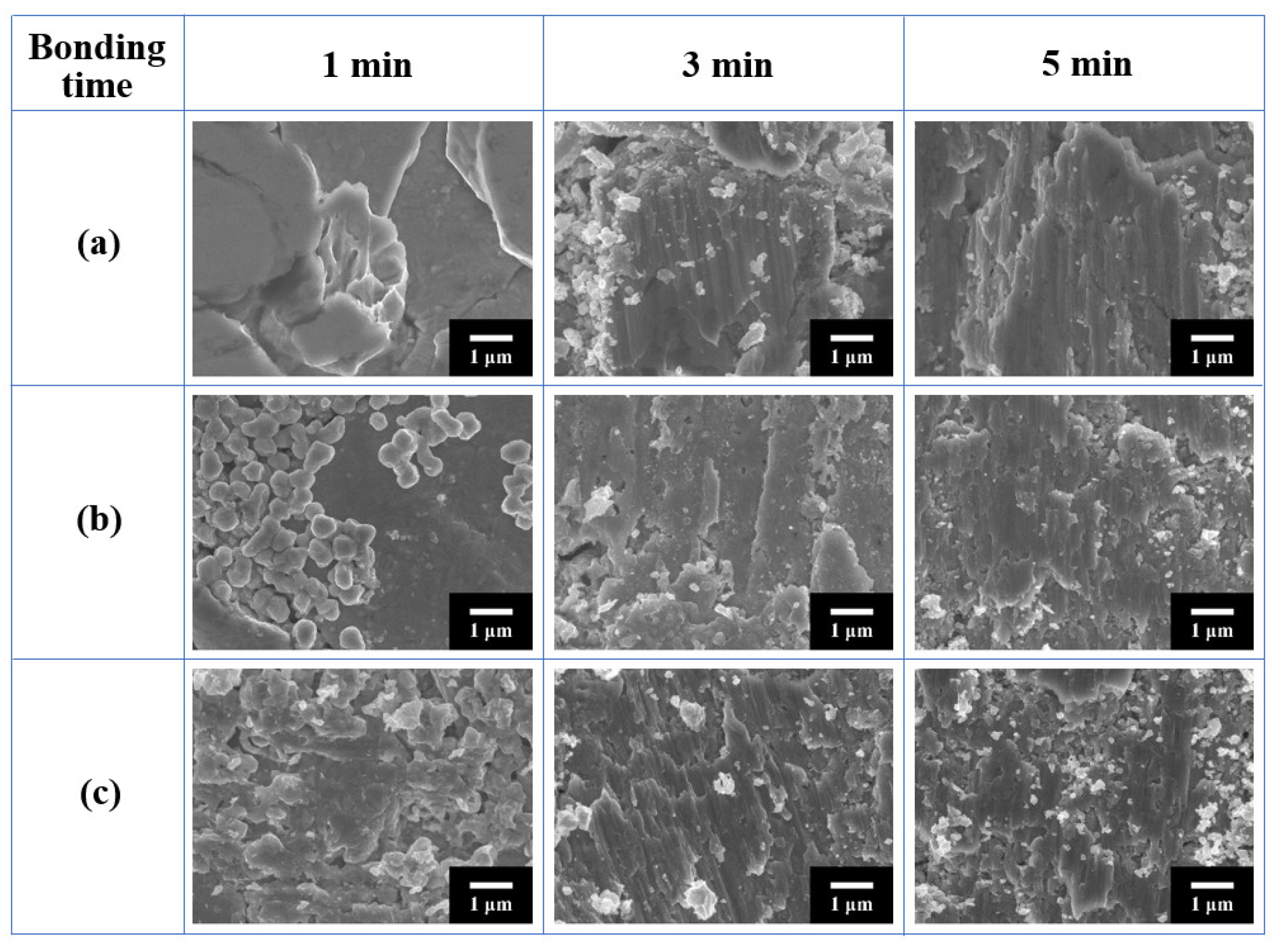
3.2. Bondline Microstructures

Figure 5 shows cross-sectional BSE images of the upper interfaces of the bondlines formed under 5 MPa compression using the SM paste at varying bonding temperatures and times. In the bonding at 300 °C, the bondlines that sinter-bonded for 1 to 3 min did not indicate well-sintered microstructures. In a 5 min bonding sample (Figure 5a), however, sintering between the Cu flakes and Cu finish/Cu flake interfaces was observed with a high sinterability of fresh Cu generated in situ by the decomposition of copper formate, which accomplished Cu-Cu bonding through the Cu bondline. Despite the presence of interparticle voids in the bondline and thinly oxidized Cu layers at some interfaces between the flakes and exposed Cu surfaces, bonding at the chip/bondline interface was confirmed by microstructural observations. Therefore, the intended inter-bonding strategy was successful. As shown in Figure 5b, aggregates of Cu nanoparticles formed by the thermal decomposition of copper formate layers were also clearly observed. When the bonding temperature was raised to 350 °C (Figure 5c–e), sinter bonding was achieved even by 1 min bonding, and the density in the bondline gradually increased with increasing time. The change in porosity in the bondline with bonding time is presented in Figure 6. At 1 min bonding, porosity reached 11.6%; however, as bonding time increased to 3 min and 5 min, porosity decreased to 10.1% and 9.6%, respectively. Furthermore, the oxidized areas at the interfaces between the flakes expanded with increasing bonding time in the porous structure of the bondline before reaching full density. The bondline microstructures in the 1 min bonding sample (Figure 5c) were similar to those (Figure 5a) after 5 min bonding at 300 °C. When the bonding time was increased to 3 and 5 min, oxidation gradually advanced on the exposed Cu surfaces, but the degree of sintering by interdiffusion between the Cu particles and between the Cu finish/Cu particle interfaces increased significantly, resulting in a gradual reduction in porosity in the bondline.
Figure 7 shows cross-sectional BSE images of the upper interfaces of the bondlines formed using the BM paste with respect to the bonding temperature and time. Compared to the SM paste samples, the BM paste samples indicated initial uniform packing factors, which induced near-full-density bondline structures from only 3 min of bonding at both 300 °C and 350 °C. Meanwhile, in the 1 min bonding bondlines (Figure 7a,d), the added 350 nm Cu particles provided a highly scattered partial sintering with an enlarged contact area between the particles. However, the scattered 350 nm Cu particles interrupted the mature sintering between Cu flakes, which could account for the 11.5 MPa and 14.2 MPa shear strengths. The 3 min bonding bondline at 300 °C (Figure 7b) presented a near-full-density microstructure, and the distribution of Cu oxide layers (the darker gray area) at interfaces between the particles and the Cu finish/Cu flakes interfaces was also observed. During the sintering process in air, oxygen that has penetrated from the outside through the particles that have not been densified oxidizes the surfaces of particles inside the bondline. The surface oxidation greatly inhibits the sinterability of Cu particles. In the microstructure in Figure 7b, while coarsened Cu grains by effective sintering exist (refer to rectangular region 2), it is observed that dark-gray color of Cu oxide is distributed around Cu grains (refer to rectangular region 1 and 2) as a barrier. Subsequently, the 5 min bonding bondline (Figure 7c) did not cause a significant microstructural change. Again, these high-density bondlines were completely different from the microstructures obtained using the SM paste that consisted of only Cu flakes. Meanwhile, the 1 min bonding at 350 °C (Figure 7d) showed slightly improved sintering results between particles and at the particle/chip interfaces compared to the bondline at 300 °C for the same bonding time. However, the 3 min bonding bondline at 350 °C (Figure 7e) exhibited an extensive generation of oxidized Cu owing to the high temperature. In the subsequent 5 min bonding bondline (Figure 7f), the Cu oxide phase slightly expanded with the intensified oxidation of the particles. Figure 7g,h show the black-and-white images of Figure 7e and Figure 7f, respectively, produced by image processing. The original dark gray area, namely the oxide area, has been converted to black, and the black areas in the 3 min and 5 min bonded bondlines were measured to be 60.4% and 68.4%, respectively, confirming a continuous growth of the oxide phase with increasing bonding time.

3.3. Shear Strength of Bondlines

Figure 8 shows the average shear strength values for bondlines formed as a function of bonding temperature and time using the two types of paste under compression of 5 MPa. While all the sintered bondlines exhibited increased strength with increasing bonding time, each trend varied according to the paste type and bonding temperature. For the bondline by SM paste at 300 °C, the shear strength could not be measured until 3 min of bonding owing to inadequate sintering, while it reached 19.7 MPa after 5 min of bonding. However, when the bonding temperature was increased to 350 °C, the shear strength approached 18.9 MPa even after 1 min of bonding, which indicated a significant improvement in sinterability by Cu diffusion that increases sharply from 300 °C. The subsequent 3 min bonding provided an excellent shear strength of 26.3 MPa owing to the increased bondline density. When the bonding time was increased to 5 min, the strength increased slightly to 27.1 MPa because of the additional increase in bondline density under the increased Cu oxidation, as explained in Figure 6. Wu et al. prepared a paste using multi-scale Cu particles that were composed of spherical NPs (20–60 nm), submicrometer-particles (0.2–0.6 µm), and micro-particles (1–2 µm) and performed a 5 MPa compression sinter bonding with real Si chips and direct-bond copper (DBC) substrates [39]. To acquire a shear strength of 23.8 MPa, they adopted a slow heating rate of 10 °C/min and a long bonding time of 30 min at 300 °C even in Ar/H2 mixed gas [39]. Wang et al. prepared a paste by mixing lactic acid-treated Cu nanoparticles with an average diameter of 100 nm and 3-dimethylamino-1,2-propanediol and conducted a 4 MPa compression sinter bonding in air using Cu cylinders [40]. As a result, a shear strength of approximately 21.5 MPa was obtained by bonding for 400 s at 225 °C after maintaining for 3.5 min at 100 °C [40]. Son et al. prepared a bimodal Cu paste by mixing 1 µm Cu particles, 0.3 µm Cu particles, and polyethylene glycol-based solvent and carried out a 5 MPa compression sinter bonding for 1 min at 280 °C between Cu dummy chips with Au finish and DBC substrates [41]. With the suppression of Cu oxidation through processing in a vacuum, a high shear strength of approximately 30.5 MPa was achieved [41]. Liu et al. prepared a paste by mixing carboxylic acid-treated quasi-nanoparticles, ethylene glycol, and terpilenol and obtained a high shear strength of 36.5 MPa after a 5 MPa compression sinter bonding for 3 min at 250 °C in nitrogen with Cu dummy chips and DBC substrates [42]. In comparison with these results, the shear strength result of 18.9 MPa after 1 min bonding in air atmosphere achieved in this study implies that Cu particles well surface-treated with formic acid can provide a high sintering speed and decent sinterability by suppressing Cu oxidation.
Meanwhile, for bondlines formed by BM paste at 300 °C, 1 min bonding showed a low strength of 11.5 MPa owing to incomplete sintering. However, a bonding time of 3 min or longer resulted in sufficient strength, exceeding 21 MPa. Although a near-full-density bondline was formed from 3 min of bonding, the strength values were lower than those (26.3–27.1 MPa) of the 300 °C SM paste bonding because of the lack of effective sintering between the particles due to the relatively low temperature of 300 °C and the existence of oxide layers between the Cu particles. The bondline obtained by 1 min bonding after raising the temperature to 350 °C presented an insufficient strength of 14.2 MPa; however, subsequent 3 and 5 min bondings showed a gradual increase in strength to 21 MPa with an extensive distribution of oxide phases. Consequently, complete sintering between the flake particles was more effective in improving the robustness of the bondline than the packing factor improvement effect with the addition of 350 nm sized pure Cu particles. The addition of the 350 nm sized Cu particles was effective in improving sinterability in the early stage of sintering; however, they were quickly oxidized during sintering in air, thereby hindering an effective sintering between the Cu particles. As a result, the mechanical robustness of the bondline where the oxidized 350 nm sized Cu particles had been interposed between the Cu flakes was analyzed to be low while very dense bondlines were observed after compression sintering for more than 3 min.
An analysis of the mechanical properties in Figure 8 was attempted again through fracture analysis. Figure 9 displays fracture surface images of bondlines formed at different bonding temperatures and times. Except for the bondline/substrate interface failure in the 1 min and 3 min samples of 300 °C bonding using SM paste, all the fracture paths in the other samples were generated within the bondline. When comparing only the 1 min bonding fracture surfaces, all showed somewhat insufficient sintering. In the case of the SM fracture surface, sintering between the Cu flakes was observed, while in the case of the BM fracture surfaces, 350 nm sized Cu particles were sintered, hindering sintering between the Cu flakes (of course, the 350 °C bonding specimen was more sintered than the 300 °C bonding specimen). Subsequently, when comparing only the 3 min bonding fracture surfaces, quite well-sintered structures were indicated, such as striation fracture structures formed by shearing, but messy debris was observed as the Cu oxide phases fell off. In the case of the SM fracture surface, interparticle voids were observed, but sintering between flakes seemed to be strong and oxide debris was mainly distributed near the voids; however, in the case of the BM fracture surfaces, there were more complex fracture structures as the 350 nm sized Cu particles fell off and oxide debris was distributed across the entire fracture surface. Finally, when looking at the 5 min bonding fracture surfaces, in the case of the SM fracture surface, sintering between flakes seemed to be stronger and oxide debris was distributed locally. In contrast, in the case of the BM fracture surfaces, although the densities of fracture surfaces were significantly high, more complex fracture structures were observed owing to the influence of the 350 nm sized Cu particles and oxide debris distributed across the entire fracture surface. Through these fracture structure analysis results, it was confirmed that in the case of the BM samples, the oxidation of the 350 nm sized Cu particles greatly reduced the mechanical robustness of the bondline, which led to a decrease in shear strength.

4. Conclusions

For a next-generation chip attachment by sinter bonding in air, a paste containing Cu-copper formate core-shell flakes was prepared, and thermo-compression bonding was conducted between low-cost Cu finishes. Thick copper formate shells of approximately 70 nm were formed after an immersion of the flakes, together with Cu2O nanoparticles as a precursor, in a dilute formic acid solution for 50 min. The formation of the copper formate shells was confirmed by XRD, XPS, and TEM analyses. Moreover, TG-DTA results showed both the decomposition of the copper formate layers from approximately 220 °C and sintering between generated Cu atoms related to the peak at 250 °C. The sinter bonding in air using the flakes under a compression of 5 MPa exhibited a sufficient shear strength of 18.9 and 26.3 MPa after only 1 and 3 min at 350 °C, respectively, despite the retention of big interparticle voids and local oxidation in the bondline. This fast sinter bonding result even in air indicates a suppression of Cu oxidation by the formate shells and a superior sinterability of active Cu in situ generated by the thermal decomposition of the shells. Consequently, the coverage by sufficient thicknesses of copper formate layers greatly reduced the disadvantage of micrometer-sized Cu filler in sinter-bonding paste. The addition of 350 nm size pure Cu particles filled the interparticle voids and generated a near-full-density bondline within 3 min. Meanwhile, the shear strength values in the bondlines were less than 26.3 MPa due to severe oxidation in the added Cu particles that prevented sintering between the particles.

Author Contributions

Conceptualization, W.L.C. and J.-H.L.; methodology, W.L.C. and J.-H.L.; validation, W.L.C. and J.-H.L.; formal analysis, J.-H.L.; investigation, W.L.C. and J.-H.L.; resources, W.L.C. and J.-H.L.; data curation, W.L.C.; writing—original draft preparation, W.L.C. and J.-H.L.; writing—review and editing, J.-H.L.; visualization, W.L.C.; supervision, J.-H.L.; project administration, J.-H.L.; funding acquisition, J.-H.L. All authors have read and agreed to the published version of the manuscript.

Funding

This study was supported by the Research Program (U2022-0230) funded by SeoulTech (Seoul National University of Science and Technology).

Data Availability Statement

Data available on request from the authors.

Conflicts of Interest

The authors declare no conflict of interest. The funders had no role in the design of the study; in the collection, analyses, or interpretation of data; in the writing of the manuscript; or in the decision to publish the results.

References

  1. Roccaforte, F.; Fiorenza, P.; Greco, G.; Nigro, R.L.; Giannazzo, F.; Lucolano, F.; Saggio, M. Emerging trends in wide band gap semiconductors (SiC and GaN) technology for power devices. Microelectron. Eng. 2018, 187–188, 66–77. [Google Scholar] [CrossRef]
  2. Chen, T.F.; Siow, K.S. Comparing the mechanical and thermal-electrical properties of sintered copper (Cu) and sintered silver (Ag) joints. J. Alloys Compd. 2021, 866, 158783. [Google Scholar] [CrossRef]
  3. Mei, Y.H.; Wang, Z.; Siow, K.S. Reliability and failure mechanisms of sintered silver as die attach joint. In Die-Attach Materials for High Temperature Applications in Microelectronics Packaging; Siow, K.S., Ed.; Springer: Cham, Switzerland, 2019; pp. 125–150. [Google Scholar]
  4. Yoon, J.-W.; Back, J.-H. Effect of sintering conditions on the mechanical strength of Cu-sintered joints for high-power applications. Materials 2018, 11, 2105. [Google Scholar] [CrossRef] [PubMed]
  5. Durand, C.; Klingler, M.; Bigerelle, M.; Coutellier, D. Solder fatigue failures in a new designed power module under power cycling. Microelectron. Reliab. 2016, 66, 112–133. [Google Scholar] [CrossRef]
  6. Zhang, Z.; Chen, C.; Yang, Y.; Zhang, H.; Kim, D.; Sugahara, T.; Nagao, S.; Suganuma, K. Low-temperature and pressureless sinter joining of Cu with micron/submicron Ag particle paste in air. J. Alloys Compd. 2019, 780, 435–442. [Google Scholar] [CrossRef]
  7. Sun, S.; Guo, Q.; Chen, H.; Li, M.; Wang, C. Solderless bonding with nanoporous copper as interlayer for high-temperature applications. Microelectron. Reliab. 2018, 80, 198–204. [Google Scholar] [CrossRef]
  8. Chen, G.; Yu, L.; Mei, Y.H.; Li, X.; Chen, X.; Lu, G.Q. Reliability comparison between SAC305 joint and sintered nanosilver joint at high temperatures for power electronic packaging. J. Mater. Process Technol. 2014, 214, 1900–1908. [Google Scholar] [CrossRef]
  9. Tan, K.S.; Wong, Y.H.; Cheong, K.Y. Thermal characteristic of sintered Ag-Cu nanopaste for high-temperature die-attach application. Int. J. Therm. Sci. 2015, 87, 169–177. [Google Scholar] [CrossRef]
  10. Choi, E.B.; Lee, J.-H. Tens-of-seconds solid-state sinter-bonding technique in air using in situ reduction of surface oxide layers on easily bendable dendritic Cu particles. Appl. Surf. Sci. 2022, 580, 152347. [Google Scholar] [CrossRef]
  11. Mohan, K.; Shahane, N.; Raj, P.M.; Antoniou, A.; Smet, V.; Tummala, R. Low-Temperature, Organics-Free Sintering of Nanoporous Copper for Reliable, High-Temperature and High-Power Die-Attach Interconnections. In Proceedings of the 2017 IEEE Applied Power Electronics Conference and Exposition (APEC), Tampa, FL, USA, 26–30 March 2017; IEEE: Manhattan, NY, USA, 2017. [Google Scholar]
  12. Peng, P.; Hu, A.; Gerlich, A.P.; Zou, G.; Liu, L.; Zhou, Y.N. Joining of silver nanomaterials at low temperatures: Processes, properties, and applications. ACS Appl. Mater. Interfaces 2015, 7, 12597–12618. [Google Scholar] [CrossRef]
  13. Jianfeng, Y.; Guisheng, Z.; Anming, H.; Zhou, N. Preparation of PVP coated Cu NPs and the application for low-temperature bonding. J. Mater. Chem. 2012, 21, 15981. [Google Scholar] [CrossRef]
  14. Morita, T.; Ide, E.; Yasuda, Y.; Hirose, A.; Kobayashi, K. Study of bonding technology using silver nanoparticles. Jpn. J. Appl. Phys. 2008, 47, 6615–6622. [Google Scholar] [CrossRef]
  15. Ma, H.; Suhling, J.C. A review of mechanical properties of lead-free solders for electronic packaging. J. Mater. Sci. 2009, 44, 1141–1158. [Google Scholar] [CrossRef]
  16. Suganuma, K.; Kim, S.-J.; Kim, K.-S. High-temperature lead-free solders: Properties and possibilities. JOM 2009, 61, 64–71. [Google Scholar] [CrossRef]
  17. Soichi, S.; Suganuma, K. Low-temperature and low-pressure die bonding using thin Ag-flake and Ag-particle pastes for power devices. IEEE Trans. Compon. Packag. Manuf. Technol. 2013, 3, 923. [Google Scholar] [CrossRef]
  18. Kim, M.I.; Lee, J.-H. Die sinter bonding in air using Cu@Ag particulate preform and rapid formation of near-full density bondline. J. Mater. Res. Technol. 2021, 14, 1724–1738. [Google Scholar] [CrossRef]
  19. Ide, E.; Angata, S.; Hirose, A.; Kobayashi, K.F. Metal-metal bonding process using Ag metallo-organic nanoparticles. Acta Mater. 2005, 53, 2385–2393. [Google Scholar] [CrossRef]
  20. Yan, J.; Zhang, D.; Zou, G.; Liu, L.; Bai, H.; Wu, A.; Zhou, Y.N. Sintering bonding process with Ag nanoparticle paste and joint properties in high temperature environment. J. Nanomater. 2016, 2016, 5284048. [Google Scholar] [CrossRef]
  21. Wang, Q.; Zhang, S.; Lin, T.; Zhang, P.; He, P.; Paik, K.W. Highly mechanical and high-temperature properties of Cu–Cu joints using citrate-coated manosized Ag paste in Air. Prog. Nat. Sci. 2021, 31, 129–140. [Google Scholar] [CrossRef]
  22. Iijima, J.; Lim, J.W.; Hong, S.H.; Suzuki, S.; Mimura, K.; Isshiki, M. Native oxidation of ultra high purity Cu bulk and thin films. Appl. Surf. Sci. 2006, 253, 2825–2829. [Google Scholar] [CrossRef]
  23. Fehlner, F.P.; Mott, N.F. Low-temperature oxidation. Oxid. Met. 1970, 2, 59–99. [Google Scholar] [CrossRef]
  24. Aromaa, J.; Kekkonen, M.; Mousapour, M.; Jokilaakso, A.; Lundström, M. The Oxidation of copper in air at temperatures up to 100 °C. Corros. Mater. Degrad. 2021, 2, 625–640. [Google Scholar] [CrossRef]
  25. Zuo, Y.; Carter-Searjeant, S.; Green, M.; Mills, L.; Mannan, S.H. High bond strength Cu joints fabricated by rapid and pressureless in situ reduction-sintering of Cu nanoparticles. Mater. Lett. 2020, 276, 128260. [Google Scholar] [CrossRef]
  26. Li, W.; Li, L.; Gao, Y.; Hu, D.; Li, C.-F.; Zhang, H.; Jiu, J.; Nagao, S.; Suganuma, K. Highly conductive copper films based on submicron copper particles/copper complex inks for printed electronics: Microstructure, resistivity, oxidation resistance, and long-term stability. J. Alloys Compd. 2018, 732, 240–247. [Google Scholar] [CrossRef]
  27. Liu, X.; Nishikawa, H. Low-pressure Cu-Cu bonding using in-situ surface-modified microscale Cu particles for power device packaging. Scr. Mater. 2016, 120, 80–84. [Google Scholar] [CrossRef]
  28. Peng, Y.; Mou, Y.; Liu, J.; Chen, M. Fabrication of high-strength Cu–Cu joint by low-temperature sintering micron–nano Cu composite paste. J. Mater. Sci. 2020, 31, 8456–8463. [Google Scholar] [CrossRef]
  29. Li, J.J.; Cheng, C.L.; Shi, T.L.; Fan, J.H.; Yu, X.; Cheng, S.Y.; Liao, G.L.; Tang, Z.R. Surface effect induced Cu-Cu bonding by Cu nanosolder paste. Mater. Lett. 2016, 184, 193–196. [Google Scholar] [CrossRef]
  30. Li, J.; Liang, Q.; Shi, T.; Fan, J.; Gong, B.; Feng, C.; Fan, J.; Liao, G.; Tang, Z. Design of Cu nanoaggregates composed of ultra-small Cu nanoparticles for Cu-Cu thermocompression bonding. J. Alloys Compd. 2019, 772, 793–800. [Google Scholar] [CrossRef]
  31. Kim, I.; Kim, Y.; Woo, K.; Ryu, E.-H.; Yon, K.-Y.; Cao, G.; Moon, J. Synthesis of oxidation-resistant core-shell copper nanoparticles. RSC Adv. 2013, 3, 15169–15177. [Google Scholar] [CrossRef]
  32. Schwarzer, C.; Chew, L.M.; Schnepf, M.; Stoll, T. Investigation of Copper Sinter Material for Die Attach. In Proceedings of the SMTA International, Rosemont, IL, USA, 14–18 October 2018; SMTA: San Jose, CA, USA, 2018. [Google Scholar]
  33. Diaz-Droguett, D.E.; Espinoza, R.; Fuenzalida, V.M. Copper nanoparticles grown under hydrogen: Study of the surface oxide. Appl. Surf. Sci. 2011, 257, 4597–4602. [Google Scholar] [CrossRef]
  34. Cano, E.; Torres, C.L.; Bastidas, J.M. An XPS study of copper corrosion originated by formic acid vapor at 40% and 80% relative humidity. Mater. Corros. 2001, 52, 667–676. [Google Scholar] [CrossRef]
  35. Woo, K.; Kim, Y.; Lee, B.; Kim, J.; Moon, J. Effect of carboxylic acid on sintering of inkjet-printed copper nanoparticulate films. ACS Appl. Mater. Interfaces 2011, 3, 2377–2382. [Google Scholar] [CrossRef] [PubMed]
  36. Choi, W.L.; Kim, Y.S.; Lee, K.S.; Lee, J.-H. Characterization of the die-attach process via low-temperature reduction of Cu formate in Air. J. Mater. Sci. 2019, 30, 9806–9813. [Google Scholar] [CrossRef]
  37. Lee, Y.-J.; Lee, J.-H. Die Sinter bonding in air using copper formate preform for formation of full-density bondline. Trans. Nonferrous Met. Soc. China. 2021, 31, 1717–1728. [Google Scholar] [CrossRef]
  38. Gao, Y.; Zhang, H.; Li, W.; Jiu, J.; Nagao, S.; Sugahara, T.; Suganuma, K. Die bonding performance using bimodal Cu particle paste under different sintering atmospheres. J. Electron. Mater. 2017, 46, 4575–4581. [Google Scholar] [CrossRef]
  39. Wu, L.; Qian, J.; Zhang, F.; Yu, J.; Wang, Z.; Guo, H.; Chen, X. Low-temperature sintering of Cu/functionalized multiwalled carbon nanotubes composite paste for power electronic packaging. IEEE Trans. Power Electron. 2022, 37, 1234–1243. [Google Scholar]
  40. Wang, X.; Zhang, Z.; Feng, Y.; Xiao, F. Anti-oxidative copper nanoparticle paste for Cu–Cu bonding at low temperature in air. J. Mater. Sci. Mater. Electron. 2022, 33, 817–823. [Google Scholar] [CrossRef]
  41. Son, J.; Yu, D.-Y.; Kim, Y.-C.; Byun, D.; Bang, J. Effect of bimodal Cu paste on interfacial properties and mechanical strength of sintered joints. J. Electron. Mater. 2022, 51, 7326–7336. [Google Scholar] [CrossRef]
  42. Liu, X.; Li, S.; Fan, J.; Jiang, J.; Liu, Y.; Ye, H.; Zhang, G. Microstructural evolution, fracture behavior and bonding mechanisms study of copper sintering on bare DBC substrate for SiC power electronics packaging. J. Mater. Res. Technol. 2022, 18, 1407–1421. [Google Scholar] [CrossRef]
Figure 1. Schematic illustrations of (a) the surface treatment procedure of Cu flakes and (b) the sinter bonding procedure.
Metals 13 01516 g001
Figure 2. (a) XRD patterns of Cu flakes surface-treated for different times, (b) XPS spectra of Cu flakes before and after the 50 min surface treatment.
Metals 13 01516 g002
Figure 3. SEM images of the surface of (a) initial Cu flakes and Cu flakes after surface treatment for (b) 10 min and (c) 50 min. (d) Cross-section TEM image and (e) FFT pattern of the surface of 50 min surface-treated Cu flakes.
Metals 13 01516 g003
Figure 4. TG-DTA results for (a) the initial Cu flakes and (b) Cu flakes surface-treated for 10 to 50 min using formic acid.
Metals 13 01516 g004
Figure 5. Cross-section BSE images of the upper interfaces of bondlines sinter-bonded under 5 MPa compression in air using SM paste at different temperatures and times: (a) 300 °C—5 min, (b) high-magnification image of the black square from (a), (c) 350 °C—1 min, (d) 350 °C—3 min, and (e) 350 °C—5 min.
Metals 13 01516 g005
Figure 6. Porosities in cross-section BSE images of bondlines sinter-bonded under 5 MPa compression at 350 °C in air using SM paste with different bonding times.
Metals 13 01516 g006
Figure 7. Cross-section BSE images of the upper interfaces of bondlines sinter-bonded under 5 MPa compression in air using BM paste at different temperatures and times: (a) 300 °C—1 min, (b) 300 °C—3 min, (c) 300 °C—5 min, (d) 350 °C—1 min, (e) 350 °C—3 min, and (f) 350 °C—5 min. (g,h) Image processing results of (e,f).
Metals 13 01516 g007
Figure 8. Average shear strength of bondlines sinter-bonded under 5 MPa in air at different bonding temperatures and times using SM or BM paste.
Metals 13 01516 g008
Figure 9. Fracture surface images of bondlines sinter-bonded under 5 MPa in air at different bonding temperatures and times: (a) SM paste—350 °C, (b) BM paste—300 °C, and (c) BM paste—350 °C.
Metals 13 01516 g009
Disclaimer/Publisher’s Note: The statements, opinions and data contained in all publications are solely those of the individual author(s) and contributor(s) and not of MDPI and/or the editor(s). MDPI and/or the editor(s) disclaim responsibility for any injury to people or property resulting from any ideas, methods, instructions or products referred to in the content.

