Article

Study on the Deformation and Fracture Mechanisms of Plastic Metals Considering Void Damage

Faculty of Mechanical and Electrical Engineering, Kunming University of Science and Technology, Kunming 650500, China
*
Author to whom correspondence should be addressed.
Metals 2023, 13(9), 1566; https://doi.org/10.3390/met13091566
Submission received: 7 August 2023 / Revised: 31 August 2023 / Accepted: 1 September 2023 / Published: 6 September 2023
(This article belongs to the Special Issue Fatigue, Fracture and Damage of Steels)

Abstract

:
Fracture initiation in plastic metals is attributed to the development of voids. Analyzing the nucleation and growth processes of voids facilitates the study of plastic deformation and fracture mechanisms in metal materials. Uniaxial tensile tests were conducted on two high-quality carbon structural steels, and the microfracture surface morphology of the tensile specimens was observed by using a scanning electron microscope (SEM). From the perspective of vacancy condensation, the nucleation mechanism of voids in the absence of inclusions or particles was analyzed. Based on the continuum damage mechanics theory and the Rice–Tracy (R-T) model, a damage parameter considering the void volume fraction was derived, and a plastic potential function, hardening curve, and constitutive model for the plastic deformation process of the plastic metal material were established. Based on the uniaxial tensile test data of the two sheets of high-quality carbon steel, the strain range data in the hardening stage were converted into true stress–plastic strain data, and the established hardening curve was used to fit the true stress–plastic strain data. The results showed good agreement between the established hardening curve and the experimental results, which effectively reflected the deformation process of ductile fractures in plastic metal materials.

1. Introduction

Plastic metal materials are widely used in the structural components of large-scale equipment, such as giant ships, large oil storage devices, high-rise buildings, and important roads and bridges. While fully meeting the existing theoretical system of plastic metal strength, these important structural components still experience occasional catastrophic failure accidents. This has not only caused huge economic losses, but has also brought about certain casualties [1,2,3]. The reason for this is that the fracture mechanisms and related failure criteria of plastic metal materials still need further exploration and research. Therefore, further research on the fracture mechanisms and failure criteria of plastic metal materials still has important scientific value and practical significance for the in-depth exploration of the essence of sudden failures of large structural components and their safe application in various fields.
Previous researchers have conducted extensive research on the fracture mechanisms and related failure criteria of plastic metal materials. McClintock [4] studied the growth and coalescence of cylindrical voids under a given stress–strain action and established a ductile fracture criterion that considered the growth of voids. Argon et al. [5] theoretically derived the nucleation conditions of pores during the ductile fracture process. Based on this, Landron et al. [6] further considered the influence of stress triaxiality and established a model for the evolution of pore density during the fracture process of dual-phase steel; the obtained model was in good agreement with the experimental results. Beremin [7] conducted fracture tests on notched specimens of round rods made of A508 steel, which is used for pressure vessels in nuclear power plants. It was found that the nucleation mechanisms of pores in the short transverse and longitudinal directions were different during the fracture process. During longitudinal loading, the pores nucleated due to inclusion fractures, while in the short transverse direction, the particle–matrix interface peeled off, leading to the nucleation of pores. Le Roy et al. [8] studied the fracture behavior of four high-quality ordinary carbon steels and found that fractures of carbides and detachment from the matrix led to the nucleation of voids. They proposed a ductile fracture model based on the nucleation and growth mechanisms of voids. Ye et al. [9] used the cell analysis method to discuss the effects of stress triaxiality and the Lode parameter on the growth of voids in cells and constructed a ductile fracture model to more accurately describe the ductile fracture behavior of Q345 steel in complex stress states. Zhang et al. [10] used the third-generation ultra-high-strength QP1180 steel as the research object, designed five differently shaped material samples, and conducted fracture limit tests. Combined with finite element simulation technology, they established the Modified Mohr–Coulomb (MMC) fracture criterion and Generalized Incremental Stress-State-Dependent Model (GISSMO) for QP1180, effectively predicting the failure behavior of the material. The micromechanical damage model represented by the Gurson–Tvergard–Needlmann (GTN) model is widely used to describe the ductile fracture process of plastic metal materials [11,12,13]. Deng [14] took 304 stainless steel as the research object and obtained the GTN model damage parameters of the steel through a uniaxial tensile test. Jiang [15] proposed a GTN model with dual damage variables that can describe the shear failure behavior of plastic metal materials. Dong et al. [16] constructed a displacement-related damage function as a new fracture criterion based on Jiang [15]; the simulation results with this model were consistent with shear test results on SUS304 stainless steel pipes.
By observing the microscopic morphology of the fracture surface of plastic metal materials, it can be found that there are large numbers of dimples of the same scale distributed along the fracture direction in the cross-section. Maire et al. [17] studied the fracture process of DP600 through an in situ SEM tensile test and used X-ray tomography to explore the evolution of DP steel damage. It was found that the damage was caused by martensitic fracture and ferrite/martensite decohesion, and a large number of dimples with different sizes were observed at the fracture surface of the DP steel. Wu et al. [18] observed the fracture morphology of 45 steel in different stress states with SEM and found that there were dimples of varying sizes in the fracture surfaces of both standard and notched tensile specimens. Deng [14] observed the tensile fracture surfaces of two types of 304 stainless steel samples and found a large number of fracture dimples. The voids in the samples containing MnS inclusions preferentially nucleate at the inclusion and second-phase particles, while the morphology of the dimples on the fracture surface of the samples without MnS inclusions is mainly caused by shear stress. Yan et al. [19] used high-resolution 3D X-ray tomography technology to analyze the evolution process of microvoids in G20Mn5N low-alloy cast steel. The fracture morphology of the sample also displayed different sizes of dimples; the research results showed that the growth and coalescence of pores ultimately led to ductile fracture of the material. On the basis of the void growth model (VGM), Huang et al. [20] proposed a new fracture model named the LVGM model that comprehensively considered the effects of stress triaxiality and the Lode parameter. This model effectively predicted the fracture process of Q235B steel; the microstructure of the fracture surface showed equiaxial and shear dimples. Othmen et al. [21] conducted tensile fracture experiments on AISI304L stainless steel plates and investigated the ductile fracture behavior of AISI304L stainless steel using four different ductile fracture criteria. The numerical simulation results indicated that the Rice–Tracey or Brozzo fracture criteria can effectively predict the fracture behavior of AISI304L stainless steel. Additionally, a significant presence of dimples was observed on the fracture surface of the tensile specimens. This failure mode is believed to be induced by the formation of voids around non-metallic inclusions and/or second-phase particles within the metal matrix, which undergo continuous plastic deformation under an external load. The growth and coalescence of these voids ultimately lead to the fracture of the specimen. Tang et al. [22] investigated the failure behavior of hot-stamped 22MnB5 boron steel under various loading conditions. They incorporated three-point bending tests for calibration with a ductile fracture criterion. The numerical simulation results indicated that this model effectively predicted the macro-crack propagation under a circular punch. Additionally, SEM images indicated that there was a significant difference in the morphologies of ductile fractures under tensile stress and shear stress; there was a large number of dimples on the fracture surface of the tensile specimen, while there was a shear band with minor voids on the fracture surface of the shear specimen, and it was observed that the fracture surface was composed of waved structures in the direction of the maximum shear stress (MSS). Li et al. [23] employed an approach combining experiments and microstructure-based crystal plasticity simulations to elucidate the mechanism of plastic anisotropy in DP980 steel sheets. The uniaxial tensile specimen exhibited the typical fracture features of ductile metals, with the fracture surface displaying plentiful elongated shallow dimples, which indicated the dominance of shear fractures. Barnwal et al. [24] conducted hydraulic bulging tests on two advanced high-strength steels, DP980 and TRIP1180, to cause the biaxial fracture of the material. SEM fracture photos of bulging specimens of the two materials at different magnifications showed a large number of small dimples, and some dimples contained inclusions. Qian et al. [25] designed five fracture tests on high-strength TRIP780 steel sheets from shear to tensile stress states. The microstructure of the fracture surface consisted of dimples and shear bands. Based on this analysis, the fracture mechanisms of the material in different stress states were analyzed, and an MMC fracture criterion that could reflect the microfracture mechanism was established. The applicability of this criterion was verified through compression shear fracture tests. Marteleur et al. [26] studied the effects of different stress states on the nucleation of voids and the mechanism of ductile fracture in high-strength steel. The study showed that the nucleation of voids originated from the fracture of inclusions and two-phase particles or separation from the matrix material, and it was observed that some of the dimples still contained inclusions and two-phase particle residues. Ding et al. [27] studied the fracture performance of 316 L stainless steel. The tensile fracture morphology of 316 L stainless steel was mainly that of ductile dimples, which exhibited ductile fracture characteristics. The formation of ductile dimples was caused by dislocation aggregation and stress concentration, which were due to carbide particles behaving as strengthening phases. The fracture morphology of forged 316 L stainless steel not only includes dimple fractures, but also transcrystalline fractures. The fracture surface of 316 L stainless steel prepared with the direct energy deposition method was distributed with small, uniformly sized, and equiaxed dimples.
In summary, extensive studies have been conducted by numerous scholars on the nucleation, growth, and coalescence mechanisms of voids in plastic metal materials at inclusion or particle sites, as well as material fracture criteria. In this study, uniaxial tensile tests were performed on two types of plastic metal, and the microfracture surface morphologies of the specimens were observed using scanning electron microscopy (SEM). It was found that only one inclusion was present within a single tough dimple on the fracture surface, indicating that the nucleation mechanism of voids at inclusion or particle sites cannot explain the experimental phenomena observed in this study. Based on this experimental observation, the void nucleation mechanisms in plastic metals were analyzed under the conditions of no inclusions and particles. By combining the theory of continuum damage mechanics and the cavity growth model, a plastic potential function, hardening curve, and constitutive model describing the void volume fraction during the plastic deformation process of plastic metals were established. Furthermore, the experimental results were fitted with the hardening curve, exhibiting a high level of agreement between the two.

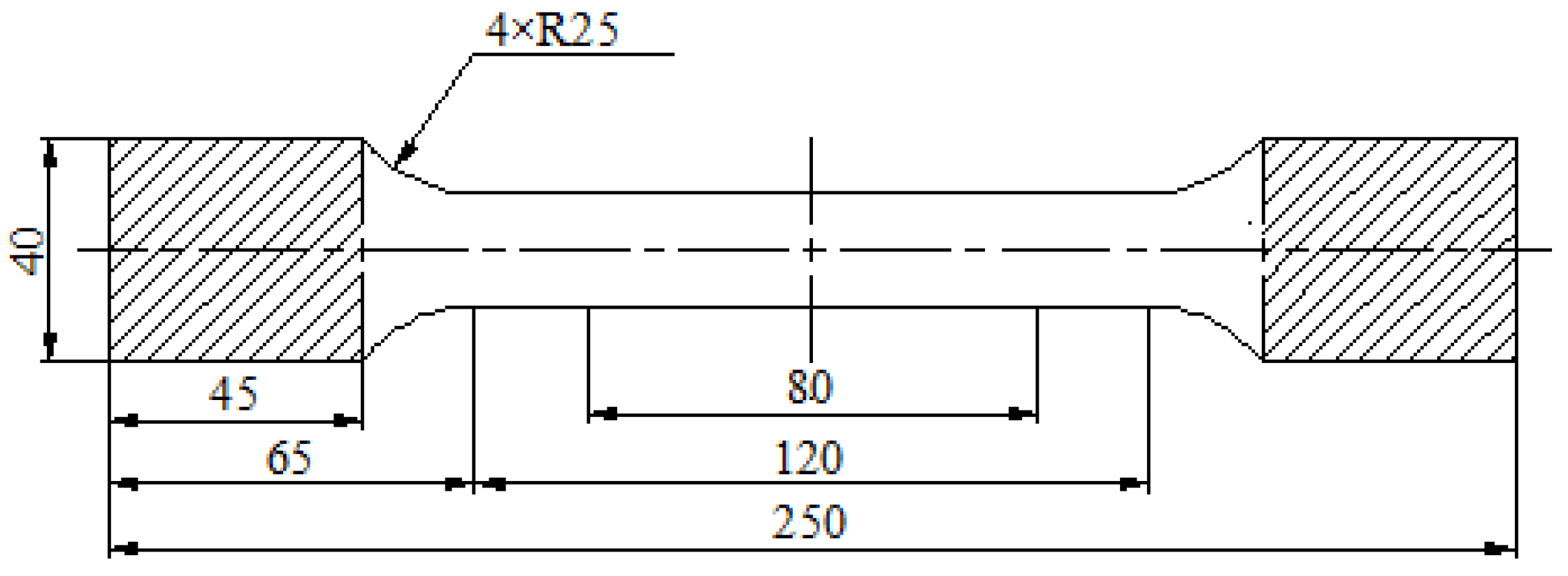
2. Materials and Experiments

This study conducted uniaxial tensile tests on two types of plastic metals obtained from different parts of automobiles. The dimensional data of the specimens used in the experiment are shown in Figure 1, and the thickness was 1 mm. Due to the difficulty in determining the specific grades of the selected materials, chemical composition analysis was performed on two elements, C and Mn, which had a significant impact on the mechanical properties of the materials. The specific analysis results are presented in Table 1. According to the stress–strain curve, it can be observed that neither of the two steel materials exhibited a distinct yield plateau, and the stress–strain relationship underwent a gradual transition from linear to nonlinear. Therefore, the stress value σ 0.2 at a strain of ε = 0.2 % was taken as the yield strength of the materials under investigation, and this was used to calculate the value of the elastic modulus. Furthermore, a comparison was made between the grades and chemical composition requirements of high-quality carbon structural steel plates and steel strips used in automobile manufacturing. The possible grades of the two steel materials were inferred, as shown in Table 2 and Table 3. Uniaxial tensile tests were conducted on a CSS-444100 electronic universal material testing machine with a test loading speed of 8 mm/min. The nominal stress–strain curves for the two steel materials were obtained through the tests, as depicted in Figure 2. The tensile mechanical properties and parameters are shown in Table 1. The fracture surface morphologies of the two specimens were observed using SEM at a magnification of 2000×, and the local fracture morphologies of the specimens were observed at a magnification of 5000×. The microfracture morphologies are shown in Figure 3.
At this scale, the fracture surface morphology exhibited numerous dimples of varying sizes, indicating a ductile fracture mode dominated by dimple rupture. However, within the fracture surface morphology at this scale, no particles or inclusions were found, as shown in Figure 3a,b. As shown in Figure 3c,d, only one inclusion was observed within a dimple, while no presence of particles or inclusions was detected in the remaining dimples. The experimental results indicate that the nucleation and growth of a large number of voids were primarily caused by the deformation of the matrix material, leading to the eventual ductile fracture of the material. Only a small fraction of the voids nucleated at inclusion sites.

3. Characterization of the Stress State

Assuming isotropic hardening of plastic metal materials during deformation, the stress state of a point within the plastic metal material can be characterized in terms of the stress triaxiality ( T ) and the Lode parameter ( μ σ ) in the principal stress coordinate system   ( σ 1 , σ 2 , σ 3 ) . The expression is as follows:
T = σ m σ e q = 3 I 1 9 J 2
μ σ = cos 3 θ = 27 J 3 2 σ e q = 3 3 2 J 3 J 2 3 / 2
where σ 1 , σ 2 , and σ 3 represent the principal stresses, σ m is the mean stress, σ e q is the von Mises stress, θ is the Lode angle, and I 1 , J 2 , and J 3 , which represent the first stress invariant and the second and third deviatoric stress invariants, respectively, are defined as follows:
σ e q = 3 2 S i j S i j
I 1 = 3 σ m = σ 1 + σ 2 + σ 3
J 2 = 1 6 [ σ 1 σ 2 2 + σ 1 σ 3 2 + σ 2 σ 3 2 ]
J 3 = σ 1 σ m σ 2 σ m σ 3 σ m

4. Mechanisms of Deformation and Ductile Fracture

4.1. The Mechanism of Void Nucleation

In order to investigate the fracture mechanisms of plastic metal materials, it is necessary to provide a reasonable explanation for the nucleation of voids. Rather than a mechanism of void nucleation at inclusions or particles, this study presents a nucleation mechanism of voids based on the experimental results from the perspective of vacancy condensation. Most metals have an equilibrium vacancy concentration of around 10−20 at room temperature. Plastic deformation leads to significant vacancy supersaturation, and the vacancy concentration c v in the plastic metal deformation process is directly proportional to the work done by external loads [28]:
c v = A G 0 ε σ d ε
where G is the shear modulus, σ and ε are the stress and strain, and A is a material-dependent constant between 0.1 and 1. According to Equation (7) and the stress–strain curve of the plastic metal in this study, it can be inferred that the vacancy concentration is approximately 10−4. The plastic deformation of plastic metal materials causes them to produce a supersaturated vacancy concentration. The material continuously hardens during the flow process, and the flow resistance increases. As there is no material flow to compensate for the voids generated by supersaturated vacancy concentration, the voids nucleate at the locations of vacancy condensation.

4.2. Ductile Damage Theory

The ductile fracture process of plastic metals is accompanied by significant plastic deformation, which is mainly characterized by the nucleation, growth, and coalescence of voids, ultimately resulting in ductile fracture. Based on the continuum thermodynamics theory, a plastic potential was proposed by Rousselier [29,30]. It is assumed that a dissipative potential function exists in the plastic deformation of plastic metal, and the plastic strain of the material satisfies the orthogonality rule with other internal variables. The thermodynamic potential for the plastic deformation process of plastic metals can be expressed as follows:
ψ = 1 2 ε i j e Λ i j k l ε k l e + ψ 1 p + ψ 2 β
The first term is the elastic recoverable energy, while the second and third terms represent the irreparable free energy (plastic energy and damage energy) related to dislocations, residual stress, voids, etc. p denotes the cumulative plastic strain, and β represents the damage variables related to the density of plastic metals. Therefore, the effective stress can be expressed in terms of the damage variable as follows:
σ ~ i j = σ i j 1 β
When there is no damage, the Von Mises form of the plastic potential is:
F σ i j ρ = 3 J 2 σ i j ρ P ( p )
where P ( p ) represents the hardening curve. After introducing the damage parameter associated with voids, the plastic potential in the plastic deformation process of the metal should be related to the spherical stress tensor. It is assumed that the plastic potential of the plastic metal in the stress space is given by:
F σ i j ρ = 3 J 2 σ i j ρ P p 3 Y g σ i j ρ
The plastic strain rate and stress are decomposed into the deviator tensor and spherical tensor:
ε ˙ i j p = e ˙ i j p + ε ˙ m p δ i j
σ i j = S i j + σ m δ i j
where e ˙ i j p is the deviator of ε ˙ i j p , and   S i j is the deviator of σ i j . From the above equation, the following can be concluded:
P = d ψ 1 p d p , Y = d ψ 2 β d β
e ˙ i j p = λ F S i j = 3 2 λ S i j σ e q
ε ˙ m p = λ F σ m = λ Y 3 d g σ m ρ d σ m ρ
p ˙ = λ = 2 3 e ˙ i j p e ˙ i j p
β ˙ = 3 λ g σ m ρ
According to Equation (11), the hardening curve of plastic metals can be obtained:
σ e q ρ d ψ 1 p d p d ψ 2 β d β g σ m ρ = 0
According to Equation (16), the function g σ m ρ is related to plastic volume deformation. Neglecting the variations in volume due to elastic deformations, according to the mass conservation law, the following equation is obtained:
d i v   V = 3 ε ˙ m 3 ε ˙ m p
where V is the volume change in plastic deformation. The mass conservation law can be written as follows:
ρ ˙ + 3 ρ ε ˙ m p = 0
Because the damage variable β is a function of ρ , there is:
β ˙ = d β d ρ ρ ˙
Substituting Equation (22) into Equation (21), parallel Equations (16) and (18) can be used to obtain:
1 g σ m ρ d g σ m ρ d σ m ρ = 1 Y ρ d β d ρ
The two sides of Equation (23) are functions of distinct variables: σ m ρ and β ; they are, therefore, equal to a constant, the dimension of which is the reciprocal of the stress and is called C 1 σ s , where σ s is the yield stress. The integration of the left-hand side leads to:
g σ m ρ = C 2 exp C 1 σ m σ s ρ
where C 2 is the constant of integration. Damage occurs in plastic metals after plastic deformation, making it irreversible. In order that damage increases with the stress triaxiality and that β ˙ > 0 , it is required that constants C 1 and C 2 are sup positive. Based on Equations (18) and (24), we can obtain:
β ˙ = λ C 2 exp C 1 σ m σ s ρ

4.3. Constitutive Modeling and Fracture Mechanism

Rice and Tracy [31] developed an approximate Rayleigh–Ritz method for investigating the growth of spherical voids. Assuming that the voids remain spherical during growth, they obtained the relationship between the growth rate of the void radius and the variation of the stress triaxiality:
R ˙ R = 1 3 f ˙ f = α exp 3 2 T ε ˙ e q p
where f is the void volume fraction, and the constant α , which depends on the stress triaxiality T, is given as follows: when T > 1 , α = 0.427 ; when 1 / 3 T 1 , α = 0.427 T 0.25 [32]. As the metal of the matrix is supposed to be incompressible in the plastic deformation, the relation between f and ρ is:
ρ ρ 0 = 1 f 1 f 0
where ρ 0 represents the initial density, and its value is 1. According to Equations (26) and (27), it can be found that:
f ˙ f = ρ β ˙ f 0 1 1 + ρ f 0 1
Combining Equations (17), (22) and (25), the following can be obtained:
C 2 = 3 α
ρ = ρ + 1 f 0 1
By integrating Equation (30), when the damage parameter β = 0 , the initial value of ρ is, therefore, ρ 0 = 1 ; then, we can obtain:
ρ β = f 0 exp β 1 f 0 1
Taking the logarithm of both sides of Equation (31), we can obtain:
β = ln ρ + 1 ρ f 0 = ln f f 0
The right side of Equation (23) is a constant:
1 Y ρ d β d ρ = C 1 σ s
According to Equations (31)–(33), we can obtain:
Y = σ s C 1 f 0 exp β f 0 exp β 1 = σ s C 1 f f 1
Therefore, the plastic potential function for the plastic deformation process of metal while considering the void volume fraction is given by:
F = σ e q ρ C 2 σ s C 1 f f 1 exp C 1 σ m σ s ρ P ( p )
According to Equations (12), (15) and (16), the yield function of plastic metals that follows Equation (35) and the plastic constitutive model is given by:
ε ˙ i j p = 3 λ 2 S i j σ e q / ρ λ C 2 σ s 3 C 1 f f 1 exp C 1 σ m σ s ρ δ i j
According to the plastic potential function and constitutive model, it can be concluded that, with increasing plastic deformation, plastic metal undergoes hardening, leading to an increase in flow stress and, consequently, higher flow resistance. As there is no material to compensate for the presence of voids, the volume fraction of voids also increases. After necking, voids rapidly grow, resulting in the coalescence of neighbor voids and the formation of microcracks. These microcracks further propagate under loading, eventually leading to fracture in the plastic metal. A large number of dimples along the fracture direction were observed with the SEM due to the tearing of the voids.

5. Results and Discussion

According to Equation (35), we set
D = C 2 C 1
At any given stress triaxiality, D can be regarded as a constant. Therefore, Equation (35) can be expressed as follows:
F = σ e q ρ D σ s f f 1 exp C 1 σ m σ s ρ P ( p )
If the influence of damage is not considered (f = 0), Equation (28) can be transformed into the Mises yield function. According to Rousselier [30], if f is low and T is high, C 1 / σ s = 3 / ( 2 σ y ) , ρ = 1 , and P p = σ y , where σ y is the flow stress. At this point, C 1 = 1.5 in the case of the uniaxial tensile test, and T = 1/3; therefore, D = 0.65. The hardening curve can be written as
σ e q D σ y f f 1 exp 3 σ m 2 σ y P p = 0
Equation (39) is compared with the GTN model. The expression of the GTN model is as follows:
σ e q σ y 2 + 2 q 1 f * cosh 3 q 2 σ m 2 σ y 1 q 1 f * 2 = 0
Similarly to [29], σ e q 2 is considered instead of σ e q in the plastic potential. For a large stress triaxiality and incipient damage (small f and f exp), 2 c o s h = e x p , and an approximation of Equation (40) is:
σ e q + q 1 σ y f * exp 3 σ m 2 σ y σ y = 0
Equation (41) is similar to (39).
The nominal stress and nominal strain corresponding to the yielding point up to the necking region in Figure 2 were converted into the true stress and plastic strain using Equations (42)–(44):
σ t = σ n ( 1 + ε n )
ε t = ln ( 1 + ε n )
ε p = ε t σ t E
where σ n is the nominal stress, ε n is the nominal strain, σ t is the true stress, ε t is the true strain, ε p is the plastic strain, and E is Young’s modulus. The flow stress–plastic strain relationship for plastic metals without damage was described using the linear isotropic hardening curve, which is given by the following expression:
σ y = σ s + B ε p m
where B and m are the parameters of plastic metals. Equation (39) can be expressed as:
σ e q D σ y f f 1 exp 3 2 T P p = 0
Meanwhile, according to Equation (26), we can obtain:
f = f 0 exp 3 α exp 3 2 T ε e q
For f 0 of the order of 10 4 10 3 , we set f 0 = 10 4 . We treated the true stress–strain data with the equivalent stress–strain relationship and then used Equations (46) and (47) for fitting. The results are shown in Figure 4, and Table 4 shows the parameters obtained from the fitting. In Figure 4, it can be observed that the hardening curve relationship (Equation (46)) that considered the void volume fraction and stress triaxiality had a high degree of fit with the true stress–strain results of the material tests, with a goodness of fit (R2) of 0.997. Furthermore, the errors between the fitted yield stress and the experimental values were 0.63% and 2.1%, respectively, indicating that the hardening curve established in this study provided a better description of the relationship between microscopic voids and the deformation process in the material. Meanwhile, due to the lack of a clear yield plateau in the materials used in this study, the stress point corresponding to a strain of 0.2% was taken as the initial yield point, resulting in a significant fitting error at the initial yield point.

6. Conclusions

This study conducted uniaxial tensile tests on two types of high-quality carbon structural steels. The material fracture surfaces were observed using an SEM. By combining the theory with the experimental results, the fracture mechanisms of the materials were investigated. The main conclusions are as follows:
(1).
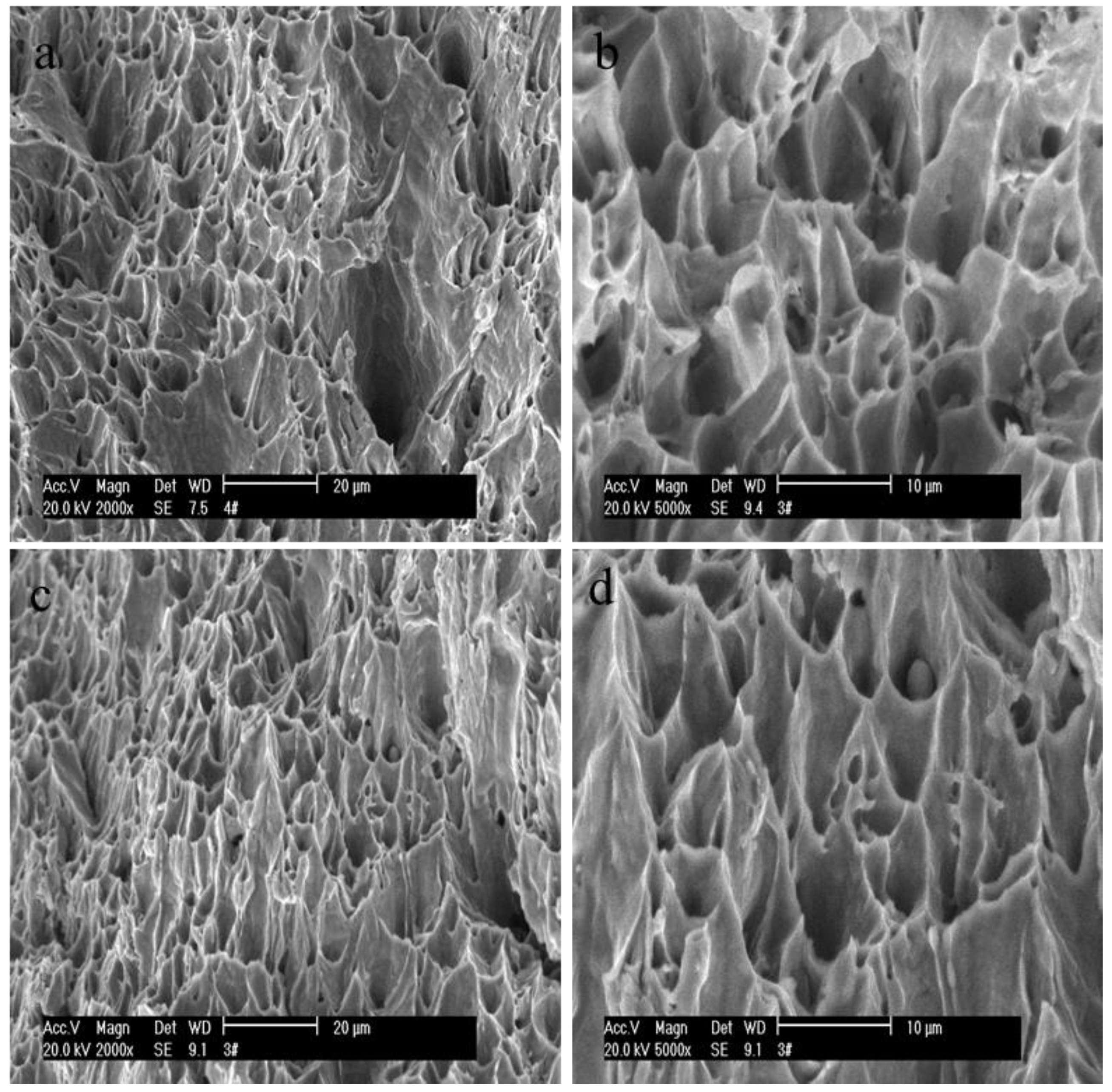
Microscopic observation of the material fracture surfaces with an SEM revealed the presence of numerous dimples. Among them, only one dimple contained an inclusion, which indicated a typical dimple fracture pattern.
(2).
Plastic deformation of the metal resulted in an oversaturation of vacancies, leading to the nucleation of voids at vacancy agglomeration sites. After void nucleation, under high stress triaxiality, the voids continued to grow without material flow to compensate for the pore defects, causing adjacent pores to coalesce and form microcracks. Subsequent crack propagation eventually led to the fracture of the plastic metal.
(3).
Considering the nucleation, growth, and coalescence effects of voids during the plastic deformation of metals, the damage parameters were derived using the R-T model. By combining them with the continuum damage theory, the plastic potential function, hardening curve, and constitutive model were established. The obtained hardening curve showed a good fit with the experimental data, thus validating the accuracy of the plastic potential function, hardening curve, and constitutive model constructed by considering the volume fraction of voids. This confirmed that they can effectively describe the deformation behavior of the material.

Author Contributions

Experiment, J.L.; data processing, J.Z.; writing—original draft preparation, J.Z.; writing—review and editing, Y.J. and G.Z.; supervision, J.L. All authors have read and agreed to the published version of the manuscript.

Funding

This work was supported by the National Natural Science Foundation of China (grant no. 50974068).

Data Availability Statement

Not applicable.

Acknowledgments

The authors gratefully acknowledge Jianxiong Liu for his help in the experiments and data collection, as well as Youdong Jia and Guolin Zhao for their efforts in format review and editing of the manuscripts.

Conflicts of Interest

The authors declare no conflict of interest.

References

  1. Liu, Q.; Wang, J.H.; Zhao, Z.L.; Pu, J.Q.; Yu, D.C.; Luo, S. Study on characteristics of cracking leakage of large oil storage tanks. Contemp. Chem. Ind. 2015, 44, 570–573+576. [Google Scholar]
  2. Li, R.F.; Lin, J.W.; Yue, B.L.; Zhang, C.Y. Analysis of jar breaking and falling accident in Bohai oilfield. Petrochem. Ind. Technol. 2020, 27, 72–74. [Google Scholar]
  3. Yang, S.G.; Jin, Z.M.; Gao, H.; Wei, C. Analysis of pipeline fracture accident. Saf. Technol. Spec. Equip. 2021, 4, 18–20. [Google Scholar]
  4. Mcclintock, F.A. A criterion for ductile fracture by the growth of holes. J. Appl. Mech. 1968, 35, 363–371. [Google Scholar] [CrossRef]
  5. Argon, A.S.; Im, J.; Safoglu, R. Cavity formation from inclusions in ductile fracture. Met. Trans. A 1975, 6, 825–837. [Google Scholar] [CrossRef]
  6. Landron, C.; Bouaziz, O.; Maire, E.; Adrien, J. Characterization and modeling of void nucleation by interface decohesion in dual phase steels. Scr. Mater. 2010, 63, 973–976. [Google Scholar] [CrossRef]
  7. Beremin, F.M. Cavity formation from inclusions in ductile fracture of A508 steel. Met. Mater. Trans. A 1981, 12, 723–731. [Google Scholar] [CrossRef]
  8. Roy, G.L.; Embury, J.D.; Edwards, G.; Ashby, M.F. A model of ductile fracture based on the nucleation and growth of voids. Acta Met. 1981, 29, 1509–1522. [Google Scholar] [CrossRef]
  9. Ye, J.H.; Fan, Z.P. Ductile fracture behavior of steel under complex stress state based on microscopic mechanism. Eng. Mech. 2021, 38, 38–49. [Google Scholar] [CrossRef]
  10. Zhang, J.C.; Lian, C.W.; Han, F. Study on hardening and failure behavior of the 3rd generation ultra-high strength steel QP1180. J. Mech. Eng. 2022, 58, 117–125. [Google Scholar] [CrossRef]
  11. Gruson, A.L. Continuum theory of ductile rupture by void nucleation and growth: Part I—Yield criteria and flow rules for porous ductile media. J. Eng. Mater. Technol. 1977, 99, 2–15. [Google Scholar] [CrossRef]
  12. Tvergaard, V.; Needleman, A. Analysis of the cup-cone fracture in a round tensile test bar. Acta Met. 1984, 32, 157–169. [Google Scholar] [CrossRef]
  13. Needleman, A.; Tvergaard, V. An analysis of ductile rupture in notched bars. J. Mech. Phys. Solids 1984, 32, 461–490. [Google Scholar] [CrossRef]
  14. Deng, Q.F. Analysis for High Temperature Cracking Behavior of MnS Inclusions Based on GTN Damage Model. Master’s Thesis, Yanshan University, Qinhuangdao, China, 2018. [Google Scholar]
  15. Jiang, W. Study of Ductile Fracture Based on Meso-Damage Mechanisms. Ph.D. Thesis, Northwestern Polytechnical University, Xi’an, China, 2016. [Google Scholar]
  16. Dong, J.P.; Wang, S.L.; Zhou, J.; Yang, B.; Ma, C. The ductile fracture criterion of stainless-steel tubes in the shearing process based on modified GTN model. Eng. Mech. 2021, 38, 239–247. [Google Scholar] [CrossRef]
  17. Maire, E.; Bouaziz, O.; Michiel, M.D.; Verdu, C. Initiation and growth of damage in a dual-phase steel observed by X-ray microtomography. Acta Mater. 2008, 56, 4954–4964. [Google Scholar] [CrossRef]
  18. Wu, Y.J.; Zhuang, X.C.; Zhao, Z. Fracture topography analysis of C45 steel under different stress state. J. Plast. Eng. 2013, 20, 106–110. [Google Scholar] [CrossRef]
  19. Yan, H.D.; Jin, H. Three-dimensional characteristics and morphological evolution of micro/meso pores in G20Mn5N steel castings. Acta Met. Sin. 2019, 55, 341–348. [Google Scholar] [CrossRef]
  20. Huang, X.W.; Zhao, W.; Zhao, J.; Wang, Z. Fracture model of Q235B steel considering the influence of stress triaxiality and lode parameter. J. Basic. Sci. Eng. 2019, 27, 1172–1187. [Google Scholar] [CrossRef]
  21. Othmen, K.B.; Haddar, N.; Jegat, A.; Manach, P.Y.; Elleuch, K. Ductile fracture of AISI 304L stainless steel sheet in stretching. Int. J. Mech. Sci. 2020, 172, 105404. [Google Scholar] [CrossRef]
  22. Tang, B.T.; Wu, F.X.; Guo, N.; Liu, J.Y.; Ge, H.L.; Bruschi, S.; Li, X.S. Numerical modeling of ductile fracture of hot stamped 22MnB5 boron steel parts in three-point bending. Int. J. Mech. Sci. 2020, 188, 105951. [Google Scholar] [CrossRef]
  23. Li, Q.; Zhang, H.M.; Chen, F.; Xu, D.K.; Sui, D.S.; Cui, Z.S. Study on the plastic anisotropy of advanced high strength steel sheet: Experiments and microstructure-based crystal plasticity modeling. Int. J. Mech. Sci. 2020, 176, 105569. [Google Scholar] [CrossRef]
  24. Barnwal, V.K.; Lee, S.Y.; Choi, J.; Kim, J.H.; Frédéric, B. On the fracture characteristics of advanced high strength steels during hydraulic bulge test. Int. J. Mech. Sci. 2021, 190, 106032. [Google Scholar] [CrossRef]
  25. Qian, L.Y.; Ji, W.T.; Wang, X.C.; Sun, C.Y.; Ma, T.Y. Research on fracture mechanism and prediction of high-strength steel sheet under different stress states. J. Mech. Eng. 2020, 56, 72–80. [Google Scholar] [CrossRef]
  26. Marteleur, M.; Leclerc, J.; Colla, M.S.; Nguyen, V.D.; Pardoen, T. Ductile fracture of high strength steels with morphological anisotropy, Part I: Characterization, testing, and void nucleation law. Eng. Fract. Mech. 2021, 244, 107569. [Google Scholar] [CrossRef]
  27. Ding, H.J.; Zou, B.; Wang, X.F.; Liu, J.K.; Li, L. Microstructure, mechanical properties and machinability of 316L stainless steel fabricated by direct energy deposition. Int. J. Mech. Sci. 2022, 243, 108046. [Google Scholar] [CrossRef]
  28. Noell, P.J.; Sabisch, J.E.C.; Medlin, D.L.; Boyce, B.L. Nanoscale conditions for ductile void nucleation in copper: Vacancy condensation and the growth-limited microstructural state. Acta Mater. 2020, 184, 211–224. [Google Scholar] [CrossRef]
  29. Rousselier, G. Finite deformation constitutive relations including ductile fracture damage. In Three Dimensional Constitutive Relations and Ductile Fracture; Nemat-Nasser, S., Ed.; Elsevier: Amsterdam, The Netherlands, 1981; pp. 319–343. [Google Scholar]
  30. Rousselier, G. Ductile fracture models and their potential in local approach of fracture. Nucl. Eng. Des. 1987, 105, 97–111. [Google Scholar] [CrossRef]
  31. Rice, J.R.; Tracey, D.M. On the ductile enlargement of voids in triaxial stress fields. J. Mech. Phys. Solids. 1969, 17, 201–217. [Google Scholar] [CrossRef]
  32. Huang, Y.; Hutchinson, J.W.; Tvergaard, V. Cavitation instabilities in elastic-plastic solids. J. Mech. Phys. Solids. 1991, 39, 223–241. [Google Scholar] [CrossRef]
Figure 1. Dimensional data of the uniaxial tensile specimen.
Metals 13 01566 g001
Figure 2. Nominal stress–strain curve of the material tensile test.
Metals 13 01566 g002
Figure 3. Microfracture morphology with different magnifications; (a,c) the two materials with a fracture magnification of ×2000; (b,d) the two materials with a fracture magnification of ×5000.
Metals 13 01566 g003
Figure 4. Fitting results of the hardening curve.
Metals 13 01566 g004
Table 1. Mass fractions of C and Mn elements in the material samples.
Initial Sample NumberTest NumberMass Fraction w/%Young’s Modulus
E/MPa
Yield Strength
σ 0.2 /MPa
Ultimate Tensile Strength σ b /MPa
CMn
steel No. 1KTM 05-10.090.3680,552161.10267.21
steel No. 2KTM 05-20.180.38100,363200.73287.56
Table 2. Possible grades and mechanical parameters of steel No. 1.
GradeMass Fraction w/%Yield Strength
σ 0.2 /MPa
Ultimate Tensile Strength σ b /MPa
CMn
08F0.05~0.110.25~0.50175295
080.05~0.120.35~0.65195325
10F0.07~0.140.25~0.50185315
100.07~0.140.35~0.65205335
08Al0.05~0.120.25~0.65205375
Table 3. Possible grades and mechanical parameters of steel No. 2.
GradeMass Fraction w/%Yield Strength
σ 0.2 /MPa
Ultimate Tensile Strength σ b /MPa
CMn
15F0.12~0.190.25~0.50205355
150.12~0.190.35~0.65225375
15Al0.12~0.190.35~0.65235415
200.17~0.240.35~0.65245410
Table 4. Fitting parameters of the hardening curve.
Material σ s The Error between Fitting and Experimental Yield StressB/MPam
Steel No. 1162.730.63%241.5750.253
Steel No. 2204.942.1%292.2660.397
Disclaimer/Publisher’s Note: The statements, opinions and data contained in all publications are solely those of the individual author(s) and contributor(s) and not of MDPI and/or the editor(s). MDPI and/or the editor(s) disclaim responsibility for any injury to people or property resulting from any ideas, methods, instructions or products referred to in the content.

