Article

Phase Field Simulations of Microstructures in Porous Ferromagnetic Shape Memory Alloy Ni2MnGa

1
The Higher Educational Key Laboratory for Flexible Manufacturing Equipment Integration of Fujian Province, Xiamen Institute of Technology, Xiamen 361021, China
2
Department of Mechanical Engineering, Xiamen Institute of Technology, Xiamen 361021, China
3
Department of Materials Science and Engineering, Xiamen Institute of Technology, Xiamen 361021, China
4
State Key Laboratory for Advanced Metals and Materials, University of Science and Technology Beijing, Beijing 100083, China
*
Author to whom correspondence should be addressed.
Metals 2023, 13(9), 1572; https://doi.org/10.3390/met13091572
Submission received: 9 August 2023 / Revised: 2 September 2023 / Accepted: 6 September 2023 / Published: 8 September 2023
(This article belongs to the Special Issue Preparation, Properties and Applications of Porous Metal)

Abstract

:
The magnetic domain structures and martensite microstructures of porous Ni2MnGa Heusler alloys with various circle-shaped and ellipse-shaped pores were systematically studied by the phase field method. The magnetization curves and magnetic field-induced strains (MFIS) at the external field were determined. A mesoscopic mechanism was proposed for simulation to reveal the influence of the pores on the microstructures and the MFIS of porous magnetic shape memory alloy. The stress concentration effect and the recovery strain of the porous alloy are studied. The results indicate the MFIS value increases when ellipse-shaped pores elongate along the twin boundary. The effects of porosity and pore size on MFIS for porous Ni-Mn-Ga alloys with randomly distributed pores were also explored. The present study is of guiding significance for understanding the role played by pores on the MFIS and may provide a possible way to adjust the functional properties of ferromagnetic shape memory alloys.

1. Introduction

Ferromagnetic shape memory alloy (FSMA), as a kind of multi-ferroic material, presents a coupling between ferromagnetic and ferroelastic properties [1]. In particular, the Heusler alloy Ni2MnGa exhibits extremely high magnetic field-induced strain (MFIS), more than an order of magnitude larger than conventional magnetostriction materials [1,2,3,4,5,6,7,8,9]. FSMA shows a magneto-structural coupling with a magnetic 90-degree domain wall along twin boundaries and induces a cross-response of strain and applied field [1]. Therefore, martensite variants rearrangement and variant twin boundaries motion occur under the action of the external magnetic field [10]. Moreover, driven by an external magnetic field, FSMA exhibits a faster response (higher frequency bandwidth) than conventional shape memory alloys driven by changes in temperature and stress [8]. FSMA offers prospective novel applications in actuators, sensors, energy harvesting devices, and micro-electromechanical systems (MEMS) [8,11].
In recent years, porous FSMAs and FSMA composites have attracted great interest due to their potential application in biomedical devices, shock-absorbing devices, and lightweight actuators/sensors [12,13,14,15]. Chmielus et al. [16] demonstrate that the MFIS of porous Ni-Mn-Ga alloys can reach 2.0–8.7% by introducing pores smaller than grain size. The pore architectures, especially dual-pore foams, have a strong influence on the microstructures and the MFIS of FSMAs [17]. Wang et al. [18] report that their porous Ni-Mn-Ga alloy has completely different mechanical behaviors and that porous structure promotes shape memory effect and superelasticity of FSMAs. An enhanced elastocaloric effect has been discovered in porous Ni-Fe-Ga FSMA foams, making them a promising material for solid-state refrigeration technology [19].
In terms of modeling, porous material can be simply treated as a composite with metals/alloys as the matrix and pores as the inclusions. However, the macroscopic response of the materials is strongly affected by the fraction, distribution, and shape of pores. Many physical models with boundary conditions are employed to simulate porous shape memory alloys in a mesoscopic view. Panico and Brinson [13] simulated porous shape memory alloys using a commercial finite element code. Ke et al. [14] investigated the influence of pores on the phase transformation in NiTi shape memory alloys through phase-field simulation. Gebbia et al. [1] discussed the hysteresis and MFIS of Ni2MnGa at various temperatures by combining the Ginzburg-Landau model and micromagnetism theory. Multi-phase models using the Eshebly theory and Mori–Tanaka method were also employed to investigate the mechanical behaviors and magneto-mechanical coupling between porous FSMAs and FSMA composites under different conditions [12,20]. The multi-phase-field model, as an effective physical-based computational approach, can simultaneously illustrate the evolution of ferromagnetic domain structure and martensite microstructure. In previous works, it has been widely used in the computer simulation of magnetic and mechanical properties of FSMAs [4,21,22,23,24,25] with magnetoelastic coupling. The model is also able to predict the structures of porous materials [26,27].
The main purpose of this paper is to predict the MFIS of porous Ni-Mn-Ga alloys through phase-field simulation. In this paper, two types of distributions are suggested, single-pore simulation works with periodical boundary conditions can be considered as pores homogeneously distributed in the alloys. In practical materials, pores exhibited a trend to be more randomly distributed in the alloy. First, we will focus on the effects of different pore sizes and pore shapes on the magnetic domain structure and martensite structure, with homogenously distributed pores. The magnetization curves and MFIS associated with the structures of materials will be examined and discussed. We will also investigate the value of MFIS as a function of porosity and the effect of pore distribution. This model can simulate the evolution of both the magnetic domain and twinned martensite in the magnetization process under the external field, which provides a basic understanding of the deformation of porous FSMAs. In addition, the MFIS can be enhanced by tuning and controlling the shape and orientation of pores. These simulation results will be of guiding significance for designing novel porous FSMAs for light-weighted and high-capabilities applications.

2. Simulation Methods

To achieve computational efficiency, our current model is built based on the following assumptions:
(1)
For simplicity, a sharp interface was introduced into the phase field parameter eta, the pore (air) phase and the alloy phase were separated by a sharp interface, and the phase field is non-evolving, and represents a static porous structure.
(2)
The defects, including point defects, dislocations, grain boundaries, and stacking faults are neglected in the current implementation.
(3)
The diffusion of the chemical composition, solute redistribution, and segregation during phase transformation are not considered.
(4)
The environmental temperature is static and homogenously distributed in the material.
To simulate the temporal evolution of the magnetic domain and martensite structure of porous Ni-Mn-Ga alloys, three order parameters were selected. The first one is η(r) used to distinguish the alloy phase from the pore phase. In our current simulation, the order parameter η is static and does not evolve with time. η(r) = 1 and η(r) = 0 respectively indicate that position r is occupied by FSMA and pore phase. The second order parameter is spontaneous magnetization M(r) used to describe the magnetic domain structure of FSMA. The third one is the local distribution of strain ε(r) used to describe martensite twin variants. The total free energy of the material is the sum of the terms representing the energy of alloys (Falloy) and that of pores (Fpore). As the energy contribution of pores is zero, therefore, the total free energy can be written as:
F t o t a l = η r F a l l o y + 1 η r F p o r e = η r F m a g n e t i c + F m a r t e n s i t e + F m a g n e t o e l a s t i c = η r f a n i + f e x c h + f m a g s t a t i c + f z e e m a n + f b u l k + f g r a d + f e l a s t i c + f m a g n e t o e l a s t i c d V
where Fmagnetic, Fmartensite, and Fmagnetoelastic are the contributions of magnetic energy, martensite energy, and magnetoelastic coupling energy, respectively. fani, fexch, fmagstatic, fzeeman, fbulk, fgrad, felastic, and fmagnetoelastic are magnetoanisotropy energy, exchange coupling energy, magnetostatic energy, Zeeman energy, bulk landau energy, gradient energy, elastic energy, and magnetoelastic energy, respectively.
The anisotropy energy is an intrinsic property and is determined by the spin-orbit coupling effect, in cubic systems, this energy can be written as
f a n i = K 1 m 1 2 m 2 2 + m 2 2 m 3 2 + m 3 2 m 1 2 + K 2 m 1 2 m 2 2 m 3 2 ,
where mi = Mi/Ms unit vectors in the local direction of magnetization M, and Ms is the magnetization saturation, K1 and K2 are magnetocrystalline anisotropy constants
The exchange coupling energy tends to keep adjacent magnetizations parallel to each other, which is determined by the spatial variation of the magnetization:
f e x c h = A m 2 ,
where A is exchange coupling stiffness.
Magnetostatic energy, which is also called as demagnetization energy, is the energy of the magnetization in the demagnetization field created by the magnetic body itself, can be written as
f m a g s t a t i c = 1 2 μ 0 M s H d m ,
where μ0 is vacuum permeability, Hd = NM is demagnetization field, and N is demagnetization factor, which depends on the shape of the material.
The Zeeman energy is the potential energy of the magnetization in the external applied field Ha, which is given by
f z e e m a n = μ 0 M s H a m ,
The bulk free energy describing the martensitic transformation is written as
f b u l k = Q 1 e 1 2 + Q 2 e 2 2 + e 3 2 + Q 3 e 3 e 3 2 3 e 2 2 + Q 4 e 2 2 + e 3 2 2 ,
where Q1~Q4 are bulk free energy coefficients, ei is three symmetry-adapted strain according to elasticity theory [28].
The strain gradient energy is introduced through the gradients of the strain order parameter, describing the interface energy always associated with twin boundary
f g r a d = 1 2 g [ ε 11 0 x 2 + ε 11 0 y 2 + ε 11 0 z 2 + ε 22 0 x 2 + ε 22 0 y 2 + ε 22 0 z 2 + ε 33 0 x 2 + ε 33 0 y 2 + ε 33 0 z 2 ]
where g is the coefficient of strain gradient.
The elastic energy of the elastic body is given by
f e l a s = 1 2 i , j , k , l = 1 3 C i j k l ε i j ε i j 0 ε k l ε k l 0
where Cijkl is elastic stiffness constant.
Finally, the magnetoelastic energy, which describes the coupling effect between the local strain tensor and the magnetization, is proportional to strain:
f m a g n e t o e l a s t i c = B ε 11 0 m 1 2 1 3 + ε 22 0 m 2 2 1 3 + ε 33 0 m 3 2 1 3
where B is magnetoelastic coupling coefficient.
In our current simulation, with all of the energy contributions, for modeling domain structures and the dynamic response of the magnetization in an applied field, the Landau-Lifshitz-Gilbert (LLG) equation was adopted.
( 1 + α 2 ) M r , t t = γ 0 M ( r , t ) × H e f f γ 0 α M s M ( r , t ) × M ( r , t ) × H e f f ,
where α is damping constant, γ0 is gyromagnetic ratio and Heff is the local effective magnetic field, which can be expressed as:
H e f f = 1 μ 0 F t o t a l M ( r , t ) .
Equations (10) and (11) are solved by employing the Gauss-Seidle projection method in this work [29].
The temporal and spatial evolution of stress-free strain can be described by the Time-Dependent Ginzburg-Landau (TDGL) equations in phase-field simulations.
ε i i 0 r , t t = L δ F t o t a l δ ε i i 0 ( r , t ) ,
where L is kinetic coefficient, and Equation (12) can be solved by employing the semi-implicit Fourier spectral method [30].
All of the simulation parameters used in this work are listed in Table 1. In the 2D simulation, we assumed that the sample was prepared in the shape of a thin disk or rod to reduce the demagnetization effect. To approximate this case, we utilized the demagnetization factor Nx = Ny = 0.02, and Nz = 0.96 in our simulation. The time step for integration was dt/t0 = 0.01, where t0 = (1 + α2)/(γ0 × Ms).

3. Results and Discussion

To study the effect of pores on the magnetization process and MFIS of Ni-Mn-Ga alloys, we first simulated the domain structure and martensite microstructure with ideal circle-shaped pores of different sizes and investigated their magnetic and magnetoelastic properties associated with microstructure. The pores are assumed to be homogenously distributed in the alloy. Then ellipse-shaped pores with various aspect ratios were introduced into the alloys to further explore the MFIS of the porous alloys with ellipse-shaped pores of different elongated directions. Finally, we examined the effects of porosity and pore distribution on the domain shapes and MFIS. In current phase-field simulations, we employed 128 × 128 discrete grid points, and periodic boundary conditions were applied in the x and y directions. A sharp interface was introduced for the order parameter η. Two types of elastic boundary conditions were employed in this work, to generate the initial martensite variant structure, a clamped elastic boundary condition was used, i.e., the system is not allowed to deform. With the application of the external magnetic field, the stress-free boundary condition is employed, which means that the system is unconstrained with respect to the macroscopic deformation, and the local strain ε(r) is obtained by minimizing the total elastic energy. The magnetic insulation boundary condition was assumed along the pore surface, which means that the magnetic field is zero in the normal direction of the boundary. The grid spacing was ~18 nm. Therefore, the size of the simulation system was around 2.5 μm × 2.5 μm.
The phase field simulated domain structure and martensite structure of porous Ni-Mn-Ga alloy with various pore sizes are presented in Figure 1a–f. In terms of dense alloys with a small pore (~0.3 μm), domain structures and martensite microstructure are slightly influenced due to limited changes in magnetic and elastic energy. The pore lies on a 180-degree domain wall inside a single martensite variant without changing the martensite variant structure. With the increase in the pore size, an anti-vortex structure was observed around the pore, and new small variants nucleated with their shapes dictated by energy minimization criteria. Interestingly, with the further increase in pore size, the martensite variant pattern tends to rearrange itself and the staircase-like domain structure gradually disappears.
As the physical properties of FSMAs are associated with their microstructure, it is expected that the MFIS can be significantly influenced by pore architecture. Figure 2a,b illustrates the magnetization curves and MFIS curves of porous Ni-Mn-Ga alloy with different pore sizes. The applied field was applied from zero to 300 kA/m with a step of 12 kA/m in the x direction. For dense FSMAs, the magnetization process can be divided into three stages:
(i)
180-degree domain wall motion occurred, magnetization climbed quickly, but the martensite structure did not change, and there was no MFIS.
(ii)
The 90-degree domain wall began to move with martensite twin boundaries motion, attributed to the effect of the magnetoelastic coupling and material microstructure. The magnetization increased at a lower rate, but MFIS increased rapidly.
(iii)
The magnetization was fully saturated, and the martensite turned to a single-variant structure. The maximal MFIS was obtained by variant reorientation.
The saturation magnetization decreases with the increased degree of porosity in the alloy. The MFIS for alloys with circle-shaped pores decreased from 2.96% at a porosity of 1.2% to 0.036% when the porosity was increased to 44.2%. When the pore size was small, the strain-field curves slightly shifted to the left with the increase of pore size. A significantly reduced MFIS can be seen in the simulation with large-sized pores, which could be explained by the rearrangement of the microstructures of domains and variants. As the volume fraction of 90-degree domain walls decreased, the decoupling between the domain structure and martensite variant structure was observed. Therefore, the magnetization process mainly involved 180-degree domain wall motion and magnetization rotation, indicating that the twin boundary motion could not be driven by the external magnetic field, resulting in a decline in MFIS and loss of performance.
It should be noted that FSMA applications are also limited by the reversible strains. The MFIS can be permanent (magnetoplasticity) or reversible (magnetoelasticity) upon removal of the magnetic field. Based on our previous study, the reversible MFIS is mainly contributed by the magnetoelastic coupling effect induced by the internal stress and the variant boundary movement caused by the defect strain fields. In this simulation work, point defects, grain boundaries, and the training process are not considered. Therefore, near-zero reversible MFIS is observed in porous NiMnGa alloys.
In practical materials, homogenously distributed circle-shaped pores are too ideal and the magnetic/mechanical properties of the simulated structure are not what happens in reality. Here we employed one alternative way, which is to perform simulations with equivalent ellipse-shaped pores due to their capability to be located with various aspect ratios and angles. The domain structure and martensite variants with ellipse-shaped pores are shown in Figure 3. The semi-minor axis of the ellipse-shaped pore was fixed to be 0.3 μm. The pore was elongated in the y direction with an aspect ratio varying from 1:2 to 1:6. The magnetization curves and MFIS curves in the magnetization process are given in Figure 4. The magnetic field was applied along the x direction and similar results were obtained by applying the field in the y direction. Interestingly, a pair of central-symmetrical flux-closed structures appeared in the domain structure, which also distorted the martensite variant boundary near the pore surface. In areas near distorted variant boundaries, magnetization rotation played a major role in the magnetization process, which did not contribute to the twin boundary movement. Since reorientation of the twin variant requires the motion of the twin boundary, which was strongly impeded by the ellipse-shaped pores, the measured MFIS was smaller than the circle-shaped pores at the same porosity level.
To reduce the influence of the pores on the twin boundary motion and improve the MFIS of porous alloys, it was efficient to rotate ellipse pores to make its elongated axis along the direction of the twin boundary. As shown in Figure 5, the elongated axis of the ellipse-shaped pores was rotated to the [110] direction, indicating that the pore architecture had a minor influence on the domain structure and martensite structure. The magnetization curves and MFIS curves slightly changed with the increase in the ellipse-shaped pore size (Figure 6). Complete three-stage magnetization processes were observed in all simulations, and the movement of the twin boundaries was not impeded by the ellipse-shaped pores. The MFIS associated with the twin boundary motion was slightly reduced with increasing porosity.
Figure 7 compares the MFIS for alloys with ellipse-shaped pores aligned in the [010] and [110] directions. For the pores aligned along the [010] direction, the MFIS of the porous alloy was −2.72% at the pore aspect ratio of 1:2, and decreased to −0.78% at the aspect ratio of 1:6. In contrast, after rotating the elongated axis of ellipse pores to the twin boundaries, in the [110] direction, the porous alloy exhibited a small change in MFIS from −2.81% to −2.55% with the increase in aspect ratio. As shown in Figure 7, for a sample with a pore aspect ratio of 1:6, the enhancement of MFIS reached its maximum value up to 227%.
For low porosity alloys, pores can be considered as a kind of defect in metal casting during the solidification process, which can be spherical or elongated shapes. Defects such as pores are analog to micro-cracks, which would lead to a stress concentration from the viewpoint of fatigue. To illustrate the stress concentration effect of the pores, the distribution of local stress σ11 for circle-/ellipse- shaped porous NiMnGa alloy is illustrated in Figure 8a–c. The stress concentration point often stays at the location of twin boundaries or causes a twist of twin boundaries, which can significantly lower the elastic energy at the stress concentration point. Loading tensile stress of 10 MPa was applied along the y direction to the model and the stress distribution is shown in Figure 8d–f. A single variant structure is received in the simulation and a significant concentration point is demonstrated more clearly in the red box of Figure 8.
The effect of reactive stresses in shape memory alloys can be used for applications in various fields [38,39]. In experiments, the sample was initially constrained by slight compression, during the heating process, reactive stresses were developed accompanied by complex elastic and plastic deformations [39]. In our current model, it is difficult to predict the exact value of reactive stress as the grain boundaries and other defects for plastic deformation are neglected. Instead, the recovery strain of the heating process was examined for the porous shape memory alloys. As shown in Figure 9a, porous materials were initially deformed to a single variant structure with a tensile stress of 10 MPa, then heated to above the martensitic transformation point. The porosity dependence of recovery strain was plotted in shown in Figure 9b. The simulation results show that with increasing porosity the recovery strain decreases. Porous alloy initially exhibits a high recovery strain of 3.76% at a porosity of 1.2%, decreasing steadily with porosity to a value of 0.004% for 44.1% porosity.
To investigate the influence of porosity and pore distribution on the MFIS of Ni-Mn-Ga alloy, we performed a larger picture with the simulation size of 10 μm × 10 μm (512 × 512 grids), the circle-shaped pores were randomly distributed with various pore sizes and porosity levels. For high porosity alloys, the randomly distributed circle-shaped pores are overlapped to simulate the complex geometry of the pores phase. Figure 10a–c shows the domain structures and martensite microstructures of porous FSMAs with pore sizes of 1.2 μm, 1.8 μm, and 2.4 μm, respectively. The pores were randomly distributed and controlled at a similar porosity level from 17% to 55% under periodical boundary conditions. At the microscopic scale, the inhomogeneous stress field introduced by pores resulted in nucleation and growth of new twin variants with needle/lamellae shapes, which was consistent with the twining transformation theory in Refs. [8,40]. The magnetic domain structure was also rearranged to reduce the magnetostatic energy. Simulation results showed that the volume fraction of these lamellae-shaped martensite variants was in direct proportion to the porosity level. Figure 11 compares the magnetostrain of porous Ni-Mn-Ga alloy in different porosity. The MFIS was significantly reduced at a high porosity level and reached its minimum at the pore size of 1.8 μm. Increasing the pore size first leads to a decrease in the MFIS, but a higher value of MFIS was observed with a pore size of 2.4 μm. The reason for this effect may result from the distribution of pore architecture and related structures. The strain distribution near small pores is slightly changed and has a minor effect on the twin boundary motion. On the other hand, needle-like/lamellae generated by the large pores with a small curvature surface contribute to the improvement of MFIS.
All of the maximum MFIS values in this work for homogenously/randomly distributed pores as a function of porosity are summarized in Figure 12a. The filled square/circle/triangle dots represent the MFIS simulated with homogenously distributed pores, and hollow star symbols represent the MFIS for alloys with randomly distributed pores. It can be seen that the MFIS of the alloys with randomly distributed pores is lower than that of the homogenously distributed pores, which means that in the experiment, the MFIS can be improved in the samples with evenly distributed pores. A comparison of the results of the numerical simulation with the experimental measurements for porous NiMnGa alloys is plotted in Figure 12b. The simulated MFIS of the porous alloy at a porosity level of 55% is 0.02%, which is lower than the experimental results. The cause for this low MFIS is the suppression of twin boundary motion by the size of the struts. Large struts and nodes between large pores can enhance the MFIS of porous alloys.

4. Conclusions

This paper investigated the effect of pores with various shapes and sizes on the magnetic properties and magnetostrain of Ni-Mn-Ga alloy by employing the phase field method. The following conclusions are reached:
(1)
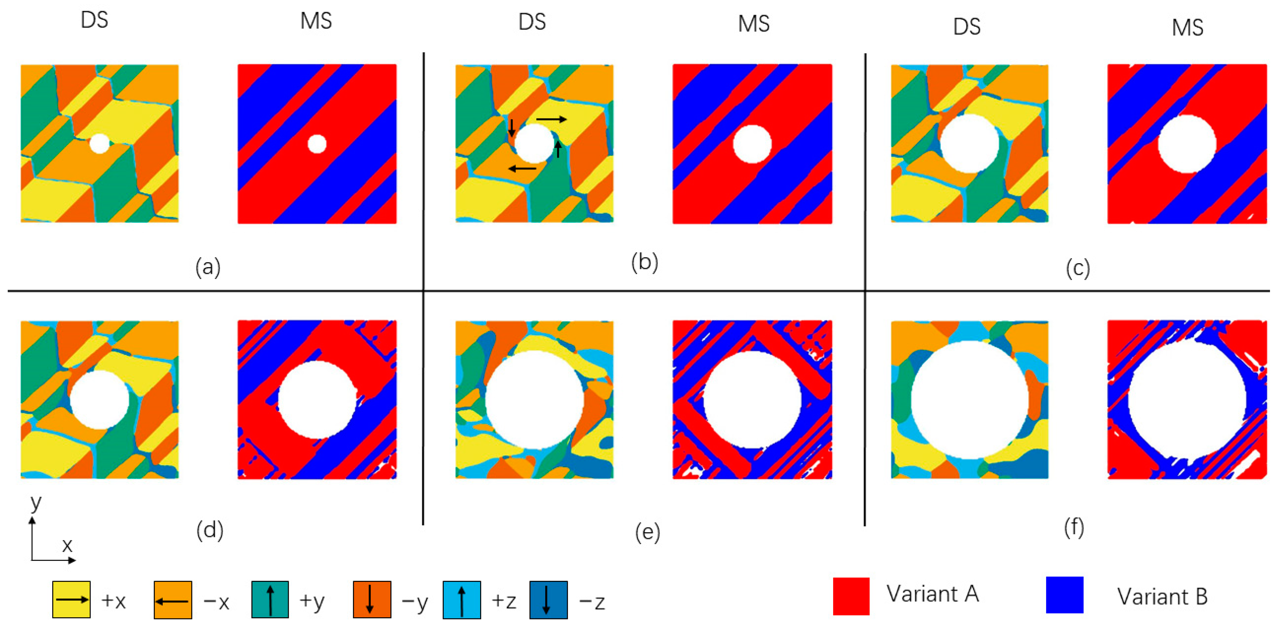
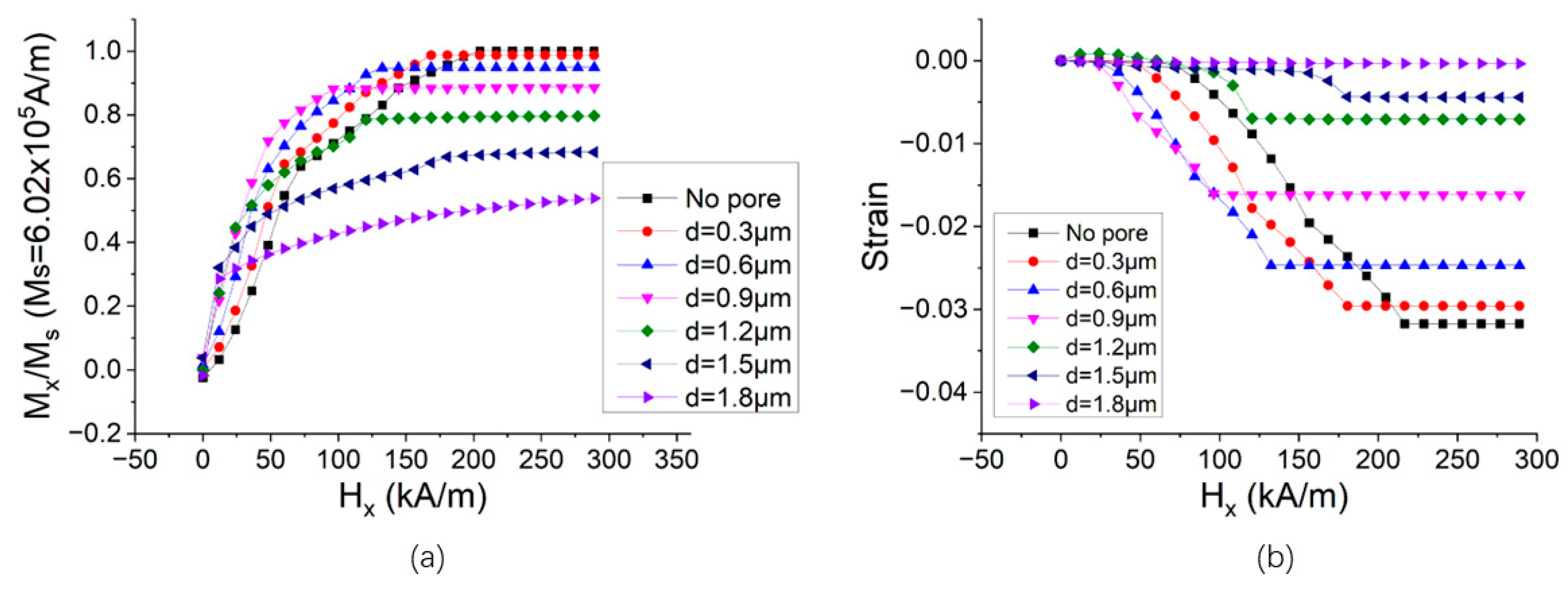
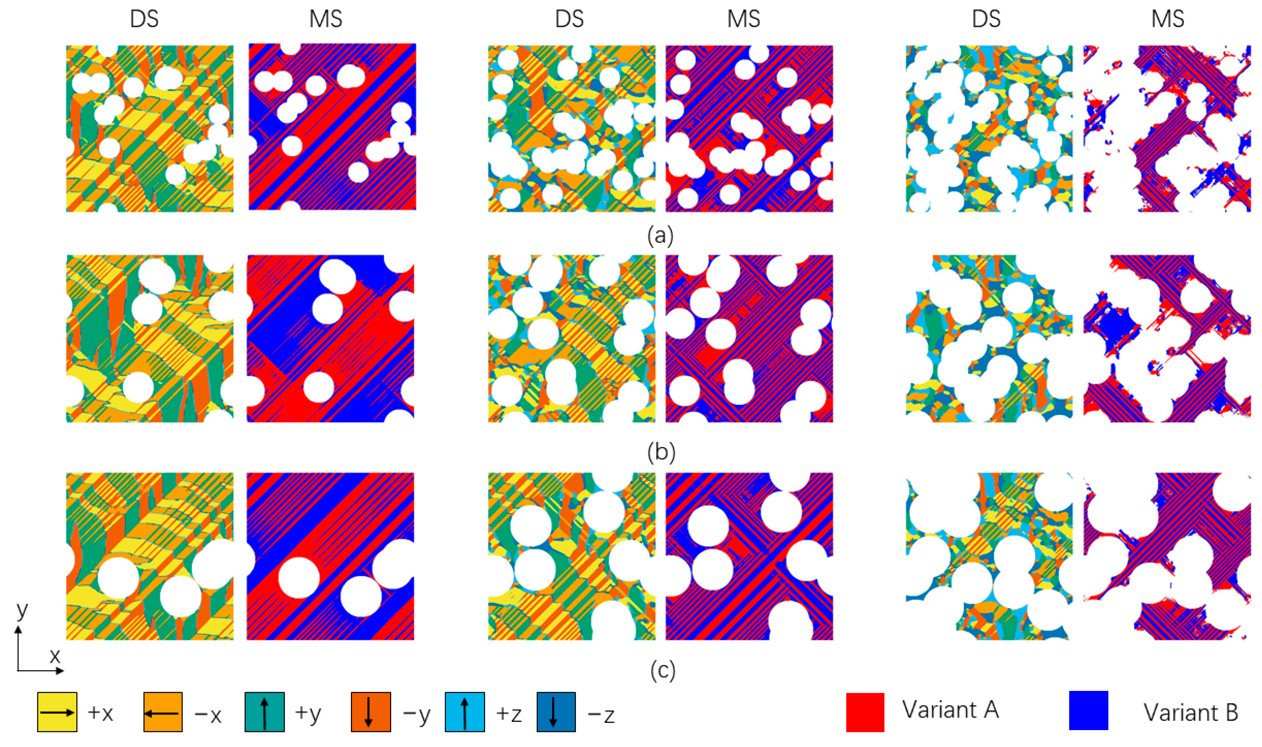
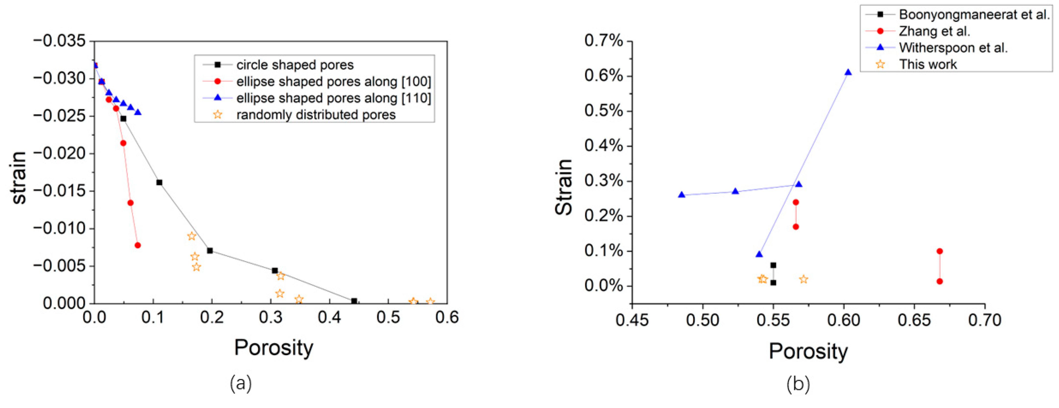
For homogeneously distributed pores, small pores at low porosity have a minor influence on the domain structure and martensite structure. With the increase in pore size and porosity, new martensite variants start to nucleate and grow at the pore surface, which leads to needle-like/lamellae microstructures. The magnetic domain walls are decoupled from the martensite twin boundary and result in a decrease in MFIS. The MFIS for alloys with circle-shaped pores decreased from 2.96% at a porosity of 1.2% to 0.036% when the porosity was increased to 44.2%.
(2)
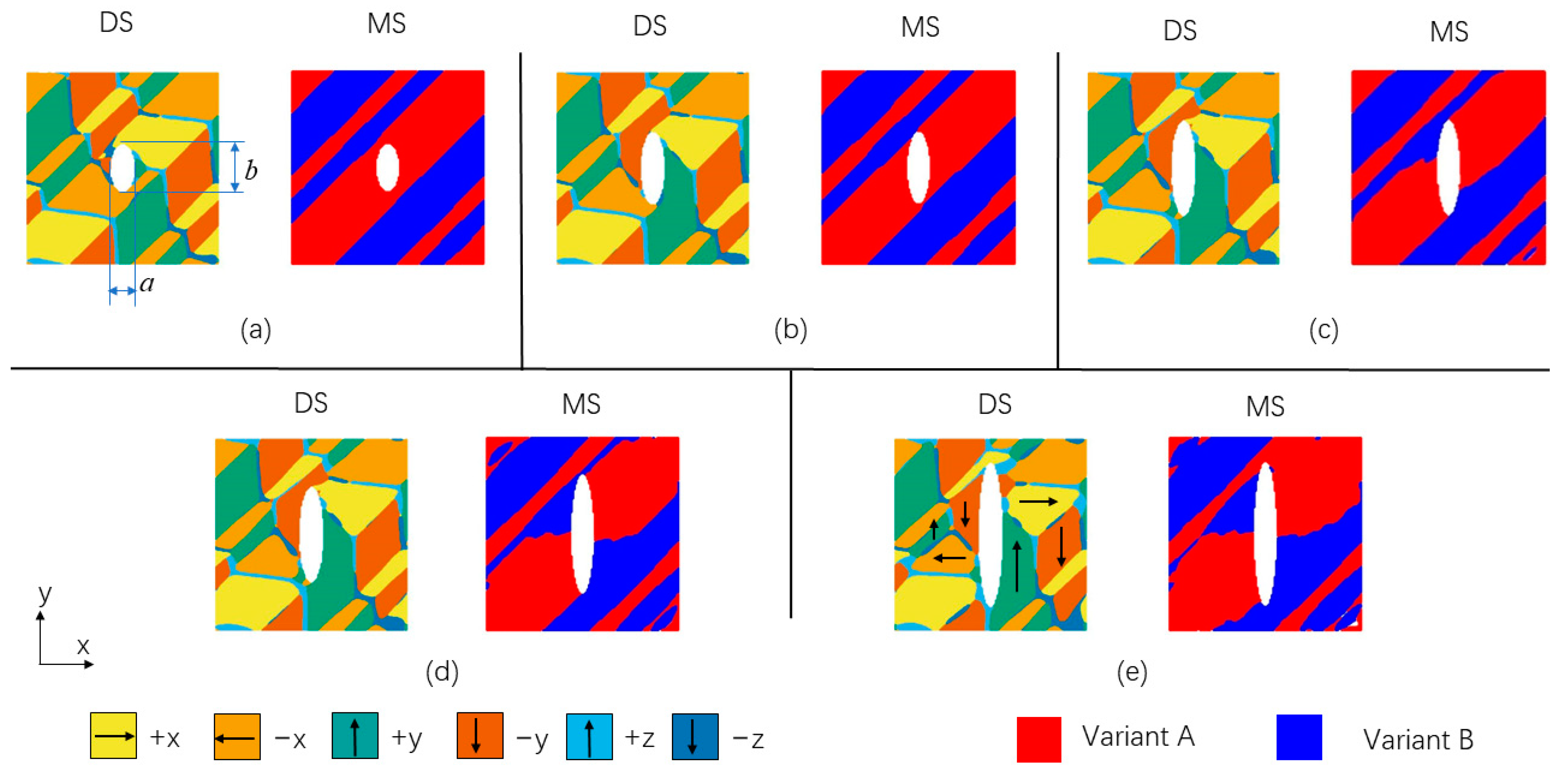
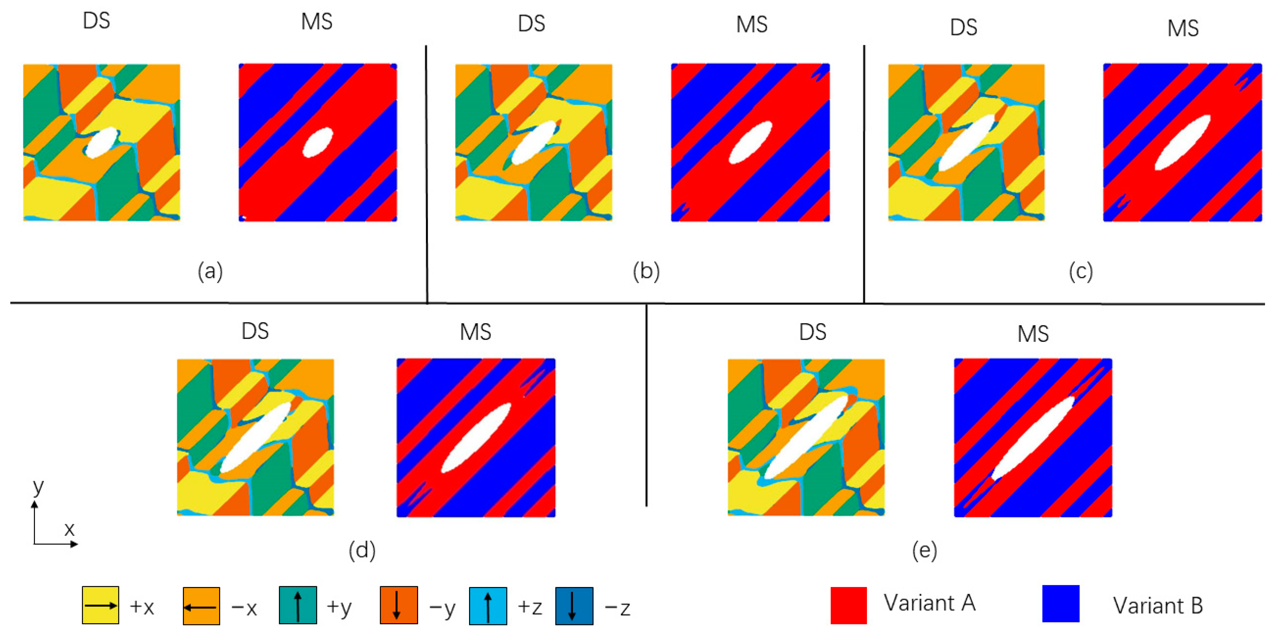
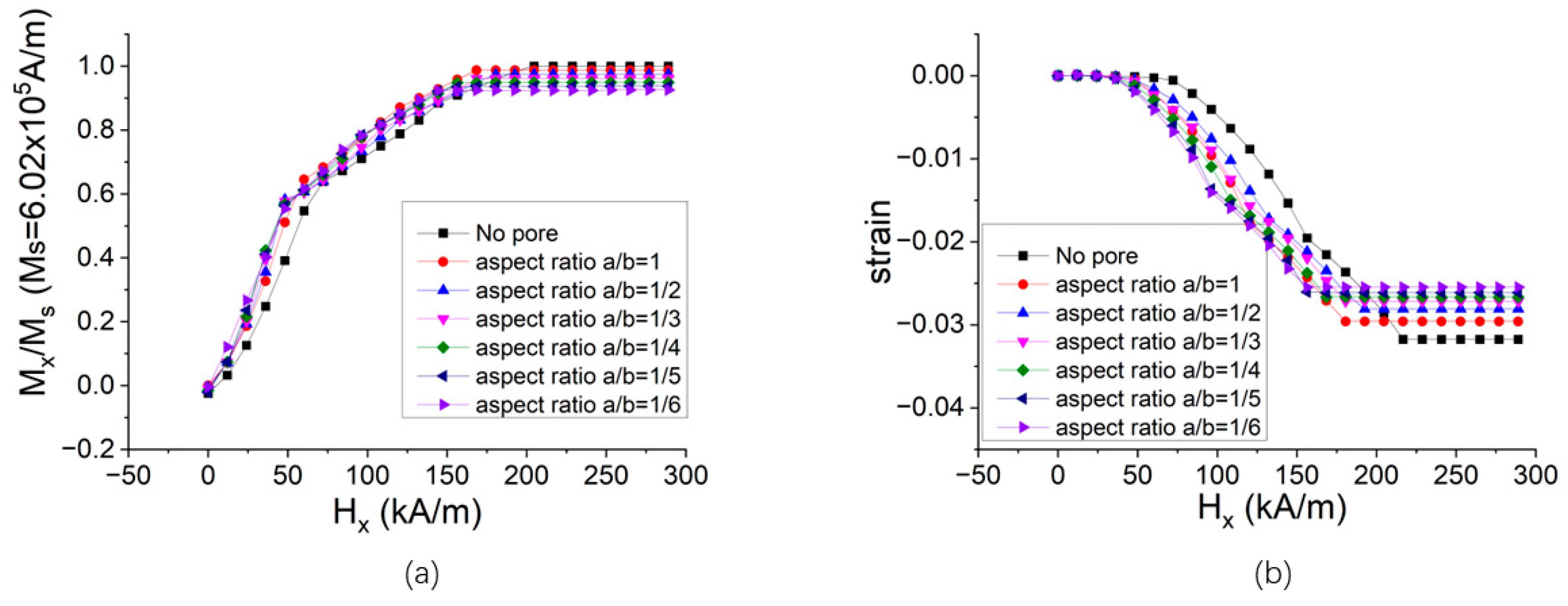
The alignment of ellipse-shaped pores is very important for the MFIS of porous alloys. The elongated direction of ellipse pores oriented along the twin boundaries allows easier movement of twins and enhances the MFIS while maintaining the same porosity. For a sample with a pore aspect ratio of 1:6, the enhancement of MFIS reached a maximum value of up to 227%.
(3)
The pores can be considered as a kind of defect analog to micro-cracks, and lead to a significant stress concentration. The stress concentration point often stays at the location of twin boundaries or causes a twist of twin boundaries to the elastic energy of the system.
(4)
The recovery strain during the heating process was examined for the porous NiMnGa alloys. The recovery strain decreases steadily from 3.76% to 0.004% with increasing porosity from 1.2% to 44.1%.
(5)
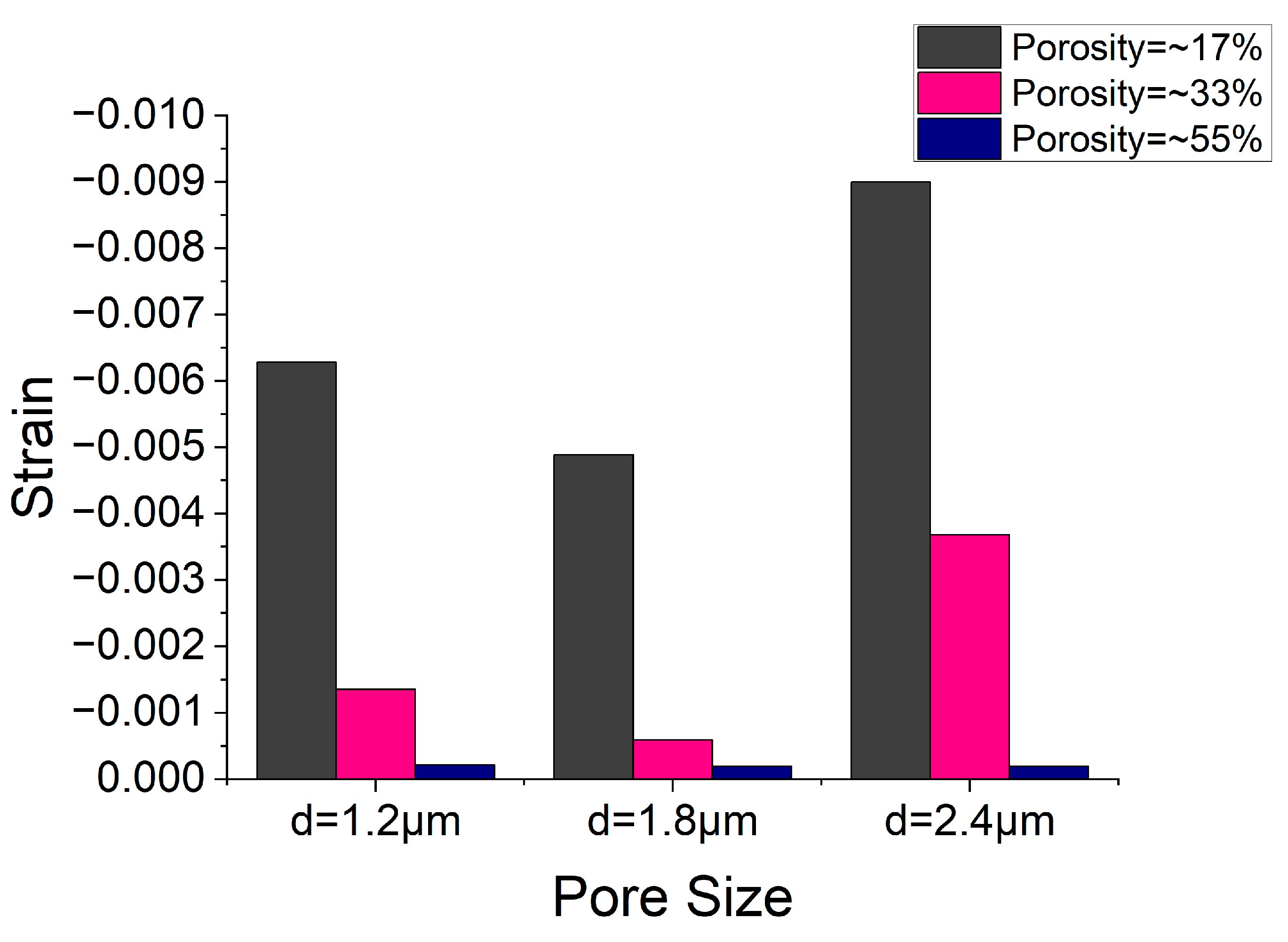
For randomly distributed pore structures, the MFIS drops with the increase in porosity level. The MFIS of the alloys with randomly distributed pores is lower than that of the homogenously distributed pores. The MFIS is also associated with the distribution of pore architecture and related structures. For alloys with the same porosity, smaller or larger pore helps to maintain the optimized value of MFIS.
The present results imply that the properties of MFIS of FSMAs can be tuned and tailored by controlling the shape and size of the pores. It can be expected that this study will be a valuable contribution to establishing reliable magnetostrain properties of porous Ni2MnGa alloys.

Author Contributions

Conceptualization, C.X., Y.L. and P.W.; methodology, P.W.; validation, P.W.; investigation, Y.H. and P.W.; data curation, Y.H.; writing—original draft preparation, C.X. and Y.H.; writing—review and editing, C.X., Y.L. and P.W.; visualization, Y.H. and P.W.; supervision, P.W.; project administration, P.W.; funding acquisition, Y.L. and P.W. All authors have read and agreed to the published version of the manuscript.

Funding

This work was supported by the State Key Lab for Advanced Metals and Materials at the University of Science and Technology Beijing (No. 2021-ZD02), and the Cultivating Research Program of Xiamen Institute of Technology (No. KYZX2023001 and KYTD202004).

Data Availability Statement

Not applicable.

Conflicts of Interest

The authors declare no conflict of interest.

References

  1. Gebbia, J.F.; Castán, T.; Lloveras, P.; Porta, M.; Saxena, A.; Planes, A. Multiferroic and Related Hysteretic Behavior in Ferromagnetic Shape Memory Alloys. Phys. Status Solidi (b) 2017, 255, 1700327. [Google Scholar] [CrossRef]
  2. Zhang, X.; Qian, M. Ferromagnetic Shape Memory Alloys: Foams and Microwires. In Shape Memory Alloys—Fundamentals and Applications; IntechOpen: London, UK, 2017. [Google Scholar]
  3. Chernenko, V.A.; Besseghini, S. Ferromagnetic shape memory alloys: Scientific and applied aspects. Sens. Actuators A Phys. 2008, 142, 542–548. [Google Scholar] [CrossRef]
  4. Koyama, T. Phase-field modeling of microstructure evolutions in magnetic materials. Sci. Technol. Adv. Mater. 2008, 9, 013006. [Google Scholar] [CrossRef]
  5. Liu, G.D.; Liu, Z.H.; Dai, X.F.; Yu, S.Y.; Chen, J.L.; Wu, G.H. Investigation on ferromagnetic shape memory alloys. Sci. Technol. Adv. Mater. 2005, 6, 772–777. [Google Scholar] [CrossRef]
  6. Pons, J.; Cesari, E.; Seguí, C.; Masdeu, F.; Santamarta, R. Ferromagnetic shape memory alloys: Alternatives to Ni–Mn–Ga. Mater. Sci. Eng. A 2008, 481–482, 57–65. [Google Scholar] [CrossRef]
  7. Yu, G.-H.; Xu, Y.-L.; Liu, Z.-H.; Qiu, H.-M.; Zhu, Z.-Y.; Huang, X.-P.; Pan, L.-Q. Recent progress in Heusler-type magnetic shape memory alloys. Rare Met. 2015, 34, 527–539. [Google Scholar] [CrossRef]
  8. Faran, E.; Shilo, D. Ferromagnetic Shape Memory Alloys—Challenges, Applications, and Experimental Characterization. Exp. Tech. 2016, 40, 1005–1031. [Google Scholar] [CrossRef]
  9. Pushin, V.; Korolyov, A.; Kuranova, N.; Marchenkova, E.; Ustyugov, Y. New Metastable Baro- and Deformation-Induced Phases in Ferromagnetic Shape Memory Ni2MnGa-Based Alloys. Materials 2022, 15, 2277. [Google Scholar] [CrossRef]
  10. Huang, L.; Cong, D.; Wang, M.; Wang, Y. Coexisting Multiple Martensites in Ni57−xMn21+xGa22 Ferromagnetic Shape Memory Alloys: Crystal Structure and Phase Transition. Metals 2021, 11, 1534. [Google Scholar] [CrossRef]
  11. Chiu, W.-T.; Okuno, M.; Tahara, M.; Inamura, T.; Hosoda, H. Investigations of the Crystallographic Orientation on the Martensite Variant Reorientation of the Single-Crystal Ni-Mn-Ga Cube and Its Composites for Actuator Applications. Actuators 2023, 12, 211. [Google Scholar] [CrossRef]
  12. Xue, L.; Mu, H.; Sun, Y. Micromechanical model for the ferromagnetic shape memory alloy-epoxy resin composite considering variant reorientation and magneto-mechanical coupling. J. Mech. Behav. Biomed. Mater. 2021, 117, 104396. [Google Scholar] [CrossRef]
  13. Panico, M.; Brinson, L.C. Computational modeling of porous shape memory alloys. Int. J. Solids Struct. 2008, 45, 5613–5626. [Google Scholar] [CrossRef]
  14. Ke, C.; Cao, S.; Ma, X.; Huang, P.; Zhang, X. Phase field simulation of effects of pores on b2–r phase transformation in niti shape memory alloy. Acta Metall. Sin. 2013, 49, 115. [Google Scholar] [CrossRef]
  15. Dunand, D.C.; Mullner, P. Size effects on magnetic actuation in Ni-Mn-Ga shape-memory alloys. Adv. Mater. 2011, 23, 216–232. [Google Scholar] [CrossRef] [PubMed]
  16. Chmielus, M.; Zhang, X.X.; Witherspoon, C.; Dunand, D.C.; Mullner, P. Giant magnetic-field-induced strains in polycrystalline Ni-Mn-Ga foams. Nat. Mater. 2009, 8, 863–866. [Google Scholar] [CrossRef]
  17. Zhang, X.X.; Witherspoon, C.; Müllner, P.; Dunand, D.C. Effect of pore architecture on magnetic-field-induced strain in polycrystalline Ni–Mn–Ga. Acta Mater. 2011, 59, 2229–2239. [Google Scholar] [CrossRef]
  18. Wang, K.; Hou, R.; Xuan, J.; Li, X.; Zhu, J. Shape memory effect and superelasticity of Ni50Mn30Ga20 porous alloy prepared by imitation casting method. Intermetallics 2022, 149, 107668. [Google Scholar] [CrossRef]
  19. Imran, M.; Zhang, X. Ferromagnetic shape memory Ni-Fe-Ga alloy foams for elastocaloric cooling. J. Phys. D Appl. Phys. 2020, 53, 245503. [Google Scholar] [CrossRef]
  20. Song, W.; Tang, X.; Liu, B. A micromechanical constitutive model for porous ferromagnetic shape memory alloys under magneto-mechanical coupling. J. Mater. Res. 2023, 38, 2349–2358. [Google Scholar] [CrossRef]
  21. Wu, P.; Liang, Y. Enhanced Reversible Magnetic-Field-Induced Strain in Ni-Mn-Ga Alloy. Metals 2021, 11, 2017. [Google Scholar] [CrossRef]
  22. Jin, Y.M. Effects of twin boundary mobility on domain microstructure evolution in magnetic shape memory alloys: Phase field simulation. Appl. Phys. Lett. 2009, 94, 3081011. [Google Scholar] [CrossRef]
  23. Peng, Q.; Huang, J.; Chen, M.; Sun, Q. Phase-field simulation of magnetic hysteresis and mechanically induced remanent magnetization rotation in Ni-Mn-Ga ferromagnetic shape memory alloy. Scr. Mater. 2017, 127, 49–53. [Google Scholar] [CrossRef]
  24. Wu, H.-H.; Ke, Y.; Zhu, J.; Wu, Z.; Wang, X.-L. Effects of magnetic frequency and the coupled magnetic-mechanical loading on a ferromagnetic shape memory alloy. J. Phys. D Appl. Phys. 2021, 54, 155301. [Google Scholar] [CrossRef]
  25. Xie, X. Phase field-finite element analysis of magnetic-induced deformation in ferromagnetic shape memory alloy. Comput. Mater. Sci. 2022, 210, 111454. [Google Scholar] [CrossRef]
  26. Xie, C.; Zhao, H.; Du, L.; Du, H.; Wu, P. Enhanced ferroelectricity for nanoporous barium titanate: A phase-field prediction. Philos. Mag. Lett. 2021, 101, 341–352. [Google Scholar] [CrossRef]
  27. Ansari, T.Q.; Huang, H.; Shi, S.-Q. Phase field modeling for the morphological and microstructural evolution of metallic materials under environmental attack. Npj Comput. Mater. 2021, 7, 143. [Google Scholar] [CrossRef]
  28. Lookman, T.; Shenoy, S.R.; Rasmussen, K.Ø.; Saxena, A.; Bishop, A.R. Ferroelastic dynamics and strain compatibility. Phys. Rev. B 2003, 67, 024114. [Google Scholar] [CrossRef]
  29. Zhang, J.X.; Chen, L.Q. Phase-field microelasticity theory and micromagnetic simulations of domain structures in giant magnetostrictive materials. Acta Mater. 2005, 53, 2845–2855. [Google Scholar] [CrossRef]
  30. Chen, L.Q.; Shen, J. Applications of semi-implicit Fourier-spectral method to phase field equations. Comput. Phys. Commun. 1998, 108, 147–158. [Google Scholar] [CrossRef]
  31. Zhang, J.X.; Chen, L.Q. Phase-field model for ferromagnetic shape-memory alloys. Philos. Mag. Lett. 2005, 85, 533–541. [Google Scholar] [CrossRef]
  32. Tickle, R.; James, R.D. Magnetic and magnetomechanical properties of Ni2MnGa. J. Magn. Magn. Mater. 1999, 195, 627–638. [Google Scholar] [CrossRef]
  33. Paul, D.I.; Marquiss, J.; Quattrochi, D. Theory of magnetization: Twin boundary interaction in ferromagnetic shape memory alloys. J. Appl. Phys. 2003, 93, 4561–4565. [Google Scholar] [CrossRef]
  34. Wang, C.; Wang, H.; Huang, T.; Xue, X.; Qiu, F.; Jiang, Q. Generalized-stacking-fault energy and twin-boundary energy of hexagonal close-packed Au: A first-principles calculation. Sci. Rep. 2015, 5, srep10213. [Google Scholar] [CrossRef]
  35. Dai, L.; Cullen, J.; Cui, J.; Wuttig, M.R. Elasticity Study in Ferromagnetic Shape Memory Alloys. MRS Proc. 2003, 785, 221–2210. [Google Scholar] [CrossRef]
  36. Glavatska, N.; Mogilniy, G.; Glavatsky, I.; Danilkin, S.; Hohlwein, D.; Beskrovnij, A.; Lindroos, V.K. Temperature dependence of martensite structure and its effect on magnetic field induced strain in Ni2MnGa magnetic shape memory alloys. J. Phys. IV 2003, 112, 963–967. [Google Scholar] [CrossRef]
  37. Wong, B. Color blindness. Nat. Methods 2011, 8, 441. [Google Scholar] [CrossRef]
  38. Averkin, A.I.; Krymov, V.M.; Guzilova, L.I.; Timashov, R.B.; Soldatov, A.V.; Nikolaev, V.I. Reactive Stresses in Ni49Fe18Ga27Co6 Shape-Memory-Alloy Single Crystals. Tech. Phys. Lett. 2018, 44, 181–183. [Google Scholar] [CrossRef]
  39. Belyakov, V.N. The effect of generating reactive stresses in the spring elements of titanium nickelide. IOP Conf. Ser. Mater. Sci. Eng. 2019, 656, 012009. [Google Scholar] [CrossRef]
  40. Conti, S.; Lenz, M.; Rumpf, M.; Verhülsdonk, J.; Zwicknagl, B. Geometry of Needle-Like Microstructures in Shape-Memory Alloys. Shape Mem. Superelasticity 2023. [Google Scholar] [CrossRef]
  41. Boonyongmaneerat, Y.; Chmielus, M.; Dunand, D.C.; Müllner, P. Increasing Magnetoplasticity in Polycrystalline Ni-Mn-Ga by Reducing Internal Constraints through Porosity. Phys. Rev. Lett. 2007, 99, 247201. [Google Scholar] [CrossRef]
  42. Witherspoon, C.; Zheng, P.; Chmielus, M.; Dunand, D.C.; Müllner, P. Effect of porosity on the magneto-mechanical behavior of polycrystalline magnetic shape-memory Ni–Mn–Ga foams. Acta Mater. 2015, 92, 64–71. [Google Scholar] [CrossRef]
Figure 1. Ferromagnetic Domain Structure (DS) and Martensite Structure (MS) with a circle-shaped pore of various diameters of (a) 0.3 μm, (b) 0.6 μm, (c) 0.9 μm, (d) 1.2 μm, (e) 1.5 μm, and (f) 1.8 μm. The magnetic domains colored yellow, orange, vermillion, bluish-green, sky blue, and blue represent magnetization vectors towards the +x, −x, +y, −y, +z, and −z, directions. Colors are optimized for color-blind individuals (data from ref. [37]).
Metals 13 01572 g001
Figure 2. Simulated (a) magnetization curves and (b) MFIS curves of Ni2MnGa alloy with circle-shaped pores.
Metals 13 01572 g002
Figure 3. Ferromagnetic Domain Structure (DS) and Martensite Structure (MS) with the ellipse-shaped pore of various aspect ratios (a) a/b = 1/2, (b) a/b = 1/3, (c) a/b = 1/4, (d) a/b = 1/5, (e) a/b = 1/6. The elongated axis of the ellipse-shaped pores was long [010] direction.
Metals 13 01572 g003
Figure 4. Simulated (a) magnetization curves and (b) MFIS curves of Ni2MnGa alloy with ellipse-shaped pores elongated along the y direction.
Metals 13 01572 g004
Figure 5. Ferromagnetic Domain Structure (DS) and Martensite Structure (MS) with the ellipse-shaped pore of various aspect ratios (a) a/b = 1/2, (b) a/b = 1/3, (c) a/b = 1/4, (d) a/b = 1/5, (e) a/b = 1/6. The elongated axis of the ellipse-shaped pores was rotated toward the [110] direction.
Metals 13 01572 g005
Figure 6. Simulated (a) magnetization curves and (b) MFIS curves of Ni2MnGa alloy with ellipse-shaped pores with the elongated direction along the direction of the twin boundary.
Metals 13 01572 g006
Figure 7. Quantitative comparison between MFIS between ellipse-shaped pores aligned along [010] direction and [110] direction.
Metals 13 01572 g007
Figure 8. The distribution of local stress σ11 for porous NiMnGa alloy with (a) circle-shaped pores, (b) ellipse-shaped pores along y direction, and (c) ellipse-shaped pores along [110] direction. (df) After a tensile stress of 10 MPa is applied along the y direction, the stress concentration point is demonstrated more clearly in the red box.
Metals 13 01572 g008
Figure 9. (a) Schematic illustration of the evolution of porous martensite variant structure during the deformation and heating process. (b) Porosity dependence of recovery strain.
Metals 13 01572 g009
Figure 10. Simulated magnetic domain structures and martensite microstructures with circle-shaped pores of various diameters of (a) 1.2 μm, (b) 1.8 μm, and (c) 2.4 μm. The pores are randomly distributed and controlled at a certain porosity level: left, ~17%, central, ~33%, and right, ~55%.
Metals 13 01572 g010
Figure 11. Predicted MFIS of porous Ni2MnGa alloys with three different pore sizes, 1.2 μm, 1.8 μm, and 2.4 μm. With the increase in porosity, the MFIS significantly decreased.
Metals 13 01572 g011
Figure 12. (a) Porosity dependence of MFIS for pores with various sizes/shapes simulated in this work. (b) Comparisons of the simulated MFIS with randomly distributed pores and experimental results from Boonyongmaneerat et al. (data from Ref. [41]), Zhang et al. (data from Ref. [17]) and Witherspoon et al. (data from Ref. [42]).
Metals 13 01572 g012
Table 1. The coefficients and parameters used in the simulation (data from Refs. [21,31]).
SymbolDescriptionValue UnitRef.
μ0vacuum permeability4π × 10−7H/m
Msmagnetization saturation6.02 × 105A/m[32]
Aexchange stiffness2 × 10−11J/m[33]
K1anisotropy constant2.7 × 103J/m3[32]
K2anisotropy constant−6.1 × 10³J/m3[32]
Q1bulk energy coefficients2.32 × 1011J/m3[31]
Q2bulk energy coefficients3.78 × 108 × (TTM)/TMJ/m3[31]
Q3bulk energy coefficients0.40 × 1010J/m3[31]
Q4bulk energy coefficients7.50 × 1010J/m3[31]
gstrain gradient coefficient1.0 × 10−8J/m[34]
C11elastic constant1.60 × 1011N/m2[35]
C12elastic constant1.52 × 1011N/m2[35]
C44elastic constant0.43 × 1011N/m2[35]
Bmagnetoelastic coupling coefficient2.00 × 106N/m2[32]
Ttemperature250K
TMmartensite transition temperature300K[36]
Disclaimer/Publisher’s Note: The statements, opinions and data contained in all publications are solely those of the individual author(s) and contributor(s) and not of MDPI and/or the editor(s). MDPI and/or the editor(s) disclaim responsibility for any injury to people or property resulting from any ideas, methods, instructions or products referred to in the content.

