Article

Fabrication of Uniform and Rounded Closed-Cell Aluminum Foams Using Novel Foamable Precursor Particles (FPPs)

Department of Mechanical Engineering, San Diego State University, 5500 Campanile Dr., San Diego, CA 92182, USA
*
Author to whom correspondence should be addressed.
Metals 2024, 14(1), 120; https://doi.org/10.3390/met14010120
Submission received: 17 December 2023 / Revised: 9 January 2024 / Accepted: 15 January 2024 / Published: 19 January 2024

Abstract

:
The powder metallurgy (PM) route for the production of closed-cell metallic foams has recently received a significant amount of attention. One of the major issues is the non-uniform and non-spherical nature of the cells produced, which can negatively affect the mechanical behavior. The current paper uses the PM route to process metallic foams for the first time using novel Al-TiH2 foamable precursor “particles” (FPPs). The effect of FPP content (0–10 wt.%) on the developed foam structure of aluminum and its mechanical properties is investigated. An increase in FPP content results in a decline in product density by forming uniform and near-spherical cells. The main advantage of the FPPs is the localization of the blowing agent TiH2 particle content within Al-TiH2 composite particles (i.e., giving rise to a higher local TiH2 content), which has led to the production of pores with relatively high circularities even at very low overall TiH2 contents. The foams produced displayed energy absorption capacities of 10–25 MJ/m3 at 50% strain, and maximum energy absorption efficiencies ranging from 0.6–0.7 (for 40–60% closed cell content)

1. Introduction

Interest in metallic foams has significantly grown over the past few decades, largely due to their unique physical and mechanical properties [1,2,3,4]. Such properties include a high internal specific surface area (for open-cell foams), a high stiffness-to-weight ratio, a high strength-weight ratio, and an ability to absorb sound and energy [5,6,7,8,9,10,11]. There are two basic types of metallic foams, open-cell foams, where the pores are interconnected throughout the foam structure, and closed-cell foams, where pores are isolated inside the volume of the foam. Aluminum (Al)/Al alloy foams are the most studied metallic foams, both as open-cell foams [12,13] and closed-cell foams [14,15]. The production of closed cell aluminum foams has been limited to two main approaches, the melt route [16] and the powder metallurgy (PM) route [17]; the latter has recently been reviewed by one of the authors [4]. In the PM route, aluminum powders are mixed with a blowing agent powder (i.e., a gas-releasing powder, such as titanium hydride (TiH2) [18]) and compacted to form a highly dense “bulk” foamable precursor [19]. This bulk foamable precursor is then heated to a temperature at or above the melting point of aluminum and, in doing so, hydrogen gas is released from the TiH2 particles into the molten aluminum, resulting in the formation of bubbles, which later solidify as pores upon cooling. One of the main issues regarding TiH2, is the early release of hydrogen at considerably lower temperatures than the melting point of aluminum (660 °C), which leaves less gas for foaming. Although the hydrogen release onset temperature of TiH2 can vary depending on several factors, typically, a temperature around 400 °C is reported; e.g., 420 °C using gravimetry [20] (350 °C was also reported using thermal desorption spectroscopy, which is more sensitive than gravimetry [21]). This places stringent processing requirements both on the TiH2 particles and the foamable precursor. Although many studies have used TiH2 powder in the as-received condition, others have resorted to pre-oxidizing it through a heat treatment cycle in air (e.g., 480 °C for 180 min [22]) to produce an oxide layer at the surface, which acts as a barrier to hydrogen loss; depending on the conditions, this ultimately results in the raising of the gas release onset temperature; for example, by 45–170 °C [23,24] (hence getting it closer to the melting point of aluminum). Others have resorted to coating the TiH2 [25,26] to achieve similar objectives, while a recent study showed that conducting foaming at higher ambient gas pressure, can also result in less gas loss [27]. An additional requirement for the bulk foamable precursor is that its relative density needs to be ~99% of theoretical [28]. At this density, open (interconnected) porosity in the compacted powder-based foamable precursor would have been eliminated [29], leaving only isolated closed pores and hence limiting the escape of gas from the bulk foamable precursor prior to reaching the foaming temperature. Recently, “foamable precursor particles” (FPPs), where TiH2 particles are already embedded and encapsulated in individual microscale and macroscale aluminum powder particles, have been introduced [30,31]. This represents a marked departure from the conventional macro-scale bulk foamable precursors on which the vast majority of research has so far been dependent. The use of FPPs opens the door to several exciting possibilities, including the ability to produce microscale foamed products, to selectively foam materials in specific/strategic locations in a material structure or as self-foaming coatings (cladding). Moreover, FPPs may also lift some of the restrictions mentioned above. For example, the encapsulation of numerous TiH2 particles within the protective fold of an aluminum particle should provide some protection against the early release of TiH2 and avoid the stringent need to compact bulk formable precursors to extremely high densities at room temperature, which is currently not easily achievable for strong alloy powders (for which high temperature compaction processes are typically employed; e.g., as seen in the hot pressing of AlSi6Cu4 [27]). All these could be potentially avoided through the use of FPPs.
So far, research into FPPs has been extremely limited, solely focusing on the foaming characteristics of the individual foamable particles [30,31]. In the present study, FPPs are added in varying amounts to aluminum powder for the first time to produce bulk aluminum foams. A unique feature of bulk foaming precursors based on FPPs is that the TiH2 content is only concentrated within the FPPs giving rise to locally higher TiH2 content than the overall nominal TiH2 content of the bulk foamable precursor, which may have some beneficial outcomes in terms of local pore rounding. The effect of FPP content on the foaming characteristics, compressive stress-strain behavior, energy absorption capacity, energy absorption efficiency, and microhardness of bulk aluminum foams are discussed.

2. Experimental Procedures

Aluminum powder (−325 mesh, Atlantic Equipment Engineers, Upper Saddle River, NJ, USA) (98 wt.%) and TiH2 powder (−325 mesh, Alfa Aesar, Ward Hill, MA, USA) (2 wt.%) were mechanically milled using a SPEX 8000 mill (SPEX Sample Prep, Metuchen, NJ, USA) at 1700 rpm. Both powders were placed together in an A2 steel vial and milled under an argon atmosphere for 1.5 h using a 5:1 ball-to-powder weight ratio. Methanol (1–2 wt.%) was added as a process control agent to prevent excessive aluminum powder cold welding and powder sticking to the walls of the vial. The Al-TiH2 composite FPPs were then mixed (in a rotator mixer at 70 rpm) in varying amounts with the −325 mesh (<45 µm) aluminum powder as presented in Table 1, to produce Al/FPP powders of varying compositions from 0 to 10 wt.% FPP particle content (equivalent to 0 to 0.2 wt.% TiH2 overall nominal TiH2 composition). For each composition, 4 g of Al/FPP powder was compacted in a 19-mm double action compaction die utilizing a compaction press (Black Widow, Germantown, WI, USA) with a 20-ton capacity. An average compaction pressure of 515 MPa was used to produce the green compacts (i.e., foamable precursors) of relative densities equal to or greater than 93% of the theoretical.
Each foamable precursor was then placed in a graphite cylindrical crucible with an inner diameter 20 mm and positioned within the coils of an induction heater (Vevor, Rancho Cucamonga, CA, USA). Here, induction heating was employed by passing 280 A of current through the induction coils to invoke heating rates of the bulk foamable precursors greater than 12.5 °C/s (which is higher than typical heating rates observed in conventional foaming e.g., 1–5 K/s) [32] as an added precaution to minimize hydrogen release from the TiH2 prior to the compact reaching the melting point of aluminum. Note that the gas release onset temperature for TiH2 has been reported to shift to higher temperatures with an increase in heating rate [33]. A hole was drilled in the bottom of the bulk foamable precursor to allow the placement of a K-type thermocouple to monitor the temperature during the foaming process. Initially, the composite FPP-based bulk foamable precursor temperature rapidly increased, then almost plateaued at around 660 °C (the melting point of aluminum), at which point a considerable amount of product expansion was observed. This was then followed by a further increase in temperature, and when the thermocouple read 700 °C, the current supply was switched off. Residual heat in the crucible was found to cause a further increase in temperature to around ~740 °C, then the foamed product was left to cool to room temperature.
Particle size and morphology of the FPPs were characterized using a Hitachi TM3000 field emission scanning electron microscope (FESEM) (Hitachi-HighTech, Schaumburg, IL, USA). Foamed products were cross-sectioned using a Buehler IsoMet 1000 precision saw (Buehler, Lake Bluff, IL, USA) and ground and polished using a Leco Spectrum System 1000 (LECO Corporation, St. Joesph, MI, USA). Porosity in the foam was characterized using optical and stereomicroscopes and the resulting images were processed using ImageJ software (Version 1.53j). The projected area spherical diameter (here called the equivalent diameter) was used to determine the pore sizes from images. Compression testing cuboid samples were prepared from the foamed products and classified into two groups based on their height-to-width (H/W) ratios (Groups A and B had a H/W ratio of 0.4 and 0.7, respectively, as noted in Table 1). The average length and width of each sample was approximately 12 mm. The densities of these samples were measured and reported. Compression testing was carried out using an Instron 3385H universal testing machine (Instron, Norwood, MA, USA) using a crosshead speed of 0.5 mm/min. Keller’s solution was used to etch the aluminum foam cross-sections to investigate the microstructure. To investigate the local mechanical response of the foams, microhardness testing was conducted using loads of 0.5, 0.1, and 0.05 kgf, using a Wilson Instruments hardness tester (Buehler, Lake Bluff, IL, USA). At least 5 indents were made for each investigated composition and load, and an average and standard deviation were reported.

3. Results and Discussion

Figure 1a shows SEM micrographs of the mechanically milled Al-TiH2 FPPs, having an average particle diameter of ~140 µm. It is important to note that at this particle size, it is much less likely for agglomeration to occur, as would have been the case if fine TiH2 powders were simply mixed with aluminum powder. During mechanical milling, the milling balls impact both Al and TiH2 powder, the TiH2 powder fractures and reduces in size (in our case to less than ~2 µm), while the ductile aluminum powder deforms under the impact, work hardens, and fractures then reweld. It is during this Al powder rewelding stage that the TiH2 particles become entrapped in between the rewelding Al particles, and a continuation of this process leads to the homogenous dispersion of TiH2 within aluminum particles; i.e., the formation of composite FPPs. Previously published research by one of the authors describes in more detail the Al-TiH2 mechanical milling process and the distribution of TiH2 within the volume of Al powder [30,31]. Figure 1b is a higher magnification image of a FPP showing dispersed TiH2 (white) in Al powder, and the welding boundaries resulting from the mechanical milling process.
It has previously been reported that the hydrogen release temperature of TiH2 is reduced with a decline in TiH2 particle size [20]. The use of fine individual TiH2 particles may also result in agglomeration and poor distribution within the bulk precursor leading to inhomogeneous foaming and foam cell structures, which is detrimental to the mechanical properties of the final foam [22]. In the FPP approach, although a reduction in gas release onset temperature is expected, the TiH2 particles are not only better dispersed, but are also encapsulated in the Al particles, thus hindering the early escape of hydrogen.
Figure 2 shows the cross-sections of the foamed products, showing an increase in pore content, product expansion, and increased uniformity in pore sphericity with an increase in Al-TiH2 composite FPP content. The distribution and coverage of the pores was also found to improve with an increase in FPP content.
Figure 3 shows the product density and average percent porosity for foams of varying TiH2 content. As expected, with increasing TiH2 content the porosity increases while the product density decreases. Porosities of 50% and 60% were achieved for overall TiH2 contents of 0.1 wt.% and 0.2 wt.%, respectively. As mentioned, FPP-free samples were produced using the same processing/foaming conditions and were found to contain approximately 11% porosity in the foamed product. The source of this porosity is likely due to adsorbed low boiling point species on the aluminum powder surfaces [34] (which has recently been referred to as an intrinsic source of gas [35] separate from that of the blowing agent) and the initial residual porosity in the compacted bulk foamable precursor. This initial residual porosity in the precursor was measured to be no more than 7%.
Papantoniou et al. [36] examined the effect of compaction pressure on the foaming characteristics of Al- 0.6 wt.% TiH2 powder compacts and concluded that a compaction pressures of at least 700 MPa was needed to produce significant foam expansion, resulting in foams with porosity ranging from 40–70%. In the present study, a similar porosity range was achieved at a lower compaction pressure of 515 MPa and a lower overall TiH2 content of 0.06–0.20 wt.%. Hence, it appears that FPPs may also be used to combat the effects of lower bulk foamable precursors and hydrogen escape during precursor heating. However, further investigations are still needed to substantiate this hypothesis.
An analysis of the pore structure reveals similar structures in all processed foams, with large macropores present throughout the products in addition to smaller micropores located in between the macropores. The macropores (>0.1 mm diameter) make up most (~60–90%) of the total pore content, with the remainder being the micropores. This micro-porosity is most likely generated from the small pockets of air that are trapped in the powder compact during the compaction stage, or what has been referred to as satellite pores [37], which have been observed in zinc and to a lesser extent in aluminum foams. Since the bulk precursor density was more than 93%, the residual porosity of <7% largely consisted of closed/isolated [29] pores in which gas can be trapped and expected to expand during foaming. Such a mechanism may have also contributed to the observed porosity for FPP-free Al foamable bulk precursors.
The pore size distributions (frequency plots and cumulative percent finer) of visible pores are shown in Figure 4. For the 3%, 5%, and 10% FPP content foams, approximately 29% of the visible pores are greater than 1 mm in diameter. For the 0% and 1% foams, this number is only 13% and 14%, respectively. This suggests that FPP content increases pore size up to a limit. The average pore diameters of the foamed products were 0.6 mm, 0.7 mm, 0.8 mm, and 0.8 mm, for the 1%, 3%, 5%, 10% composite FPP content foams, respectively. The increase in average pore size is a consequence of increased cell wall rupture events and pore coalescence [22].
The effect of FPPs on pore circularity was also analyzed in the present work. Circularity values range from 0–1, with 1 representing a perfect circle, and higher values generally promoting better mechanical properties. Figure 5 shows the average circularity of pores for each specimen with varying FPP content. In addition, Figure 6 shows pore circularity versus the effective pore diameter. All FPP-based samples show high average circularity values of 0.78 or greater. For pore diameters less than 2 mm, most of the pores have circularities greater than 0.85. However, the average circularity values for the processed foams ranged from 0.79–0.87 under the investigated conditions. Wang et al., using the PM route within the confinement of a stainless steel pipe, reported a decline in circularity with an increase in sample temperature (710 °C–750 °C) [38], and mean circularity values of the pores between 0.734 and 0.835. However, at a sample temperature of 740 °C (which represents our current foaming temperature), circularities of 0.763 and 0.773 were reported. In another study, for AlSi6Cu4 alloy foams (PM route) cooled at different rates following foaming, average circularities of 0.76–0.78 were reported [22]. The FPPs approach seems to favor improved circularities. This is even more pronounced if we consider the work by Youn and Kang [39], who conducted foaming on Al6061 using induction heating (the same heating method used in the present study), they reported that more rounded pores were only attainable at a high TiH2 content (0.7 wt.% and 1.0 wt.), and TiH2 contents below 0.7 wt.% and down to 0.3 wt.% resulted in elongated pores at a foaming temperature of 640 °C. An increase in foaming temperature to 660 °C did result in improved pore roundness, although circularity was not reported, a mean aspect ratio of 1.53 for the pores was instead reported, showing the pores were not ideally circular. Moreover, visual inspection of the reported micrographs clearly shows more rounded pores for our FPP-based foams. A possible reason why the FPP approach can produce more rounded pores, even at such low TiH2 contents (0.2 wt.% and less), is inherent in the approach itself. Unlike the melt route where pores are stabilized by the addition of ceramic particles, in a powder-based route, metal powders inherently contain surface oxides, and hence externally added ceramic powders are not needed. We also noted that the FPPs were produced through the process of mechanical milling, although the milling was conducted in an argon environment, it is impossible to eliminate all the oxygen and hence the presence of oxygen is still expected during milling. As powders are impacted by the balls, the passivating alumina nano surface layers on aluminum powders are broken, thus exposing the virgin metal surface, which then becomes oxidized due to the presence of the residual oxygen, resulting in an increased oxide content. This is in line with recent published results, where mechanical milling has been shown to lead to a local increase in the oxide content of milled aluminum powder [40] and consequently contributes to pore stability. The expected larger mean free path between the TiH2-rich regions (due to their localization in the precursor microstructure) also limits pore coalescence, compared to if the TiH2 was evenly distributed in the foaming precursor microstructure. Further research is still needed to confirm this hypothesis.
Figure 6 shows how the circularity changes with pore size in the foamed samples. It is clear that circularity decreases with the increase in pores size, which is believed to be due to cell wall rupture and coalescence events. However, the results are very encouraging, and maybe a good step in the right direction in the sense that future work could directed towards limiting cell wall rupture and pore coalescence perhaps by optimizing cooling rates immediately after foaming [22].
Table 1 shows the different characteristics of the foamed samples investigated under compression testing. Based on the pore diameters previously mentioned, the length and width of the foamed compression testing specimens were, on average, 15 times larger than the average pore diameter. The height of the compression testing specimens averaged seven times the average pore diameter.
To gage the mechanical response of the processed foams, compression testing was conducted. Figure 7 shows a foam before and after compression testing where it was squashed flat. As can be seen, the foam displayed a uniform and unidirectional compression behavior. Figure 8 shows a representative compressive stress-strain curve of the aluminum foam (density = 1.0 g/cc, H/W = 0.7). The deformation of aluminum foams during compression can be divided into three stages: (i) predominantly elastic deformation, (ii) compressive collapse plateau, and (iii) densification. During the elastic deformation stage, the stress generally linearly increases with increasing strain until it reaches the plateau stress. During the initial deformation, closed cells have been reported to elastically deform through cell face stretching. It has also been reported that plastic deformation for closed cell foams may also be present within the predominantly plastic region (through the formation of plastic hinges, and the yielding of stretched cell faces) [10]. During the plateau stress region, the closed cells begin to collapse, yield, or fracture at a constant rate [41]. Once all the pores have collapsed, the foam enters the densification stage, which is identified by a rapid increase in compressive stress. Gibson and Ashby state that the densification strain, εd, can be predicted by Equation (1) [9]:
ε d = 1 1.4 ρ ρ s
where ρ is the density of foam and ρs is the density of the solid material.
Figure 9 displays the compressive stress-strain curves for three different density foams for each H/W ratio investigated. For both H/W ratios, the stress at which the plateau region begins decreases with a decline in foam density. As the density increases (and approaches the density of pure aluminum), the plateau stress region becomes less defined, and the stress-strain curve begins to resemble that of a traditional pure aluminum curve.
Generally, the relative compressive strength of a foam is defined as the ratio of the plateau stress, σpl, to the material’s yield strength, σys. The plateau stress can be defined as the average stress at strains from 20–30% on the basis of ISO 13314, which specifies test methods for the compressive properties of porous and cellular metals [42]. These values are calculated using an assumed solid aluminum density of 2.7 g/cm3 and a cell wall aluminum yield strength of 130 MPa [10]. The ideal open- and closed-cell foam compressive strengths are defined by Gibson in Equations (2) and (3), respectively [9].
σ p l σ y s = C 3 ρ * ρ s 3 / 2
σ p l σ y s = C 3 ρ * ρ s 2 + C 3 ' ρ * ρ s
where σpl is the plateau stress, σys is the yield stress of the cell wall material, ρ* is the density of the foam, and ρs is the density of the solid. The constant, C3, for open-cell foams is estimated to be ~0.3 from data taken from a wide range of foams, and the constants, C3 and C3′, are estimated to be 0.33 and 0.44, respectively, from finite element analysis of a tetrakaidekahedral unit cell [9]. When compared against the ideal open- and closed-cell compressive strengths (Figure 10), the present study of FPP foams roughly fall in between the ideal open and ideal closed cell lines. This can be attributed to the hybrid-like nature of the foam, where there are both open and closed pores. These foams also exhibit similar high relative compressive strengths to other production foams of similar densities. The Fraunhofer Institute in Bremen, Germany, and Mepura in Ranshofen, Austria (trade name AlulightTM), both use powder metallurgy processes and titanium hydride blowing agents to form the foams referenced in Figure 10 [9].
Compressive strength for aluminum foams with relative densities of 0.28, 0.38, and 0.48 have been reported to be 6.14, 14.06, and 18.9 MPa, respectively [43]. Values of 18.8 and 9.9 MPa have also been reported for aluminum foams with relative densities of 0.4 and 0.3, respectively [44].
Energy absorption is another key property for metallic foams, due to their use in energy- and sound-absorbing applications. Typically, energy absorption is calculated to strain levels covering the plateau region of the stress-strain curve. This translates to strains of up to 50% or up to the plateau end strain [42]. Energy absorption can be defined as the energy per unit volume absorbed up to a given strain in the foam, which correlates with the area under the compressive stress-strain curve up to a given strain value. Strain values up to 50% have been typically reported for energy absorption calculations [45], and the energy absorbed can be calculated using Equation (4) [46,47].
W = 0 ε σ   d ε
where W is the energy absorption capacity and σ is the stress evaluated at a given strain, ε.
Figure 11 shows the energy absorption capacity for two groups of foams with varying H/W ratios and densities, calculated using Equation (4). For all the foams, irrespective of density, the energy absorbing capacity increases as the strain increases. It can also be seen that with increasing strain, the energy absorption of higher density foams grows at a faster rate than lower density foams with the same H/W ratio. For example, at 20% strain, the energy absorption capacity range is within 10 MJ/m3 for all foams and H/W ratios. At 50% strain, this range increases to 35 MJ/m3. Using the PM route in combination with FPPs in this present work, a minimum energy absorption capacity of 10–17 MJ/m3 was attainable for both H/W ratios at 50% strain. This is slightly higher than the reported values of 10.5–12 MJ/m3 for Al6061, with relative porosity close to those obtained in this study [48]. Produced using the melt forming process, A356 Aluminum alloy foam with relative density 0.142 displayed an energy absorption capacity of 7.67 MJ/m3 at 50% strain [49].
While energy absorption capacity is an important factor for foam optimization, the energy absorption efficiency is also significant, which can be calculated using Equation (5) [39,42,46]:
η = 0 ε σ   d ε σ m a x × ε
where η is the energy absorption efficiency, σ is the stress and a given strain ε, and σmax is the maximum stress observed from 0 to ε.
The energy absorption efficiency was calculated using Equation (5) for the two H/W ratios and is shown in Figure 12. For lower density foams, the energy absorption efficiency rapidly increases at first followed by a slower growth until it reaches its maximum efficiency. After the maximum efficiency has been reached there is a slow decline in efficiency with increasing strain. With higher density foams, the efficiency curve is more constant than the lower density foams. For H/W = 0.4, the 1.0 g/cc foam is the most efficient in absorbing energy when the strain is between 0.1 and 0.2. Similarly, for H/W = 0.7 the 1.0 g/cc foam is the most efficient when the strain is greater than 0.2.
The energy absorption efficiency of aluminum foams similarly formed to those in this research have been investigated. For aluminum foam with densities of 0.39 to 0.71 g/cc, the average reported efficiency was ~85% [50]. The present study of FPP foams with densities of 1.0 g/cc exhibit energy absorption efficiencies of 60–70%. The discrepancies in efficiency values are due to the different densities of each foam. From previous studies, it can be concluded that lower density foams exhibit a wider plateau region and a higher energy absorption efficiency over a wider strain range, therefore the lower density foams are more effective at absorbing energy with the trade-off of lower energy absorption capacities [51].
The current FPP foams can also be compared to aluminum foams fabricated via a melt infiltration casting technique. In the melt infiltration casting experiment, aluminum foams with densities of 1.06–1.07 g/cc were compressed under quasi-static loading and evaluated. From the data provided, it can be deduced that between strain values of 20–30%, the energy absorption efficiency is approximately 65–75%. This aligns very well with the current FPP-based foam with 1.0 g/cc density and H/W ratios of 0.4 and 0.7, as shown in Figure 12.
Although more porous, similar aluminum foams previously produced via a melt route [46] with a relative density of 0.16 were found to have maximum energy absorption efficiencies of 0.8–0.9 for varying cell diameters. For A356 Aluminum alloy foam, produced using the melt foaming process with the addition of alumina particles as stabilizers, a maximum energy absorption efficiency of 0.82 was reported [49]. The density of that foam was also, however, low, at 0.142. In the present case, for H/W = 0.7, the relative densities range from 0.3–0.6 and have maximum energy absorption efficiency values between 0.6–0.7. For the two H/W ratios, the energy absorption efficiency curves generally behave the same for the same bulk density samples. However, the difference in behavior is much more apparent between samples of different bulk densities. For foams with lower bulk densities (i.e., 1.0 and 1.4 g/cc), there is an optimal efficiency around 20% strain. As the bulk density increases, this behavior changes. The maximum efficiency occurs during the plateau region of foam compression, but for the higher density samples (i.e., 2.0 g/cc and 2.4 g/cc), there is no clear plateau region, as seen in Figure 4a. For this reason, the efficiency of those foams tends to stay more constant across strain values with a drop around ~5% strain.
Vickers microhardness was also used to evaluate the localized mechanical response of the foams, using 0.5, 0.1 and 0.05 kgf loads. For comparison, the microhardness of the bulk foamable precursors was also investigated. For the foamed products, the indents were placed in between macropores and away from small porosities where possible. The bulk foamable precursors had significantly higher Vickers hardness values of approximately ~80 HV, which can be attributed to their low porosity and the interlocking nature of compacted aluminum powders, resulting in enhanced green strength [29]. For the foamed products, the Vickers hardness ranged from 25–50 HV. The reason for the lower hardness values may still be the influence of surrounding micro/macro pores. The results however correlate well with previously published data (e.g., 24 HV [52]). It is important to note that the significant advantage of having rounded pores should manifest in the fatigue and fracture behaviors of metallic foams; here, rounded pores would offer a reduced stress concentration compared to irregular pores, the subject of future investigations.
Moreover, the microstructures of the bulk foamable precursors, foamed products, and compression tested foams, revealed some interesting features. The particle size of the bulk foamable precursor was on average ~16–20 µm, and since these particles are typically polycrystalline, it suggests a grain size lower than these values. After foaming, grain growth resulted in an average grain size of ~77 µm, with elongated grains observed after compression testing, in the direction perpendicular to the axis of compression.

4. Conclusions

The following conclusions can be drawn:
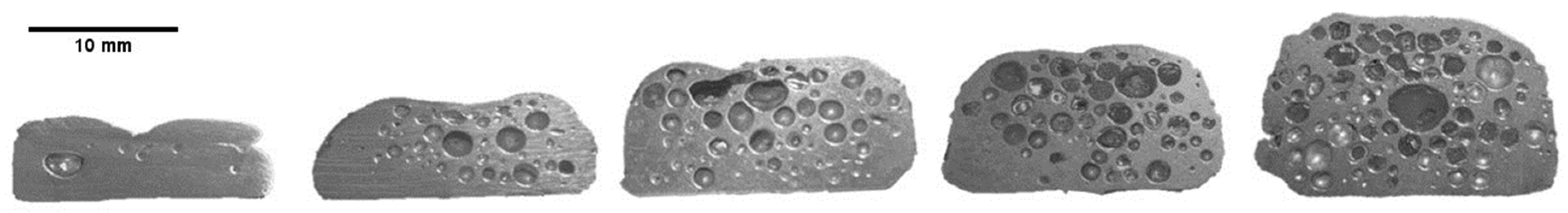
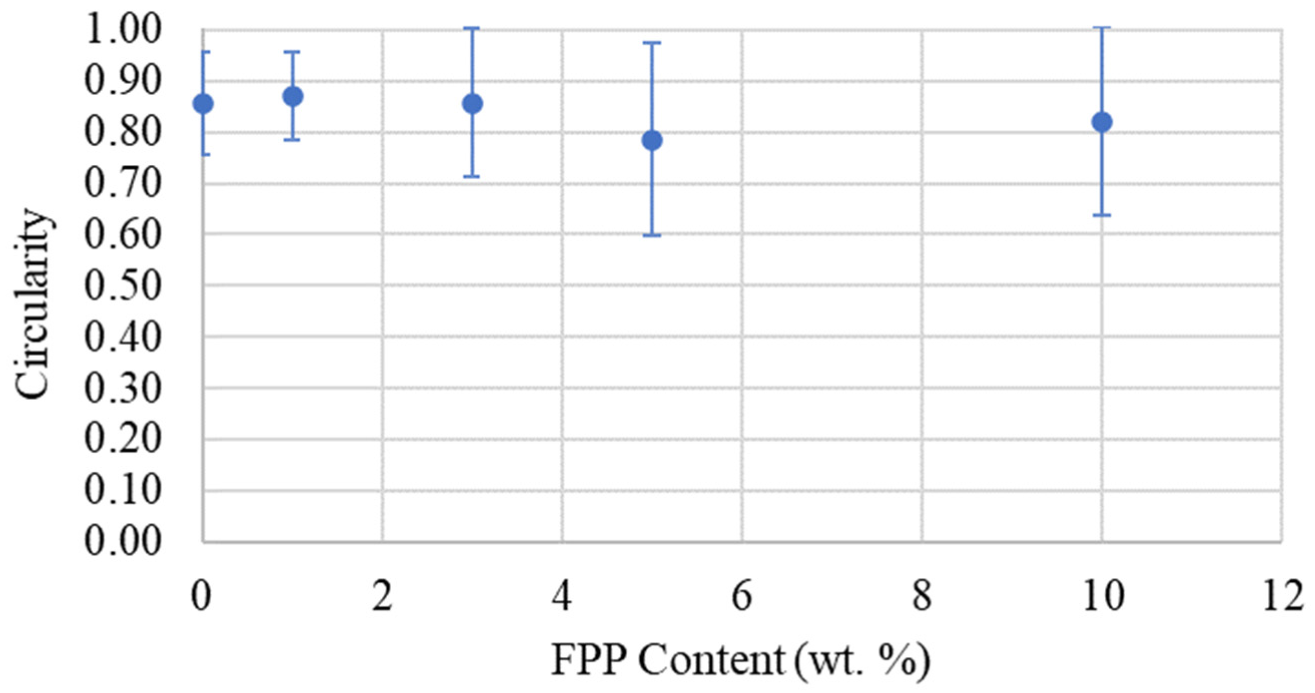
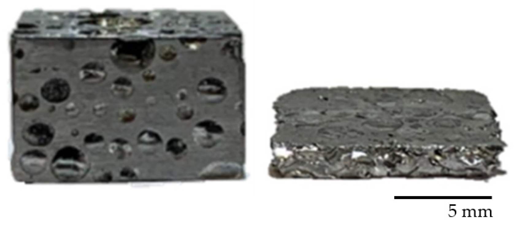
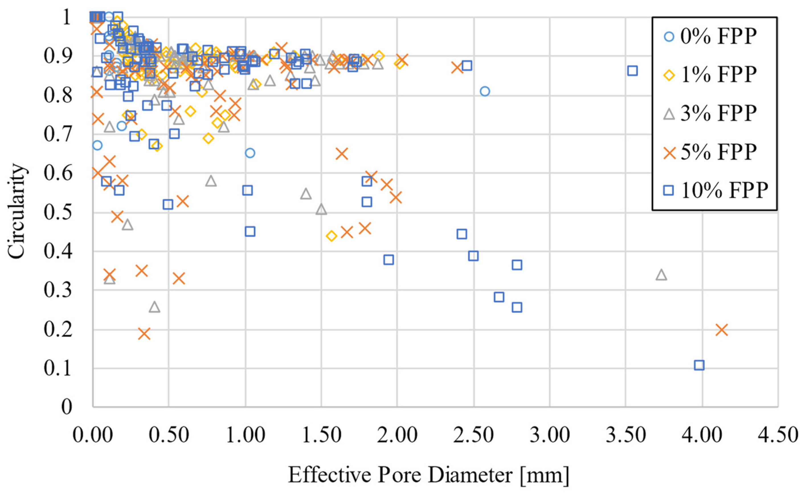
  • Al-TiH2 FPPs have been successfully used to process bulk aluminum closed cell foams with relatively high circularities.
  • Due to the localization of TiH2 within particles, the local TiH2 content was 2 wt.%, allowing for the generation of rounded voids despite the low overall TiH2 content for the foam.
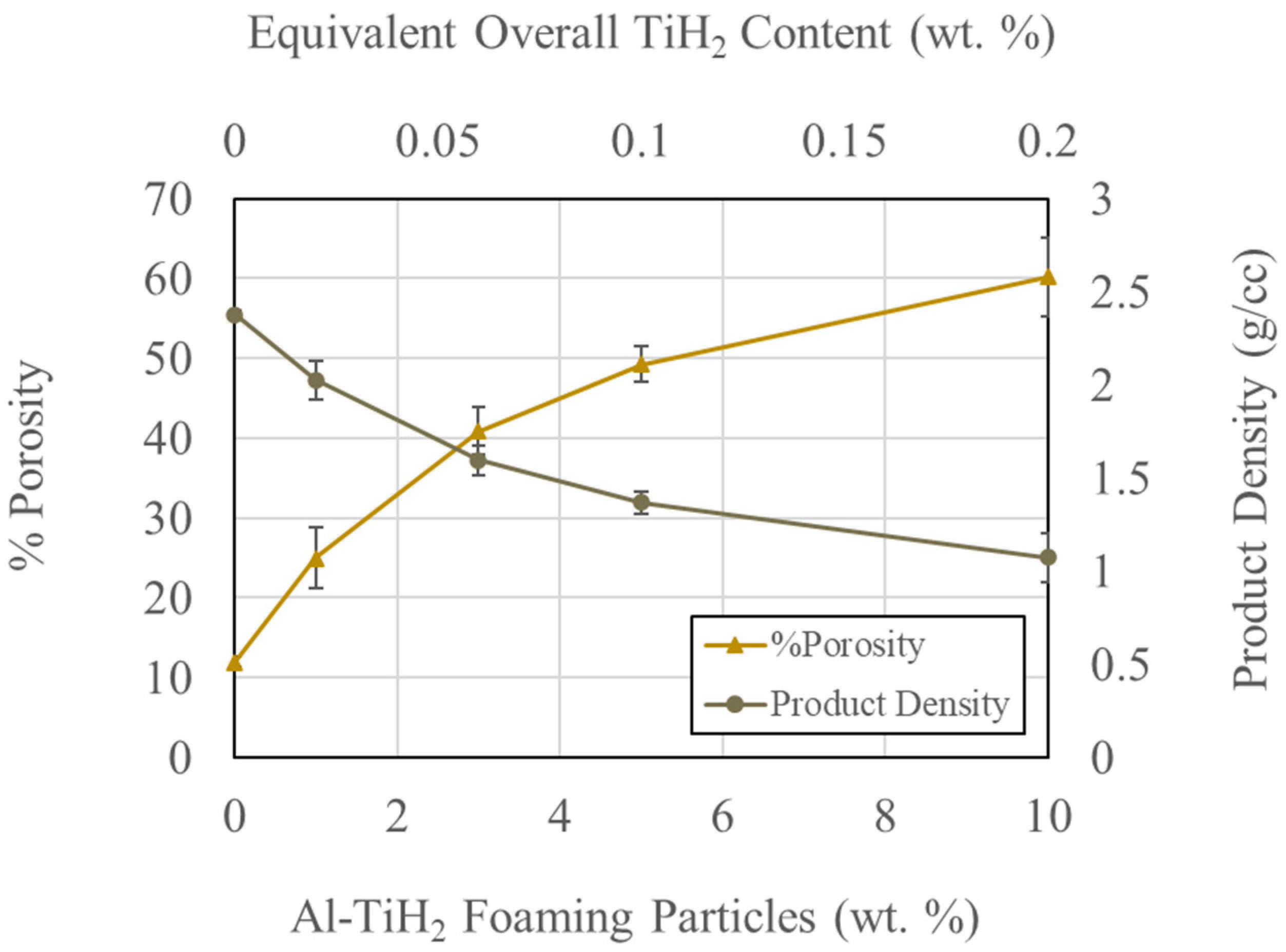
  • Under the investigated processing conditions, the highest foam porosity of 60% was obtained with an overall TiH2 content of 0.2 wt.% (equivalent to 10% composite FPP content).
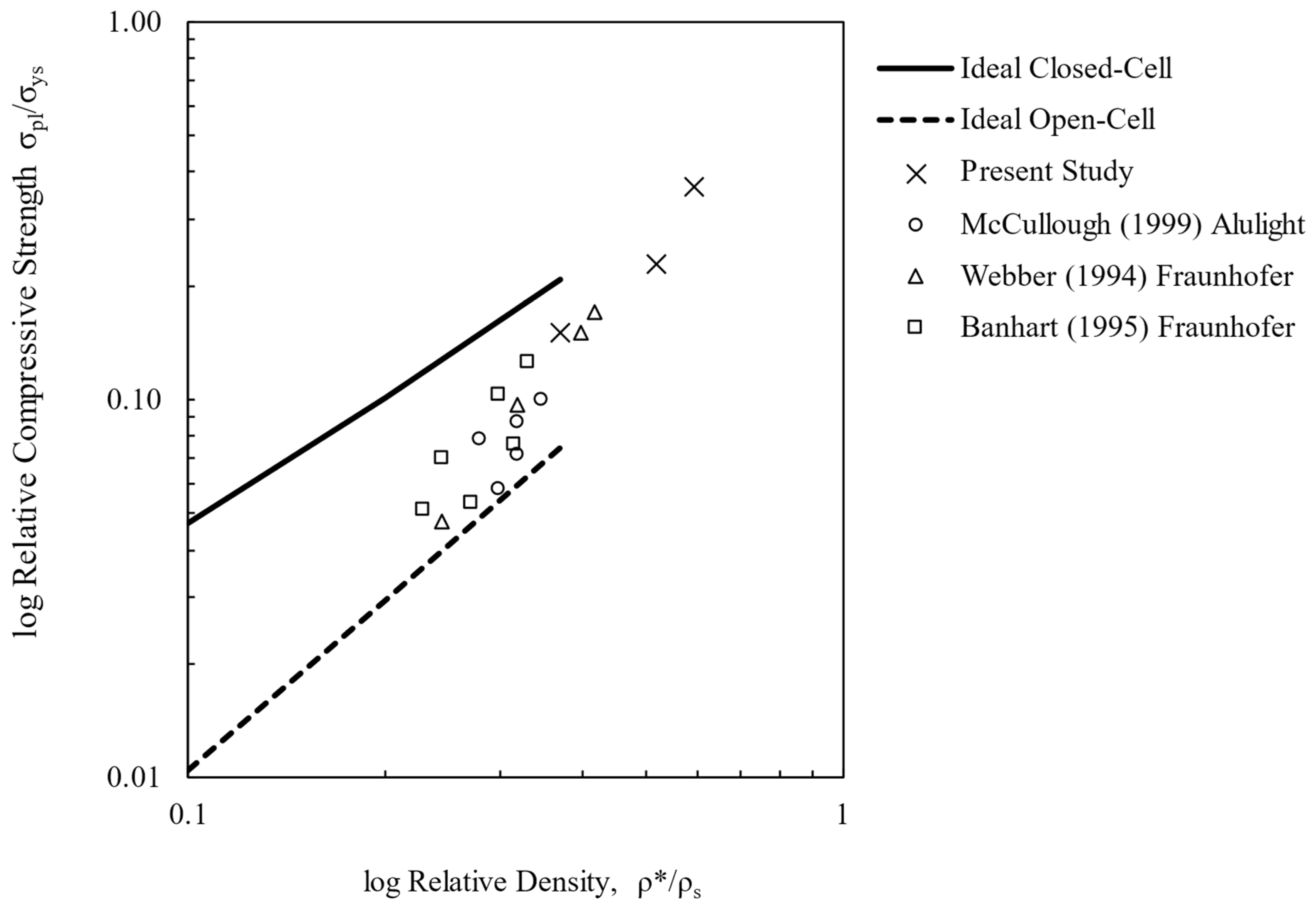
  • The relative strengths of the FPP foams investigated roughly fall in between the ideal open and ideal closed cell boundaries.
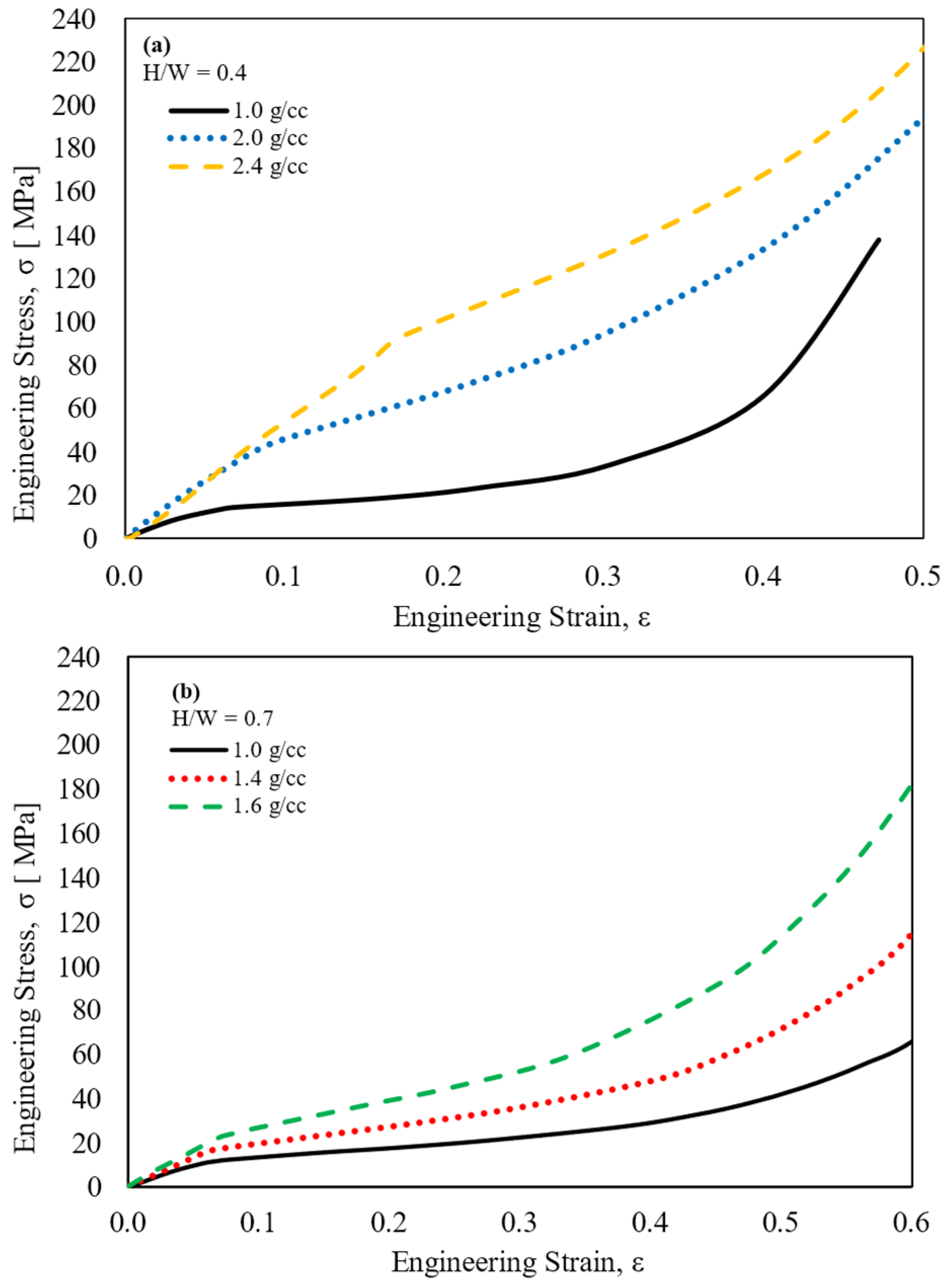
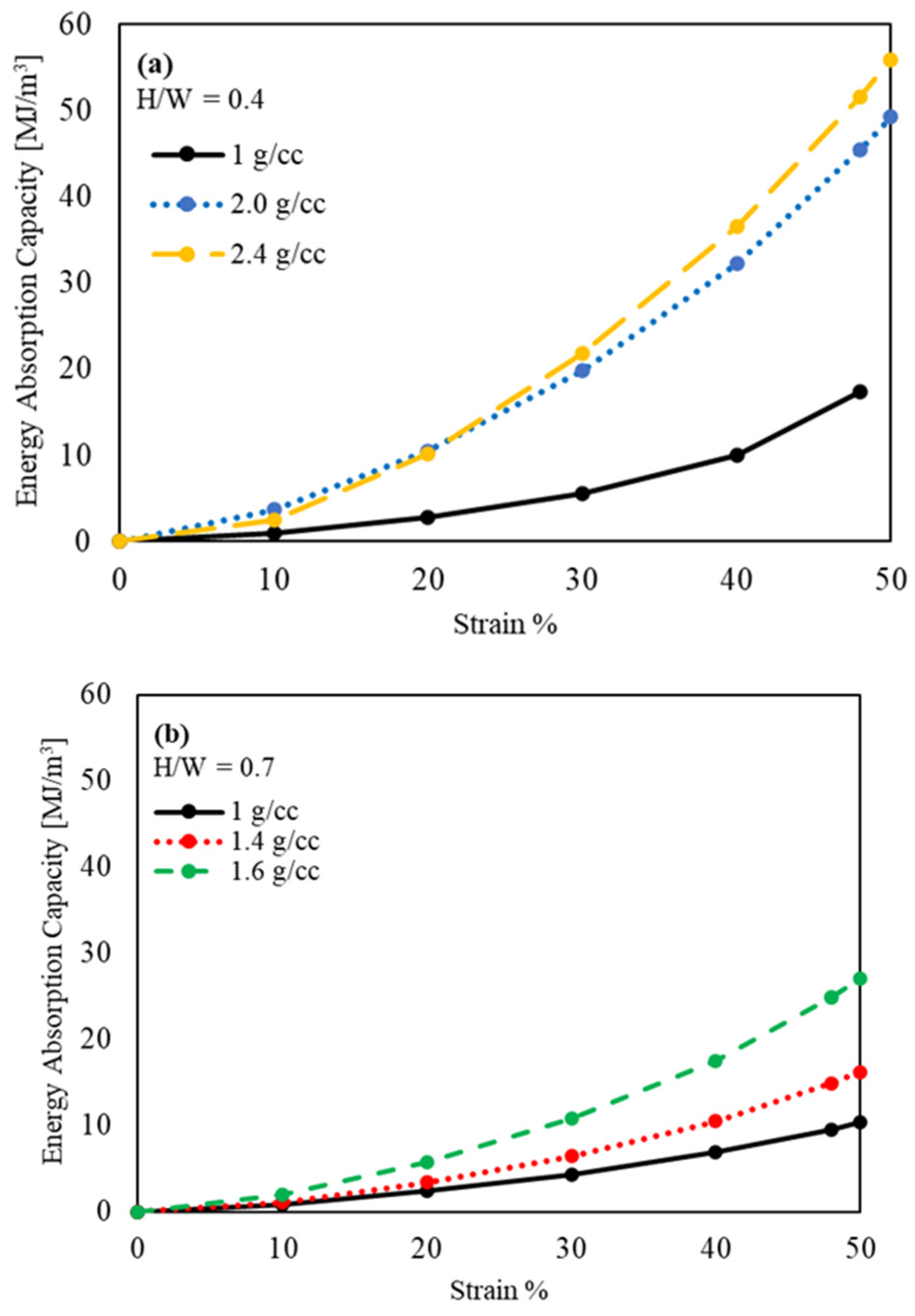
  • Products with 40–60% porosity were found to have energy absorption capacities of 10–25 MJ/m3 at 50% strain.
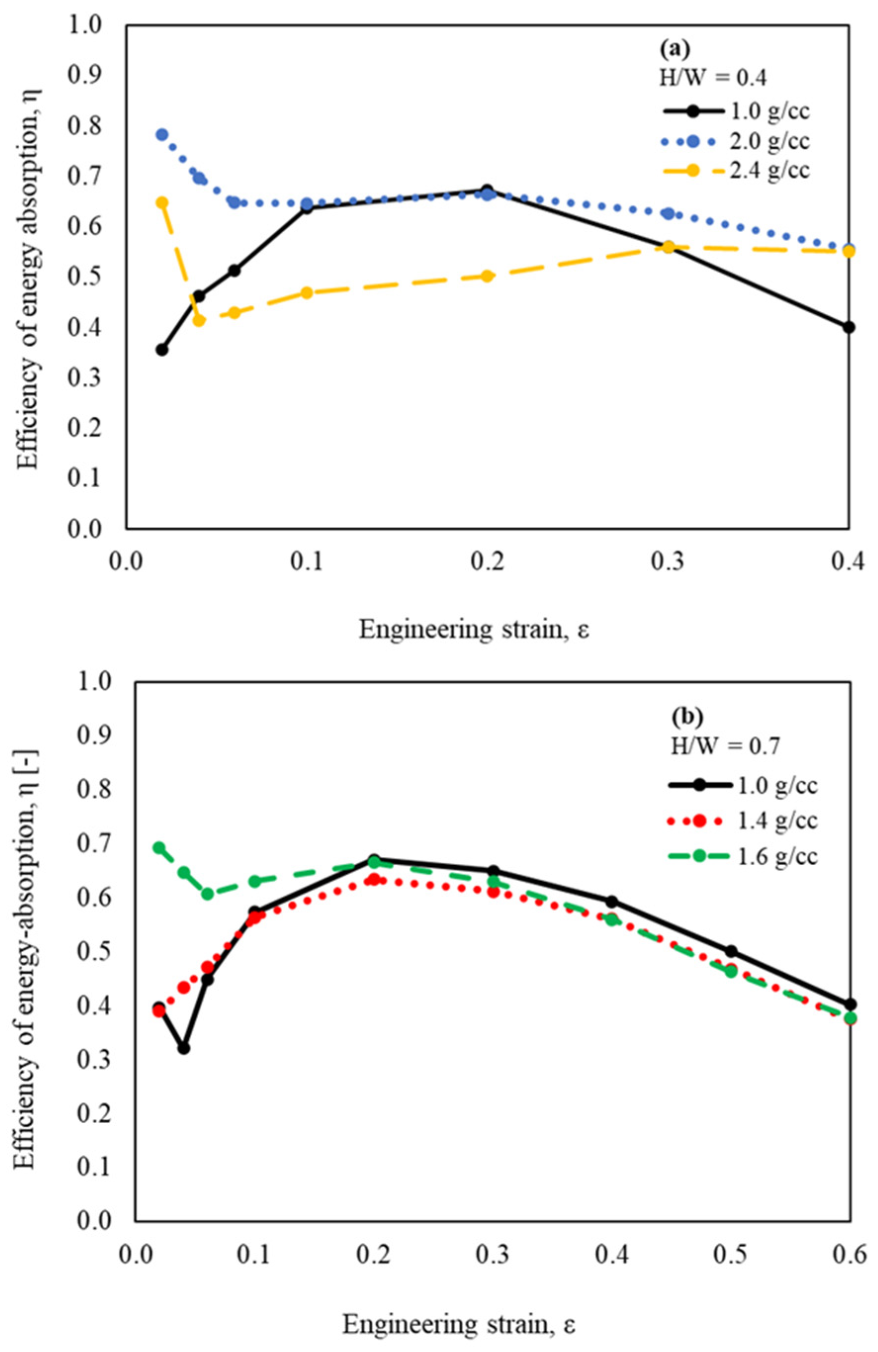
  • The maximum energy absorption efficiencies for foams with 40–60% porosity ranged from 0.6–0.7.
Future work will be directed at investigating Al-TiH2 FPPs of varying particle sizes, extended contents, and different cooling rates after foaming. Also, to improve the uniformity of pore sizes, classified Al-TiH2 powders will be investigated, where the FPP are of a uniform size (very narrow size distribution) to start with. Other aluminum matrices, such as AlSi8Mg4, will be investigated, which has been the most successful powder-based aluminum alloy closed cell foam produced using a blowing agent, and is also currently in commercial use [53,54]. It is expected that the major advantage of rounded pores is in the fatigue and fracture behaviors of the foams, which should be the subject of future FPP investigations.

Author Contributions

Conceptualization, K.M.; Formal analysis, A.M.; Investigation, A.M.; Resources, K.M.; Data curation, A.M.; Writing—original draft, A.M.; Writing—review & editing, A.M. and K.M.; Visualization, A.M.; Supervision, K.M.; Project administration, K.M.; Funding acquisition, K.M. All authors have read and agreed to the published version of the manuscript.

Funding

This research received no external funding.

Data Availability Statement

The raw data supporting the conclusions of this article will be made available by the authors on request.

Conflicts of Interest

The authors declare that there are no conflicts of interest.

References

  1. Dineshkumar, J.; Jesudas, T.; Elayaraja, R. Characteristics, Applications and Processing of Aluminium Foams—A Review. Mater. Today Proc. 2021, 42, 1773–1776. [Google Scholar] [CrossRef]
  2. Liu, P.S.; Ma, X.M. Property Relations Based on the Octahedral Structure Model with Body-Centered Cubic Mode for Porous Metal Foams. Mater. Des. 2020, 188, 108413. [Google Scholar] [CrossRef]
  3. Palka, K.; Adamek, G.; Jakubowicz, J. Compression Behavior of Ti Foams with Spherical and Polyhedral Pores. Adv. Eng. Mater. 2016, 18, 1511–1518. [Google Scholar] [CrossRef]
  4. Behymer, N.; Morsi, K. Review: Closed-Cell Metallic Foams Produced via Powder Metallurgy. Metals 2023, 13, 959. [Google Scholar] [CrossRef]
  5. Brothers, A.H.; Scheunemann, R.; DeFouw, J.D.; Dunand, D.C. Processing and Structure of Open-Celled Amorphous Metal Foams. Scr. Mater. 2005, 52, 335–339. [Google Scholar] [CrossRef]
  6. Kou, D.P.; Li, J.R.; Yu, J.L.; Cheng, H.F. Mechanical Behavior of Open-Cell Metallic Foams with Dual-Size Cellular Structure. Scr. Mater. 2008, 59, 483–486. [Google Scholar] [CrossRef]
  7. Morsi, K.; Krommenhoek, M.; Shamma, M. Novel Aluminum (Al)-Carbon Nanotube (CNT) Open-Cell Foams. Metall. Mater. Trans. A Phys. Metall. Mater. Sci. 2016, 47, 2574–2578. [Google Scholar] [CrossRef]
  8. Krommenhoek, M.; Shamma, M.; Morsi, K. Processing, Characterization, and Properties of Aluminum–Carbon Nanotube Open-Cell Foams. J. Mater. Sci. 2017, 52, 3927–3935. [Google Scholar] [CrossRef]
  9. Gibson, L.J. Mechanical Behavior of Metallic Foams. Annu. Rev. Mater. Sci. 2000, 30, 191–227. [Google Scholar] [CrossRef]
  10. Gibson, L.J.; Ashby, M.F. Cellular Solids: Structure and Properties, 2nd ed.; Cambridge University Press: Cambridge, UK, 2014. [Google Scholar]
  11. Kulshreshtha, A.; Dhakad, S.K. Preparation of Metal Foam by Different Methods: A Review. Mater. Today Proc. 2020, 26, 1784–1790. [Google Scholar] [CrossRef]
  12. Jiang, B.; Zhao, N.Q.; Shi, C.S.; Du, X.W.; Li, J.J.; Man, H.C. A Novel Method for Making Open Cell Aluminum Foams by Powder Sintering Process. Mater. Lett. 2005, 59, 3333–3336. [Google Scholar] [CrossRef]
  13. Wan, T.; Liu, Y.; Zhou, C.; Chen, X.; Li, Y. Fabrication, Properties, and Applications of Open-Cell Aluminum Foams: A Review. J. Mater. Sci. Technol. 2021, 62, 11–24. [Google Scholar] [CrossRef]
  14. Kevorkijan, V.; Škapin, S.D.; Paulin, I.; Šuštaršič, B.; Jenko, M. Synthesis and Characterisation of Closed Cells Aluminium Foams Containing Dolomite Powder as Foaming Agent. Mater. Technol. 2010, 44, 363–371. [Google Scholar]
  15. Ghaleh, M.H.; Ehsani, N.; Baharvandi, H.R. High-Porosity Closed-Cell Aluminum Foams Produced by Melting Method Without Stabilizer Particles. Int. J. Met. Cast. 2021, 15, 899–905. [Google Scholar] [CrossRef]
  16. Lázaro, J.; Solórzano, E.; Rodríguez-Pérez, M.A. Alternative Carbonates to Produce Aluminium Foams via Melt Route. Procedia Mater. Sci. 2014, 4, 275–280. [Google Scholar] [CrossRef]
  17. Asavavisithchai, S.; Kennedy, A.R. Effect of Powder Oxide Content on the Expansion and Stability of PM-Route Al Foams. J. Colloid Interface Sci. 2006, 297, 715–723. [Google Scholar] [CrossRef] [PubMed]
  18. Haesche, M.; Weise, J.; Garcia-Moreno, F.; Banhart, J. Influence of Particle Additions on the Foaming Behaviour of AlSi11/TiH2 Composites Made by Semi-Solid Processing. Mater. Sci. Eng. A 2008, 480, 283–288. [Google Scholar] [CrossRef]
  19. Deng, F.; Liu, Y.; Lu, X.; Fan, J. Improved Stability of Aluminum Foam Through Heat Treatment of Foamable Precursor. Met. Mater. Int. 2020, 26, 1596–1601. [Google Scholar] [CrossRef]
  20. Proa-Flores, P.M.; Mendoza-Suarez, G.; Drew, R.A.L. Effect of TiH2 Particle Size Distribution on Aluminum Foaming Using the Powder Metallurgy Method. J. Mater. Sci. 2012, 47, 455–464. [Google Scholar] [CrossRef]
  21. von Zeppelin, F.; Hirscher, M.; Stanzick, H.; Banhart, J. Desorption of Hydrogen from Blowing Agents Used for Foaming Metals. Compos. Sci. Technol. 2003, 63, 2293–2300. [Google Scholar] [CrossRef]
  22. Mukherjee, M.; Ramamurty, U.; Garcia-Moreno, F.; Banhart, J. The Effect of Cooling Rate on the Structure and Properties of Closed-Cell Aluminium Foams. Acta Mater. 2010, 58, 5031–5042. [Google Scholar] [CrossRef]
  23. Kennedy, A.R. The Effect of TiH2 Heat Treatment on Gas Release and Foaming in Al–TiH2 Preforms. Scr. Mater. 2002, 47, 763–767. [Google Scholar] [CrossRef]
  24. Matijasevic-Lux, B.; Banhart, J.; Fiechter, S.; Görke, O.; Wanderka, N. Modification of Titanium Hydride for Improved Aluminium Foam Manufacture. Acta Mater. 2006, 54, 1887–1900. [Google Scholar] [CrossRef]
  25. Romero-Romero, M.; Domínguez-Ríos, C.; Torres-Sánchez, R.; Aguilar-Elguezabal, A. Electroless Ni-B Coating onto TiH2 Powder: An Approach for a Simplified Surface Preparation. Surf. Coat. Technol. 2017, 315, 181–187. [Google Scholar] [CrossRef]
  26. Fang, J.; Ding, B.; Yang, Z.; Zhao, K.; Gu, C. The Effect of SiO2 and Al2O3 Coating on the Surface of TiH2 Powders on Gas Release. J. Colloid Interface Sci. 2005, 283, 1–4. [Google Scholar] [CrossRef] [PubMed]
  27. García-Moreno, F.; Banhart, J. Influence of Gas Pressure and Blowing Agent Content on the Formation of Aluminum Alloy Foam. Adv. Eng. Mater. 2021, 23, 2100242. [Google Scholar] [CrossRef]
  28. Duarte, I.; Banhart, J. A Study of Aluminium Foam Formation—Kinetics and Microstructure. Acta Mater. 2000, 48, 2349–2362. [Google Scholar] [CrossRef]
  29. German, R.M. Powder Metallurgy & Particulate Materials Processing; Metal Powder Industry Federation: Princeton, NJ, USA, 2005. [Google Scholar]
  30. Key, D.; Daoush, W.M.; Morsi, K. Processing of Microscale Aluminum Foamed Particles. Mater. Perform. Charact. 2020, 9, 442–451. [Google Scholar] [CrossRef]
  31. Morsi, K.; Daoush, W.M. Al-TiH2 Composite “Particles” as Foaming Precursors for Metallic Foams. Scr. Mater. 2015, 105, 6–9. [Google Scholar] [CrossRef]
  32. Neu, T.; Pfretzschner, B.; García-Moreno, F.; Banhart, J. Influence of the Heating Rate on the Foaming Behavior of Various Aluminium Alloys. Metals 2017, 7, 323. [Google Scholar] [CrossRef]
  33. Rasooli, A.; Boutorabi, M.A.; Divandari, M.; Azarniya, A. Effect of High Heating Rate on Thermal Decomposition Behaviour of Titanium Hydride (TiH2) Powder in Air. Bull. Mater. Sci. 2013, 36, 301–309. [Google Scholar] [CrossRef]
  34. Mukherjee, M.; García-Moreno, F.; Jiménez, C.; Rack, A.; Banhart, J. Microporosity in Aluminium Foams. Acta Mater. 2017, 131, 156–168. [Google Scholar] [CrossRef]
  35. Mukherjee, M.; Garcia-Moreno, F.; Jiménez, C.; Banhart, J. Al and Zn Foams Blown by an Intrinsic Gas Source. Adv. Eng. Mater. 2010, 12, 472–477. [Google Scholar] [CrossRef]
  36. Papantoniou, I.; Kyriakopoulou, H.P.; Pantelis, D.I.; Manolakos, D.E. Metal Foaming by Powder Metallurgy Process: Investigation of Different Parameters on the Foaming Efficiency. Frat. Ed Integrita Strutt. 2019, 13, 497–504. [Google Scholar] [CrossRef]
  37. Chethan, A.; Garcia-Moreno, F.; Wanderka, N.; Murty, B.S.; Banhart, J. Influence of Oxides on the Stability of Zinc Foam. J. Mater. Sci. 2011, 46, 7806–7814. [Google Scholar] [CrossRef]
  38. Wang, L.; Wang, Y.; You, X.; Wang, F. Foaming Behavior and Pore Structure Evolution of Foamed Aluminum under the Extrusion Constraint. Adv. Mater. Sci. Eng. 2020, 2020, 3948378. [Google Scholar] [CrossRef]
  39. Youn, S.W.; Kang, C.G. The Effect of Process Parameters on Cell Morphology in Cellular Aluminium Alloy Fabricated by Powder Compression and the Induction Heating Process. Proc. Inst. Mech. Eng. Part B J. Eng. Manuf. 2003, 217, 201–211. [Google Scholar] [CrossRef]
  40. Prosviryakov, A.S.; Solonin, A.N.; Churyumov, A.Y.; Mantesevich, N.M.; Kolerov, L.V. On the Effect of Oxidative Milling of Matrix Powder on the Structure and Properties of Aluminum Foam Based on the Al-Si Alloy. Phys. Met. Metallogr. 2022, 123, 491–498. [Google Scholar] [CrossRef]
  41. Gokhale, A.; Ravi Kumar, N.; Sudhakar, B.; Sahi, S.N.; Basumatary, H.; Dhara, S. Cellular Metals and Ceramics for Defence Applications. Def. Sci. J. 2011, 61, 567–575. [Google Scholar] [CrossRef]
  42. ISO 13314:2011; Mechanical Testing of Metals—Ductility Testing—Compression Test for Porous and Cellular Metals. International Organization for Standardization: Geneva, Switzerland, 2011.
  43. Hassanli, F.; Paydar, M.H. Improvement in Energy Absorption Properties of Aluminum Foams by Designing Pore-Density Distribution. J. Mater. Res. Technol. 2021, 14, 609–619. [Google Scholar] [CrossRef]
  44. Yang, X.; Hu, Q.; Du, J.; Song, Z.; Zou, T.; Sha, J.; He, C.; Zhao, N. Compression Fatigue Properties of Open-Cell Aluminum Foams Fabricated by Space-Holder Method. Int. J. Fatigue 2019, 121, 272–280. [Google Scholar] [CrossRef]
  45. Li, C.; Li, C.; Wang, Y. Compressive Behavior and Energy Absorption Capacity of Unconstrained and Constrained Open-Cell Aluminum Foams. Adv. Compos. Lett. 2020, 29, 2633366X20923671. [Google Scholar] [CrossRef]
  46. Yu, H.; Guo, Z.; Li, B.; Yao, G.; Luo, H.; Liu, Y. Research into the Effect of Cell Diameter of Aluminum Foam on Its Compressive and Energy Absorption Properties. Mater. Sci. Eng. A 2007, 454–455, 542–546. [Google Scholar] [CrossRef]
  47. Baumeister, J.; Banhart, J.; Weber, M. Aluminium Foams for Transport Industry. Mater. Des. 1997, 18, 217–220. [Google Scholar] [CrossRef]
  48. Youn, S.W.; Kang, C.G. Fabrication of Foamable Precursors by Powder Compression and Induction Heating Process. Metall. Mater. Trans. B 2004, 35, 769–776. [Google Scholar] [CrossRef]
  49. Nava, M.G.; Cruz-Ramirez, A.; Rosales, M.A.S.; Gutierrrez-Perez, V.H.; Sanchez-Martenez, A. Fabrication of Aluminum Alloy Foams by Using Alternative Thickening Agents via Melt Route. J. Alloys Compd. 2017, 698, 1009–1017. [Google Scholar] [CrossRef]
  50. Yu, Y.; Cao, Z.; Tu, G.; Mu, Y. Energy Absorption of Different Cell Structures for Closed-Cell Foam-Filled Tubes Subject to Uniaxial Compression. Metals 2020, 10, 1579. [Google Scholar] [CrossRef]
  51. Wei, P.; Liu, L. Influence of Density on Compressive Properties and Energy Absorption of Foamed Aluminum Alloy. J. Wuhan Univ. Technol. Mater. Sci. Ed. 2007, 22, 225–228. [Google Scholar] [CrossRef]
  52. Asavavisithchai, S.; Prapajaraswong, A. Utilization of Power Plant Bottom-Ash Particles as Stabilizer in Aluminum Foams. Mater. Test. 2013, 55, 602–606. [Google Scholar] [CrossRef]
  53. Kamm, P.H.; Neu, T.R.; García-Moreno, F.; Banhart, J. Nucleation and Growth of Gas Bubbles in AlSi8Mg4 Foam Investigated by X-Ray Tomoscopy. Acta Mater. 2021, 206, 116583. [Google Scholar] [CrossRef]
  54. García-Moreno, F.; Radtke, L.A.; Neu, T.R.; Kamm, P.H.; Klaus, M.; Schlepütz, C.M.; Banhart, J. The Influence of Alloy Composition and Liquid Phase on Foaming of Al–Si–Mg Alloys. Metals 2020, 10, 189. [Google Scholar] [CrossRef]
Figure 1. (a) Al-TiH2 FPPs (produced by milling Al and TiH2 for 1.5 h) and (b) a higher magnification micrograph showing dispersed TiH2 (white) within a composite Al-TiH2 FPP.
Metals 14 00120 g001
Figure 2. Cross-sectioned foamed products of 0, 1, 3, 5, and 10 wt.% Al-TiH2 composite particle content (from left to right), which is equivalent to 0, 0.02, 0.06, 0.1, and 0.2 overall wt.% TiH2, respectively. Products were foamed at 740 °C.
Metals 14 00120 g002
Figure 3. Room temperature product density and porosity (with standard deviations) for foamed products foamed at 740 °C.
Metals 14 00120 g003
Figure 4. Pore size distributions for foams produced with an FPP content of (a) 0, (b) 1, (c) 3, (d) 5, and (e) 10%.
Metals 14 00120 g004
Figure 5. Average pore circularity with increasing FPP content.
Metals 14 00120 g005
Figure 6. Pore circularity vs. effective pore diameter.
Metals 14 00120 g006
Figure 7. Al foam before and after compression testing.
Metals 14 00120 g007
Figure 8. Three regions of compression deformation of Al foam with density 1.0 g/cc and H/W = 0.7: I, elastic region; II, compressive plateau region; III, densification region.
Metals 14 00120 g008
Figure 9. Room temperature compressive stress/strain curve for foam with H/W ratios of (a) 0.4 and (b) 0.7.
Metals 14 00120 g009
Figure 10. Room temperature relative compressive strength of FPP foams compared to ideal open- and closed-cell foams and other aluminum foams formed via powder metallurgy processing routes by way of titanium hydride. Adapted from ref. [9].
Metals 14 00120 g010
Figure 11. Room temperature energy absorption capacity for foam with H/W ratios of (a) 0.4 and (b) 0.7.
Metals 14 00120 g011
Figure 12. Room temperature energy absorption efficiency for foam with H/W ratios of (a) 0.4 and (b) 0.7.
Metals 14 00120 g012
Table 1. Characteristics of foamed specimens for compression testing.
GroupH/W RatioFPP Content wt.%Overall wt.% TiH2Mean Density (g/cc)Mean Porosity %
A0.400.002.412
10.022.025
100.201.060
B0.730.061.641
50.101.449
100.201.060
Disclaimer/Publisher’s Note: The statements, opinions and data contained in all publications are solely those of the individual author(s) and contributor(s) and not of MDPI and/or the editor(s). MDPI and/or the editor(s) disclaim responsibility for any injury to people or property resulting from any ideas, methods, instructions or products referred to in the content.

