Article

The Feasibility of Static Shoulder Friction Stir Welding in Joining Dissimilar Metals of Al6061 and Ti6Al4V

1
Department of Mechanical Engineering, National Institute of Technology, Warangal 506004, India
2
Arbegast Materials Processing and Joining Laboratory (AMP), South Dakota School of Mines & Technology, Rapid City, SD 57701, USA
3
Department of Mechanical Engineering, Sardar Vallabhbhai National Institute of Technology, Surat 395007, India
*
Authors to whom correspondence should be addressed.
Metals 2024, 14(1), 128; https://doi.org/10.3390/met14010128
Submission received: 30 November 2023 / Revised: 2 January 2024 / Accepted: 15 January 2024 / Published: 21 January 2024
(This article belongs to the Section Welding and Joining)

Abstract

:
In this study, static shoulder friction stir welding (SSFSW) is innovatively employed to join Al6061 and Ti6Al4V, aiming to minimize material mixing and intermetallic formation, significantly influencing the interfacial microstructure and joint strength. The results revealed that SSFSW reduced the intermetallic layer thickness at the interface, improving joint quality. The mutual interdiffusion of Al and Ti at the interface was influenced by an exothermic chemical reaction, forming an Al5Ti2–Al3Ti sequence due to the diffusion of Al into the Ti matrix. The microstructural analysis demonstrated better interfacial microstructural homogeneity in SSFSW joints than conventional FSW (CFSW), with finer titanium particle distribution. The larger particles resulted in coarser grains in CFSW, affecting the mobility of dislocations, which potentially led to the inhomogeneous concentration of dislocations at the interface. Recrystallization mechanisms varied between CFSW and SSFSW, with the Ti interface showing equiaxed and recrystallized grains due to the dynamic recovery driven by adiabatic shear bands. The tensile testing results of SSFSW exhibited a joint efficiency of 88%, demonstrating a 20.2% increase compared to CFSW, which can be attributed to differences in fracture modes. This study contributes to an understanding of dissimilar Al-Ti joining and provides insights for industries seeking to leverage the benefits of such combinations in lightweight and high-performance structures.

1. Introduction

The demand for joining dissimilar materials and multicomponent structures has surged in modern engineering applications to optimize performance and functionality. Joining dissimilar materials incorporates different complementary properties, leading to an overall improvement in mechanical, thermal, and corrosion resistance properties in the final product. The combination of aluminum (Al) and titanium (Ti) has recently attracted attention for its potential use in lightweight structures due to their excellent specific strength, making it attractive to industries such as automobile, aviation, and aerospace [1]. However, the dissimilar joining of Al and Ti presents challenges due to the inherent differences in physical properties, thermal properties, mechanical properties, and processing conditions [2]. Therefore, there is a need for suitable joining techniques to create strong and reliable joints between Al and Ti.
Among the available joining methods, friction stir welding (FSW) has gained considerable attention for dissimilar joining because it is a solid-state welding method free from environmental contamination. FSW employs a rotating, non-consumable tool that generates frictional heat and mechanical deformation, which results in a defect-free weld with considerable mechanical mixing at the joining interface [3,4,5]. During conventional welding of Al and Ti, intermetallic compounds (IMCs) can form at the joining interface and any other Al/Ti interface due to the elemental diffusion of Al into the Ti matrix [6]. The presence of IMCs offers advantages and challenges in dissimilar welds. Excessive IMC formation, with a thickness exceeding 5 µm, can deteriorate tensile and fatigue properties [7]. Considering the binary phase diagram, the formation of IMCs cannot be avoided. However, it is important to note that a thin layer of IMCs is crucial for bonding different materials in dissimilar welds. Thus, preventing a continuous, thick IMC layer holds significant importance.
Achieving high-strength dissimilar joints requires experimentation with effective FSW process conditions to minimize material mixing and processing temperature [8,9]. Several studies have explored the influence of process parameters, such as tool offset [10], welding speed [11], rotational speed [12], and the number of multi-passes [13,14], on IMC formation in Al-Ti FSW joints. Li et al. [15] observed poor joint strength due to massive IMC formation from Al and Ti intermixing. On the other hand, Kar et al. [16,17] demonstrated that mechanical intermixing plays a crucial role in establishing strong mechanical interlocking at the Al/Ti interface. This intermixing facilitates the formation of an intercalated structure, leading to enhanced mechanical properties. Chen and Nakata [18] highlighted the significant impact of the welding speed on the interfacial characteristics of Al-Ti FSW joints. Increasing rotational speed and thereby increasing the peak temperature led to thicker intermetallic layers beyond the critical thickness of 5 μm, negatively affecting mechanical properties, especially tensile properties [19].
To address these challenges, a relatively new variant of FSW, known as static shoulder friction stir welding (SSFSW), was developed [20]. This technique explicitly targets welding from low thermal conductivity Ti alloys, aiming to decrease temperature gradients across plate thickness [21]. This approach enhances low-temperature deformation and diminishes the heat flow into welding materials, consequently reducing the formation of IMCs [20,21,22]. SSFSW involves holding the tool’s shoulder stationary during welding, reducing the maximum temperature range reached. Notably, SSFSW minimizes the material flow near the interface when the shoulder rotation ceases [23,24,25]. This principle offers inherent benefits, including a lower process temperature and reduced material mixing when welding dissimilar materials. Zhao et al. [26] demonstrated the effect of SSFSW on joining dissimilar Al to Cu joints, reporting a 15.1% increase in strength by reducing the stress concentration resulting from material mixing. However, the significance of SSFSW in Al-Ti joints and other material combinations remains relatively unexplored.
This study aims to enhance dissimilar Al-Ti joints’ interfacial microstructure and mechanical properties using an indigenously built SSFSW tool. The objective of this study is to comprehensively evaluate the impact of SSFSW on interfacial microstructure and mechanical properties of Al-Ti dissimilar joints. These findings have significant implications for industrial applications aiming to harness the advantages of dissimilar Al-Ti combinations. This research facilitates the production of lightweight, high-performance structures, opening avenues for diverse engineering applications.

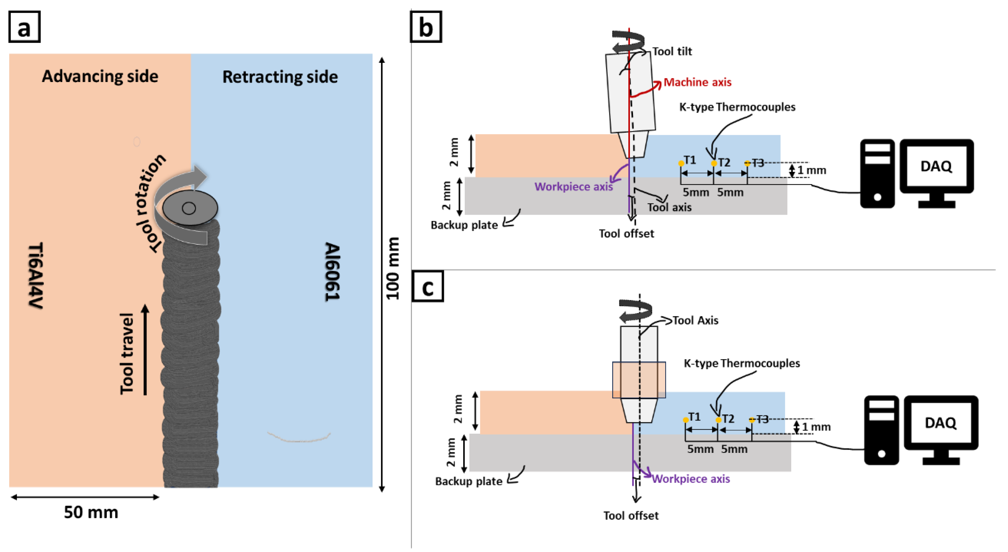
2. Materials and Methods

Al6061-T6 and Ti6Al4V were the materials investigated in this study. The Al6061, in its T6 state, showcased a characteristic structure from cold rolling, displaying elongated grains oriented along both transverse and rolling axes, as depicted in Figure 1a. An analysis using electron backscattered diffraction (EBSD) revealed an average grain dimension of 23.93 μm, accompanied by 61.4% of low-angle grain boundaries (LAGBs). On the other hand, the initial state of Ti6Al4V presented equiaxed grains. Specifically, the α-phase constituted 78.9% by volume, with an average grain size of 3.96 μm and 78.23% LAGBs, as shown in Figure 1b. Further insights into the elemental compositions of these base materials in their initial states can be found in Table 1. An indigenous SSFSW tool was designed and developed for joining dissimilar materials, as described in the previous studies [21]. The joint configuration used in this study is shown in Figure 2, and the process parameters used in this study are also outlined in Table 2. Ti6Al4V was kept on the advancing side during this investigation to prevent cracking, Al melting, and other defects in the final weld.
After welding, the samples were cut along the transverse direction using a wire-cut EDM machine. Standard metallurgical processes were applied, followed by macro and microstructural analysis using a 3D optical microscope (“HRM300”, Huvitz, Anyang-si, Republic of Korea) and scanning electron microscope (SEM) (“SIGMA 500VP”, St. Louis, MO, USA) with energy-dispersive spectroscopy. A microstructural evolution was examined using electron back-scattered diffraction (EBSD) (“FEI, Quanta 3D-FEGTM”, Lausanne, Switzerland), and phase analysis was conducted using an X-ray diffractometer (XRD) (“X’pert PANalytical”, Malvern, UK). Interfacial characteristics were analyzed using a high-resolution transmission electron microscope (HR-TEM) (“JEM 2100”, JEOL Ltd., Tokyo, Japan). The size of Ti particles observed using SEM was measured using Image J (v1.54h) software. Tensile tests were performed at room temperature using a universal tensile testing machine (“Fine spray India, M-50”, Bangalore, India) at a 0.2 mm/min crosshead speed. The fractured samples were again studied using SEM to understand the failure mechanism.

3. Results and Discussion

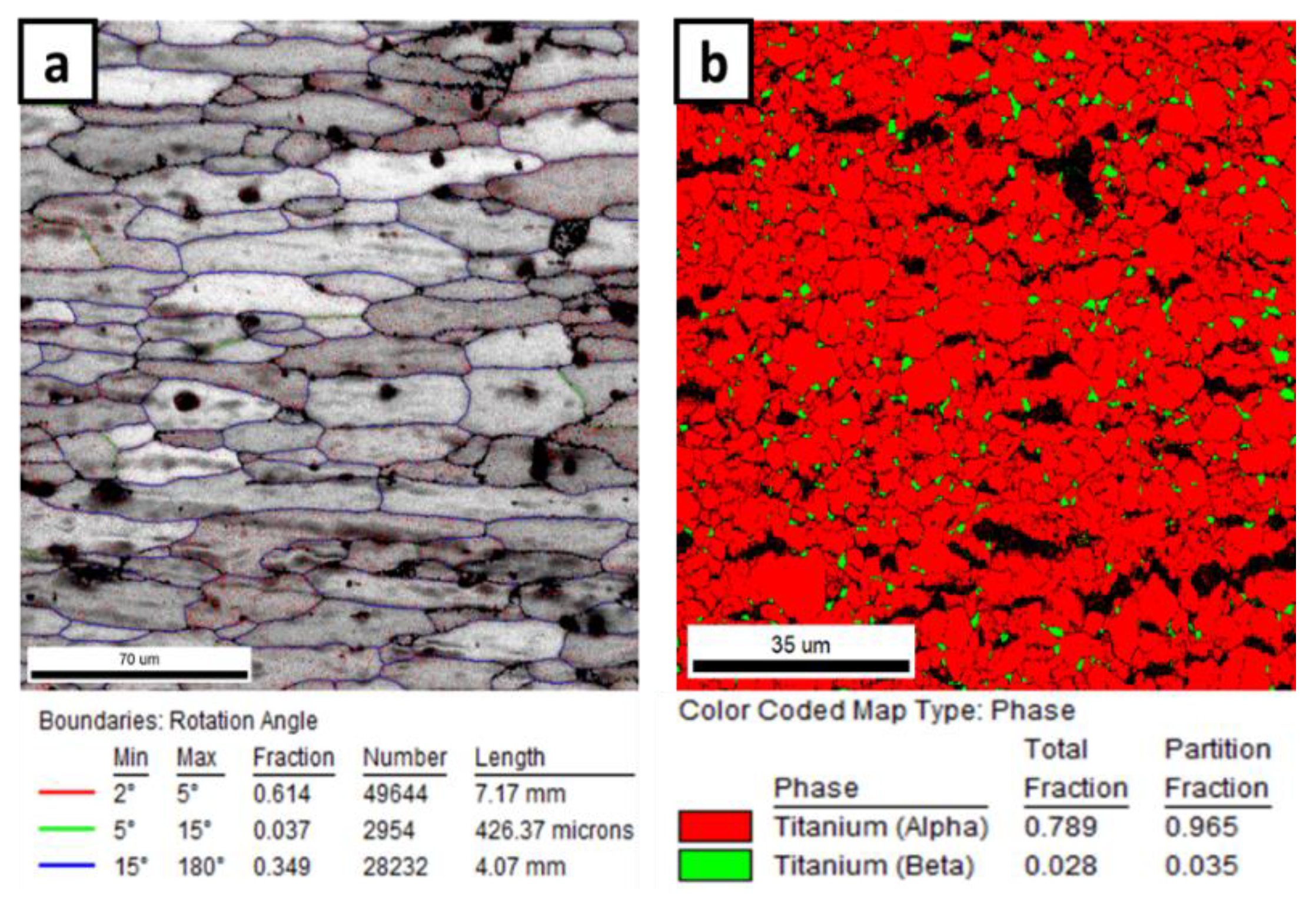
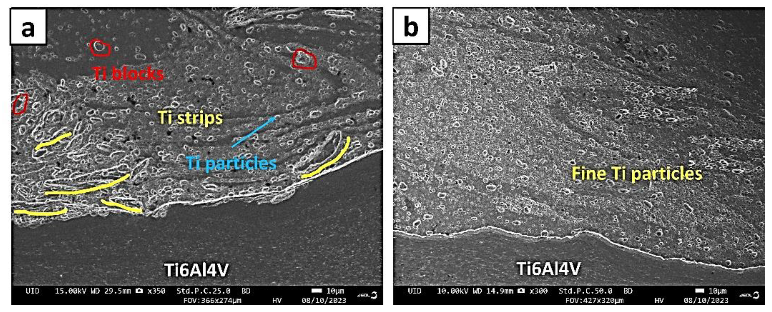
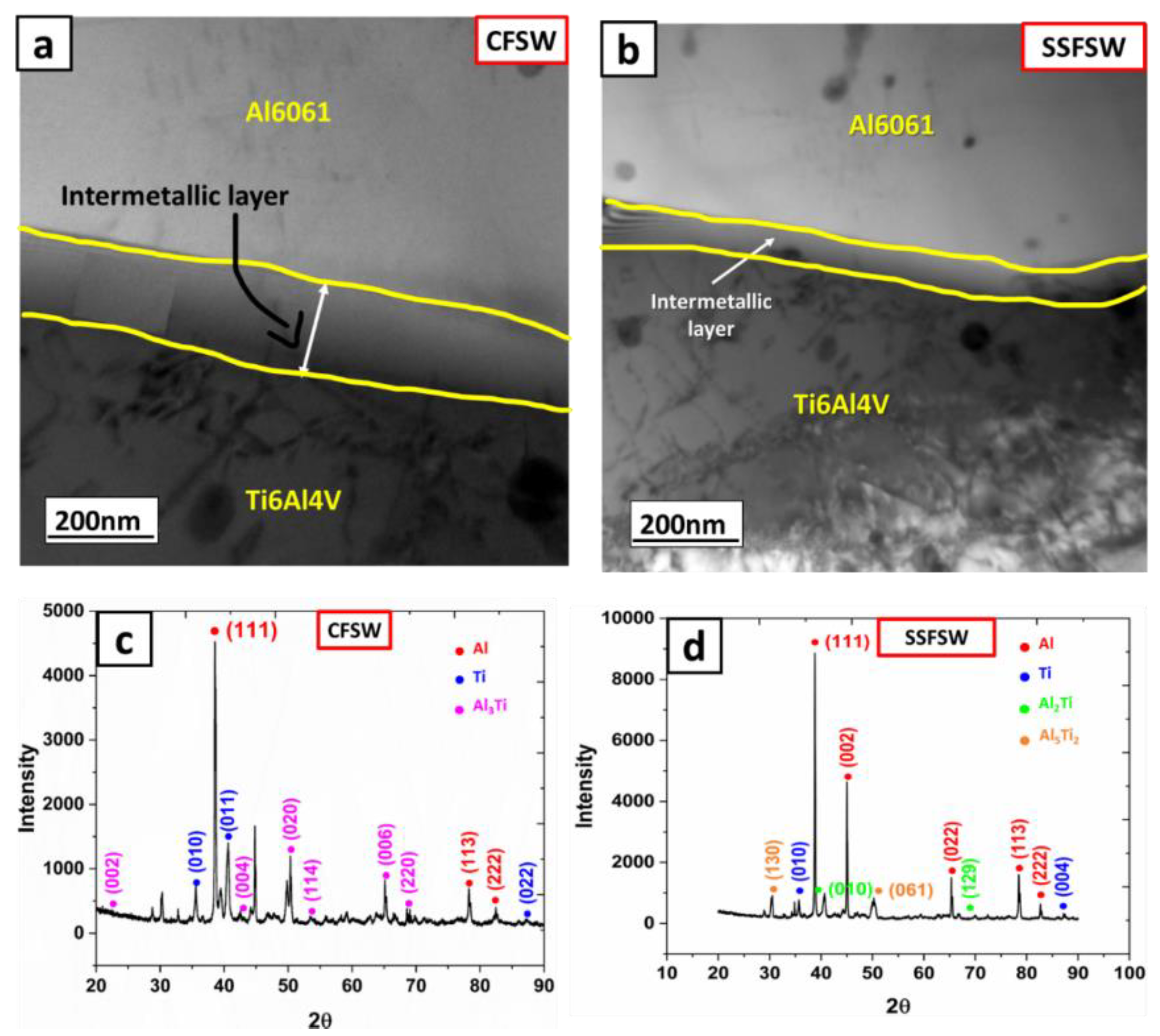
3.1. Interfacial Microstructural Characteristics

Controlling the rise in temperature is critical to achieving sound welds during dissimilar FSW processes. Mainly, when dealing with dissimilar materials, temperature control becomes even more crucial due to the influence of lower melting point materials [27]. So, in this study, the tool pin was strategically positioned with a 2.0 mm offset to the interface of the dissimilar metals on the Al side. This positioning allowed Al6061, with its lower melting point than Ti6Al4V, to effectively regulate the rise in temperature throughout the welding process. To accurately monitor the temperature dynamics, K-type thermocouples were located at different locations of 15 mm (T1), 20 mm (T2), and 25 mm (T3) from the joint line, as well as 1 mm from the bottom surface of the Al plate. The recorded temperature profiles during CFSW (Figure 3a) and SSFSW (Figure 3b) yielded maximum temperatures of 491 °C and 371 °C, respectively, at the thermocouple T1. A closer examination of the initial dwelling stage revealed that, in CFSW, the rate of the temperature rise at all thermocouples exhibited similar trends, and during SSFSW, the temperatures showed notable differences in a relative increase in the weld peak temperature and rate of temperature rise for all thermocouples. This discrepancy is due to the absence of frictional heat caused by the non-rotating shoulder in SSFSW. By extrapolating the slope between the peak temperature and a 2 mm offset tool, the predicted weld temperatures were 617 °C and 512 °C for CFSW and SSFSW, respectively.
The observed temperature ranges hold significant implications for the material properties involved in this study. The temperatures reached during this study were insufficient to plasticize titanium, as its yield strength at this temperature range was approximately 353 MPa [28], which is 37% of the tensile strength of Ti at room temperature. This signifies that Ti undergoes deformation at low homologous temperatures and higher strain levels. As a result, Ti experiences severe plastic deformation, during which a portion of the energy is converted into heat, which becomes concentrated at the interaction sites. This concentrated heat source facilitates the development of distinct layering patterns, as depicted in Figure 4a,b. As referenced in the existing literature, these patterns are called adiabatic shear bands [29,30,31]. Figure 4 also illustrates how the width of these shear bands diminishes progressively towards the retraction side. The tool offset influences these bands’ dimensions, subsequently impacting the size of the fragmented Ti particles observed. Specifically, measurements indicate an average width of approximately 14.16 µm for CFSW and 8.23 µm for SSFSW. Observations from the micrograph in Figure 4 also suggest that the individual layer widths are more pronounced in CFSW than in SSFSW. This distinction arises due to the diminishing width of these layers, which is attributable to reductions in ambient temperature and concurrent increases in the strain rate [32].
The formation of these adiabatic shear bands has critical ramifications, as they serve as sites for initiating microcracks and uncontrolled failure. Furthermore, the fracture behavior of Ti-6Al-4V is influenced by the local strain and stress gradients [32]. Depending on the contact surface with the tool pin and shoulder, these cracks promote material fracture during FSW and form Ti particles of varying sizes. As illustrated in Figure 5, the SEM micrographs demonstrate that the CFSW interface exhibits larger Ti particles in the form of strips and blocks. In contrast, the presence of Ti particles decreases at the SSFSW interface, with only a few fine Ti particles remaining. This observation indicates the extent of Ti’s interaction at the interface. During CFSW, the stirring action of the tool’s shoulder generates more frictional heat, resulting in increased heat generation and prolonged thermal exposure. Additionally, the rotating motion of the shoulder induces a greater frictional force, leading to a more pronounced impact on the Ti material near the interface. In contrast, during SSFSW, the shoulder glides parallel to the welding direction without rotation, minimizing its interaction with the Ti material. This suggests that SSFSW significantly benefits from reducing material mixing during welding.
The Ti particles dispersed within the Al matrix serve as dispersoids and provide nuclei for particle-stimulated nucleation (PSN). These Ti particles also act as physical barriers, impeding the growth of existing grains near the interface in both cases, but the effectiveness of PSN primarily depends on the size and uniform distribution of these particles [34]. The average size of Ti particles at the interface was measured using Image J software, yielding values of 7.2 ± 0.6 µm for CFSW and 2.7 ± 0.7 µm for SSFSW. The finer particles in SSFSW create a higher density of nucleation sites for Al atoms, potentially resulting in smaller grain sizes. To confirm this, EBSD analysis was conducted at the interface, and the inverse pole figure maps of both CFSW and SSFSW, illustrating the area fraction of grain size, are presented in Figure 6. The figure reveals distinct zones in both processes: the heat-affected zone, the stir zone, and a transition zone at the interface. As previously mentioned, the movement of the tool over the material’s edges generates a significant amount of frictional heat. The low thermal conductivity of Ti results in a noticeable thermal gradient across the interface, leading to the formation of these different zones. At the interface, an average grain size of 2.005 µm with 57.7% of low-angle grain boundaries (LAGBs) was observed for SSFSW, while CFSW exhibited an average grain size of 2.964 µm with 51.89% LAGBs. The grains in CFSW appear as small laminar structures, whereas in SSFSW, the grains in the corresponding regions are elongated towards the top of the joint.
FSW is a complex process that combines both normal and tangential forces to achieve a high-quality weld. The rotating tool applies a normal force that induces shear deformation at the interface and a tangential force that generates frictional heating to initiate plastic deformation. The material undergoes a combination of stretching, compression, and torsion due to the intricate action of the tool, resulting in lattice defects like dislocations. The mobility and rearrangement of these dislocations notably affect the interfacial strength and strain-hardening behavior of the weldments. This influence is directly linked to the level of plastic deformation and the generation of frictional heat. In CFSW, excessive heat causes extensive plasticization and flow, accommodating more dislocations and promoting static recrystallization [35]. Furthermore, numerous large Ti particles in CFSW affect its mobility and interaction, resulting in a higher concentration of dislocations at the interface, which may contribute to a weaker weld and the formation of interfacial defects [34]. On the other hand, the absence of shoulder rotation in SSFSW allows for a more controlled dislocation count during plastic deformation. Additionally, the smaller and more refined the Ti particles are in SSFSW, the more they contribute to enhanced dislocation mobility. To depict the dislocation density visually, kernel average misorientation (KAM) maps are generated, as illustrated in Figure 7. Consequently, the KAM maps of CFSW exhibit higher misorientation values than SSFSW, indicating the presence of an increased dislocation density and residual stresses at the interface of CFSW. A comparison of microstructural data (Figure 5) and KAM distribution maps reveals that higher misorientation angles are primarily concentrated near the Ti particles.

3.2. Mechanisms Associated with the Recrystallization of Ti and Al

The formation of finer grains and the conversion of LAGBs to high-angle grain boundaries (HAGBs) are clear indicators of recrystallization in Ti6Al4V and Al6061 alloys. The grain orientation spread (GOS) was analyzed to assess the extent of recrystallization, as depicted in Figure 8. The results demonstrate that CFSW exhibited 86% recrystallized grains at the interface, while SSFSW showed 77%. A detailed examination of the GOS maps revealed that grains near the blackspots, believed to be IMCs, were fully recrystallized. This can be attributed to the exothermic reaction between Ti and Al, which elevates the temperature and induces thermal exposure in the surrounding area, facilitating a high percentage of recrystallized grains through static recrystallization (SRX) near the IMC layers during CFSW.
The continuous plastic deformation caused by the tool’s rotating action increases the strain energy within the lattice structure, leading to lattice defects such as dislocations. As deformation progresses, the rise in dislocation density is observed, prompting the rearrangement of dislocations through the slip-and-climb mechanism. Throughout the cooling stages of FSW, the absorption of these dislocations via the grain boundaries is facilitated, ultimately resulting in the formation of dislocation-free recrystallized grains. The higher temperatures and strain rates during CFSW facilitate a more significant transformation of LAGBs into HAGBs, contributing to more recrystallized grains than SSFSW. These observations indicate the occurrence of the discontinuous dynamic recrystallization of Al6061.
In the case of Ti, the recrystallization temperature is relatively higher, around 775 °C, compared to Al. However, the peak temperatures reached during the FSW process in this study were around 620 °C, suggesting a different recrystallization mechanism for Ti. As previously indicated, high plastic strains are experienced by Ti at lower temperatures during the FSW of Ti to Al, resulting in localized heating and the formation of adiabatic shear bands. The presence of these shear bands indicates the occurrence of recrystallization within Ti. Studies have reported temperatures as high as 1000 °C within the adiabatic shear bands, resulting in the recrystallization of Ti within these regions, ranging from 0.05 to 0.3 µm [29].

3.3. Interface Reaction and Phase Evolution

At elevated temperatures, the diffusion of either Al to Ti or Ti to Al takes place, resulting in the formation of IMCs in the Al-Ti binary system. The specific IMCs formed include Ti3Al, TiAl, Al3Ti, Al2Ti, and Al5Ti2. However, considering the significantly lower amount of Ti compared to Al in the weld nugget, the formation of Ti-rich intermetallics such as Ti3Al can be ruled out. In the Al-Ti system, the intrinsic diffusion of Al to Ti is more dominant, especially at elevated temperatures. HR-TEM investigations and XRD phase analysis were conducted at the interface to study the composition of IMCs further, and these results are presented in Figure 9. A distinct transition at the interface is evident from TEM micrographs, with different color contrasts observed between CFSW and SSFSW. CFSW (Figure 9a) exhibits a lighter contrast layer, while SSFSW (Figure 9b) shows a comparatively darker layer. This contrast suggests that these two regions underwent different interface reactions. It also clearly demonstrates that the thickness of the transition layer is relatively smaller in SSFSW compared to CFSW, providing evidence of reduced material flow and intermetallic formation. The greater thickness of the transition layer in CFSW results from the high exothermic heat evolution, which accelerates atomic diffusion and chemical reactions, effectively reducing the activation energy required for interlayer growth.
The peaks corresponding to pure Al, pure Ti, and various Al-Ti aluminides formed due to the chemical reaction between the two metals at the interface can be observed in the XRD patterns obtained for SSFSW and CFSW samples. SSFSW (Figure 9d) patterns indicate the presence of Al2Ti and Al5Ti2, while in CFSW (Figure 9c), these phases are reduced, and the occurrence of Al3Ti is observed. In the temperature range of 500–650 °C, the interaction between Ti and Al follows an interdiffusion phenomenon that exhibits linear temperature dependence. The initiation of IMCs’ formation involves the creation of stoichiometric AlTi, which is assumed to result from the mechanical mixing of solid Al and Ti. Subsequently, chemical reactions propel the ongoing formation of IMCs, which are expected to persist until the completion of the reaction. These IMCs are generated through exothermic reactions that not only enhance the reaction rate but also necessitate a lower activation energy. IMCs, such as Al5Ti2 and Al2Ti, manifest in the temperature range of 450–600 °C due to the sluggish diffusion of Al in the Ti matrix, as indicated by the chemical reactions mentioned below.
Solid Al3+ + Solid Ti3+ → AlTi + Δ
A l T i + Al 3 + 500   ° C   Al 2 T i + Δ
3 Al 2 T i + Al 3 + + Δ 512   ° C Al 2 Ti + Al 5 Ti 2 + Δ
At higher temperatures, particularly around 620 °C, close to the melting point of Al (660 °C), the diffusion of Al in Ti significantly increases. At this temperature, the formation of the AlTi compound can be ruled out, leading to the absence of Al2Ti and Al5Ti2 in the processed zone. Therefore, it can be deduced that a chemical reaction occurs at the Al/Ti interfaces in CFSW, leading to the formation of Al3Ti.
3 A1 3 + + T i 610   ° C A1 3 T i + Δ

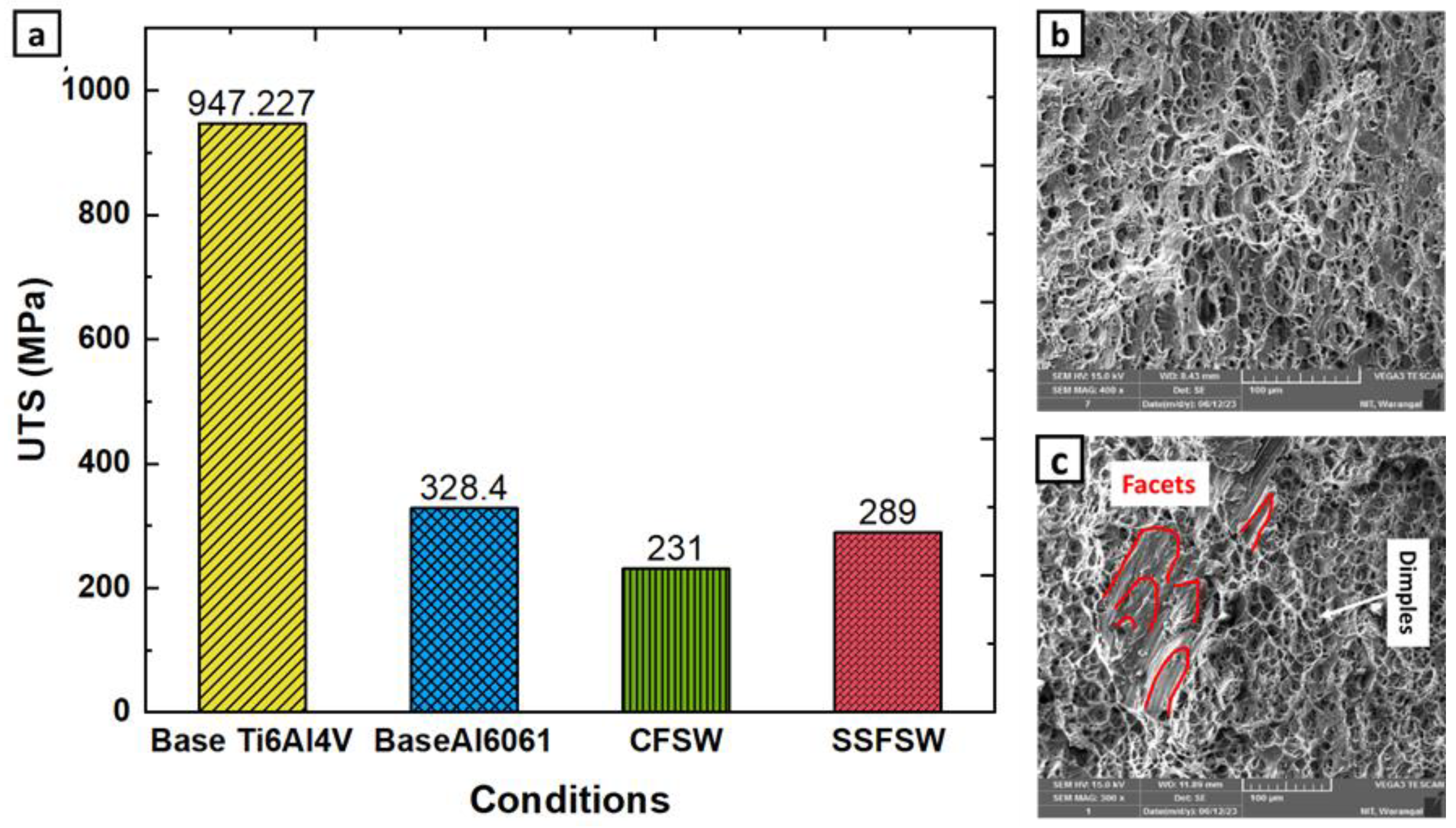
3.4. Cross Tensile Testing and Fracture Mechanism

Figure 10a illustrates the tensile strength outcomes of joints across different conditions and base materials. The peak tensile strength recorded for SSFSW was approximately 289 MPa, marking a 20.2% improvement over CFSW, with an associated joint efficiency nearing 88%. Notably, both welding techniques failed at the Ti interface, suggesting that the weld nugget is stronger than the Ti interface. This behavior is primarily ascribed to the higher thermal input during CFSW, which promotes the diffusion and reaction between Ti and Al elements near the interface. Consequently, this results in a more substantial IMC layer, causing notable volumetric alterations and accumulating pronounced residual stresses.
Figure 10b,c further present the fracture characteristics of joints fabricated using CFSW and SSFSW methods. The fracture behavior of these joints is intricately influenced by factors such as microstructural features, IMC layer thickness, and the existence of defects like voids. Furthermore, the interplay among dissimilar materials at the joint interface significantly dictates the fracture resilience and resistance against crack progression. Even though the fracture is initiated at the Ti interface, residual Al alloy remnants on the Ti side signify robust bonding. Dimple patterns evident on the fracture surfaces of SSFSW joints, as depicted in Figure 10b, point to a typical ductile fracture mechanism. The presence of these dimples suggests that the failure predominantly occurs within the Al alloy. In contrast, the fracture surfaces of the CFSW joints showcase cleavage facets, as highlighted in Figure 10a, indicative of a brittle fracture nature. Nevertheless, the coexistence of dimples alongside these cleavage facets, as illustrated in Figure 10, suggests a combined ductile–brittle fracture mode.

3.5. Microhardness Distribution

The evaluation of hardness between CFSW and SSFSW is depicted in Figure 11. Indentations were strategically placed across the weld area, progressing from the advancing to the retracting side at intervals of 0.5 mm. The base materials showcased hardness levels of up to 110 HV and 345 HV, respectively. The welding regions did not surpass these values due to the integrated presence of IMCs and the dissolution effects observed in the Al6061 precipitates within the SZ [4]. In the welding process connecting Al to Ti, SZ encountered intensified heat, marked by a sharp thermal contrast on both sides of the weld zone. It is worth noting that while Al and its alloys exhibit thermal conductivities ranging from 88 to 251 W/m-K, Ti demonstrates a notably lower conductivity of 17 W/m-K. This specific thermal attribute of Ti likely acts as a thermal buffer. As a result, the accumulated heat in the SZ could trigger the dissolution and enlargement of Al6061 precipitates, subsequently impacting the microhardness. This behavior is consistent with documented observations of temperature-induced precipitate transformations in Al6061, especially beyond 200 °C. Additionally, microhardness readings near the Ti junction mirror the base Al6061 levels. This phenomenon may stem from the presence of Ti elements near this junction, where temperature-related disparities prompt the creation of specific dislocations and associated thermal stresses [11]. Such stresses at the interface deter plastic changes, thus elevating the hardness near the Ti boundary for both CFSW and SSFSW.
Peak hardness values in the SZ for CFSW and SSFSW stood at 89 HV and 85 HV, respectively, with the corresponding lower limits at 52 HV and 63 HV. Interestingly, the disparity in SSFSW was minimal versus CFSW. The Ti boundary exhibited distinct intermetallic features, registering top hardness values of 333 HV and 318 HV for CFSW and SSFSW, respectively. A marked hardness surge was evident during the shift from SZ to the Ti junction and was pinpointed at 5 mm and 3 mm for CFSW and SSFSW. This suggests a narrowed SZ due to the diminished frictional heating in SSFSW. While the elevated temperatures in CFSW influenced the transformation and enlargement of transitional precipitates, resulting in decreased hardness at the Al junction, SSFSW showcased a more consistent hardness profile. This uniformity in SSFSW hints at a more consistent microstructure within the SZ.

4. Conclusions

This study explores the efficacy of SSFSW for joining dissimilar Al to Ti materials, comparing it with CFSW. SSFSW demonstrated superior outcomes over CFSW, yielding stronger, more uniform joints with reduced material intermixing and a concise interlocking hook at the interface. One key factor contributing to this superiority is the lower welding peak temperature of SSFSW (512 °C) compared to CFSW (617 °C), which is attributed to the static shoulder and the subsequent reduction in frictional heat. The in-depth characterization of the interface using TEM and SAED affirmed the distinct and non-agglomerated evolution of Al3Ti and Al5Ti2 IMCs and increased the thickness of the IMC layer in the case of CFSW in comparison to SSFSW. Microstructural assessments unveiled DDRX and CDRX occurrences, with SZ showcasing equiaxed grains and Ti particles as nucleation sites for PSN. The interfaces displayed diverse textures, with distinct patterns in the heat-affected zone on the retreating side resembling Al6061 and the heat-affected zone on the advancing side representing Ti6Al4V. SSFSW exhibited an 88% joint efficiency, which is 20.2% higher than CFSW and primarily attributable to differences in the fracture mechanism. Notably, SSFSW exhibited only dimples, indicating a ductile fracture mode, while CFSW illustrated both ductile and brittle modes of fracture, resulting in lower mechanical properties. Both CFSW and SSFSW exhibited hardness values below the base materials due to intercalated IMCs and dynamic recrystallization.

Author Contributions

Conceptualization, S.A.S., K.K.M. and A.K. (Adepu Kumar); methodology, S.A.S.; Software, S.A.S.; validation S.A.S., A.K. (Amlan Kar), K.K.M. and A.K. (Adepu Kumar); formal analysis, S.A.S.; Investigation, S.A.S., K.K.M. and A.K. (Amlan Kar); Resources, A.K. (Adepu Kumar); data curation, K.K.M. and A.K. (Amlan Kar); writing—original draft preparation, S.A.S. and A.K. (Amlan Kar); writing—review and editing, S.A.S., A.K. (Amlan Kar) and K.K.M.; visualization, A.K. (Amlan Kar) and K.K.M.; supervision, K.K.M. and A.K. (Adepu Kumar); project administration, A.K. (Adepu Kumar); funding acquisition, A.K. (Adepu Kumar). All authors have read and agreed to the published version of the manuscript.

Funding

This research received no external funding.

Data Availability Statement

The data presented in this study are available on request from the corresponding author. The raw/processed data required to reproduce these findings cannot be shared at this time as these data also form part of an ongoing study.

Acknowledgments

We would like to thank Vijayaraghavan, PSG Institute of Advanced Studies, for helping with the TEM sample preparation and analysis. We would also like to thank Indradev Samajdar, IIT-Bombay, for providing the EBSD facility.

Conflicts of Interest

The authors declare no conflicts of interest.

References

  1. Möller, F.; Thomy, C.; Vollertsen, F. Joining of Titanium-Aluminium seat tracks for aircraft applications—System technology and joint properties. Weld. World 2012, 56, 108–114. [Google Scholar] [CrossRef]
  2. Beygi, R.; Galvão, I.; Akhavan-Safar, A.; Pouraliakbar, H.; Fallah, V.; da Silva, L.F.M. Effect of Alloying Elements on Intermetallic Formation during Friction Stir Welding of Dissimilar Metals: A Critical Review on Aluminum/Steel. Metals 2023, 13, 768. [Google Scholar] [CrossRef]
  3. El-Sayed, M.M.; Shash, A.; Abd-Rabou, M.; ElSherbiny, M.G. Welding and processing of metallic materials by using friction stir technique: A review. J. Adv. Join. Process. 2021, 3, 100059. [Google Scholar] [CrossRef]
  4. Kumar, N.; Yuan, W.; Mishra, R.S. Friction Stir Welding of Dissimilar Alloys and Materials. Frict. Stir Weld. Dissimilar Alloys Mater. 2015, 1–126. [Google Scholar] [CrossRef]
  5. Ivanov, A.; Chumaevskii, A.; Amirov, A.; Utyaganova, V.; Savchenko, N.; Rubtsov, V.; Tarasov, S. Features of Structure and Properties of Lap-Welded Joints of Aluminum Alloy Al–4Cu–1Mg with Titanium Alloy Ti–6Al–4V, Obtained by Friction Stir Welding. Metals 2023, 13, 1385. [Google Scholar] [CrossRef]
  6. Kim, Y.-C.; Fuji, A. Factors dominating joint characteristics in Ti–Al friction welds. Sci. Technol. Weld. Join. 2002, 7, 149–154. [Google Scholar] [CrossRef]
  7. Balos, S.; Zlatanovic, D.L.; Kulundzic, N.; Janjatovic, P.; Dramicanin, M.; Lanc, Z.; Hadzistevic, M.; Radisic, S.; Rajnovic, D.; Pecanac, M. Influence of Tool–Base Metal Interference on the Performance of an Aluminium–Magnesium Alloy Joined via Bobbin Tool Friction Stir Welding. Metals 2023, 13, 1215. [Google Scholar] [CrossRef]
  8. Song, Z.; Nakata, K.; Wu, A.; Liao, J.; Zhou, L. Influence of probe offset distance on interfacial microstructure and mechanical properties of friction stir butt welded joint of Ti6Al4V and A6061 dissimilar alloys. Mater. Des. 2014, 57, 269–278. [Google Scholar] [CrossRef]
  9. Li, W.; Fu, T.; Hütsch, L.; Hilgert, J.; Wang, F.; dos Santos, J.; Huber, N. Effects of tool rotational and welding speed on microstructure and mechanical properties of bobbin-tool friction-stir welded Mg AZ31. Mater. Des. 2014, 64, 714–720. [Google Scholar] [CrossRef]
  10. Yang, H.; Zhao, H.; Xu, X.; Zhou, L.; Zhao, H.; Liu, H. Effect of Stirring Pin Rotation Speed on Microstructure and Mechanical Properties of 2A14-T4 Alloy T-Joints Produced by Stationary Shoulder Friction Stir Welding. Materials 2021, 14, 1938. [Google Scholar] [CrossRef]
  11. Chen, K.; Liu, X.; Ni, J. A review of friction stir–based processes for joining dissimilar materials. Int. J. Adv. Manuf. Technol. 2019, 104, 1709–1731. [Google Scholar] [CrossRef]
  12. Chen, Y.; Nakata, K. Microstructural characterization and mechanical properties in friction stir welding of aluminum and titanium dissimilar alloys. Mater. Des. 2009, 30, 469–474. [Google Scholar] [CrossRef]
  13. Wu, A.; Song, Z.; Nakata, K.; Liao, J. Defects and the properties of the dissimilar materials FSW joints of titanium alloy TC4 with aluminum alloy 6061. In Proceedings of the 1st International Joint Symposium on Joining and Welding, Osaka, Japan, 6–8 November 2013; pp. 243–248. [Google Scholar] [CrossRef]
  14. Li, B.; Zhang, Z.; Shen, Y.; Hu, W.; Luo, L. Dissimilar friction stir welding of Ti–6Al–4V alloy and aluminum alloy employing a modified butt joint configuration: Influences of process variables on the weld interfaces and tensile properties. Mater. Des. 2014, 53, 838–848. [Google Scholar] [CrossRef]
  15. Ahmed, M.M.Z.; Seleman, M.M.E.-S.; Fydrych, D.; Çam, G. Friction Stir Welding of Aluminum in the Aerospace Industry: The Current Progress and State-of-the-Art Review. Materials 2023, 16, 2971. [Google Scholar] [CrossRef]
  16. Kar, A.; Suwas, S.; Kailas, S.V. Two-pass friction stir welding of aluminum alloy to titanium alloy: A simultaneous improvement in mechanical properties. Mater. Sci. Eng. A 2018, 733, 199–210. [Google Scholar] [CrossRef]
  17. Kar, A.; Alam, Z. Solid State Additive Manufacturing, Solid State Additive Manufacturing; Taylor & Francis Ltd.: London, UK, 2023. [Google Scholar] [CrossRef]
  18. Ji, H.; Deng, Y.; Xu, H.; Lin, S.; Wang, W.; Dong, H. The mechanism of rotational and non-rotational shoulder affecting the microstructure and mechanical properties of Al-Mg-Si alloy friction stir welded joint. Mater. Des. 2020, 192, 108729. [Google Scholar] [CrossRef]
  19. Barbini, A.; Carstensen, J.; dos Santos, J.F. Influence of a non-rotating shoulder on heat generation, microstructure and mechanical properties of dissimilar AA2024/AA7050 FSW joints. J. Mater. Sci. Technol. 2018, 34, 119–127. [Google Scholar] [CrossRef]
  20. You, J.; Zhao, Y.; Dong, C.; Miao, S.; Liu, Z.; Liu, L.; Su, Y. Microstructural evolution and mechanical properties of the Al–Cu dissimilar joint enhanced by stationary-dynamic shoulder friction stir welding. J. Mater. Process. Technol. 2022, 300, 117402. [Google Scholar] [CrossRef]
  21. Sundar, A.S.; Kar, A.; Mugada, K.K.; Kumar, A. Enhancement of microstructure, micro-texture, and mechanical properties of Al6061 friction stir welds using the developed static shoulder welding tool. Mater. Charact. 2023, 203, 113148. [Google Scholar] [CrossRef]
  22. Ji, S.M.; Jang, S.M.; Lee, Y.S.; Kwak, H.M.; Choi, J.M.; Joun, M.S. Characterization of Ti-6Al-4V alloy in the temperature range of warm metal forming and fracture analysis of the warm capping process. J. Mater. Res. Technol. 2022, 18, 1590–1606. [Google Scholar] [CrossRef]
  23. Ranc, N.; Taravella, L.; Pina, V.; Herve, P. Temperature field measurement in titanium alloy during high strain rate loading—Adiabatic shear bands phenomenon. Mech. Mater. 2008, 40, 255–270. [Google Scholar] [CrossRef]
  24. Kailas, S.V.; Prasad, Y.V.R.K.; Biswas, S.K. Flow Instabilities and Fracture in Ti-6AI-4V Deformed in Compression at 298 K to 673 K. Metall. Mater. Trans. A 1994, 25, 2173–2179. [Google Scholar] [CrossRef]
  25. Jagadeesha, C. Flow analysis of materials in friction stir welding. J. Mech. Behav. Mater. 2018, 27, 20180020. [Google Scholar] [CrossRef]
  26. Zhao, Y.; You, J.; Qin, J.; Dong, C.; Liu, L.; Liu, Z.; Miao, S. Stationary shoulder friction stir welding of Al–Cu dissimilar materials and its mechanism for improving the microstructures and mechanical properties of joint. Mater. Sci. Eng. A 2022, 837, 142754. [Google Scholar] [CrossRef]
  27. Lee, I.; Hsu, C.; Chen, C.; Ho, N.; Kao, P. Particle-reinforced aluminum matrix composites produced from powder mixtures via friction stir processing. Compos. Sci. Technol. 2011, 71, 693–698. [Google Scholar] [CrossRef]
  28. Mishra, R.S.; Haridas, R.S.; Agrawal, P. Friction stir-based additive manufacturing. Sci. Technol. Weld. Join. 2022, 27, 141–165. [Google Scholar] [CrossRef]
  29. Gangwar, K.; Ramulu, M. Friction stir welding of titanium alloys: A review. Mater. Des. 2018, 141, 230–255. [Google Scholar] [CrossRef]
  30. Beygi, R.; Talkhabi, A.A.; Mehrizi, M.Z.; Marques, E.A.S.; Carbas, R.J.C.; da Silva, L.F.M. A Novel Lap-Butt Joint Design for FSW of Aluminum to Steel in Tee-Configuration: Joining Mechanism, Intermetallic Formation, and Fracture Behavior. Metals 2023, 13, 1027. [Google Scholar] [CrossRef]
  31. Zhang, Q.; Xiao, B.; Ma, Z. Mechanically activated effect of friction stir processing in Al–Ti reaction. Mater. Chem. Phys. 2013, 139, 596–602. [Google Scholar] [CrossRef]
  32. Liu, F.C.; Hovanski, Y.; Miles, M.P.; Sorensen, C.D.; Nelson, T.W. A review of friction stir welding of steels: Tool, material flow, microstructure, and properties. J. Mater. Sci. Technol. 2018, 34, 39–57. [Google Scholar] [CrossRef]
  33. A, S.S.; Mugada, K.K.; Kumar, A. Microstructural Evolution, Intermetallic Formation, and Mechanical Performance of Dissimilar Al6061–Ti6Al4V Static Shoulder Friction Stir Welds. Adv. Eng. Mater. 2023, 25, 2300973. [Google Scholar] [CrossRef]
  34. Zhao, C.; Li, S.; Wang, B.; Wang, N.; Zhang, Q.; Sun, Y.; Wang, L.; Guan, S. Microstructure and Mechanical Properties of Friction Stir Welded DP1180 Steel Plates. Metals 2023, 13, 1164. [Google Scholar] [CrossRef]
  35. Gong, F.; Feng, G.; Wang, Y.; Lan, S.; Zhang, J.; Wang, C.; Zhao, J.; Yang, Q.; Wang, Z. The Effect of Fe Content on the Microstructure and Tensile Properties of Friction-Stir-Welded Joints in Recycled Cast Aluminum Alloy. Materials 2024, 17, 64. [Google Scholar] [CrossRef] [PubMed]
  36. A, S.S.; Kumar, A.; Mugada, K.K. Investigation of material flow, microstructure evolution, and texture development in dissimilar friction stir welding of Al6061 to Ti6Al4V. Mater. Today Commun. 2022, 33, 104424. [Google Scholar] [CrossRef]
Figure 1. (a) Grain boundary character distribution map of as-received Al6061-T6 and (b) EBSD phase map of Ti6Al4V.
Metals 14 00128 g001
Figure 2. (a) Joint configuration indication of AS and RS sides, (b) joint configuration for CFSW and (c) joint configuration for SSFSW.
Metals 14 00128 g002
Figure 3. Temperature profiles observed during the joining process (a) CFSW and (b) SSFSW.
Metals 14 00128 g003
Figure 4. Optical macro and micrographs indicate the weld cross section and adiabatic shear band formation during (a) CFSW and (b) SSFSW [33].
Metals 14 00128 g004
Figure 5. SEM micrographs at the interface showing the morphology of the Ti particles formed during the welding process with (a) CFSW and (b) SSFSW.
Metals 14 00128 g005
Figure 6. Inverse pole figure map at the interface of (a) CFSW and (b) SSFSW.
Metals 14 00128 g006
Figure 7. KAM maps at the interface of (a) CFSW [36] and (b) SSFSW [33].
Metals 14 00128 g007
Figure 8. GOS maps at the interface of (a) CFSW [36] and (b) SSFSW [33].
Metals 14 00128 g008
Figure 9. HR-TEM images at the interface of (a) CFSW (b). SSFSW and XRD patterns obtained at the interface of (c) CFSW and (d) SSFSW.
Metals 14 00128 g009
Figure 10. (a) Tensile performance of the joints in terms of UTS at various conditions, (b) fracture surface of SSFSW joints, and (c) fracture surface of CFSW joints.
Metals 14 00128 g010
Figure 11. Microhardness distribution across the weldment of both SSFSW and CFSW.
Metals 14 00128 g011
Table 1. Chemical composition of the as-received base materials used in the present investigation.
MaterialChemical Composition (wt.%)
AA6061-T6AlCuFeMnSiZnMgCrTi
Bal0.270.290.070.630.011.000.170.02
Ti-6Al-4VTiAlVCONFe--
Bal6.144.29<0.10<0.20<0.05<0.3--
Table 2. Process conditions used in this study.
Process ConditionsCFSWSSFSW
Spindle speed (mm/rev)12001400
Travel speed (mm/min)4545
Tool offset (on Al side)3 mm3 mm
Tool tilt (°)1.50
Disclaimer/Publisher’s Note: The statements, opinions and data contained in all publications are solely those of the individual author(s) and contributor(s) and not of MDPI and/or the editor(s). MDPI and/or the editor(s) disclaim responsibility for any injury to people or property resulting from any ideas, methods, instructions or products referred to in the content.

