Abstract
At present, blast furnace (BF) ironmaking is still the main process for producing hot metal in China and around the world. Under the constraint of the global goal of “double carbon”, it is urgent to carry out hydrogen metallurgical innovation for the existing BF ironmaking process with higher carbon emissions. In recent years, BF technology with hydrogen enrichment and pure oxygen has made some progress, effectively reducing carbon emissions of hot metal per tons, but it is still unable to break through the technical bottleneck of emission reduction of more than 30%. In view of this, the authors put forward an ironmaking technology of a reduction smelting furnace (RSF) that is hydrogen-rich and utilizes pure oxygen and carbon recycle (Hy-O-CR), which breaks through the technical defect of traditional BF emission reduction of less than 30% by reshaping the furnace. Firstly, the construction process of the mass and energy balance model for two main unit modules in the new process (RSF with Hy-O-CR and top gas cycle) is introduced, and then the parameter optimization under specific scenario conditions is analyzed, and the influence mechanism of several key variables on the parameters in the furnace is obtained. Finally, the emission of CO2 in the whole process is explored in the case of two typical operating parameters. The results show that after using CCUS technology, the minimum value of direct CO2 emission is 215.93 kg/tHM, which is as high as 84.58% compared with the traditional BF process. Even if the removed CO2 is counted in carbon emissions, the minimum value of direct or indirect carbon emissions is 729.85 kg/tHM, and the proportion of emission reduction can reach 47.87%. The research results show that the reconstruction of Hy-O-CR technology can change the ratio of direct reduction and indirect reduction, which greatly breaks through the emission limit of the traditional BF and provides a new reference for hydrogen metallurgy technology and a basis for further study of the optimization of RSF size.
1. Introduction
Climate change is an urgent and formidable challenge facing human society today. Carbon dioxide (CO2), as an inevitable outcome of industrial society modernization, has caused a serious greenhouse effect; therefore, reducing carbon-based gas emissions has become a global goal. In September 2020, China’s president Xi Jinping proposed the “dual carbon” strategy at the 75th United Nations General Assembly, which aims to reach the peak of CO2 emissions before 2030 and achieve carbon neutrality before 2060 [1,2]. At present, the carbon-emitting industries of China are making efforts to develop decarbonization technologies, aiming to achieve carbon reduction transformation before the deadline set by the “dual carbon” targets. In this regard, the steel industry consumes approximately 13% of the national energy, while its carbon emissions account for around 15% of the total national emissions. Therefore, as a high-energy and high-emission sector, the steel industry urgently needs to undergo green and low-carbon transformation [3,4,5].
The blast furnace (BF) and basic oxygen furnace (BOF) process is still the main process of iron and steel production in China, in which more than 90% of the CO2 emission and 70% of the energy consumption are from the BF ironmaking process (sintering, coking, and BF). The entire process relies on reducing gas CO generated by coke for the reduction of iron oxides, and the resulting CO2 is directly emitted into the atmosphere. Therefore, implementing low-carbon transformation in the BF ironmaking process becomes a key step in reducing emissions in the steel industry [6,7,8,9]. The traditional BF, due to its advantages such as high production capacity, efficiency, low cost, and mature technology, will remain the mainstream steel production process for a considerable period of time in the future. After extensive research, metallurgists believe that “hydrogen metallurgy”, which utilizes H2 for reduction, is the primary direction for green and low-carbon development in the steel industry. It is expected that the proportion of hydrogen metallurgy will significantly increase year by year before 2060, becoming the mainstream process for reducing CO2 emissions [10,11]. Currently, many steel companies both domestically and internationally have made arrangements for hydrogen metallurgy, forming two feasible technical pathways: the short-process route of green hydrogen direct reduction with an electric arc furnace (EAF) and the long-process route of conventional BF reconstitution with hydrogen. Among them, the EAF process utilizing scrap steel or direct reducing iron (DRI) produced by hydrogen-based process as raw materials seems to be the most mature technology route to date, capable of reducing 95% of CO2 emissions. However, it is limited by scarce high-grade iron ore resources [12]. Considering the existing stock of BFs, it is anticipated that BF ironmaking will remain the primary ironmaking method in China in the short term. The hydrogen-rich ironmaking process in BFs has become more mature through continuous research, but there are significant differences between hydrogen-based and carbon-based gas reduction conditions. The hydrogen content in BFs remains at a low level, not exceeding 15%, greatly limiting the extent of CO2 emission reduction in BFs [11]. Exploring new methods of a high proportion of hydrogen to break through the CO2 emission limit requires technical reconstruction of the hydrogen-rich process and proposing new plans to provide theoretical and technical support for achieving the ultimate emission reduction in ironmaking.
Northeastern University has studied the key factors limiting emissions reduction in BFs and proposed a new ironmaking process of a reduction smelting furnace (RSF) that is hydrogen-rich and utilizes pure oxygen and carbon recycle (Hy-O-CR) [13]. They have also developed a mass–energy balance model for the new process in a previously published paper of Ref. [14]. By upgrading technologies such as injecting high-temperature reducing gas through the upper shaft tuyere and cooperating to control the gas distribution ratio between the shaft zone and the hearth zone, the technical bottleneck that the metallization rate in the upper part of the traditional BF is less than 70% has been solved. The two technologies of decarbonization of the top gas and hydrogen production by electrolysis of water are reconstructed to form a new technology of hydrogen-rich self-circulation of decarbonized gas. This technology involves decarbonized gas and green hydrogen being mixed, heated, and injected into RSF through a specific tuyere structure, which is a new technique that can significantly reduce carbon emissions in the ironmaking process.
The process of RSF with Hy-O-CR is a transformation and upgrade based on processes such as Fink [15], NKK [16], ULCOS top gas recycling blast furnace process [17], and shaft injection blast furnace [18,19,20]. The RSF process of full oxygen injection instead of the BF process with hot air injection can avoid the problem of nitrogen (N2) accumulation in the top gas circulation process cycle. The oxygen blast furnace (OBF) process often encounters the problem of excessive cooling in the upper zone [21,22]. Although injecting a high proportion of hydrogen-based gas from the shaft tuyere can significantly reduce carbon emissions, the endothermic reaction during the reduction with hydrogen-based gas exacerbates this problem [23]. Mehdi [24] addressed the issue of insufficient heat in the upper zone by adding auxiliary fuel combustion to release heat. Additionally, high-temperature reducing gases were injected into the furnace shaft to promote the reduction of FeO. The authors proposed a new process that also utilizes the injecting of a high-proportion hydrogen-based gas into the furnace shaft to achieve maximum emission reduction. The issue of insufficient heat in the upper zone was solved by excess high-temperature gas being injected into the furnace shaft, which significantly increased the metallization rate in the upper zone and minimized direct reduction in the lower zone. The heat generated from the combustion of auxiliary fuel sources (such as natural gas, coke oven gas, coal or coke, etc.) was sufficient to meet its internal heat consumption for direct reduction in the lower zone, and the excess gas flowed upstream and carried the waste heat from the lower zone to the upper furnace shaft area. This inevitably led to a decrease in the gas utilization rate inside the furnace, but the gas generated from the combustion of auxiliary fuel can be fully utilized by means of the top gas circulation, which improves the overall gas utilization.
The top gas circulation model is a sub-module of the new RSF process. It is a new technology for hydrogen-rich recycling of the top gas treated by CO2 removal equipment. The main components of the circulating gas are CO and H2. Considering the carburization phenomenon of the mixture of CO and H2 in the heating process, the circulating gas process has been modified and upgraded in order to better fit the new process. Mapelli C [25] researched the future scenarios for reducing emissions and consumption in the Italian steelmaking industry. The amount of CO2 emissions, water and electricity consumption, and soil exploitation of the main steel production routes (integrated cycle, scrap recycling, and direct reduction) were analyzed applying three possible future scenarios: use of carbon capture and storage (CCS); use of green hydrogen in substitution of natural gas; and use of biomethane. Foo S Y [26] proposed that introducing a certain amount of CO2 can suppress the carburization reaction of CO and H2 in the furnace. Therefore, in this model, the CO2 removal rate of the top gas is not 100%, and the remaining CO2 is introduced into the furnace along with CO and H2. This not only inhibits the carburization phenomenon of the circulating gas but also reduces the decarburization cost. By combining CO2 capture, utilization, and storage technologies (CCUS), the overall process achieves maximum emission reduction. In addition, in order to fully utilize the chemical heat of the top gas, a certain proportion of the top gas is used as the combustion gas source to heat and elevate the temperature of the circulating reducing gas injected into the furnace shaft. The electrolytic water device is used to supply the required H2 for the hydrogen-rich process of reducing gas, and the byproduct oxygen (O2) can also serve as a direct source of O2 injected through the lower tuyere into the RSF [27]. Although the power consumption and cost of the process flow after using electrolytic water for hydrogen production are higher compared to traditional BFs, with the reduction of the cost of hydrogen production, the optimization of the process, and the development of CCUS technology in the future, the new process will have a very broad development prospect in the future low-carbon era.
2. Model of RSF with Hy-O-CR
The schematic diagram of the new process of RSF with Hy-O-CR is shown in Figure 1. The top gas produced in the RSF is purified by a dust collector and then divided into two parts, of which a small part of the gas is used as a combustion gas source for combustion and heating, and most of the gas goes into the dryer for H2O removal and the CO2 separator for CO2 separation. The removed H2O can be recycled and used as a water source for the electrolytic water process. The extracted CO2 enters a CO2 storage tank for enhanced oil recovery or chemical raw materials. The resulting reducing gas is divided into two parts for further treatment, a small part of which is directly stored in the gas tank without heating as a backup gas source. In addition, most of the reducing gas (CO, H2, and a small amount of CO2) is mixed with a certain amount of hydrogen, enters into the heating exchanger, and is heated to form high-temperature (>900 °C) reducing gas, which is injected into the RSF from the furnace shaft tuyere to achieve decarbonization reduction gas recycling. The reason for not fully removing CO2 is that the inclusion of a certain amount of CO2 effectively prevents carburization reactions during the heating process [28,29]. The electrolytic water device supplies sufficient H2, which is also supplemented into the heat exchanger. The byproduct O2 can be injected into the lower tuyere for full oxygen injecting.
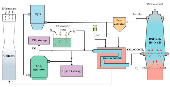
Figure 1.
Schematic diagram of the new process of RSF with Hy-O-CR.
The RSF is a physical and chemical reaction process conducted in a closed and complex system, and it is impossible to obtain key process parameters inside the furnace through measurements. Therefore, constructing a mathematical model for process calculation can quantitatively obtain the changes in mass and energy inside the RSF, providing data support for subsequent parameter optimization, capacity expansion, or increasing the CO2 emission reduction limit. A reaction model of RSF was established based on the principle of mass and energy conservation, with the production per ton of hot metal (HM or molten iron) as the reference. The model obtained the mass of raw materials consumed per ton of HM, the volume and composition of reducing gas, the mass and composition of corresponding by-products such as slag, and the volume and composition of the top gas.
The process of establishing the mathematical model and its calculation process for the RSF will be described in the following section. The established mathematical model can be used to analyze and determine the volume of reducing gas and top gas required per ton of HM in the RSF, providing input and output conditions for the top gas circulation model and facilitating the selection of subsequent decarburization equipment capacity on-site.
2.1. Boundary Conditions of RSF with Hy-O-CR Model
The compositions of the iron-containing raw materials, namely, coke and flux in this paper, are listed in Table 1, Table 2 and Table 3. The sulfur and silicon compositions in the hot metal are set according to conventional values, as shown in Table 4. The other components in the HM are obtained based on empirical formulas. The formula for the carbon content is [C] = 1.34 + 2.54 × 10⁻³ × THM − 0.35[P] − 0.30[Si] − 0.54[S] + 0.04[Mn], where THM represents the temperature of hot metal in °C and the element symbols ([P], [Si], [S], [Mn]) represent their content in hot metal in %.

Table 1.
Composition of iron ore raw materials (mass fraction), %.
Table 2.
Composition of coke (mass fraction), %.
Table 3.
Composition of flux (mass fraction), %.
Table 4.
Composition of hot metal (mass fraction), %.
In addition to the boundary conditions above, referring to the relevant previous work [30,31,32,33,34,35,36], the process parameters are assumed based on the calculation results of a hydrogen-rich blast furnace, hydrogen-based shaft furnace, and so on. The following assumptions are used in the model:
- (1)
- Within the RSF, a gas temperature of 1000 °C is used as the boundary between the upper and lower zone, which are divided into the upper low-temperature reduction zone and the lower high-temperature smelting zone, assuming that the boundary temperature for the solid burden entering the lower high-temperature zone is 950 °C, and the boundary temperature for gas entering the upper low-temperature zone is 1000 °C.
- (2)
- Sulfur in the RSF goes into the top gas, hot metal, and slag. The distribution ratio of sulfur in the top gas (ωs_top) is 5% [30], the content of sulfur in the hot metal is 0.025%, and the others enter the slag.
- (3)
- The methane production ratio (φCH4) is 1% of the total carbon consumption in the lower zone [31].
- (4)
- The temperature of the hot metal and slag are set to 1500 °C and 1550 °C, respectively.
- (5)
- In order to ensure the fluidity of the slag, the binary basicity (R2) of the slag is set to 1.15 [30,31].
- (6)
- According to the operation experience of the shaft furnace, the reduction potential (E) of the top gas is not less than 1.22 [32].
Under the constraints of the aforementioned boundary and assumption conditions, the model investigated the impact of different top gas temperatures (Ttop_gas), metallization rates [33,34] (MR) in the bottom of the shaft, water–gas reaction rates [35,36] (φwater_gas), and composition (φCO_redu) and temperature (Tredu) of the reducing gas on key parameters of the RSF process.
2.2. Mass Balance
According to the corresponding parameter settings under different operating conditions, based on the production of 1 ton of hot metal, the initial value of the coke mass is set. Through element mass balance in the RSF, the consumption of raw materials, mass of the slag, and composition and flow rate of gas in different parts of the RSF, as well as the flow rate of hot air can be obtained. The input parameters of the overall model for the RSF include iron ore, coke, flux, and the composition of reducing gas entering the RSF shaft tuyere. The output parameters include the consumption of raw materials (ore, flux, and gas circulation) for the production of 1 ton of hot metal, as well as the mass and composition of the top gas and slag produced. Mass balance calculations can quantitatively analyze the impact of operational parameters on the mass of coke consumption and important indicators, such as CO2 emissions, while providing basic data for heat balance calculations. The coke consumption can be obtained through iterative calculations based on heat balance.
2.2.1. Mass of Iron Ore Consumption
Through the Fe element balance equation corresponding to the input material and the output product, it is possible to derive the consumption of iron ore. The main input sources of Fe element are iron ore, with a small amount or partial contribution from coke and flux; the output form of the Fe element is mainly in the form of HM, with a small amount or partial distribution in the slag or the dust of the top gas. Taking the production of 1 ton of HM as a reference, the consumption of iron ore, denoted as more, is calculated according to Formula (1).
where i represents HM, slag, and dust; j represents coke and flux; mFe_i and mFe_j represent the mass of Fe in the HM, slag, dust, coke, and flux, kg/tHM; ωFe_ore represents the mass fraction of Fe in mixed iron ore, %; and mFe2O3_coke represents the mass of Fe2O3 in coke, kg/tHM.
2.2.2. Mass of Flux Consumption
From the element conservation of oxide CaO and SiO2 and the binary basicity equation of slag, it is possible to derive the amount of flux consumption. Slag is a byproduct of the ironmaking process, and its basicity affects its fluidity, thereby affecting the smooth operation of the RSF. The basicity of the slag in this model is represented by the binary basicity (R2). The CaO and SiO2 in the slag mainly come from the flux, with a small amount coming from coke and raw materials. A small amount of SiO2 in the output product is reduced by direct reduction and is distributed in hot metal in the form of [Si]. The mass of the flux can be derived according to Formula (3).
where i represents ore, coke, and flux; mi represents the mass of the iron ore, coke, and flux, kg/tHM; ωCaO_i and ωSiO2_i represent the mass fraction of CaO and SiO2 in the input burden of iron ore, coke, and flux, %; and ωSi_HM represents the mass fraction of Si in the hot metal, %.
2.3. Energy Balance
Taking the gas temperature in the shaft at 1000 °C as the limiting condition, the reduction zone is divided into the upper low-temperature reduction zone and the lower high-temperature reduction zone, and the energy balance of the high-temperature zone and the low-temperature zone are calculated respectively. By establishing the energy balance equation for the lower high-temperature zone, the consumption of coke can be solved to meet the minimum heat requirements for direct reduction in the lower zone and the heat required for slag-iron melting. Through the establishment of the energy balance equation in the upper low-temperature region, the amount of reducing gas and the utilization rate of gas needed in the iron ore reduction process are calculated according to the thermodynamic equilibrium constant, and through the double constraints of heat demand and minimum reduction potential requirements, the amount of shaft reduction gas that needs to be added in the reduction process can be determined. It should be noted that the decisive temperature of the thermodynamic equilibrium constant is 950 °C for the solid burden entering the lower high-temperature zone. By using the step-by-step reduction method, the reduction zone in the upper part of RSF is divided into three stages, and the main chemical reactions and heat changes are shown in Table 5.
Table 5.
Chemical equation and ΔH (kJ/mol).
From Table 5, it can be seen that in the reduction process of iron oxides by H2 in the upper zone, except for the reaction 3Fe2O3 + H2 = 2Fe3O4 + H2O, the other reactions are endothermic. If the proportion of H2 is too high, it will inevitably cause a problem of insufficient heat in the upper zone. Therefore, the authors used the combustion of auxiliary fuel (coke was used in the basic case) in the lower zone to solve this problem, and the supplementary combustion fuel only provides heat. The minimum consumption of coke was obtained by solving the energy balance equation of the high-temperature zone. Under the double constraints of heat balance and minimum reduction potential of the top gas (E > 1.22) [30], the total amount of reducing gas injected into the shaft tuyere that meets the conditions above was calculated for the upper low-temperature zone. Finally, the composition and flow rate of the top gas were obtained through the C-H-O element balance.
2.3.1. Calculation of Coke Ratio
In order to compensate for the insufficient heat in the upper zone during reduction, the process adopts two optimization methods: injecting high-temperature reducing gas into the shaft tuyere and utilizing the high-temperature gas generated by coke combustion in the lower zone to achieve counterflow heat transfer. The heat matching issue between the upper and lower zones is achieved by adjusting two key operational parameters: the coke ratio and reducing gas volume. The coke ratio, represented by mcoke, is divided into two parts: the mass of coke involved in the direct reduction process (mredu_coke), the mass of coke for hot metal carburization, and the mass of coke used for combustion heating (mburn_coke). The mass of coke is obtained by heat balance of the high-temperature zone. The heat input terms (Qin_low) of the high-temperature zone include the heat generated by coke combustion at the tuyere (Qburn_coke), the sensible heat brought into the lower zone by high-temperature solid materials of coke (Qcoke) and DRI (QDRI). The heat output terms (Qout_low) include the heat carried away by hot metal (QHM) and slag (Qslag) leaving the lower zone, the heat carried away by gas rising into the upper zone (Qgas_low), the heat consumed by the direct reduction of elements such as Fe, Si, and Mn in the lower zone (Qredu_low), and the heat loss in the lower zone (Qloss_low).
The mass of coke consumption (mcoke) is calculated according to Formulas (4)–(6).
where Qburn_coke represents the combustion heat of coke in high temperature zone, MJ/tHM; mloss_O_up represents the losing O amount of iron ore in the upper zone after indirect reduction, kg/tHM; and qDRI represents the specific heat capacity of DRI or sponge iron in the high-temperature (950 °C) zone, MJ/kg.
2.3.2. Calculation of Reducing Gas Volume
The upper zone of the RSF needs to satisfy two constraints, namely, the heat balance and minimum reduction potential of the top gas. The reasonable flow rate of the reducing gas is obtained under the two constraints above, in which the composition of the reducing gas is CO:H2 = 3:7 in the basic case. The following points need to be explained. In view of the successful experience of MIDREX, the authors suggest that the CO:H2 of the reducing gas composition should be set to 3:7, which is only a reference case, and the effects of different components on the RSF process in the following part will be analyzed. The heat input terms (Qin_up) in the upper zone include the heat released by Fe2O3 through CO and H2 reduction (QCO_Fe2O3, QH2_Fe2O3), the heat released by FeO through CO reduction (QCO_FeO), the sensible heat of high-temperature reducing gases injected into the shaft tuyere (Qgas_shaft), the heat released by the water–gas reaction (QH2O_CO), and the physical heat carried by the counterflow rising gas from the lower zone (Qgas_low). The heat output terms (Qout_up) in the upper zone include the heat absorbed by FeO through H2 reduction (QH2_FeO), the heat absorbed by Fe3O4 through CO and H2 reduction (QCO_Fe3O4, QH2_Fe3O4), the heat carried by coke and DRI entering the lower zone (Qcoke, QDRI), the heat carried away by the top gas (Qgas_top), the heat absorbed from carbonate decomposition (QCaCO3_MgCO3), and the heat loss in the upper zone (Qloss_up).
The required reducing gas volume is calculated by Formulas (7)–(9).
where i represents CO_Fe2O3, H2_Fe2O3, CO_FeO, and H2O_CO; j represents H2_FeO, CO_Fe3O4, H2_Fe3O4, CaCO3, and MgCO3; and VCO_top, VH2_top, VCO2_top, and VH2O_top represent the volume of CO, H2, CO2, and H2O, respectively, in the top gas, Nm3.
2.4. Calculation Flow Chart of the RSF Model
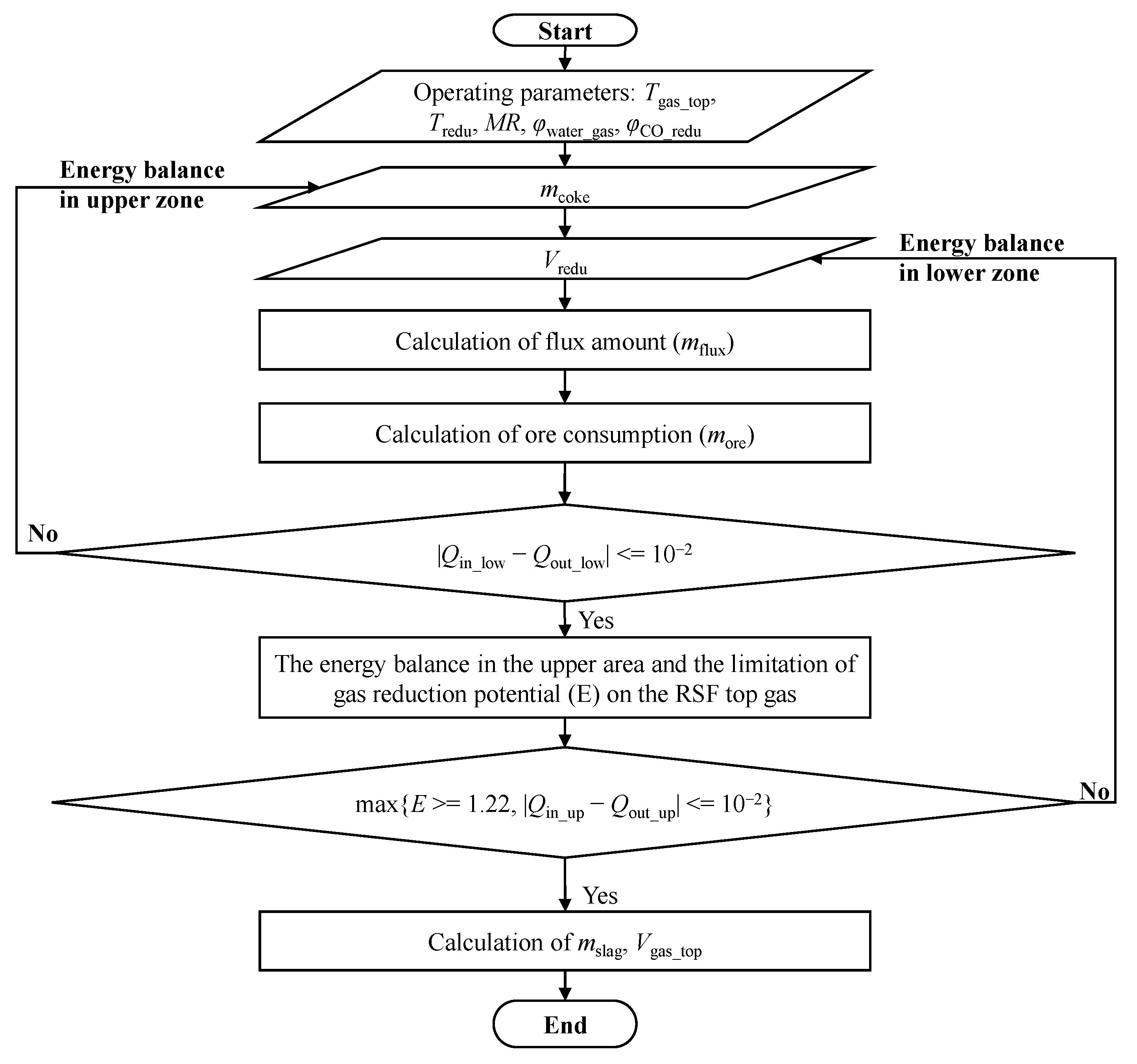
Under the same boundary conditions, the model studies the effects of process parameters such as the temperature of the top gas, MR, water–gas conversion rate, reducing gas temperature, and composition (the ratio of CO:H2). The program calculation flowchart is shown in Figure 2. According to the constraint conditions of the model, the results satisfying the process balance of the whole process under different operation parameters are calculated, and through iterative calculations, the results of the mass and heat balance for the low-temperature and high-temperature zones inside the RSF are obtained.
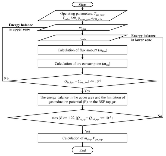
Figure 2.
Program calculation flow chart.
The steps of the program calculation process are as follows:
First of all, the mass of iron ore and flux is obtained by a mass balance equation and basicity equation. The iterative calculation is carried out under the constraints of the high-temperature zone heat balance, low-temperature zone heat balance, and the minimum reduction potential of the top gas, and the values of the operating variables, such as coke consumption and reducing gas volume injected from the shaft tuyere, are obtained.
Secondly, the mass and composition of the slag produced by the RSF are obtained by calculating the incoming material through the mass conservation of the element of the raw material.
Finally, under the limitation of the metallization rate and water–gas reaction ratio, the gas composition and volume of different stages of the process of iron ore reduction are deduced, and the calculation results are preserved in the form of the total volume of the top gas and the proportion of each component. In addition, the model can also obtain the oxygen consumption needed for combustion in the lower high-temperature area, which provides data support for the follow-up top gas cycle model.
3. Model of Top Gas Recycling
The carbon recycling of the top gas can reduce the consumption of fossil fuels and help to achieve carbon neutrality around the world as soon as possible. In the traditional BF ironmaking process, hot air is injected into the lower tuyere zone, resulting in a high concentration of N2 (vol. > 45%) in the top gas. The circulation of gas inevitably leads to N2 accumulation issues. Therefore, this study proposes a new ironmaking process reactor called the RSF, which adopts a fully oxygen injecting design to avoid or eliminate the N2 accumulation issues. The top gas is divided into two parts: one part is used as a combustion gas source for heating the decarburization gas, while the other part serves as a gas source for generating decarburization gas. As a gas source for producing decarburization gas, it needs to undergo purification treatment due to the presence of non-reducible gases (such as H2O and CO2) in its composition. The H2O and CO2 are removed through a dryer and a CO2 separator device (pressure swing adsorption unit), respectively. The removed H2O can be recycled as a water source of an electrolytic device, and the removed CO2 can be utilized as a gas source for oil recovery or as a raw material for chemical products. The remaining decarburization gas, which has a high reduction potential (vol. (CO + H2) > 95%), is reheated and re-injected into the furnace through a specific tuyere for recycling. The gas treatment process described above can maximize the use of gas resources and improve the overall energy efficiency of the process.
3.1. Boundary Conditions of Top Gas Recycling Model
The initial composition of the circulating gas source is obtained by real-time iterative updating of the top gas composition obtained from the RSF process calculation model. The following assumptions were made during the model establishment process.
- (1)
- The heat loss of the top gas is neglected when it is cleaned and recycled.
- (2)
- The dedusting rate of the dust collator is set at 100%, and the dewatering rate of the dryer is set at 100%.
- (3)
- The adsorption rate of CO2 separator is 95%, and it has no effect on the adsorption of other gas components.
- (4)
- The heat exchange rate of the heat exchanger is set at 60%.
3.2. Calculation of the Top Gas Recycling Model
In order to give full play to the reduction effect of decarbonized gas in the RSF, it is necessary to raise its temperature to 950 °C, which can be achieved by electric heating or combustion heat exchange. However, using electric heating would increase the overall energy consumption of the system. Therefore, this model uses the method of burning part of the top gas for heating in order to improve the thermal efficiency of the system. The amount of gas required for combustion is related to the heat required for raising the temperature of the decarburization gas and can be calculated using Equation (10).
where Vi_redu represents the volume of i component of the reducing gas, Nm3/tHM; i represents CO, CO2, or H2; qi represents the sensible heat per unit volume i at 950 °C, MJ/Nm3; ωj_top represents the molar amount of j, mol/tHM; j represents CO or H2; and Qj represents the heat released by the combustion of H2 or CO, MJ/mol.
4. Results and Discussion
The establishment of a comprehensive mathematical model enables the understanding of quantitative relationships between various parameter variables, facilitating the adjustment of input parameters to improve the operational performance indicators of the RSF. Under specific boundary conditions, this study utilizes the developed mathematical model to analyze in-depth the effects of different variables on key smelting parameters inside the RSF. These include the temperature and composition (CO:H2) of the decarburization circulating reducing gas injected from the RSF shaft tuyere, which impact process energy consumption and carbon emissions; the variation in the metallization rate of iron ore affecting the flow rate of decarburization circulating reducing gas and the coke ratio; and the influence of the water–gas reaction ratio parameters on the utilization rates of CO and H2 in the top gas. In addition, the carbon and hydrogen footprints can be clearly drawn through the model in this paper, which provides a direction for the further optimization of the process.
4.1. Effect of Decarbonization Reducing Gas on Process Energy Consumption and Carbon Emissions
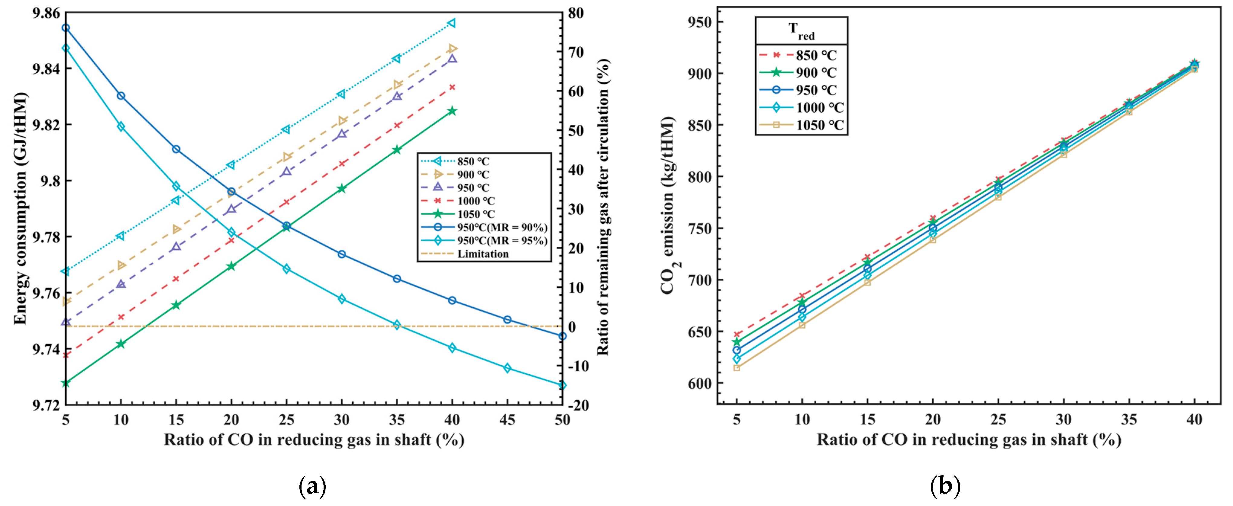
The composition and temperature of the reducing gas injected from the RSF shaft tuyere have a significant impact on the thermal balance inside the RSF and are also one of the key factors in optimizing the RSF with the Hy-O-CR process. The total energy consumption of the RSF can be obtained from the overall process heat balance model, which includes the carbon oxidation heat, high-temperature reducing gas sensible heat, hydrogen oxidation heat, methane generation heat, and slag formation heat. The model analyzes the effects of the composition (different CO ratios, φCO_redu) and temperature (Tredu) of the reducing gas on the total energy consumption and CO2 emissions inside the RSF, with the calculation results shown in Figure 3.
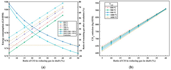
Figure 3.
The influence of φCO_redu and Tredu on energy consumption (a) and CO2 emissions (b).
In Figure 3a, it can be observed that as the CO ratio increases in the injected reducing gas (with a corresponding decrease of the H2 ratio), the heat released from carbon oxidation gradually increases, while the heat released from hydrogen oxidation decreases. The total amount of injected reducing gas decreases, resulting in a reduction in the sensible heat brought in by the high-temperature reducing gas, but the total energy consumption increases in the whole process. The research findings indicate that increasing the CO ratio in the injected reducing gas from 5% to 40% leads to a 1% increase in energy consumption, approximately 93.8 MJ/tHM. In other words, for every 1% increase in the CO ratio, energy consumption increases by 2.68 MJ/tHM. The results above are based on hydrogen production from clean energy power generation, which does not produce any carbon emissions. Therefore, the energy consumption of hydrogen production by electrolysis is not considered in the process above, so the influence of different hydrogen production technologies on energy consumption is also one of the restrictive factors to be considered in this new process in the future. Additionally, from Figure 3a, it can be observed that as the temperature of the injected reducing gas increases, there is a slight decrease in total energy consumption, which is due to the increase of sensible heat carried by the reducing gas and leads to the decrease of the amount of reducing gas. Under the condition of satisfying the reduction potential, it will inevitably lead to the increase of the CO utilization rate of the top gas, and then the total energy consumption will be reduced.
In addition, the comprehensive process model should also consider the proportion of residual gas after the circulation of the top gas, which is a crucial indicator for assessing the overall utilization efficiency of the new process. When the proportion of residual gas after circulation is equal to 0, it indicates that the high reduction potential gas formed after the top gas treatment is used in the cycle, which not only ensures the maximum utilization of the gas cycle, but also does not need external equipment for gas storage and supply. However, the metallization rate (MR)is one of the main factors affecting the process above, and the model analyzes the influence of the metallization rate on the circulating gas volume, as shown in Figure 3a. It can be seen in the figure that when the iron ore is moved down to the bottom of RSF shaft and the MR is 90%, the φCO_redu of the reducing gas at around 45% can meet the requirement for the complete utilization of the top gas circulation. While the MR is 95%, the φCO_redu of the reducing gas is approximately 35%, which can meet the requirement for the complete utilization of the top gas circulation.
At the same time, as the CO ratio of the injected reducing gas increases, the emission of CO2 also significantly increases, as shown in Figure 3b. The calculations of the model indicate that, while satisfying the constraints of thermal balance inside the RSF, for every 1% increase in the CO ratio of the reducing gas, the emission of CO2 increases by approximately 7.53 kg/tHM. The temperature of the injected reducing gas has a certain influence on CO2 emissions at low CO concentrations, but this influence diminishes as the CO concentration increases. This is because, with the increase in CO concentration, the effect of H2 becomes weaker, resulting in a weakened reduction in CO2 emissions.
Overall, it is currently difficult to simultaneously reduce energy costs and achieve low CO2 emissions. At present, this process has limited CO2 emissions as much as possible while considering cost control. However, with the reduction of energy costs and the development of “green hydrogen” technology in the future, there is potential for further optimization and adjustment of the process parameters to break through the upper limit of emission reduction and achieve even greater emission reductions.
4.2. Effect of MR on Decarbonization Reduction Gas and Coke Ratio
In traditional BFs, the MR has consistently remained below the upper limit of 70% (that is, the direct reduction degree by carbon is higher than 30%) as the burden materials descend to the furnace shaft. This is primarily due to the lower rate of the reduction agent CO compared to H2 (the proportion of H2 in BF is less than 5%). This new process employs the method of injecting reducing gas from the RSF shaft tuyere to achieve integrated technological upgrades, such as high temperature and high hydrogen enrichment in the RSF shaft. As a result, the MR in the upper zone can be increased to around 90%. The improvement in the MR in the upper zone inevitably reduces the demand for direct reduction processes in the lower zone, which can greatly reduce the demand for direct reduction heat, and then greatly reduce the coke demand for direct reduction in the lower region, so as to reduce the consumption of fossil energy. At the same time, it is necessary to increase the amount of reduction gas at the furnace body in order to meet the demand of indirect reduction in the upper region.
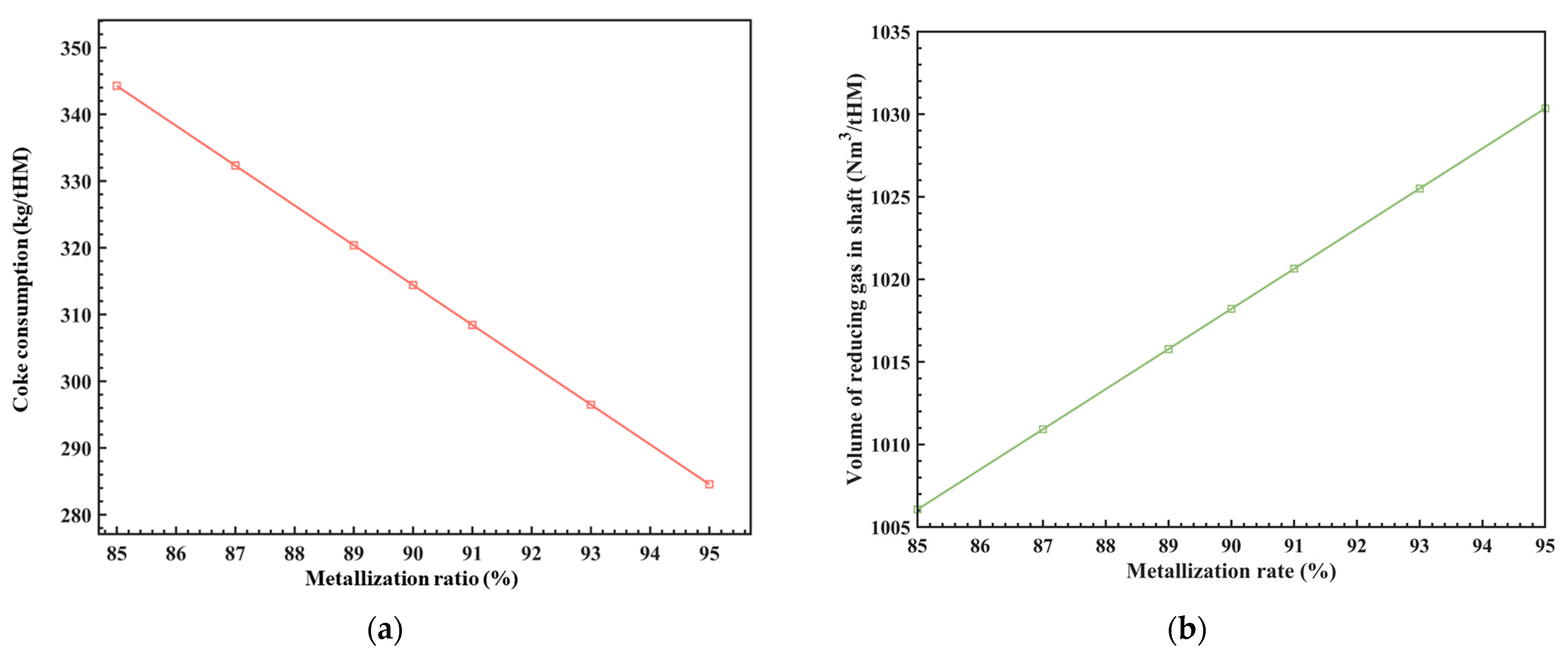
The MR is related to the coke ratio and the amount of reducing gas injected into the RSF shaft. Under the conditions of φCO_redu = 30%, Tredu = 950 °C, and φwater_gas = 30%, the relationship between these parameters was analyzed using the model above, and the results are shown in Figure 4. It can be seen that for every 1% increase in the MR of the iron ore at the RSF shaft, the consumption of coke (coke ratio) is reduced by approximately 5.95 kg/tHM, and the amount of reducing gas is increased by approximately 2.45 Nm3/tHM, which corresponds to a ratio of about 0.2%. These results provide a basis for adjusting the process parameters.
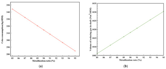
Figure 4.
The influence of MR on coke consumption (a) and the volume of shaft reducing gas (b).
As we all know, the MR of the iron ore at the RSF shaft is also related to parameters such as the composition, temperature, and flow rate of the reducing gas at the RSF shaft. The uniformity of the radial MR is also a key factor to consider. Currently, this model simplifies the analysis of the influence of different MR on process parameters. In future work, various dynamics will be incorporated to study the effects of these variables on the MR and the level of radial MR uniformity. This will provide references for the RSF size design.
4.3. Effect of Water–Gas Reaction Ratio on Gas Utilization Ratio
In the RSF, both CO and H2 are the main reducing agents involved in the reduction process of iron oxides. The gas utilization rate of CO or H2 represents the efficiency of gas utilization inside the furnace, which also represents the degree of reaction of the reducing gas inside the furnace. Previous in-depth research has been conducted on this topic. Japanese scholars [35,36,37,38,39] found that when the proportion of H2 in the BF is high, the product H2O in the reduction process from FeO to Fe will inevitably undergo a water–gas shift reaction with CO (H2O + CO = H2 + CO2) during the gas upward movement, and the higher the proportion of H2, the higher the proportion of the reaction with CO. It should be noted that the formula for calculating the utilization rate of CO and H2 used in this paper is the same as that in the previous literature [31,32,33], namely, the utilization of CO(ηCO) is equal to CO2/(CO + CO2), and the utilization of H2(ηH2) is equal to H2O/(H2 + H2O). In addition, the water–gas reaction ratio is equal to H2O**/H2O*, in which H2O* represents the generation amount of H2O in the reduction process from FeO to Fe by H2, and H2O** represents the consumption amount of H2O during the gas’s upward movement.
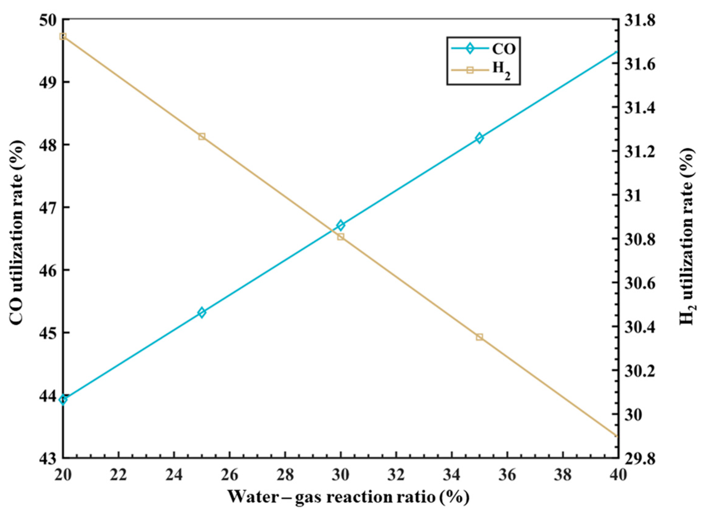
Based on the research above, this model introduces the variable of the proportion of the water–gas shift reaction with CO to consider the impact of different water–gas reaction ratios on the gas utilization rate inside the RSF. The results of the model calculation are shown in Figure 5. It can be observed that as the ratio of the water–gas shift reaction increases, the utilization rate of CO increases, while the utilization rate of H2 decreases. Specifically, for every 1% increase in the water–gas reaction ratio, the utilization rate of CO increases by approximately 0.27%, while the utilization rate of H2 decreases by approximately 0.01%. This is because the water–gas shift reaction (CO + H2O = CO2 + H2) proceeds in the forward direction, producing CO2 and H2 as products. A higher proportion of water–gas shift reaction results in a decrease in the proportion of CO and an increase in the proportion of H2 in the top gas, leading to an increase in the CO utilization rate and a decrease in the H2 utilization rate. However, it should be noted that in the actual process, H2 plays the role of a catalyst. Without the presence of H2, the desired high MR would not be achieved. Therefore, there is also an upper limit for the amount of H2, as excessive H2 would only lead to resource waste.
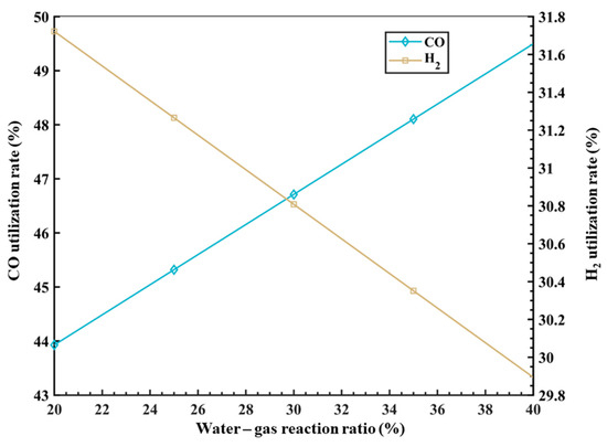
Figure 5.
The influence of φwater_gas on gas utilization rate.
4.4. Analysis of Carbon–Hydrogen Footprints
The reduced melting furnace process described in this article adopts a carbon–hydrogen dual reducing agent coupling method to reduce iron oxides in the furnace. Due to its excellent performance in the BF, coke or carbon-based gases are still extensively used in this model. Through mathematical modeling of different zones, a quantitative analysis can be conducted on the forms and footprints of carbon-containing substances at various inlet and outlet points in the RSF. The carbon footprint flow can provide a better analysis of the usage status of carbon-based materials and CO2 emissions, enabling a more accurate assessment of the new process in terms of carbon reduction requirements and national policies, in order to establish suitable operational systems. Additionally, a high proportion of hydrogen in the reducing gas of the RSF is the main driving force in the reduction process. By establishing the hydrogen footprint flow, the utilization status of hydrogen-based materials in the RSH can be clarified. In a relatively short period, due to the current technological limitations, there is a higher cost for hydrogen production. However, it is possible to lower the overall process cost by appropriately increasing the hydrogen recycling ratio and enhancing water reuse.
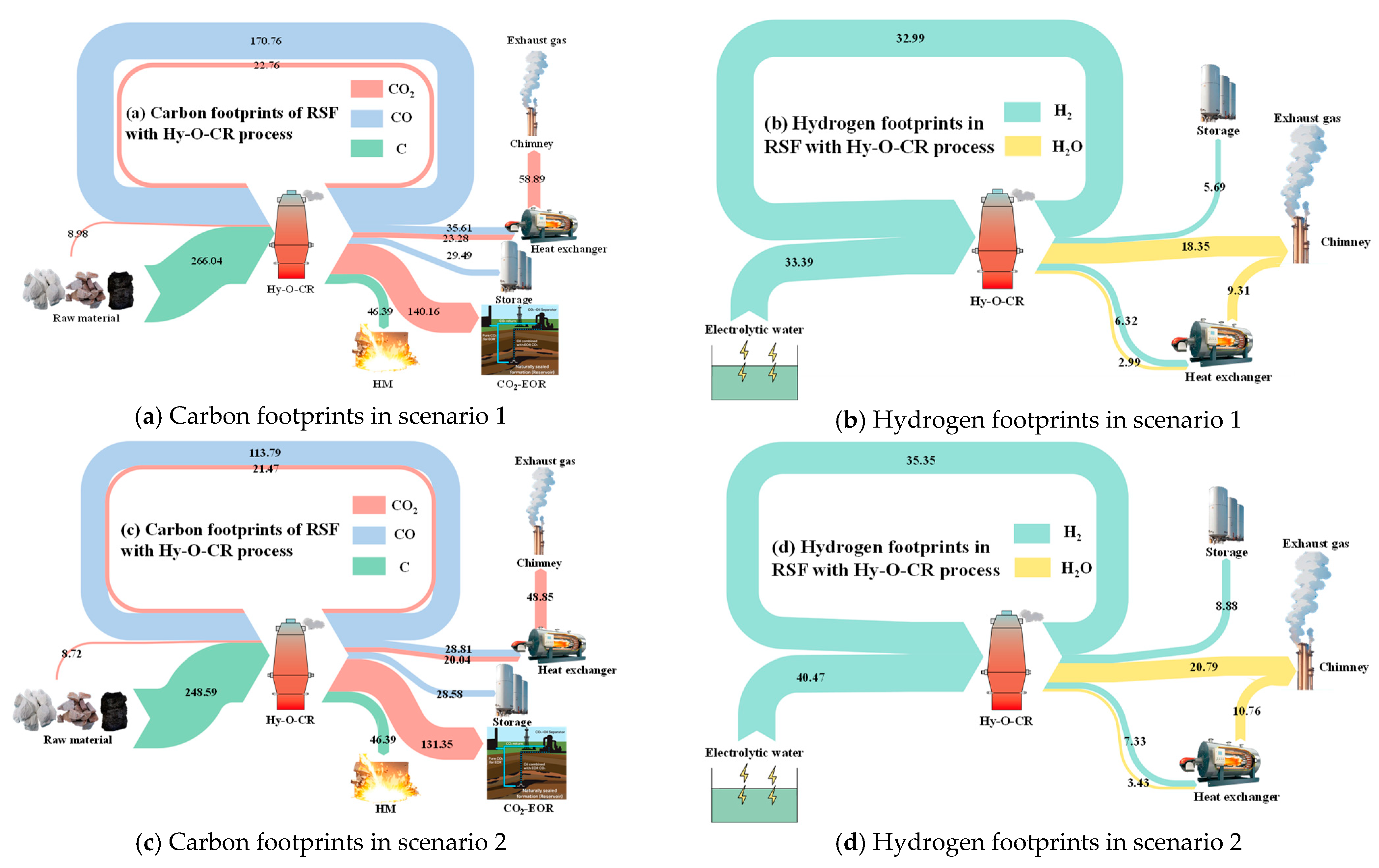
Figure 6 shows the carbon and hydrogen footprints in two different scenarios. The main sources of carbon in the new process flow are coke and carbon-containing reducing gas (CO and CO2) injected into the RSF shaft tuyere. The main expenditures include the form of [Fe3C] entering the carbon-containing hot metal and carbon-containing gases (CO and CO2) discharged from the top of the furnace in gas form. After being processed by different top gas purification devices, a portion of the carbon-containing gas of the top gas is burned and directly released into the atmosphere in the form of CO2, while the remaining gas is captured by the CO2 separator and used as a kind of gas source for oil displacement underground. The rest of the gas is recycled in the form of CO.
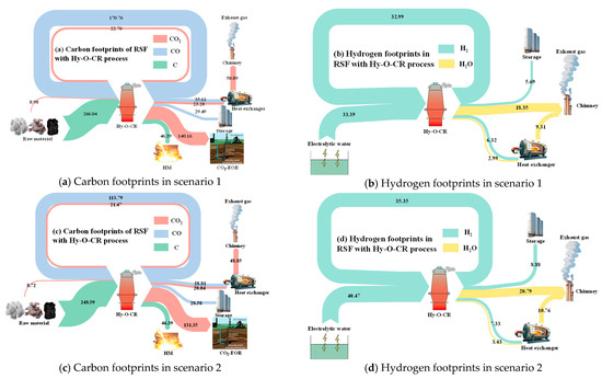
Figure 6.
Footprint analysis of carbon and hydrogen in different scenarios.
There are two main sources of hydrogen in the new process flow. In addition to the moisture in the raw materials and volatiles from coke, the vast majority comes from green hydrogen produced by the electrolysis of water. After passing through the RSF, the product is water, a portion of which is released into the atmosphere after combustion for heat generation, while the rest is removed from the dryer and stored for recycling.
In Figure 6a,b of scenario 1, the boundary conditions were the temperature of the reducing gas (Tredu = 950 °C), the CO ratio (φCO_redu = 30%) of the reducing gas, the temperature of the top gas (Ttop_gas = 200 °C), the water–gas reaction ratio in the RSF (φwater_gas = 20%), and the metallization rate (MR = 90%) of iron ore in the bottom of the RSF shaft. In Figure 6c,d of scenario 2, the boundary conditions were Tredu = 950 °C, φCO_redu = 20% Ttop_gas = 200 °C, φwater_gas = 30%, and MR = 95%. The data presented in the figure refer to the mass of C or H elements expressed in different ways of CO2, CO, C, H2O, and H2, kg/tHM.
Through a comparative analysis of the two cases, it can be observed that with the variation of the operating parameters, the carbon content in the circulating gas, CO, decreased from 170.76 kg/tHM to 113.79 kg/tHM, and the carbon content in CO2 also decreased accordingly, from 22.76 kg/tHM to 21.47 kg/tHM. The mass of hydrogen in circulation increased from 32.99 kg/tHM to 35.35 kg/tHM, but the amount of hydrogen supplemented through the electrolysis of water also increased from 33.39 kg/tHM to 40.47 kg/tHM.
The emission of CO2 is a crucial parameter for measuring and evaluating the new process model. Compared to traditional BF processes, this new process results in lower direct CO2 emissions. Based on an analysis of the two cases, the direct CO2 emissions decreased from 58.89 Nm3/tHM (equivalent to CO2 emissions of 215.93 kg/tHM) to 48.85 Nm3/tHM (equivalent to CO2 emissions of 179.12 kg/tHM). In comparison to the CO2 emissions from traditional BFs (1400 kg/tHM), the proportion of direct emission reduction increased from 84.58% to 87.21%. These analyses are based on the CCUS (carbon capture, utilization, and storage) technology in the new process. Alternatively, without CCUS technology, the CO2 emissions would decrease from 729.85 kg/tHM to 660.73 kg/tHM, resulting in an increase in emission reduction proportion from 47.87% to 52.81%. This target value significantly surpasses existing technologies, such as the BF with hydrogen-rich or oxygen-enriched processes, providing a new direction for the technological development of hydrogen metallurgy. It also offers data support for subsequent parameter optimization of this new model.
5. Conclusions
This article systematically introduces the modeling process and assumptions of RSF with Hy-O-CR. Starting from the key factors limiting the reduction of emissions from BFs, this article investigates new low-carbon processes that explore the limits of energy consumption and extreme carbon reduction through integrated technologies, such as top gas recycling at a high temperature and high reducing potential gas injection into the RSF. After systematic research, the following conclusions were obtained.
- The reduction gas injected into the RSF shaft contains a certain proportion of hydrogen. Due to the endothermic reaction of hydrogen reduction of the iron oxides, the thermal balance distribution in the existing BF is disrupted. The new process requires additional heat input to compensate for the heat deficiency during the reduction process. This is achieved by supplying high-temperature reducing gas through the top gas recycling injection in the upper zone and reducing the direct reduction heat in the lower zone (promoting upward heat transfer of high-temperature gas). In the case of a high proportion of hydrogen, calculations and analyses using a thermal balance model in the lower-temperature upper zone and the higher-temperature lower zone confirm that the process can still achieve a balanced process in both the upper and lower zones when the distribution ratio of direct and indirect reduction is changed.
- Under the set constraints, as the CO ratio of the injected reducing gas increases, the total energy consumption of the process shows an upward trend. However, due to the use of top gas recycling heating technology in this process, the operating parameters can be optimized with the goal of achieving 100% utilization of recycled gas. Surplus or insufficient recycled gas will cause waste of resources or increased energy consumption. Therefore, the optimal solution is based on operating conditions obtained from 100% recycling of the top gas.
- Compared to traditional BFs, the new process achieves a significant reduction in CO2 emissions through a high proportion of hydrogen and CCUS technology. Without CCUS technology, the minimum CO2 emissions throughout the process can reach 660.73 kg/tHM, resulting in a 52.81% reduction compared to traditional BFs. With the implementation of CCUS technology, the direct CO2 emissions of the process can be reduced to 179.12 kg/tHM, resulting in an impressive 87.21% reduction compared to traditional BFs.
This hydrogen metallurgy ironmaking process provides a new and exploratory direction for low-carbon processes. The model results can serve as a theoretical reference for future semi-industrial trials of the new process.
Author Contributions
Conceptualization, H.L.; data curation, J.C.; funding acquisition, H.L.; investigation, Z.L.; methodology, H.L.; project administration, H.L.; resources, X.W.; software, H.L.; supervision, H.L.; writing—original draft, J.C.; writing—review and editing, H.L. All authors have read and agreed to the published version of the manuscript.
Funding
Financial support was provided by the National Key R&D Program of China (No. 2022YFE0208100) and the Fundamental Research Funds for the Central Universities (N2225022).
Data Availability Statement
Data are contained within the article.
Conflicts of Interest
Author Xiaoai Wang was employed by HBIS Group Co., Ltd. The remaining authors declare that the research was conducted in the absence of any commercial or financial relationships that could be construed as a potential conflict of interest.
Nomenclature
| BF | Blast furnace |
| tHM | Tonne of hot metal |
| HM | Hot metal |
| tuy | Tuyere |
| MR | Metallization ratio, 85–95, % |
| more | The mass of ore consumption, kg/tHM |
| mcoke | The mass of coke consumption, kg/tHM |
| mslag | The mass of slag production, kg/tHM |
| mHM | The mass of hot metal, 1000 kg |
| mflux | The mass of flux consumption, kg/tHM |
| mdust | The mass of dust production, kg/tHM |
| mi_j | Mass of i in j, mi_j= mdust × ωi_j, kg/tHM |
| ωi_j | Mass fraction of i in j; I is the composition from Table 1 to Table 4, j is ore, coke, slag, HM, flux, and dust, % |
| qDRI | Calorific value of ore at 950 °C, MJ/kg |
| qcoke | Calorific value of coke at 950 °C, MJ/kg |
| qCO | Calorific value of CO at Ttop_gas, MJ/Nm3 |
| qCO2 | Calorific value of CO2 at Ttop_gas, MJ/Nm3 |
| Qi | The heat released by reaction of CO_Fe2O3, H2_Fe2O3, CO_FeO, C_O2, H2O_CO, H2_O2 and CO_O2, MJ |
| R2 | Binary basicity, R2 = 1.15 |
| Ttop_gas | Temperature of top gas, 150–250 °C |
| Tredu | Temperature of reducing gas, 800–950 °C |
| φCO_redu | Proportion of CO in reducing gas, 10–50% |
| φwater_gas | Proportion of water–gas reaction, 10–50% |
| φCH4 | Proportion of CH4, 1% |
| φco_redu | Proportion of CO in reducing gas |
| Hburn_tuy | The amount of heat burned in the tuyere, MJ |
| VCO_top | Volume of CO in furnace top gas, Nm3 |
| VH2_top | Volume of H2 in furnace top gas, Nm3 |
| VCO2_top | Volume of CO2 in furnace top gas, Nm3 |
| VH2O_top | Volume of H2O in furnace top gas, Nm3 |
| Vi_redu | Volume of components in reducing gas; I = CO, H2, CO2, and H2O, Nm3 |
| Qmaterial | The heat of material, including coke, DRI, HM, slag, gas_low, redu_low, gas_up, in_low, out_low, MJ |
| Qloss_low | The loss of heat, 400 MJ |
| qH2 | Calorific value of H2 at Ttop_gas, MJ/Nm3 |
| qH2O | Calorific value of H2O at Ttop_gas, MJ/Nm3 |
| Qj | The heat absorbed by reaction of C_O2, H2_FeO, CO_Fe3O4, H2_Fe3O4, CaCO3, and MgCO3, MJ |
References
- Wang, C.; Zhang, Y.X. Implementation Pathway and Policy System of Carbon Neutrality Vision. Chin. J. Environ. Manag. 2020, 12, 58–64. (In Chinese) [Google Scholar] [CrossRef] [PubMed]
- Shangguan, F.Q.; Zhou, J.C.; Wang, H.F.; Li, X.P. Climate change and decarbonization development of steel industry. Iron Steel. 2021, 56, 1–6. (In Chinese) [Google Scholar]
- Zhu, Q.S. Development pathway analyses for various ironmaking routes with ultra-low CO2 emission. Chem. Ind. Eng. Prog. 2022, 41, 1391–1398. (In Chinese) [Google Scholar]
- Kaoru, N.; Hiroshi, S.; Yutaka, U.; Kazumoto, K.; Koki, N.; Kohei, S.; Yoshinori, M.; Hirokazu, Y. Development of Low Carbon Blast Furnace Operation Technology by using Experimental Blast Furnace. ISIJ Int. 2022, 62, 2424–2432. [Google Scholar]
- Energy Transitions Commission. China 2050: A Fully Developed Rich Zero-Carbon Economy; Energy Transitions Commission: Beijing, China, 2019. [Google Scholar]
- Wang, P.; Ryberg, M.; Yang, Y.; Feng, K.S.; Sami, K.; Michael, H.; Chen, W.Q. Efficiency stagnation in global steel production urges joint supply-and demand-side mitigation efforts. Nat. Commun. 2021, 12, 2066. [Google Scholar] [CrossRef]
- Chikashi, K.; Yoshinori, M.; Hirokazu, Y.; Kohei, S.; Kazumoto, K.; Hiroshi, S.; Kaoru, N.; Yutaka, U.; Koki, N. Influence of Large Amount of Hydrogen Containing Gaseous Reductant Injection on Carbon Consumption and Operation Conditions of Blast Furnace—Development of Low Carbon Blast Furnace Operation Technology by using Experimental Blast Furnace: Part II. ISIJ Int. 2022, 62, 2433–2441. [Google Scholar]
- Quader, M.A.; Ahmed, S.; Dawal, S.Z.; Nukman, Y. Present needs, recent progress and future trends of energy-efficient Ultra-Low Carbon Dioxide (CO2) Steelmaking (ULCOS) program. Renew. Sustain. Energy Rev. 2016, 55, 537–549. [Google Scholar] [CrossRef]
- Li, J.; Kuang, S.; Jiao, L.; Liu, L.; Zou, R.; Yu, A. Numerical modeling and analysis of hydrogen blast furnace ironmaking process. Fuel 2022, 323, 124368. [Google Scholar] [CrossRef]
- Yin, R.Y.; Liu, Z.D.; Shangguan, F.Q. Thoughts on the Implementation path to a carbon peak and carbon neutrality in China’s steel industry. Engineering 2021, 7, 1680–1683. [Google Scholar] [CrossRef]
- Zhang, W.; Dai, J.; Li, C.Z.; Yu, X.B.; Xue, Z.L.; Saxén, H. A Review on Explorations of the Oxygen Blast Furnace Process. Steel Res. Int. 2021, 92, 2000326. [Google Scholar] [CrossRef]
- Shahabuddin, M.; Brooks, G.; Rhamdhani, M.A. Decarbonisation and hydrogen integration of steel industries: Recent development, challenges and technoeconomic analysis. J. Clean. Prod. 2023, 395, 136391. [Google Scholar] [CrossRef]
- Yu, Y.; Wang, X.D.; Luo, Z.G. Low-Carbon Ironmaking System and Method in Reduction and Smelting Furnace with Pure Oxygen and Hydrogen-Rich. China Patent ZL 200210084753.X, 31 January 2023. (In Chinese). [Google Scholar]
- Li, H.F.; Chen, J.R. An Analysis of Long-Process Ironmaking in a Reduction Smelting Furnace with Hydrogen-Enriched Conditions. Metals 2023, 13, 1756. [Google Scholar] [CrossRef]
- Fink, F. Suspension smelting reduction–a new method of hot iron production. Steel Times 1996, 224, 398. [Google Scholar]
- Ohno, Y.; Hotta, H.; Matsuura, M.; Mitsufuji, H.; Satito, H. Development of oxygen blast furnace process with preheating gas injection into upper shaft. Tetsu-Hagane 1989, 75, 1278. [Google Scholar] [CrossRef] [PubMed]
- Van Der Stel, J.; Hattink, M.; Zeilstra, C.; Louwerse, G.; Hirsch, A.; Janhsen, U.; Sert, D.; Grant, M.; Delebecque, A.; Diez-Brea, P.; et al. ULCOS top gas recycling blast furnace process (ULCOS TGRBF). In Research Fund for Coal and Steel (EC), EUR; final report; European Commission: Luxembourg, 2014; p. 26414. [Google Scholar]
- Nie, H.; Yu, A.; Jiao, L.; Mao, X.; Xu, H.; Kuang, S. Numerical Investigation of Shaft Gas Injection Operation in Oxygen-Enriched Ironmaking Blast Furnace. Metall. Mater. Trans. B 2022, 53, 2712–2734. [Google Scholar] [CrossRef]
- Yu, X.; Hu, Z.; Shen, Y. Modeling of hydrogen shaft injection in ironmaking blast furnaces. Fuel 2021, 302, 121092. [Google Scholar] [CrossRef]
- Danloy, G.; Berthelemot, A.; Grant, M.; Borlée, J.; Sert, D.; van der Stel, J.; Jak, H.; Dimastromatteo, V.; Hallin, M.; Eklund, N.; et al. ULCOS-Pilot testing of the low-CO2 Blast Furnace process at the experimental BF in Luleå. Metall. Res. Technol. 2009, 106, 1–8. [Google Scholar] [CrossRef]
- Liu, J.Z. Fundamental Research on Shaft Gas and Cycle Gas Behaviors in Oxygen Blast Furnace; University of Science and Technology Beijing: Beijing, China, 2015. (In Chinese) [Google Scholar]
- Xia, Z.; Jiang, Z.; Zhang, X.; Li, Z.; Lu, Y.; He, Y.; Chen, J. The CO2 reduction potential for the oxygen blast furnace with CO2 capture and storage under hydrogen-enriched conditions. Int. J. Greenh. Gas Control 2022, 121, 103793. [Google Scholar] [CrossRef]
- Zhuo, Y.T.; Hu, Z.J.; Shen, Y.S. CFD study of hydrogen injection through tuyeres into ironmaking blast furnaces. Fuel 2021, 302, 120804. [Google Scholar] [CrossRef]
- Baniasadi, M.; Mauret, F.; Kinzel, K.P.; Philipp, B.; Baniasadi, M.; Castagnola, C.; Saxén, H.; Hojda, S.; Lin, P. Investigating hydrogenous gas injection into the blast shaft and tuyere. In Proceedings of the 8th ECIC (European Coke and Ironmaking Congress) & 9th ICSTI (International Conference on Science and Technology of Ironmaking), Bremen, Germany, 29 August–2 September 2022. [Google Scholar]
- Mapelli, C.; Dall’Osto, G.; Mombelli, D.; Barella, S.; Gruttadauria, A. Future Scenarios for Reducing Emissions and Consumption in the Italian Steelmaking Industry. Steel Res. Int. 2022, 93, 2100631. [Google Scholar]
- Foo, S.Y.; Cheng, C.K.; Nguyen, T.H.; Kennedy, E.M.; Dlugogorski, B.; Adesing, A.A. Carbon deposition and gasification kinetics of used lanthanide-promoted Co-Ni/Al2O3 catalysts from CH4 dry reforming. Catal. Commun. 2012, 26, 183–188. [Google Scholar] [CrossRef]
- Ras, K.D.; Vijver, R.V.; Galvita, V.V.; Marin, G.B.; Geem, K.M.V. Carbon capture and utilization in the steel industry: Challenges and opportunities for chemical engineering. Curr. Opin. Chem. Eng. 2019, 26, 81–87. [Google Scholar] [CrossRef]
- Shen, F.M.; Zhang, W.L.; Zhang, A.J.; Zheng, H.Y.; Ding, Z.M.; Li, J. Regulation of carbon deposition during preparation process of hydrogen-rich reducing gas by natural gas reforming—An application example of H-C-O system mass balance and chemical equilibrium diagram. Iron Steel 2023, 58, 9–16. (In Chinese) [Google Scholar]
- Liu, J.Z.; Xue, Q.G.; Zhang, S.Y.; She, X.F.; Wang, J.S. Carbon deposition reaction based on heating recycling gas of oxygen blast furnaces. Chin. J. Eng. 2014, 36, 592–596. (In Chinese) [Google Scholar]
- Zhang, W.G.; Zhang, Z.W.; Xu, R.S.; Zhang, J.L.; Ye, L.; Zhu, J.F. Effect of hydrogen-rich gas injection on smelting operation of blast furnace. J. Iron Steel Res. 2023, 35, 1065–1073. (In Chinese) [Google Scholar]
- Liu, S.; Liu, X.J.; Lyu, Q.; Zhang, X.S.; Qie, Y.N. Study on the Appropriate Production Parameters of a Gas-injection Blast Furnace. High Temp. Mater. Process. 2020, 39, 10–25. [Google Scholar]
- Qu, Y.X.; Zou, Z.S.; Xiao, Y.P. A Comprehensive Static Model for COREX Process. ISIJ Int. 2012, 52, 2186–2193. [Google Scholar] [CrossRef]
- Shao, L.; Xu, J.; Saxén, H.; Zou, Z.S. A numerical study on process intensification of hydrogen reduction of iron oxide pellets in a shaft furnace. Fuel 2023, 348, 128375. [Google Scholar] [CrossRef]
- Liu, X.C.; Shi, E.Z.; Zhao, Z.C.; Xu, J.C.; Tang, J.; Chu, M.S. Research on preparation of pellets with different metallization rates under hydrogen-based shaft furnace condition. Sinter. Pelleting 2022, 47, 58–64. (In Chinese) [Google Scholar]
- Bernasowski, M. Theoretical Study of the Hydrogen Influence on Iron Oxides Reduction at the Blast Furnace Process. Steel Res. Int. 2014, 85, 670–678. [Google Scholar] [CrossRef]
- Nogami, H.; Kashiwaya, Y.; Yamada, D. Simulation of Blast Furnace Operation with Intensive Hydrogen Injection. ISIJ Int. 2012, 52, 1523–1527. [Google Scholar] [CrossRef]
- Negri, E.D.; Alfano, O.M.; Chiovetta, M.G. Direct reduction of hematite in a moving-bed reactor. Analysis of the water gas shift reaction effects on the reactor behavior. Ind. Eng. Chem. Res. 1991, 30, 474–482. [Google Scholar] [CrossRef]
- Alamsari, B.; Torii, S.; Trianto, A.; Bindar, Y. Heat and mass transfer in reduction zone of sponge iron reactor. ISRN Mech. Eng. 2011, 2011, 324659. [Google Scholar] [CrossRef]
- Kemppainen, A.; Alatarvas, T.; Iljana, M.; Haapakangas, J.; Mattila, O.; Paananen, T.S.; Fabritius, T. Water-gas Shift Reaction in an Olivine Pellet Layer in the Upper Part of Blast Furnace Shaft. ISIJ Int. 2014, 54, 801–809. [Google Scholar] [CrossRef]

Disclaimer/Publisher’s Note: The statements, opinions and data contained in all publications are solely those of the individual author(s) and contributor(s) and not of MDPI and/or the editor(s). MDPI and/or the editor(s) disclaim responsibility for any injury to people or property resulting from any ideas, methods, instructions or products referred to in the content. |
© 2024 by the authors. Licensee MDPI, Basel, Switzerland. This article is an open access article distributed under the terms and conditions of the Creative Commons Attribution (CC BY) license (https://creativecommons.org/licenses/by/4.0/).