Article

Experimental and Crystal Plasticity Finite Element Investigations of Plastic Anisotropy in Additively Manufactured Ti6Al4V Alloy

1
School of Mechanical and Electrical Engineering, Suqian University, Suqian 223800, China
2
School of Mechanical Engineering, Jiangsu University, Zhenjiang 212013, China
*
Authors to whom correspondence should be addressed.
Metals 2024, 14(1), 130; https://doi.org/10.3390/met14010130
Submission received: 26 December 2023 / Revised: 20 January 2024 / Accepted: 21 January 2024 / Published: 22 January 2024

Abstract

:
Additive manufacturing, particularly the laser powder bed fusion (LPBF) technique, has ushered in a new era of intricate metallic component fabrication, leveraging the exceptional performance of the Ti6Al4V alloy. However, the intricate mechanical behavior of additively manufactured Ti6Al4V, particularly its anisotropic attributes stemming from non-equilibrium microstructures, presents a formidable challenge. In this study, we embark on a comprehensive exploration of the anisotropic mechanical properties exhibited by LPBFed Ti6Al4V alloy. The interplay between microstructure and tensile response is unraveled by integrating experimental investigations with crystal plasticity finite element (CPFE) simulations. The acquired empirical data with CPFE model predictions are harmonized through systematic tensile tests along distinct processing orientations. The results unveil the genesis of plastic anisotropy within the LPBFed Ti6Al4V alloy, ascribed to the emergence of columnar grains meticulously aligned along the building direction, despite the intricate material microstructure inherent to additive manufacturing. These findings collectively furnish a holistic comprehension of the intricate nexus between material attributes and the mechanical manifestations intrinsic to metal components realized through additive manufacturing modalities.

1. Introduction

The pervasive adoption of additive manufacturing (AM) technology has ushered in transformative advancements across critical sectors, including aerospace, national defense, and mold making, propelling the imperative to discern the intricate mechanics underpinning the performance of AM metal materials. Among the diverse array of AM methodologies, the laser powder bed fusion (LPBF) technique has emerged as a prominent contender, celebrated for its capacity to fabricate high-performance components distinguished by exceptional microstructural attributes and mechanical prowess [1,2,3]. However, the mettle of LPBFed metal materials is often imbued with non-equilibrium microstructures, endowing them with intriguing mechanical dynamics that merit closer scrutiny [4,5].
The microstructural idiosyncrasies characteristic of materials borne from additive manufacturing are poised to engender substantive deviations in their mechanical comportment compared to their conventionally manufactured counterparts [6,7]. Notably, the LPBF methodology, a vanguard within the AM pantheon, introduces profound thermal gradients and heterogeneous stresses as a consequence of the localized thermal flux resultant from laser–material interactions, rapid quenching rates, and a stratified layer-by-layer assembly protocol [8,9,10,11,12]. The intricate thermal milieu engendered during LPBF is orchestrated by a plethora of process parameters encompassing the intrinsic attributes of the powder, the thermokinetic specifics of the laser, and the ambient conditions during processing [13]. In the context of the extensively employed α + β dual-phase Ti6Al4V alloy, the proclivity for anisotropic deformation behavior in AM-fabricated components is predominantly ascribed to their microstructural constitution, notably the manifestation of columnar grains that arise congruent with the build direction (BD) [14]. Earlier investigations have eloquently demonstrated that the yield strength and ultimate tensile strength of AM metals are conspicuously amplified in a direction perpendicular to the BD (⊥BD) relative to the uniaxial tensile evaluations conducted parallel to the BD [15,16,17,18]. This propensity for anisotropic tensile strength finds its rationale in the role played by columnar grains, which, subjected to the most pronounced thermal gradients during the AM process, function as formidable impediments to the glide of dislocations, thereby auguring a heightened yield strength in the context of the ⊥BD tensile assessments [7,14,19]. The strategic deployment of columnar grains provides a heightened density of grain boundaries that serve as impediments to dislocation propagation, thus endowing the material with augmented strength perpendicular to the BD when juxtaposed with the uniaxial tensile tests conducted along the BD [20]. Nonetheless, the extant insights into the intricate interplay between microstructural constituents such as columnar grains and lath structures and their cumulative influence on the mechanical properties of LPBFed Ti6Al4V alloys beckon for further exploration.
A salient approach in deciphering the confluence of microstructure and mechanical response, especially within the ambit of polycrystalline materials, is proffered by the crystal plasticity finite element (CPFE) method. This method has emerged as a robust paradigm for unraveling the complex nuances of material behavior across length scales. In the domain of AM, CPFE simulations have accorded a commendable vantage point for elucidating the macroscopic retort of diverse materials, embracing exemplars like 316L stainless steels and Ti6Al4V alloys [21,22,23]. Early explorations of Ti6Al4V alloy often simplified microstructural characterization or utilized idealized textural models for computational efficiency [24,25,26,27]. For instance, Thomas et al. [28] investigated microstructure-related properties using a distilled structural framework by Venkatramani [29]. Somlo et al. [30] studied plastic anisotropy in LPBFed Ti6Al4V alloys with periodic representative volume elements. While these approaches revealed the macroscopic behavior of AM materials, predicting intricate grain-level deformation was constrained due to limited grain configuration and phase consideration. In CPFE simulations, the representative volume element (RVE) is vital, balancing microstructural fidelity and representativeness. An electron backscattered diffraction (EBSD)-derived RVE is used for elastic–plastic finite element analysis, capturing dual-phase geometry [31,32]. EBSD provided granular insights, but its representativeness could vary. The Voronoi tessellation algorithm addressed this, creating EBSD-based grain-scale models revealing grain dimensions and texture effects [33,34,35,36]. However, for LPBFed Ti6Al4V alloys, where mechanical traits involve granular components, columnar crystals, and lamellar structures, existing grain-scale RVEs have limited coverage.
This present inquiry, a harmonious fusion of empirical examinations and CPFE simulations, embarks upon an expedition to unravel the anisotropic tensile behavior enunciated by LPBFed Ti6Al4V alloys. Envisioned as a bespoke tableau, the RVE is meticulously crafted, eschewing the contours of genuine material microstructures and calibrating granularity to encapsulate salient attributes, encompassing the visage of granular morphology, crystallographic orientations, and phase dispersion. At the heart of this endeavor lies a crystal plasticity (CP) model that stands as a citadel of physical fidelity, etched within the bedrock of crystal plasticity. Constitutive equations, germinating from the hallowed precincts of crystal plasticity theory, coalesce to reflect the intrinsic anisotropy that governs material comportments at the crystal level. The panoramic insights gleaned from both empirical and CPFE simulations coalesce to furnish a compelling tableau, positing that the aforesaid anisotropic tensile behavior finds its genesis in the tapestry of heterogeneous granular distributions.

2. Materials and Methods

2.1. LPBF Process of Ti6Al4V Alloy

In Figure 1a, a Ti6Al4V alloy specimen is additively manufactured through the LPBF modality, employing the RC M250 equipment (Nanjing Zhongke Raycham Laser Technology Co., LTD, Nanjing, China), atop a forged titanium alloy substrate within an argon-protected milieu. The judicious selection of LPBF process parameters, as delineated in Table 1 and informed by antecedent investigations, diligently aims to confer a high apparent density and mitigate porosity in the final constructs [37]. To foster material uniformity, a bidirectional laser scanning strategy, punctuated by a 90° rotation for each stratum, is orchestrated. Evidentiary validation of this process is presented in Figure 1b, a visual testament to the superlative quality of the Ti6Al4V powder instrumentalized in the LPBF orchestration. Derived through gas atomization, the powder acquires commendable attributes including spherical particle morphology, facile flow dynamics, and conspicuous absence of agglomeration or adhesion. The powder’s granulometric spectrum spans from 10 µm to 50 µm.
The ensuing dog-bone-shaped tensile samples are meticulously machined employing electrical discharge machining, followed by a veneer of refinement via silicon carbide (SiC) abrasion. Elaborate specifications of the tensile samples’ dimensions are showcased in Figure 1c,d. In a concerted endeavor to assess the sway of microstructural architecture on tensile performance, this investigation adjoins two specimens of akin geometric contour, disparate solely in their orientation relative to the build direction (BD), with one positioned perpendicular and the other parallel thereto. Tensile evaluations are judiciously conducted at ambient temperature, progressing at a steadfast pace of 1 mm/min, an orchestration masterfully executed via the INSTRON 8801 servo–hydraulic fatigue testing apparatus, augmented by a concomitant extensometer. The localized deformation kinetics and strain dynamics engendered during the tensile assay are assiduously monitored through an in situ stretching observation setup, constituting the ZEISS AxioScope metalloscope (Zeiss Microimaging GmbH, Jena, Germany), CARE Measurement & Control Co IBTC-5000 in situ tensile testing machine (CARE Measurement & Control Co., Ltd., Tianjin, China) and VIC-2D Digital Image Correlation (DIC) software 1.0. Parallelly, a sequence unfolds whereby the tensile samples are judiciously thinned to a thickness of 1 mm via grinding and polishing mediated by SiC papers, a prelude to the subsequent imposition of a black and white speckle configuration, aptly hued to align with DIC tracking requisites.

2.2. Microstructure of the LPBFed Ti6Al4V Sample

The microstructural attributes of the LPBFed Ti6Al4V specimen are subjected to a comprehensive inquiry facilitated by a diverse assemblage of characterization methodologies. Optical microscopy (OM), scanning electron microscopy (SEM), electron backscatter diffraction (EBSD), and transmission electron microscopy (TEM) converge in an orchestrated endeavor to unravel the intricate fabric of the material’s constitution. Initiating this investigative trajectory, preparatory rituals of mechanical polishing and chemical etching are meticulously applied to the specimen preceding OM and SEM examinations. These judicious procedures serve to elevate the material’s transparency, granting insights into its inherent features. The subsequent invocation of EBSD and TEM methodologies unfurls a more profound exploration, delving into localized orientation distributions and microstructural configurations latent within the pristine fabrication. Foraying into the domain of TEM analysis mandates an exacting regimen of meticulous preparation. A chronicle of mechanical thinning followed by judicious jet-polishing, enacted via the Tenupol-5 apparatus (Struers™, Champigny sur Marne, France), culminates in a specimen primed for TEM scrutiny, a medium of inquiry wherein heightened scrutiny and nano-scale perusal reveal the material’s cryptic architecture.
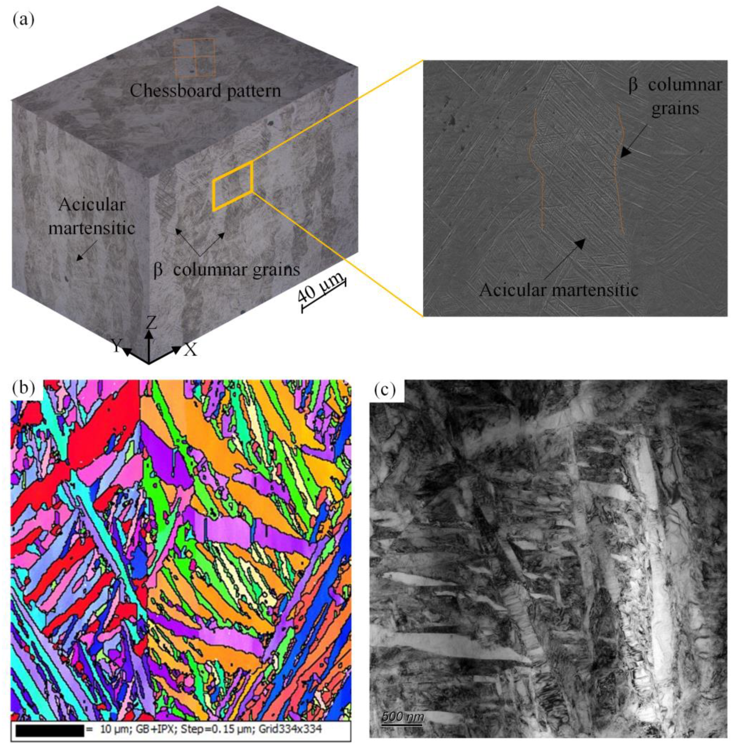
Figure 2 presents a comprehensive three-dimensional overview of the LPBFed Ti6Al4V sample, offering valuable insights into its microstructure morphologies from different perspectives. Notably, the grains in the XY plane exhibit a distinctive checkerboard pattern, with alternating light and dark regions corresponding to different crystal orientations. Moreover, the XZ and YZ planes showcase the formation of epitaxial columnar structures, characterized by an average width of approximately 20 µm. These columnar grains demonstrate a remarkable growth along the building direction, traversing multiple cladding layers without exhibiting discernible overlapping tracks. This phenomenon can be attributed to the temperature gradient within the molten pool along the BD during the LPBF process ranging from 1000 to 2000 K/mm, which is considered high compared to other processing techniques. Specifically, the unfused columnar grains located at the cooler bottom region act as nucleation sites during the solidification of the re-melted layer. Previous investigations have indicated that these columnar grains typically display a distinct texture orientation of <100> [38,39]. Furthermore, a detailed examination of the internal microstructure in the XZ plan view, as revealed by SEM imaging, highlights the presence of fine acicular martensitic α laths within the columnar crystals.
To further explore the local orientation distribution and microstructural morphology in the XZ plane, the EBSD and TEM analyses are performed. As illustrated in Figure 2b,c, extremely fine acicular martensitic α laths with high aspect ratios are obvious, whose width ranges from 0.1 µm to 10 µm. The EBSD analysis indicates that the orientations of α laths in the XZ plane show the characteristics of random distribution. The TEM images reveal that the as-fabricated Ti6Al4V material contains a relatively high dislocation density and twin deformation, which can be attributed to the thermally induced stress during rapid solidification. However, the dislocation density and twin deformation are ignored, as the current study focuses on the effects of columnar crystal and acicular martensitic.

2.3. CPFE Modelling

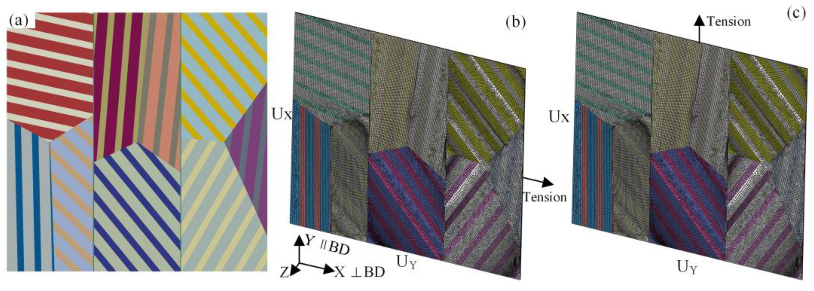
A quasi-three-dimensional grain aggregate finite element model for the LPBFed Ti6Al4V alloy based on the measurement results is established. A representative volume with dimensions of 60.4 × 60.4 × 0.2 μm3 is initially constructed. Then, it is uniformly divided into three parts along the length, each part corresponding to a prior grain. Inside the prior grains, there is an artificial microstructure with continuous parallel α laths, as shown in Figure 3a. Each prior grain is randomly divided into three sub-grains by the trisecting points. Each sub-grain is then divided into two randomly orientated sub-sub-grains, namely α laths. The lath thicknesses are 25 μm and 15 μm, respectively. The process is automated on the ABAQUS platform (version 2017, Dassault Systèmes Simulia Corp., Providence, RI, USA) using the Python language. The corresponding texture distribution illustrates that different colors represent different sets. The as-built model is meshed with 22,623 eight-node brick elements (C3D8) and 45,796 nodes. The model employes a single element through the Z direction, with a length corresponding to the extent of the model along the Z-axis, which is 0.2 μm. The boundary conditions for the pure tension simulation are depicted in Figure 3b,c. Displacement control is applied to the top surface, with the displacement increasing linearly from 0 to 6 μm over time. A uniform and consistent macroscopic strain rate, denoted as 0.001 s−1, stands as the governing parameter pervading all ensuing simulations. When the load is along the ⊥BD direction, the UX surface is completely fixed, indicating x = 0, y = 0, z = 0 on the surface. On the other hand, when the load is along the BD direction, the UY surface is entirely fixed.
A physics-based CPFE constitutive model, finely tailored to encapsulate the distinctive anisotropic plastic deformations exhibited by the LPBFed Ti6Al4V alloy, is artfully introduced. The foundational tenets of crystal plasticity theory, meticulously elucidated in references [40,41,42], underpin the conceptual underpinnings of this model. The flow behavior of the slip system χ is described by Orowan’s law:
γ ˙ χ = ρ m ν ( b χ ) exp ( Δ F K T ) sinh ( Δ V χ K T ( τ χ τ c χ ) )
where ρ m characterizes the mobile dislocation density, while ν represents the dislocation jump frequency. The magnitude of the Burgers vector ( b χ ) delineates the lattice distortion associated with dislocation motion. The thermal activation energy for pinned dislocation ( Δ F ) is a crucial determinant, influenced by both the Boltzmann constant ( K ) and the prevailing temperature (T). These factors collectively contribute to the activation volume ( Δ V χ ), adding a nuanced dimension to dislocation dynamics.
Furthermore, the resolved shear stress ( τ χ ) acting on the slip system is ascertained through the projection of the stress tensor. Of paramount significance is the critical shear stress ( τ c χ ), a pivotal threshold dictating dislocation motion:
τ c χ = τ c , 0 χ + G 12 b χ ρ S S D + ρ G N D
where τ c , 0 χ symbolizes the initial critical resolved shear stress and G 12 stands for the modulus. Statistically stored dislocation (SSD) density ( ρ S S D ) follows a linear trend in relation to the effective plastic strain rate:
ρ ˙ S S D = λ 2 3 D P : D P
where λ represents the hardening coefficient and D P denotes the plastic deformation rate.
The tensor G of geometrically necessary dislocation (GND) densities can be divided into nine separate components:
δ = 1 9 ρ G N D , δ d ¯ δ t ¯ δ = 1 b G
where d ¯ δ and t ¯ δ present the closed packed direction and a vector as defined in ref. [43]. G is calculated using the Nye equation [44]:
G = F p ×
where F p is the curl of the plastic deformation gradient.
The integration of all equations is realized through a user subroutine UMAT, which has been incorporated into the ABAQUS/Standard finite element software utilizing the FORTRAN programming language. This implementation takes into account both the BCC and HCP crystal structures in the context of the dual-phase LPBFed Ti6Al4V alloy. The HCP structure exhibits an aspect ratio of 1.587 (a/c) and encompasses three principal slip system families: 3 X (0001)<11-20> basal slip systems, 3 × (00-10)<11-20> prismatic slip systems, and 12 X (00-11)<11-23> pyramidal slip systems. Detailed in Table 2, the parameters for the dual-phase UMAT are adapted from established investigations [45,46,47]. To validate the calibrated models, a comparison between the stress–strain curves simulated by the model and the experimental data obtained from tension tests is performed. The values of the elastic constants and the initial critical resolved shear stress τ c , 0 χ are then iteratively adjusted until a satisfactory agreement is achieved between the experimental observations and the simulated outcomes [46,47].

3. Results and Discussion

3.1. Anisotropic Mechanical Properties

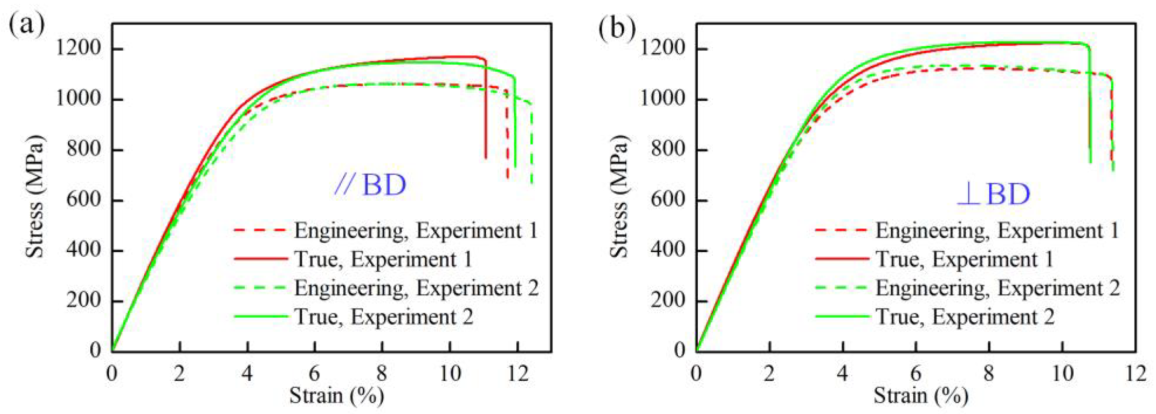
Figure 4 gives the engineering and true stress–strain curves directly obtained as experimental data from the tensile testing device used in the experiments. The tensile experiments are repeated two times for each sample orientation, and the results are found to be consistent. There is a significant difference in ductility and strength between the horizontal sample (⊥BD) and vertical sample (//BD), indicating the tensile anisotropy of the LPBFed Ti6Al4V alloy. The results show that the ultimate tensile strength (UTS) of the horizontal sample surpasses that of the vertical sample by 5.6%. In contrast, the vertical sample shows more excellent elongation before fracture, which is consistent with the results in the literature [48,49].
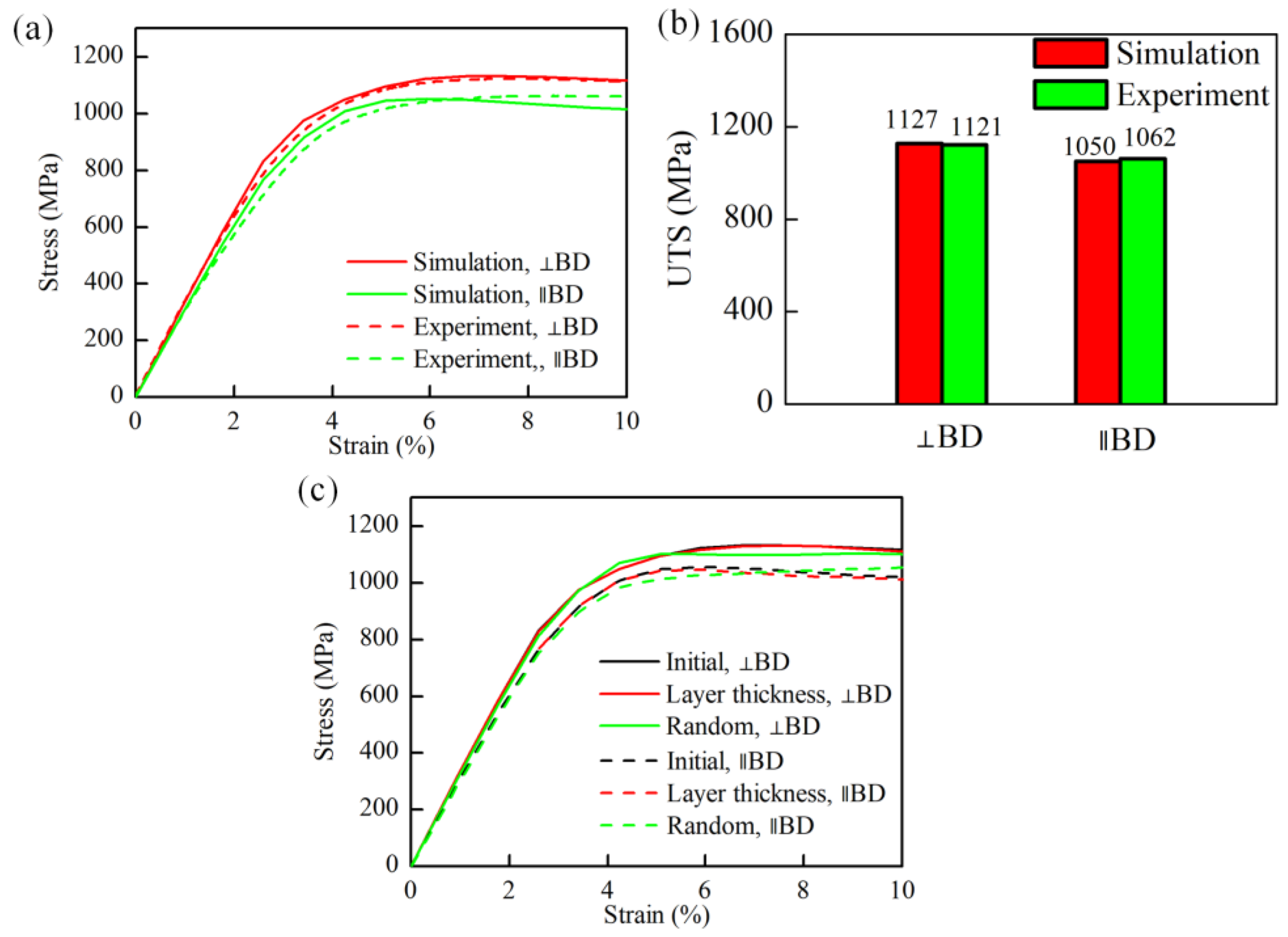
Figure 5 illustrates the mechanical response of the experimental and simulation results under different uniaxial tensile directions. Under uniaxial tensile loading, the simulated true stress–strain behavior can qualitatively predict the experimental trend. Both the experimental and simulated results exhibit strong anisotropy during the tensile process. The material response of the LPBFed Ti6Al4V alloy indicates that the strength in the ⊥BD is greater than that in the BD. In addition, a sensitivity analysis is conducted to assess the influence of lath thickness and random orientation on the model’s convergence. As shown in Figure 5c, the simulation results indicate that variations in the lath thickness, and random orientations have a minor impact on the tensile stress–strain curve and the observed trend in UTS across different tensile directions.

3.2. Effects of Columnar Grains

Figure 6 shows DIC contour maps of the horizontal and vertical samples at 10.0% strain. A significant difference in the heterogeneous strain distribution can be observed. However, both strain distributions represent the common characteristics along the forming direction. The strain change curves along the A–B and C–D lines also reflect the inhomogeneous deformation of both the samples during the tensile process, which can be attributed to columnar grains along the forming direction and non-uniform α laths. The columnar grains divide the sample into different regions where α laths with different crystallographic orientations exist. In addition, the significant plastic strain in the red region indicates the possible location where the fracture occurs.
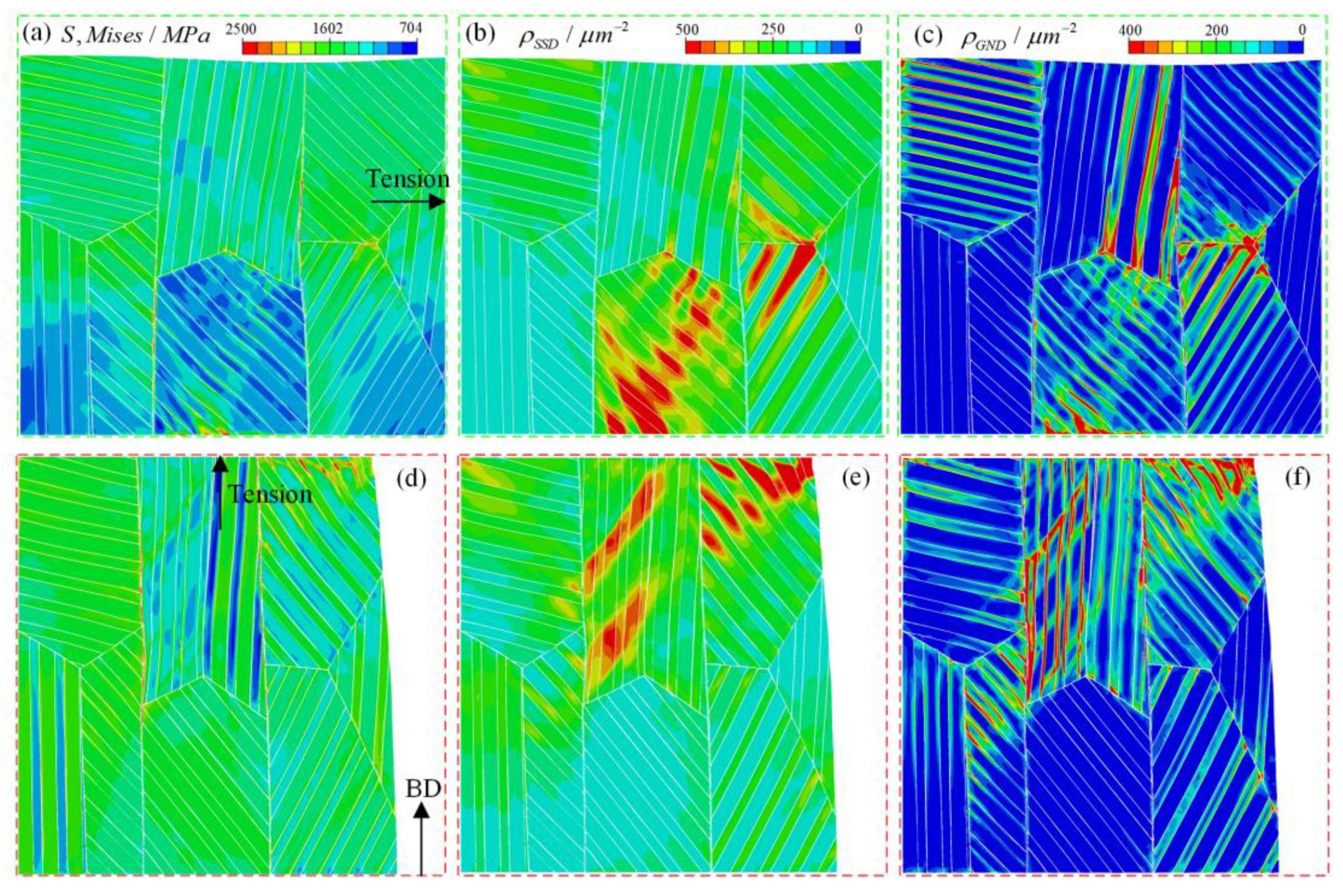
Figure 7a,d presents contour plots illustrating the von Mises stress distribution at a strain of 10.0%. Evidently, distinct stress patterns emerge under varying loading directions. In the case of tension perpendicular to the build direction (⊥BD), the stress concentration is conspicuous within the mid-region of the sample, aligned parallel to the build direction. This concentration is particularly pronounced in α laths characterized by crystallographic orientations conducive to slip. Such behavior is attributed to the robust microstructural stress distribution. The presence of α lath interfaces and grain boundaries creates property discontinuities that impede dislocation movement, thereby inducing heterogeneous deformation. Conversely, under tensile loading along the build direction (BD), stress distribution is more uniform, although localized stress concentrations manifest at grain boundaries. Plastic deformation across distinct independent slip systems is facilitated within individual grains. However, the existence of grain boundaries within the columnar grains curtails plastic deformation, thereby engendering stress and strain disparities along the columnar structure. Notably, this observation corroborates findings from digital image correlation (DIC) experiments, as depicted in Figure 6.
Figure 7b,c,e,f illustrates the spatial distribution of statistically stored dislocation (SSD) and geometrically necessary dislocation (GND) densities at a strain of 10.0% under uniaxial tensile loading for different directions. A discernible resemblance emerges between the overall characteristics of SSD and GND distributions and the von Mises stress distribution. Notably, the amplitude and spatial arrangement of plastic deformation during loading ⊥BD markedly contrast with those under loading BD. In the latter scenario, a more homogeneous plastic deformation field manifests in comparison. The morphological attributes of columnar grains, particularly the presence of grain boundaries, introduce substantial impediments to dislocation mobility during loading perpendicular to the build direction. Conversely, loading along the build direction enables dislocations to glide across α lath interfaces, grain boundaries, and slip planes, thus promoting uniform plastic deformation. In contrast, under ⊥BD loading, plastic deformation predominantly localizes along grain boundaries, accentuating the stress concentration within the columnar grain’s boundary. The congruity in the stress distribution characteristics between the simulation and experimental findings, along with the consistent acknowledgment of the influence of columnar crystals, serves to underpin the reliability of the simulation outcomes.

3.3. Fracture Morphology of Tensile Experiments

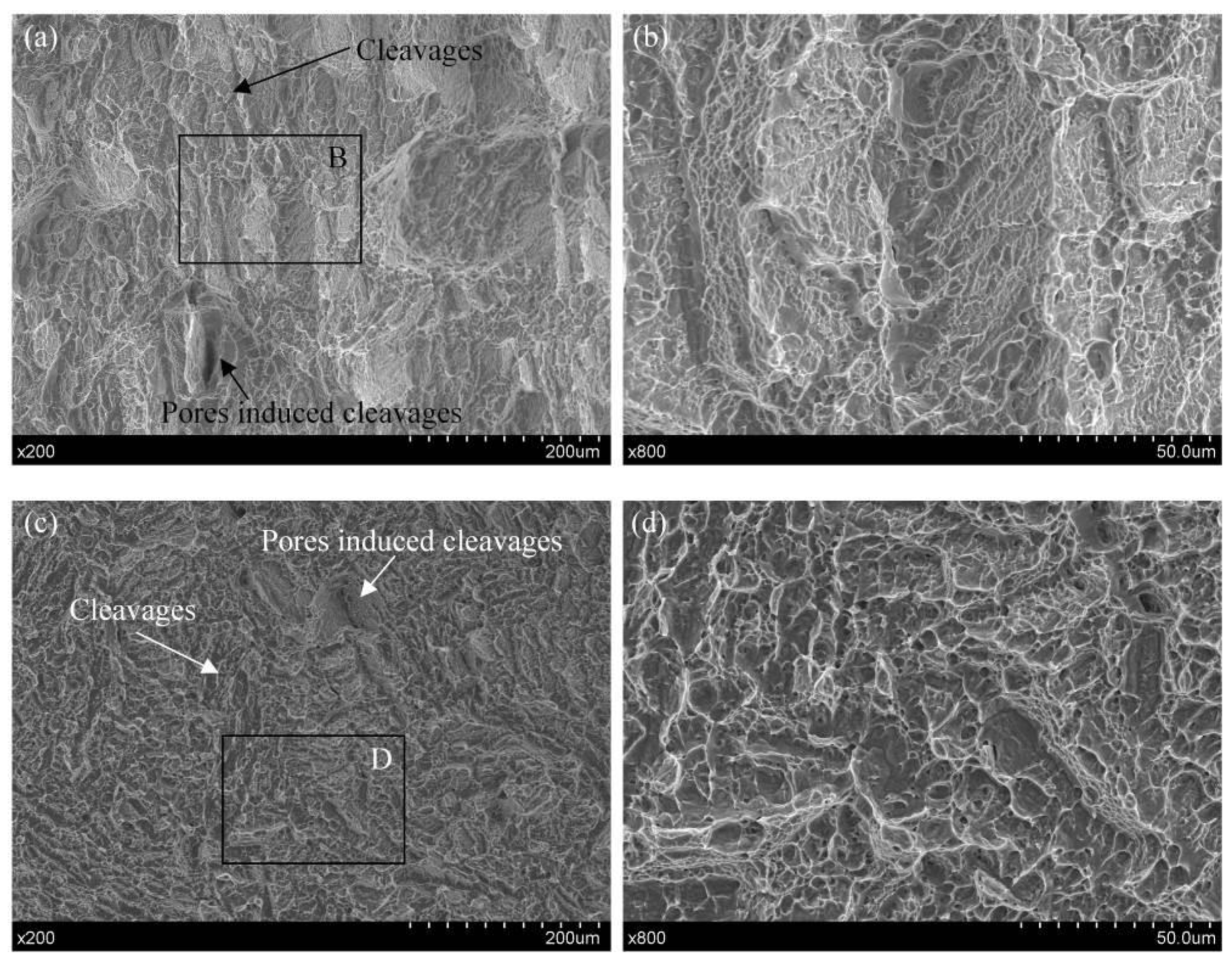
Examination of the fracture surfaces provides valuable insights into the interplay between the microstructural attributes of the LPBFed Ti6Al4V alloy and its tensile properties. Figure 8 presents fracture surface topographies of both horizontally and vertically oriented samples, shedding light on the underlying mechanisms. The comprehensive views of fracture surfaces depicted in Figure 8a,c unveil the presence of finely distributed microscopic voids alongside shallow dimple networks, indicative of a ductile rupture mode. However, a distinctive disparity emerges in the fracture behavior of the horizontal sample, as evidenced by the rough and stratified topography showcased in Figure 8b. Notably, discernible vertical cracks, emblematic of columnar grains, manifest within this fracture surface. This observation highlights the initiation and propagation of voids at the interface between α laths and columnar grains, with preferential fractures occurring along the boundaries of the columnar grains. In the context of the vertical sample’s fracture morphology, as depicted in Figure 8d, a contrasting scenario unfolds. Here, the dominance of microscopic voids in the damage progression takes center stage, obviating the presence of vertical cracks. This divergence can be attributed to the distinctive checkerboard pattern characterizing the grain distribution within the feature plane. Furthermore, the conspicuous plastic deformation concentrated at the grain boundaries serves as an incipient point for crack initiation, a phenomenon consistently observed in Figure 7, ultimately culminating in the observed fracture morphology.

4. Conclusions

In summary, this study has encompassed a comprehensive exploration of the mechanical behavior of LPBFed Ti6Al4V alloy through a harmonious integration of CPFE simulations and experimental analyses under uniaxial tensile loading conditions across diverse orientations. The ensuing observations and outcomes offer significant insights, as outlined below:
(1)
The intricate LPBF process engenders the development of columnar grains that align themselves along the build direction, concomitant with the presence of distinctive lath structures.
(2)
Rigorous tensile examinations underscore a marked discrepancy in strength between the material’s behavior perpendicular and parallel to the build direction. The augmented strength exhibited orthogonal to the build direction, compared to its in-line counterpart, manifests in tandem with the strain distribution profiles unveiled by DIC experiments and an analysis of the fracture surfaces, corroborating the pivotal role played by inherent microstructural attributes in dictating the material’s tensile attributes.
(3)
A meticulously formulated finite element model that accurately encapsulates columnar grains and laths has been meticulously developed, bearing apt testimony to its fidelity in replicating plastic responses akin to those unveiled through experimental uniaxial tension tests.

Author Contributions

Conceptualization, Z.W. and M.X.; writing—original draft preparation, Z.W., M.X. and X.L.; writing—review and editing, Q.L., X.H. and H.Z.; funding acquisition, Z.W. and H.Z. All authors have read and agreed to the published version of the manuscript.

Funding

This research was funded by the National Natural Science Foundation of China (Nos. 52305497, 52205371), Natural Science Foundation of Jiangsu Higher Education Institutions of China (No. 23KJB460033), Suqian Sci&Tech program (No. K202307), and Open Project of Key Laboratory of Conveyance Equipment (East China Jiaotong University), Ministry of Education (No. KLCE2022-02).

Data Availability Statement

Data are contained within the article.

Conflicts of Interest

The authors declare no conflicts of interest.

References

  1. Jared, B.H.; Aguilo, M.A.; Beghini, L.L.; Boyce, B.L.; Clark, B.W.; Cook, A.; Kaehr, B.J.; Robbins, J. Additive manufacturing: Toward holistic design. Scr. Mater. 2017, 135, 141147. [Google Scholar] [CrossRef]
  2. Ngo, T.D.; Kashani, A.; Imbalzano, G.; Nguyen, K.T.Q.; Hui, D. Additive manufacturing (3D printing): A review of materials, methods, applications and challenges. Compos. B Eng. 2018, 143, 172–196. [Google Scholar] [CrossRef]
  3. Pasang, T.; Kirchner, A.; Jehring, U.; Aziziderouei, M.; Tao, Y.; Jiang, C.P.; Wang, J.C.; Aisyah, I.S. Microstructure and mechanical properties of welded additively manufactured stainless steels SS316L. Met. Mater. Int. 2019, 25, 1278–1286. [Google Scholar] [CrossRef]
  4. Wang, Z.; Jiang, B.; Wu, S.; Liu, W. Anisotropic tension-compression asymmetry in SLM 316L stainless steel. Int. J. Mech. Sci. 2023, 246, 108139. [Google Scholar] [CrossRef]
  5. Debroy, T.; Wei, H.L.; Zuback, J.; Mukherjee, T.; Zhang, W. Additive manufacturing of metallic components–process, structure and properties. Prog. Mater. Sci. 2017, 92, 112–224. [Google Scholar] [CrossRef]
  6. Liu, L.F.; Ding, Q.; Zhong, Y.; Zou, J.; Wu, J.; Chiu, Y.L.; Li, J.; Zhang, Z.; Yu, Q.; Shen, Z. Dislocation network in additive manufactured steel breaks strength-ductility trade-off. Mater. Today 2018, 21, 354–361. [Google Scholar] [CrossRef]
  7. Sun, Z.; Tan, X.; Tor, S.B.; Chua, C.K. Simultaneously enhanced strength and ductility for 3D-printed stainless steel 316L by selective laser melting. NPG Asia Mater. 2018, 10, 127–136. [Google Scholar] [CrossRef]
  8. Xia, M.; Gu, D.; Yu, G.; Dai, D.; Chen, H.; Shi, Q. Porosity evolution and its thermo-dynamic mechanism of randomly packed powder-bed during selective laser melting of Inconel 718 alloy. Int. J. Mach. Tool Manuf. 2017, 116, 96–106. [Google Scholar] [CrossRef]
  9. Mercelis, P.; Kruth, J.P. Residual stresses in selective laser sintering and selective laser melting. Rapid Prototyp. J. 2006, 12, 254–265. [Google Scholar] [CrossRef]
  10. DW, D.W.B.; Adams, D.P.; Balogh, L.; Carpenter, J.S.; Clausen, B.; King, G.; Reedlunn, B.; Palmer, T.A.; Maguire, M.C.; Vogel, S.C. In situ neutron diffraction study of the influence of microstructure on the mechanical response of additively manufactured 304L stainless steel. Metall. Mater. Trans. A 2017, 48, 6055–6069. [Google Scholar]
  11. Wu, A.S.; Brown, D.W.; Kumar, M.; Gallegos, G.F.; King, W.E. An experimental investigation into additive manufacturing-induced residual stresses in 316L stainless steel. Metall. Mater. Trans. A 2014, 45, 6260–6270. [Google Scholar] [CrossRef]
  12. Shamsujjoha, M.; Agnew, S.R.; Fitz-Gerald, J.M.; Moore, W.R.; Newman, T.A. High strength and ductility of additively manufactured 316L stainless steel explained. Metall. Mater. Trans. A 2018, 49, 3011–3027. [Google Scholar] [CrossRef]
  13. Thijs, L.; Verhaeghe, F.; Craeghs, T.; Van Humbeeck, J.; Kruth, J.P. A study of the microstructural evolution during selective laser melting of Ti–6Al–4V. Acta Mater. 2010, 58, 3303–3312. [Google Scholar] [CrossRef]
  14. Carroll, B.E.; Palmer, T.A.; Beese, A.M. Anisotropic tensile behavior of Ti-6Al-4V components fabricated with directed energy deposition additive manufacturing. Acta Mater. 2015, 87, 309–320. [Google Scholar] [CrossRef]
  15. Wang, F.; Williams, S.; Colegrove, P.; Antonysamy, A.A. Microstructure and mechanical properties of wire and arc additive manufactured Ti-6Al-4V. Metall. Mater. Trans. A 2013, 44, 968–977. [Google Scholar] [CrossRef]
  16. Wang, T.; Zhu, Y.Y.; Zhang, S.Q.; Tang, H.B.; Wang, H.M. Grain morphology evolution behavior of titanium alloy components during laser melting deposition additive manufacturing. J. Alloys Compd. 2015, 632, 505–513. [Google Scholar] [CrossRef]
  17. Ronneberg, T.; Davies, C.M.; Hooper, P.A. Revealing relationships between porosity, microstructure and mechanical properties of laser powder bed fusion 316L stainless steel through heat treatment. Mater. Design. 2020, 189, 108481. [Google Scholar] [CrossRef]
  18. Kramer, S.L.B.; Jones, A.; Mostafa, A.; Ravaji, B. The third Sandia fracture challenge: Predictions of ductile fracture in additively manufactured metal. Int. J. Frac. 2019, 218, 5–61. [Google Scholar] [CrossRef]
  19. Garlea, E.; Choo, H.; Sluss, C.C.; Koehler, M.R.; Bridges, R.L.; Xiao, X.; Ren, Y.; Jared, B.H. Variation of elastic mechanical properties with texture, porosity, and defect characteristics in laser powder bed fusion 316L stainless steel. Mater. Sci. Eng. A 2019, 763, 138032. [Google Scholar] [CrossRef]
  20. Wilson-Heid, A.E.; Qin, S.; Beese, A.M. Multiaxial plasticity and fracture behavior of stainless steel 316L by laser powder bed fusion: Experiments and computational modelling. Acta Mater. 2020, 199, 578–592. [Google Scholar] [CrossRef]
  21. Zhang, J.; Lu, S.; Shi, G.; Xie, W.; Geng, Y.; Wang, Z. A study on a hybrid SERS substrates based on arrayed gold nanoparticle/graphene/copper cone cavities fabricated by a conical tip indentation. J. Mater. Res. Technol. 2022, 22, 1558–1571. [Google Scholar] [CrossRef]
  22. Geng, Y.; Harrison, N. Functionally graded bimodal Ti6Al4V fabricated by powder bed fusion additive manufacturing: Crystal plasticity finite element modelling. Mater. Sci. Eng. A 2020, 773, 138736. [Google Scholar] [CrossRef]
  23. Bronkhorst, C.; Mayeur, J.; Livescu, V.; Pokharel, R.; Brown, D.; Gray, G. Structural representation of additively manufactured 316L austenitic stainless steel. Int. J. Plast. 2019, 118, 70–86. [Google Scholar] [CrossRef]
  24. Goh, C.-H.; Neu, R.W.; McDowell, D.L. Crystallographic plasticity in fretting of Ti–6Al–4V. Int. J. Plast. 2003, 19, 1627–1650. [Google Scholar] [CrossRef]
  25. Mayeur, J.R.; McDowell, D.L. A three-dimensional crystal plasticity model for duplex Ti–6Al–4V. Int. J. Plast. 2007, 23, 1457–1485. [Google Scholar] [CrossRef]
  26. Venkatramani, G.; Ghosh, S.; Mills, M. A size-dependent crystal plasticity finite-element model for creep and load shedding in polycrystalline titanium alloys. Acta Mater. 2007, 55, 3971–3986. [Google Scholar] [CrossRef]
  27. Chatterjee, K.; Echlin, M.P.; Kasemer, M.; Callahan, P.G.; Pollock, T.M.; Dawson, P. Prediction of tensile stiffness and strength of Ti–6Al–4V using instantiated volume elements and crystal plasticity. Acta Mater. 2018, 157, 21–32. [Google Scholar] [CrossRef]
  28. Thomas, J.; Groeber, M.; Ghosh, S. Image-based crystal plasticity FE framework for microstructure dependent properties of Ti–6Al–4V alloys. Mater. Sci. Eng. A 2012, 553, 164–175. [Google Scholar] [CrossRef]
  29. Venkatramani, G.; Kirane, K.; Ghosh, S. Microstructural parameters affecting creep induced load shedding in Ti-6242 by a size dependent crystal plasticity FE model. Int. J. Plast. 2008, 28, 428–454. [Google Scholar] [CrossRef]
  30. Somlo, K.; Frodal, B.; Funch, C.; Poulios, K.; Winther, G.; Hopperstad, O.; Børvik, T.; Niordson, C. Anisotropic yield surfaces of additively manufactured metals simulated with crystal plasticity. Eur. J. Mech. A 2022, 94, 104506. [Google Scholar] [CrossRef]
  31. Sun, X.; Choi, K.S.; Liu, W.N.; Khaleel, M.A. Predicting failure modes and ductility of dual phase steels using plastic strain localization. Int. J. Plast. 2009, 25, 1888–1909. [Google Scholar] [CrossRef]
  32. Azhari, F.; Wallbrink, C.; Sterjovski, Z.; Crawford, B.R.; Menzel, A.; Agiu, D.; Wang, C.H.; Chaffer, G.S. Predicting the complete tensile properties of additively manufactured Ti-6Al-4V by integrating three-dimensional microstructure statistics with a crystal plasticity model. Int. J. Plast. 2022, 148, 103127. [Google Scholar] [CrossRef]
  33. Wang, X.; Cazes, F.; Li, J.; Hocini, A.; Ameyama, K.; Dirras, G. A 3D crystal plasticity model of monotonic and cyclic simple shear deformation for commercial-purity polycrystalline Ti with a harmonic structure. Mech. Mater. 2019, 128, 117–128. [Google Scholar] [CrossRef]
  34. Zhao, N.; Roy, A.; Wang, W.; Zhao, L.; Silberschmidt, V.V. Coupling crystal plasticity and continuum damage mechanics for creep assessment in Cr-based power-plant steel. Mech. Mater. 2019, 130, 29–38. [Google Scholar] [CrossRef]
  35. Hu, L.; Jiang, S.Y.; Zhang, Y.Q.; Zhu, X.M.; Sun, D. Texture evolution and inhomogeneous deformation of polycrystalline Cu based on crystal plasticity finite element method and particle swarm optimization algorithm. J. Cent. South Univ. 2017, 24, 2747–2756. [Google Scholar] [CrossRef]
  36. Liu, W.; Chen, B.K.; Pang, Y. Numerical investigation of evolution of earing, anisotropic yield and plastic potentials in cold rolled FCC aluminium alloy based on the crystallographic texture measurements. Eur. J. Mech. A/Solids 2019, 75, 41–55. [Google Scholar] [CrossRef]
  37. Lu, J.Z.; Lu, H.F.; Xu, X.; Yao, J.H.; Cai, J.; Luo, K.Y. High-performance integrated additive manufacturing with laser shock peening-induced microstructural evolution and improvement in mechanical properties of Ti6Al4V alloy components. Int. J. Mach. Tool Manufact. 2020, 148, 103475. [Google Scholar] [CrossRef]
  38. Baufeld, B.; Biest, O.V.D.; Dillien, S. Texture and crystal orientation in Ti-6Al-4V builds fabricated by shaped metal deposition. Metall. Mater. Trans. A 2010, 41, 1917–1927. [Google Scholar] [CrossRef]
  39. Al-Bermani, S.S.; Blackmore, M.L.; Zhang, W.; Todd, I. The origin of microstructural diversity, texture, and mechanical properties in electron beam melted Ti-6Al-4V. Metall. Mater. Trans. A 2010, 41, 3422–3434. [Google Scholar] [CrossRef]
  40. Rice, J. Inelastic constitutive relations for solids: An internal-variable theory and its application to metal plasticity. J. Mech. Phys. Solids 1971, 19, 433–455. [Google Scholar] [CrossRef]
  41. Wang, Z.; Zhang, J.; Lu, J. Effects of crystallographic orientations and grain boundaries on nanoscratching behaviour of unique bi-crystal Cu. Wear 2022, 498, 204313. [Google Scholar] [CrossRef]
  42. Kalidindi, S.R. Incorporation of deformation twinning in crystal plasticity models. J. Mech. Phys. Solids 1998, 46, 267–290. [Google Scholar] [CrossRef]
  43. Ma, A.; Hartmaier, A. On the influence of isotropic and kinematic hardening caused by strain gradients on the deformation behaviour of polycrystals. Philos. Mag. 2014, 94, 125–140. [Google Scholar] [CrossRef]
  44. Nye, J.F. Some geometrical relations in dislocated crystals. Acta Metall. 1953, 1, 153–162. [Google Scholar] [CrossRef]
  45. Kapoor, K.; Ravi, P.; Noraas, R.; Park, J.-S.; Venkatesh, V.; Sangid, M.D. Modeling Ti–6Al–4V using crystal plasticity, calibrated with multi-scale experiments, to understand the effect of the orientation and morphology of the α and β phases on time dependent cyclic loading. J. Mech. Phys. Solids 2021, 146, 104192. [Google Scholar] [CrossRef]
  46. Waheed, S.; Zheng, Z.; Balint, D.S.; Dunne, F.P.E. Microstructural effects on strain rate and dwell sensitivity in dual-phase titanium alloys. Acta Mater. 2019, 162, 136–148. [Google Scholar] [CrossRef]
  47. Cai, W.; Song, Q.; Ji, H.; Liu, Z. Dual-phase morphology distribution effects on mechanical behaviors of Ti6Al4V via pseudorandom crystal plasticity modeling. J. Mater. Res. Technol. 2022, 17, 2897–2912. [Google Scholar] [CrossRef]
  48. Xie, Z.; Dai, Y.; Ou, X.; Ni, S.; Song, M. Effects of selective laser melting build orientations on the microstructure and tensile performance of Ti–6Al–4V alloy. Mater. Sci. Eng. A 2020, 776, 139001. [Google Scholar] [CrossRef]
  49. Sabban, R.; Bahl, S.; Chatterjee, K.; Suwas, S. Globularization using heat treatment in additively manufactured Ti-6Al-4V for high strength and toughness. Acta Mater. 2019, 1, 239–254. [Google Scholar] [CrossRef]
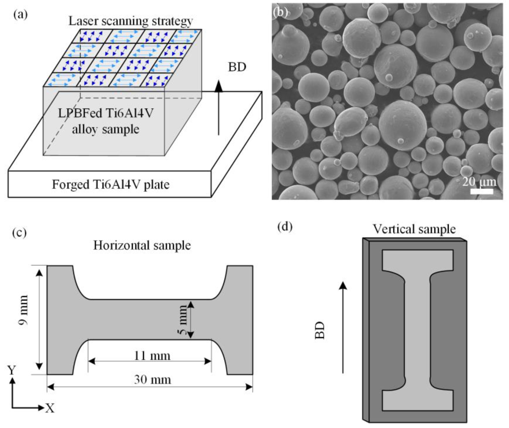
Figure 1. LPBF process of Ti6Al4V alloy. (a) Schedule of the LPBF process. (b) Surface morphology of Ti6Al4V powder. (c) Horizontal sample. (d) Vertical sample.
Metals 14 00130 g001
Figure 2. Microstructure of the LPBFed Ti6Al4V sample. (a) OM and SEM images of the etched morphology. (b) EBSD inverse pole figure (IPF) and (c) TEM images of the XZ plane.
Metals 14 00130 g002
Figure 3. Schematic diagrams of the FEM model. (a) Representative schematic of the α-phase laths, (b,c) boundary conditions and finite element mesh.
Metals 14 00130 g003
Figure 4. Engineering and true stress–strain curves from the tensile experiments. (a) The vertical sample (//BD). (b) The horizontal sample (⊥BD).
Metals 14 00130 g004
Figure 5. (a) Simulated stress–strain curves, (b) comparison of UTS between experimental and simulation results, (c) the effect of lath thickness and random orientations.
Metals 14 00130 g005
Figure 6. The DIC contour maps and strain distributions of the horizontal and vertical samples at 10.0% strain.
Metals 14 00130 g006
Figure 7. CPFE simulation results of ⊥BD tension and //BD tension at 10.0% strain. (a,d) Full−field von Mises stress. (b,e) SSD density. (c,f) GND density.
Metals 14 00130 g007
Figure 8. Fracture surfaces of (a,b) the horizontal sample and (c,d) the vertical sample.
Metals 14 00130 g008
Table 1. Process parameters.
ProcessEnergy SourceDeposition ParametersScanning Strategy
LPBFTypeWavelength
[nm]
Power
[W]
Spot diameter
[μm]
Scanning speed
[mm/s]
Hatch distance
[μm]
Layer thickness
[μm]
Bidirectional with 90° rotation in each layer
Pulsed laser400280100120014030
Table 2. Material parameters in the CPFE model.
Parameterα Phaseβ Phase
Elastic constants
(GPa)
C11 = 89.0
C12 = 39.0
C44 = 24.0
C13 = 42.0
C33 = 126.0
C11 = 68.250
C12 = 53.000
C44 = 30.390
ρ m (μm2)5.71 × 10−25.71 × 10−2
ν (Hz)8.75 × 10128.75 × 1012
b χ (nm)0.2950.286
Δ F 0.42470.3340
K (JK−1)1.38 × 10231.38 × 1023
T (K)293293
Δ V χ (nm3)1.22b32.10 × 10−3b3
τ c , 0 χ (MPa)Basal: 397.95
Prism: 574.21
Pyramidal: 778.0
370.60
G 12 (GPa)40.054.9
Disclaimer/Publisher’s Note: The statements, opinions and data contained in all publications are solely those of the individual author(s) and contributor(s) and not of MDPI and/or the editor(s). MDPI and/or the editor(s) disclaim responsibility for any injury to people or property resulting from any ideas, methods, instructions or products referred to in the content.