Article

Research on the Temperature and Thermal Stress of the Roll Quenching Process of Thin Plates

1
National Engineering Research Center for Equipment and Technology of Cold Strip Rolling, Yanshan University, Qinhuangdao 066004, China
2
State Key Laboratory of Metastable Materials Science and Technology, Yanshan University, Qinhuangdao 066004, China
*
Author to whom correspondence should be addressed.
Metals 2024, 14(1), 83; https://doi.org/10.3390/met14010083
Submission received: 16 December 2023 / Revised: 6 January 2024 / Accepted: 8 January 2024 / Published: 10 January 2024
(This article belongs to the Special Issue Numerical Simulation of Metal Forming Process)

Abstract

:
The roll quenching process can be approximated as a high-pressure jet impinging on a high-temperature moving steel plate. The process can greatly improve the strength and overall mechanical properties of the steel plate. However, the cooling uniformity and other factors lead to the problem of poor plate shape after quenching. It is found that in the roll quenching process, the roller conveyor speed has a large influence on the temperature field and stress field. This paper establishes a roll quenching mechanism model, iterates the convective heat transfer coefficient on the steel plate surface through the inverse heat transfer method, and performs a numerical simulation. Through the numerical simulation of the roll quenching process in the high-pressure zone of the steel plate, the temperature and equivalent force change rule of the transient of each position of the steel plate in the thick direction are obtained. It is found that the plate does not reach its maximum value when it is in the quenching zone, but there is some hysteresis that becomes more pronounced as it gets closer to the core. These findings are valuable for regulating the roll-hardening process and maintaining optimal strip surface quality in industrial production environments.

1. Introduction

In the iron and steel industry, with the strategy of reducing carbon emissions, the medium-thickness plate production line needs to accelerate the search for the ultimate energy-efficiency methods in terms of both equipment upgrading and process optimization [1,2,3]. One effective way is to upgrade from off-line quenching to on-line direct quenching. The steel plate eliminates the process of reheating after rolling. In the quenching process of thin-gauge steel plates, the plate shape problem and its control are the major difficulties [4,5]. Steel plates with poor plate shape after quenching need to be transported to the straightener inlet for re-straightening, which increases the production cycle and equipment usage. Therefore, it is necessary to study the mechanism and temperature field of the roll quenching process for thin-gauge steel plates. A steel mill produces thin-gauge steel plates with warping and edge wave problems, resulting in a lower product quality qualification rate and affecting the production beat of the entire plate production line. In order to study the root cause and treatment measures, this paper utilizes the finite element method to numerically simulate the roll quenching process. The actual convective heat transfer coefficient profile during quenching was obtained by the inverse heat transfer method. Its accuracy is extremely critical for calculating and predicting changes in steel plate temperature during quenching. This simulation is critical for understanding temperature variations during quenching and for evaluating different conditions, such as roller conveyor speed. The insights gained are vital for enhancing the quality and efficiency of steel plate production. Therefore, we investigated the temperature and stress field conditions at different roller conveyor speeds.
Numerous studies have shown that the regulation of quenching temperature has a significant impact on organizational and mechanical properties [6,7,8,9,10]. Shi et al. [11,12] analyzed the effects of water volume, jet angle, and jet pressure on the cooling rate during ultra-rapid cooling. Lei [13] used the average convective heat transfer coefficient constant to replace the convective heat transfer coefficient of the whole process of quenching. Shi [14] presented an experimental study on the convective heat transfer characteristics of a circumferentially arranged oblique jet array impinging on the rotating cylindrical surface in the confined space. In fact, the surface temperature of the steel plate has a large impact on the heat transfer coefficient, and the temperature of the steel plate fluctuates violently during the quenching process [15,16,17,18]. Therefore, the establishment of a convective heat transfer coefficient corresponding to the temperature is necessary to ensure the accuracy of the calculation [19,20]. The study of the law of convective heat transfer coefficient on the surface of steel plate during the quenching process plays a key role in improving the quenching efficiency and forecasting the temperature field distribution of the steel plate [21,22]. At present, most of the research on the quenching process temperature field and stress field uses both the physical experimental method and the numerical simulation method [23,24,25]. Zhang [26] proposed a cooling rate control method based on temperature field for roll quenching of medium-thick plate by studying the cooling rate and cooling effect of steel plate when it passes through the high-pressure and low-pressure zones of the roll quenching machine continuously in the process of roll quenching. The steel plate is too thin to be filled with a sufficient number of thermocouples in the thick direction, and because of the equipment, it is difficult to take into account the effect of the speed of moving the plate on the quenching process [27,28,29]. Some scholars used the finite difference method to simulate the temperature field distribution in the cross-section of a medium-thick plate, and the heat transfer in the length direction of the steel plate was neglected in the calculation and analysis [30,31,32,33,34]. In fact, the temperature field in the direction of the length of the steel plate has a certain degree of influence on both the cooling rate and the stress of the steel plate. Therefore, a three-dimensional thermal coupling model needs to be established to ensure the accuracy of the calculation results.
The roll quenching section of the medium-thickness plate production line is located after the fine rolling exit, aiming at regulating the organization properties of the steel plate after fine crystal strengthening. This on-line direct quenching method increases the content of slat martensite in the quenched organization and significantly improves the strength of the steel plate. Precise cooling path control is the key to regulating tissue properties, and how to achieve a large rate and uniform cooling effect is one of the research focuses. Figure 1 shows the flow chart of the roll quenching process. The high-pressure section is ultra-rapid cooling, including two nozzle forms: a slit nozzle and a high-density nozzle. It can make the austenite-based steel plate after rolling or coming out of the heating furnace with a certain cooling rate to the slaty martensite of rapid transformation to minimize the generation of harmful tissues. The low-pressure section is laminar flow-cooled to cool the steel plate to ambient temperature and reduce residual quenching stresses.
This paper adopts the method of constant correction of the convective heat transfer coefficient. The purpose of this paper is to obtain the accurate quenching process temperature field, steel plate stress field distribution, from which to find the steel plate through different nozzles when the surface and the core of the temperature rate and thermal stress of the change rule, so as to find the reasons for the problems of the plate shape, and then give a feasible control strategy.

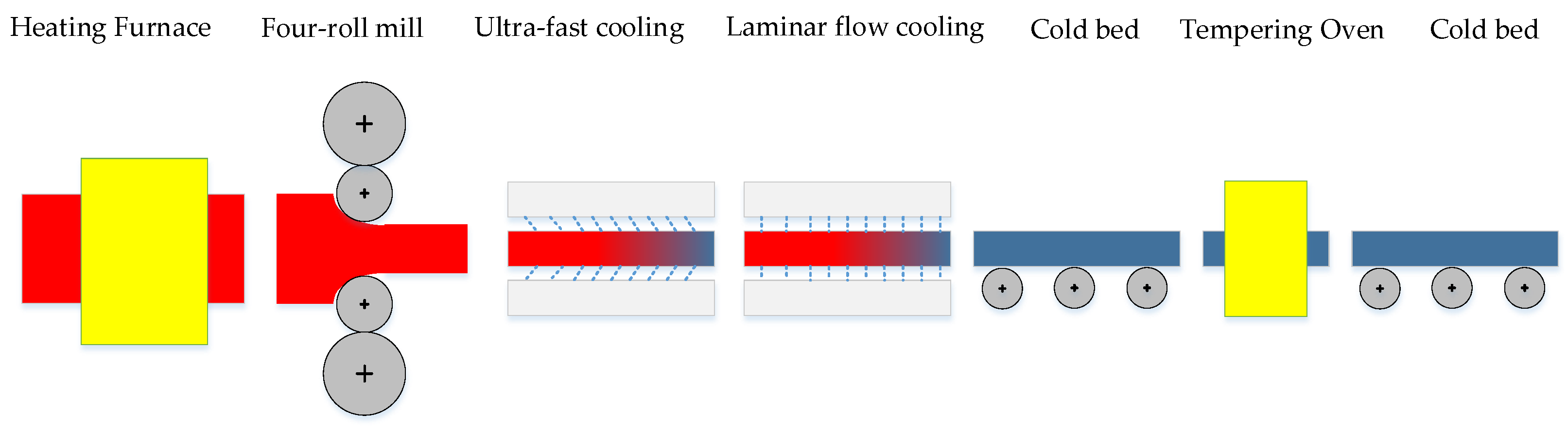
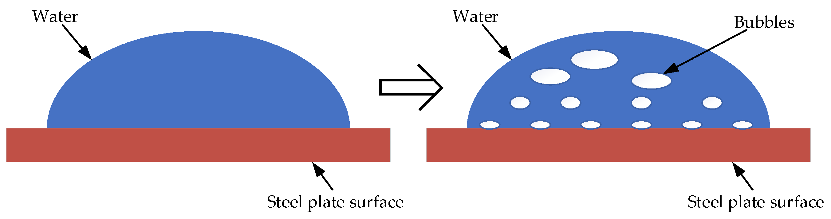
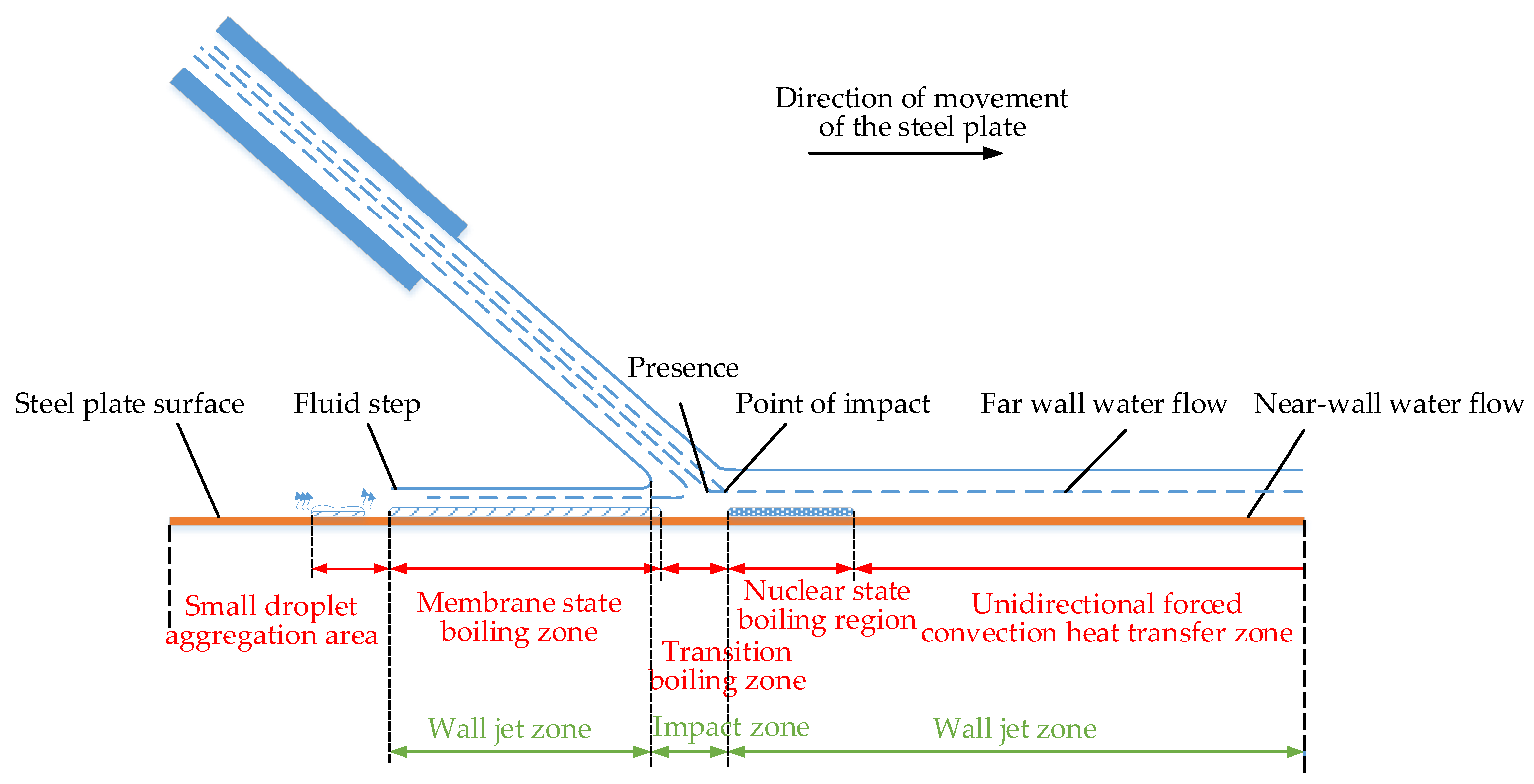
2. Roll Quenching Cooling Mechanism Analysis

2.1. Modeling of Segmented Convective Heat Transfer Coefficients

The steel plate roller quenching process is investigated for high-pressure jet impact on a high-temperature moving steel plate for a strong heat transfer cooling process. In different regions of the surface, cooling water impinging on a stationary high-temperature surface undergoes four stages: film boiling, transient boiling, nuclear boiling, and single-phase convective heat transfer [35,36,37]. The convective heat transfer coefficient of cooling water impinging on its surface is different in different temperature zones. In the high temperature range above 650 °C, a certain pressure of the jet contacts the surface of the steel plate, and when the vaporization process is extremely fast, its surface is always attached to the newly generated high-temperature gases. Water vaporization of high-temperature gases after the temperature and the temperature of the surface of the steel plate are positively correlated. Therefore, the actual temperature gradient affecting the convective heat transfer coefficient between the two media is the temperature difference between the surface of the steel plate and the high-temperature gas produced after the vaporization of cooling water. In the temperature range below 300 °C, the vaporization rate of liquid water in continuous contact with the steel plate is substantially lower than in the high temperature range. At this point, the actual temperature gradient can be approximated as the temperature difference between the surface of the steel plate and the cooling water. The temperature range of 300~650 °C is the transition zone. At this time, the surface of the steel plate is in a mixed transition state of high-temperature gas and cooling water, and the temperature gradient is the largest. Therefore, the convection heat transfer coefficient in this temperature range is the largest. Each stage corresponds to a different convective heat transfer coefficient, which in turn affects the rate of temperature drop on the steel plate surface. The performance of thin-specification steel plates after quenching is required to achieve high strength and high wear resistance to ensure long-term stable use in engineering. The key to its performance is the rapid transformation of the steel plate organization from austenite to martensite in the quenched section of the high-pressure zone. In the controlled cooling process, to determine the target organization while at the same time speeding up the entire quenching speed, the efficiency of the entire production line will be improved. The relationship between convective heat transfer coefficient and quenching capacity is shown in Figure 2.
By increasing the flow rate, increasing the injection pressure, increasing the number of nozzle collectors, and decreasing the speed of the roller conveyor, we can increase the temperature drop rate in the high temperature zone. The roll quenching unit is divided into a high-pressure zone and a low-pressure zone. Three types of nozzles can be arranged in the high-pressure zone: slit nozzles, high-density nozzles, and fast-cooling nozzles with a jet pressure of 0.8 MPa. The jet pressure of the nozzle arranged in the low-pressure zone is 0.4 MPa. The steel plate in the quenching process of the heat transfer relationship is: the surface of the steel plate and cooling water for strong heat transfer; convection heat transfer with the air; heat transfer with the roller conveyor; and the core of the heat conduction. The greatest influence on the surface temperature of the steel plate is the convective heat transfer with the cooling water. The convective heat transfer coefficient, as a key parameter to characterize the cooling capacity, is also the key to studying the temperature field of the quenching process. The convective heat transfer coefficient function for the steel plate roll quenching process is as follows:
h = f T P , T W , P , θ , Q , v P , v E , μ , λ , η
where T P is the surface temperature of the steel plate; T W is the jet temperature; P is the injection pressure; θ is the angle of the jet to the steel plate; Q is the injection flow rate; v P is the speed at which the steel plate moves; v E is the bubble vaporization rate; μ is the surface roughness of the steel plate; λ is the thermal conductivity of the steel plate; and η is the cooling medium dynamic viscosity.
When the cooling water at 24 °C impinges on the surface of a high-temperature steel plate at 810 °C, the convective heat transfer coefficient of the impinging region of the plate surface varies with the temperature. This is related to the state of water on the high-temperature steel plate and the cooling mechanism. Under normal circumstances, the cooling water is in the form of drops in contact with the high-temperature steel plate, and its state changes from water vaporization to water vapor; energy conversion is completed in an instant, as shown in Figure 3. Cooling water with a certain jet velocity and pressure impact on the surface of the high-temperature steel plate contributes to enhanced convection heat transfer. Due to the increase in the flow rate per unit of time, the surface of the steel plate will be formed by a certain thickness of water covered by the impact area of the jet. In the impact area, water and high-temperature steel plate contact will immediately vaporize into water vapor, which forms a bubble with the water’s upward movement. The movement process leads to a reduction in the contact area and tightness between the water film and the steel surface, and the layer closest to the surface of the steel plate is a mixture of liquid water and gaseous water. The formation of bubbles on the surface of the steel plate will lead to the deterioration of heat transfer. Different temperatures of the steel surface affect the water vaporization rate and bubble rise rate, directly affecting the surface of the quenching of the critical interface state, which in turn affects the instantaneous heat transfer efficiency. The actual process jet structure and heat transfer region distribution are shown in Figure 4. The region of transient boiling is on the outside of the fully wetted region. An important difference from nuclear boiling heat transfer is that changes in the surface flow field significantly affect transient boiling. The turbulence intensity of the surface flow field increases the perturbation of the nuclear boiling bubbles, causing them to split into multiple smaller bubbles and increasing their detachment frequency, which in turn enhances the heat transfer intensity. The main heat transfer mechanism in the single-phase convection phase is natural convection heat transfer, where bubbles dissolve quickly even if they are generated. In the membrane boiling stage, the surface of the steel plate produces bubbles in large quantities in the wall connected to form a gas film. The surface and the liquid separation, this time the convection heat transfer coefficient decreases. This time, the convection heat transfer coefficient decreases. This stage is unstable, and thus industry should avoid the heat transfer process of membrane boiling. In this paper, the use of a high-pressure jet impingement steel plate has broken the air film.

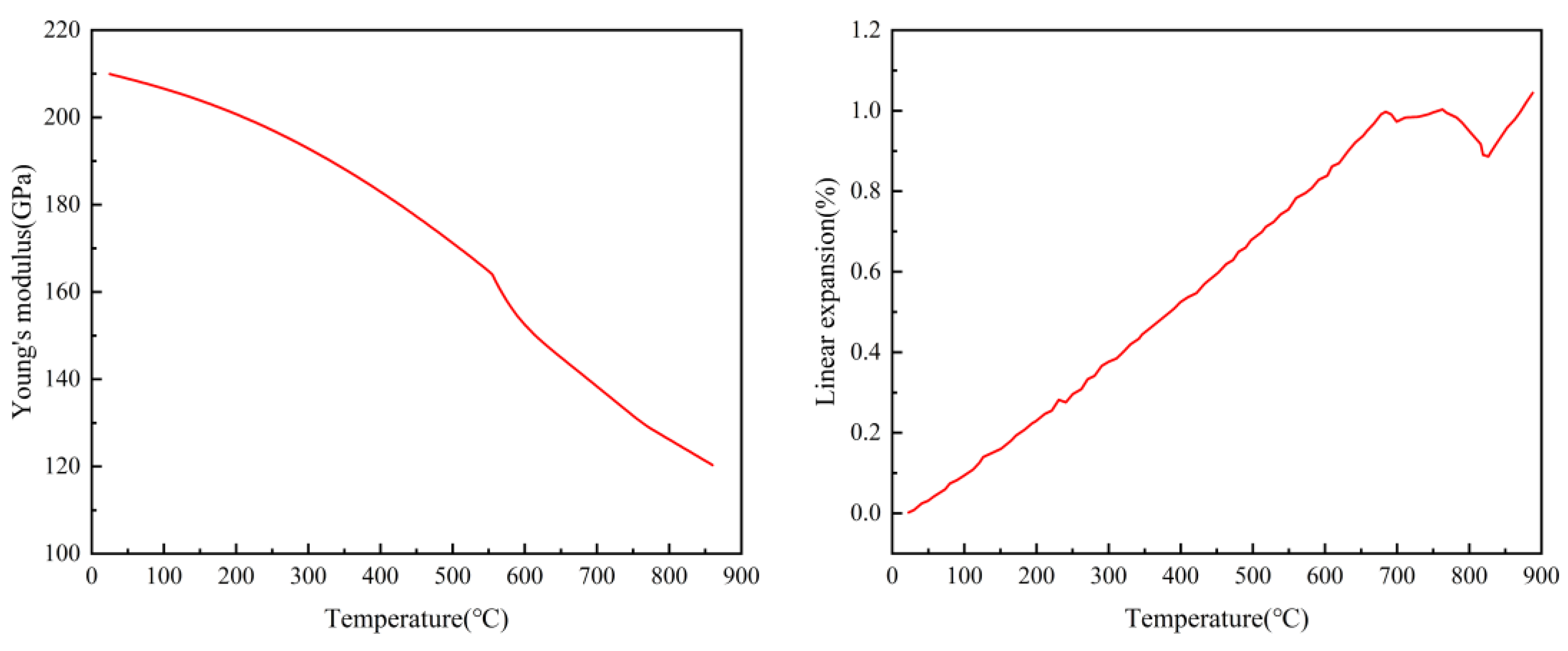
2.2. Modeling of the Temperature Field of the Quenching Process

According to the heat transfer mechanism established by the above analysis, the temperature field calculation model of the steel plate is now established.
In the steel plate surface quenching region, according to the temperature interval in which the steel plate surface cooling process is located, there are, respectively, cooling water, a gas–liquid mixture, high-temperature gas, three kinds of media, and convective heat transfer between the steel plate. As in Equations (2)~(4).
λ T T n t = h 1 T P T W ,   T P 350
λ T T n t = h 2 T P T G ,   350 < T P < 650
λ T T n t = h 3 T P T HTG ,   650 T P < 950
When the surface of the steel plate comes into contact with the cooling water, the temperature of the surface layer decreases sharply, while the rate of temperature change in the core is much smaller than that of the surface layer because it is not in direct contact with the cooling water. Due to the temperature gradient between the surface layer and the core, heat conduction takes place inside the steel plate. A Fourier three-dimensional differential equation for thermal conductivity with an internal heat source is used to describe it as follows:
x λ T T x + y λ T T y + z λ T T z = C p T ρ T t
After the steel plate passes through the roller quenching machine, the surface has almost no water residue. At this time, the convection heat transfer coefficient of thermal radiation and the natural convection heat transfer coefficient are
h a = T P 4 T a 4 T P T a ε σ 0 + 2.56 × T P T a 4
where λ T is the thermal conductivity; h 1 , h 2 and h 3 are the convective heat transfer coefficients corresponding to each temperature interval; T P , T W , T G , and T HTG are the steel plate temperature, jet temperature, water vapor mixing temperature, and high gas temperature, respectively; C P T is the specific heat capacity; ρ is the density of steel plate; t is the time; n is the direction of temperature change; T a is the surrounding air temperature; ε is the surface emissivity; and σ 0 = 5.76 × 10 8   W / m 2 · K 4 .

2.3. Modeling of the Thermal Stress Field during Quenching Process

According to the theory of thermoelastic mechanics, the material’s own gravity is ignored in the process of calculation, and the equilibrium equation, geometric equation and intrinsic equation need to be satisfied in the calculation.
The equilibrium equation is
σ x x + τ y x y + τ z x z = 0 τ x y x + σ y y + τ z y z = 0 τ x z x + τ y z y + σ z z = 0
where σ i i = x , y , z is the positive thermal stress parallel to the x , y , z coordinate axes, and τ x y , τ y z and τ x z are the tangential thermal stress.
The geometric equations is
ε x = u x x ,   γ x y = u x y + u y x ε y = u y y ,   γ y z = u y z + u z y ε z = u z z ,   γ y z = u z x + u x z
where ε x , ε y and ε z are the positive thermal strain parallel to the x , y , z coordinate axes; u is the displacement component; and γ x y , γ y z and γ z x are the tangential thermal strain.
The intrinsic equation is
ε x = 1 E σ x μ σ y + σ z + β T T 0 , γ y z = 2 1 + μ E τ y z ε y = 1 E σ y μ σ x + σ z + β T T 0 , γ x z = 2 1 + μ E τ x z ε z = 1 E σ z μ σ x + σ y + β T T 0 , γ x y = 2 1 + μ E τ x y
where E is the modulus of elasticity, μ is the Poisson’s ratio, β is the coefficient of thermal expansion of the material, T is the temperature at the current moment, and T 0 is the temperature at the previous moment.

3. Results and Discussion

Based on a large number of experiments in the field of a steel enterprise, 1+3 and 2+4 arrangement forms have been tested. Finally, the 2+4 arrangement proved to be more suitable for the quenching of medium and thick plates with variable specifications. That is, the plate passes through the quenching zone, consisting of two sets of slit nozzles and four sets of high-density nozzles in turn. It can be divided into six quench zones for the study: slit I and II regions and high-density I, II, III, and IV regions.
The study was carried out for the currently developed wide and thin-gauge wear-resistant steels with chemical compositions as shown in Table 1. JMatPro v11 is software for phase diagram calculation and material property simulation of metallic materials. With this software, the chemical composition of NM400 can be imported into the software for simulation calculations. The curves of thermal conductivity, coefficient of thermal expansion, modulus of elasticity, Poisson’s ratio, and temperature of this material are calculated as shown in Figure 5.
Numerical simulation of the quenching process was carried out using Deform v11, a finite element software with a large advantage in heat treatment. Based on the key thermophysical parameters of the steel plate obtained above, they were programmed and written into Deform v11 software to model the thermophysical properties of the material. The convective heat transfer coefficients were optimally corrected using the inverse heat transfer method based on the measured and calculated temperatures. The modified convective heat transfer coefficients are used as boundary conditions for numerical calculations to iteratively solve the steel plate temperature field. The specific calculation process is shown in Figure 6.
The solved convective heat transfer coefficient as a function of temperature is shown in Figure 7. It is programmed into the Deform v11 software as a Type III boundary condition for numerical simulation of the temperature field and stresses during the quenching process. According to the actual roller quenching machine in the quenching section of the 3500 medium-thick plate production line of a steel enterprise, the dynamic quenching finite element model of steel plate is established. The mesh structure and size have a greater impact on the calculation results. Since the current software for self-generated tetrahedral structural mesh accuracy has certain limitations, the geometry of hexahedral meshing is obtained through programming for simulation calculations. It is more in line with the actual steel plate hardening node data transfer law. In order to obtain more information in the thickness direction, the steel plate is refined in the thickness direction. The divided steel plate hexahedral unit and the quenching heat transfer region are shown in Figure 8. The nozzles of adjacent quenching regions are spaced 200 mm apart.
Table 2 shows the key process parameters used for numerical calculations.
When the transverse temperature of the steel plate is controlled to be uniform, the distribution of equivalent stresses is studied in three states: before, when, and after the steel plate passes through the quenching region of the six nozzles. Temperature and equivalent stresses were extracted at 1/2, 1/4, and the edge of the plate width for 50mm of the plate tail. The cross section of the steel plate and the location of the extraction points are shown in Figure 9.

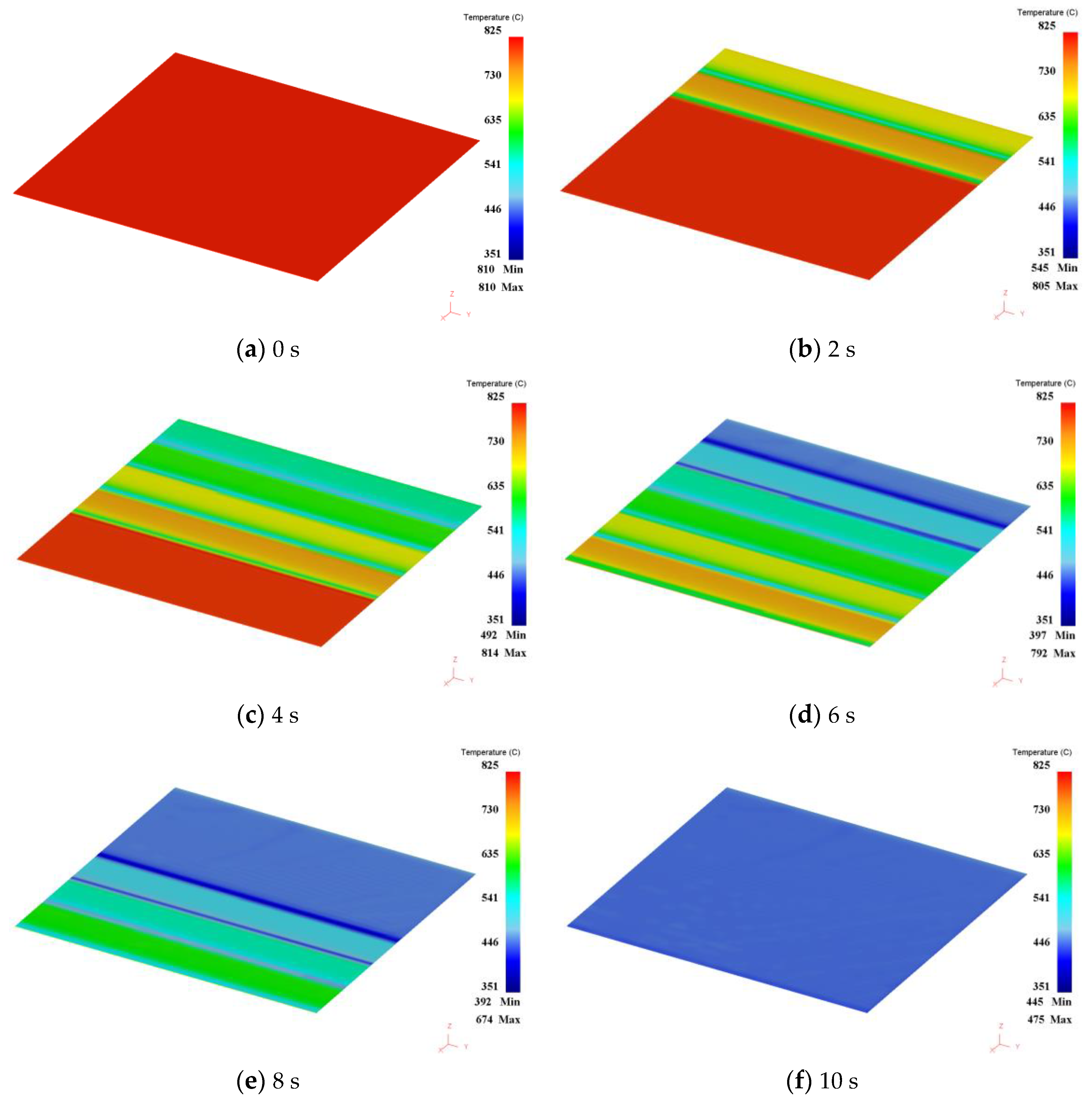
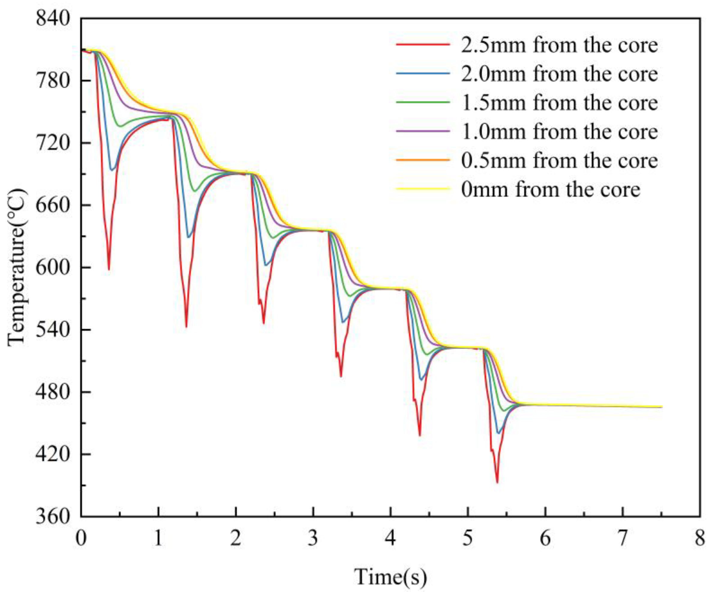
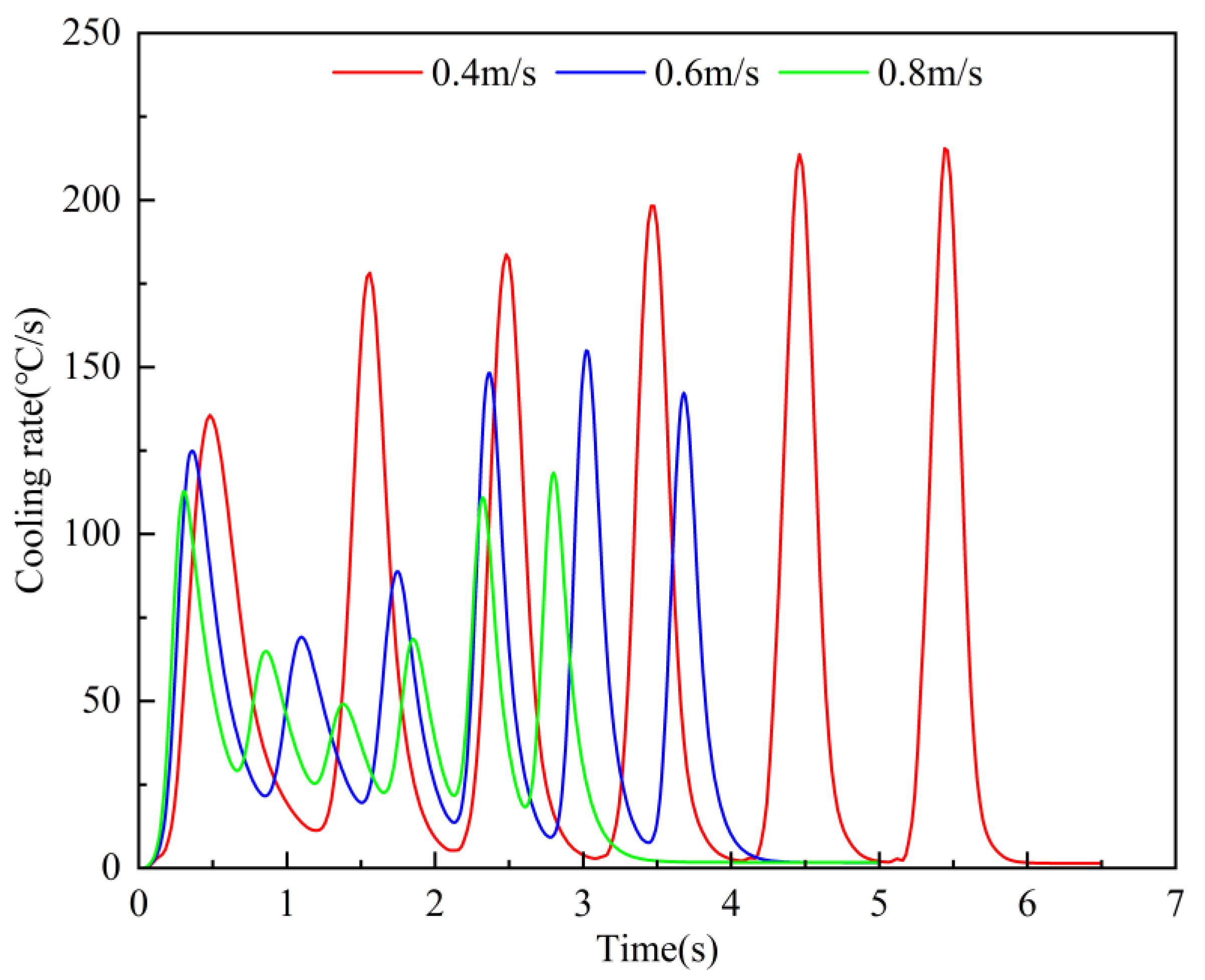
3.1. Steel Plate Temperature Field Results and Analysis

When the roller conveyor speed is 0.4 m/s, the results of the temperature field calculated for each moment of the steel plate are shown in Figure 10.
The 0 s moment is the initial moment of entering the quenching machine; the 2 s moment is when the head of the steel plate passes through two sets of slit nozzle zones; the 6 s moment is when the steel plate has passed through the high-density nozzle zone; and the 10 s moment corresponds to the steel plate leaving the roller quenching machine.
There is a significant retempering of the steel plate in the direction of the upper surface to the thickness of the core during the quenching and cooling process, as shown in Figure 11. When the steel plate passes through the first set of nozzles, the upper surface of the steel plate is rapidly cooled at a constantly changing high cooling rate, and after leaving the first set of nozzles, it is in the gap between the first and second sets of nozzles when the boundary conditions are laminar cooling. Due to the existence of a temperature gradient in the thickness direction of the steel plate, when the surface temperature of the steel plate plummets, the core is still in a transient thermal insulation condition, and then the steel plate will take the heart as a heat source to the surface of the heat conduction. When the heat transferred per unit time is greater than the heat dissipated by surface laminar cooling, the surface of the steel plate warms up briefly instead. When passing through the second set of nozzles, the temperature reached by heating is used as the base temperature to continue cooling, and the cooling is repeated in such a cycle under each set of nozzles. When passing through the slit nozzle, the average cooling rate of the steel plate surface is 588.5 °C/s, and the average cooling rate of the core is 64.8 °C/s. When passing through the high-density nozzle, the average cooling rate of the steel plate surface is 399.7 °C/s, and the average cooling rate of the core is 58.2 °C/s. The steel plate temperature is cooled to 468 °C and leaves the high-pressure quenching and cooling zone. From the above analysis, it is known that the surface temperature of the steel plate will change in the form of jagged fluctuations as it passes through each group of nozzles. As we get farther away from the surface, the temperature fluctuation gets smaller and smaller until there is no obvious fluctuation in the core. Due to the higher convective heat transfer coefficient of the slit nozzle than the high-density nozzle, the temperature fluctuation of the steel plate through the first two slit nozzles is greater than that of the last four high-density nozzles. Steel plate hardenability can be judged by the core cooling rate, so the core cooling rate was calculated separately for different roller conveyor speeds, as shown in Figure 12. The core cold velocity profile resembles the form of a wave function. It can be seen that the larger the roll speed, the smaller the overall crest of the core cold speed curve, the wave spacing of neighboring crests decreases, i.e., the wave speed increases, and at the same time, the amplitude variance of each nozzle section increases.

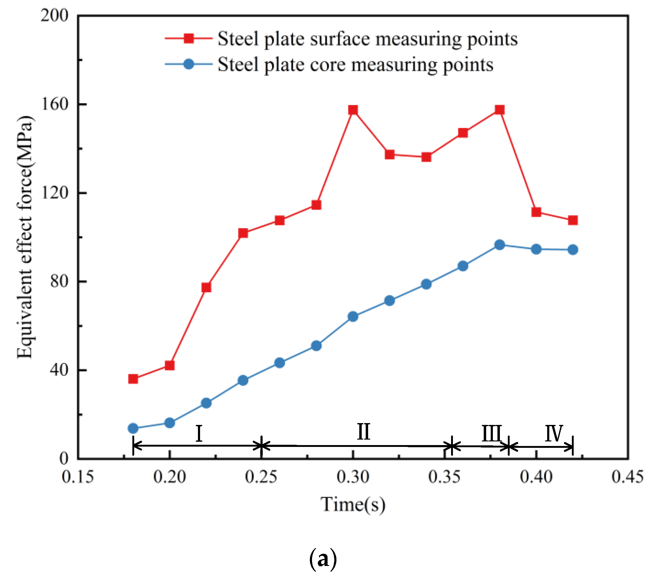
3.2. Steel Plate Stress Field Results and Analysis

An excessive cooling rate during the quenching process will lead to large quenching stresses inside the plate, so it is very important to study the stress changes in the steel plate quenching process for the control of plate shape during the quenching process. When the transverse temperature uniformity through the nozzles of each section is satisfied, the stress variations in the surface and core at this point influence the final quenched plate shape. For roller conveyor speeds of 0.4 m/s, 0.6 m/s, and 0.8 m/s, calculations of the steel plate surface measuring point and the core measuring point through each section of the quenching region when the equivalent force changes are shown in Figure 13.
The fluctuation of the temperature field of the steel plate during the quenching process affects the change in the stress field of the steel plate. When the steel plate measuring point passes through the nozzle injection area, the stress difference fluctuates as the temperature difference between the surface and core of the steel plate becomes larger, resulting in an equivalent stress difference of 10.3~93.2 MPa. Before the measurement point enters the slit nozzle, due to a certain temperature gradient in the direction of the thickness of the cooled steel plate, heat transfer occurs between the thicker measurement point and the thicker measurement point that is to enter the nozzle area. This heat transfer process leads to the formation of a temperature difference in the thickness direction of the measurement point, which gradually increases, and the equivalent force difference also gradually increases. During the entry of the measurement point into the injection region of the slit nozzle, the equivalent force difference gradually remains stable as the temperature difference increases. During the departure of the measuring point from the nozzle area, the equivalent force difference increases and then decreases. It can be seen that at the instant of leaving the nozzle, the equivalent force on the surface of the steel plate increases suddenly, while the core maintains the original growth rate, thus leading to a large difference in the equivalent force between the surface and the core. It was found that the maximum stress in the extracted nodes on the steel plate surface occurs at a moment of 0.02 s after each pass through the quenching zone. At this time, the measured steel plate node has been driven away from the nozzle by 8~16 mm. This shows that the maximum equivalent force generated when the steel plate is quenched has a hysteresis. In the nozzle area of the steel plate surface measurement point, the equivalent force is always increasing, but it will not decrease immediately after leaving the quenching area; it will continue to increase, and then the equivalent force will gradually reduce. The maximum equivalent force at the extraction point at 1/2 the thickness of the steel plate occurs at the moment of 0.15 s after each pass through the quenching zone, when the observed steel plate node has sailed away from the nozzle by 60–120 mm. It can be seen that there is a greater delay in the core than in the moment when the equivalent force appears on the surface.

4. Application of Research Results

To verify the correctness of the above research results, they were applied to on-site production. As shown in Figure 14, the wave pitch of the side waves of the steel plate before the improvement was measured to be 520 mm, and the wave height was about 5 mm. Through the optimization of the quenching process parameters and field tests, we have obtained wide and thin specification steel plate products with good plate shape, in which the unevenness of 5 mm wear-resistant steel products is ≤5 mm/m. The location of the maximum wave distance of the steel plate measured and obtained before the improvement is at the longitudinal head of the operation side, and after the improvement, the overall plate shape is obviously straight, and the measured straightness meets the standard requirements, as shown in Figure 15.
Table 3 shows the key cooling parameters for field production after several trial coolings. By adjusting the lateral distribution of cooling water flow, it ensures that the transverse temperature distribution uniformity of steel plate quenching is improved. At this time, the main influence on the plate shape is the thermal stress difference generated by the temperature gradient in the thickness direction. By adjusting the flow rate and roller conveyor speed to control the surface of the steel plate and the core cold speed, so as to regulate the temperature difference in the thick direction of the fast cooling, we can achieve quenching efficiency by improving the quenching stress generated by the quenching stress so that it does not exceed the limit.

5. Conclusions

In this study, based on the established segmented convective heat transfer model, the temperature field and equivalent stress field of wide and thin wear-resistant steel plates quenched at different roller conveyor speeds are investigated. The cooling rate and equivalent stresses are calculated and analyzed for the thick direction of the steel plate. The key findings of the study are as follows:
(1)
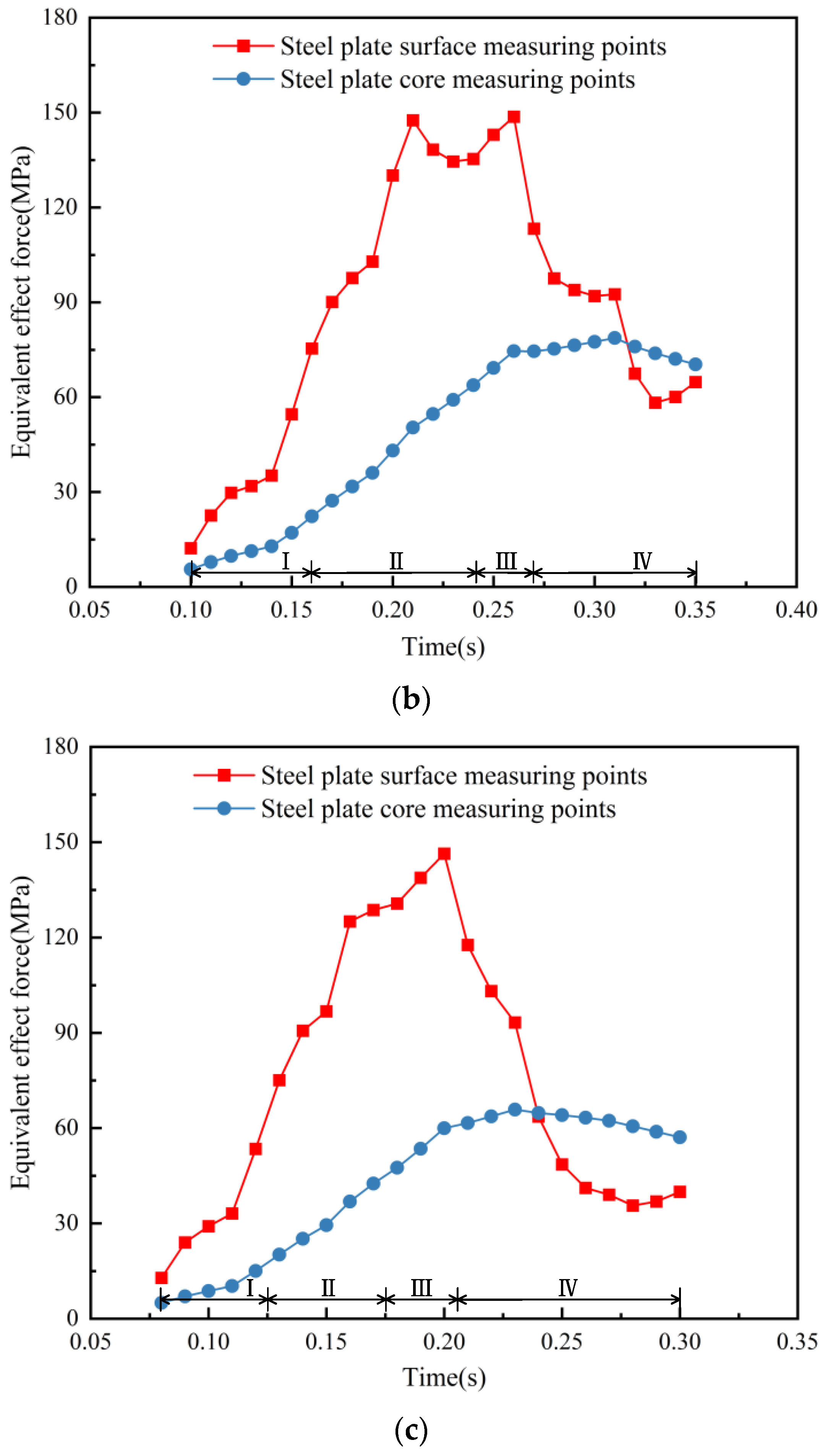
Based on the calculated equivalent force generated when passing through each nozzle region during the quenching process of the steel plate, it is concluded that the maximum equivalent force occurs during the quenching process with a hysteresis. When in the nozzle area, the equivalent force is always increasing, but not immediately after leaving the quenching area; it will continue to increase, and after a certain period of time, the equivalent force will gradually decrease again. The farther away from the surface, the more obvious the hysteresis effect.
(2)
When the roller conveyor speed is too small, the steel plate quenching area is cooled faster, and the temperature difference between the longitudinal direction and the thick direction is larger. Therefore, the steel plate core and surface equivalent force difference are larger and more prone to warping. When the roller speed is too large, the cooling speed of the steel plate is significantly reduced, and the longitudinal plate shape is better at this time. When the roller gap setting value is too small, the steel plate quenching plastic deforms and generates greater stress. At this time, the steel plate is prone to jamming and side waves. When the roller gap setting value is too large, the roller cannot play the full role of pressure. The steel plate appeared to have a serious edge wave, and the overall shape of the plate was warping. In summary, the quenching machine roll gap is closer to the incoming material thickness, and the quenching plate shape is significantly improved.
(3)
Under the premise of adjusting the relevant parameters of the quenching machine to ensure uniformity of quenching, what affects the shape of the plate after quenching is the value of the open-cooling temperature, roll speed, and roll gap. Among them, the speed of the roller conveyor directly affects the temperature drop and stress distribution of the steel plate. In this paper, based on the results of simulation calculations and on-site applications, the quenching section of the roll provides solution ideas and key parameters to ensure that the plate shape is good while improving the quenching speed as much as possible, shortening the production cycle, and improving efficiency.

Author Contributions

Conceptualization, J.W.; data curation, X.L. and S.A.E.; formal analysis, J.W. and K.Y.; methodology, X.L.; validation, K.Y., J.W. and X.L.; writing—original draft, J.W.; writing—review and editing, X.L., J.W. and S.A.E. All authors have read and agreed to the published version of the manuscript.

Funding

This research was funded by the Science and Technology Research Project of Higher Education Institutions in Hebei Province, the Major Scientific and Technological Achievements Transformation Project of Hebei Province, the Funding Project of Central Guiding for Local Science and Technology Development, the Hebei Province Science and Technology Research and Development Plan-Science and Technology Support Plan Project, and the Basic Project of Higher Education Institutions in Liaoning Province (grant numbers: CXY2023012, 22281001Z, 236Z1024G, 23280101Z, and LJKZZ20220040).

Data Availability Statement

The data presented in this study are available on request from the corresponding author. The data are not publicly available due to privacy.

Conflicts of Interest

The authors declare no conflicts of interest.

References

  1. Yuan, G.; Sun, J. Innovative practice of rolling technology under the development trend of high quality and greening. Wuhan Eng. Vocat. Tech. Coll. 2021, 38, 1–9. [Google Scholar]
  2. Fu, T.L.; Han, Y.; Deng, W.T. Development progress and application of new technology of roll quenching for high-grade steel plates. Steel Roll. 2022, 39, 60–66. [Google Scholar]
  3. Wang, Z.D.; Li, J.D.; Fu, T.L. Development and application of continuous heat treatment equipment for ultra-wide special steel plate. Steel Roll. 2019, 36, 1–5+13. [Google Scholar]
  4. Qiao, X.Y.F.; Liu, Y. Plate shape control during quenching of thin gauge steel plates. J. Iron Steel Res. 2011, 23, 159–162. [Google Scholar]
  5. Zhang, W.; Wu, M.; Du, S. Plate shape recognition based on Gaussian function and particle swarm optimization for roller quenching process. J. Process Control 2022, 119, 115–127. [Google Scholar] [CrossRef]
  6. Wu, Q.; He, S.; Hu, P. Effect of finish rolling temperature on microstructure and mechanical properties of X80 pipeline steel by on-line quenching. Mater. Sci. Eng. A 2023, 862, 144496. [Google Scholar] [CrossRef]
  7. Chen, Y.; Sun, S.; Zhang, T. Effects of post-weld heat treatment on the microstructure and mechanical properties of laser-welded NiTi/304SS joint with Ni filler. Mater. Sci. Eng. A 2020, 771, 138545. [Google Scholar] [CrossRef]
  8. Ramesh Babu, S.; Nyyssönen, T.; Jaskari, M. Observations on the relationship between crystal orientation and the level of auto-tempering in an as-quenched martensitic steel. Metals 2019, 9, 1255. [Google Scholar] [CrossRef]
  9. Tian, S.; Liu, Z.; Fu, R. Effect of Organizational Evolution on the Stress Corrosion Cracking of the Cr-Co-Ni-Mo Series of Ultra-High Strength Stainless Steel. Materials 2022, 15, 497. [Google Scholar] [CrossRef]
  10. Peng, X.; Zhang, P.; Hu, K. Simultaneous Improvement in Mechanical Properties and Fatigue Crack Propagation Resistance of Low Carbon Offshore Structural Steel EH36 by Cu–Cr Microalloying. Metals 2021, 11, 1880. [Google Scholar] [CrossRef]
  11. Shi, J.; Jiang, L.Y.; Yuan, G. Influence of ultra-fast cooling water volume ratio on the surface heat transfer of strip steel. Trans. Mater. Heat Treat. 2015, 36, 245–249. [Google Scholar]
  12. Shi, J.; Yuan, G.; Jiang, L. Numerical analysis of heat transfer intensity from twin slot vertical jet impingement on strip surface after hot rolling. J. Cent. South Univ. 2015, 22, 2816–2824. [Google Scholar] [CrossRef]
  13. Lei, K.; Gang, Z.; Ni, T. Computation of synthetic surface heat transfer coefficient of 7B50 ultra-high-strength aluminum alloy during spray quenching. Trans. Nonferrous Met. Soc. China 2018, 28, 989–997. [Google Scholar]
  14. Shi, L.; Zhu, X.; Du, Z. Experimental investigation on convective heat transfer of inclined jets impinging on the rotating cylindrical surface in the confined space. Int. J. Heat Mass Transfer. 2023, 202, 123744. [Google Scholar] [CrossRef]
  15. Yuan, G.; Zhang, R.; Zhang, Y. Heat Transfer Characteristics of a Hot-Rolled Seamless Steel Tube During a Controlled Cooling Process. Steel Res. Int. 2023, 94, 2200150. [Google Scholar] [CrossRef]
  16. Fu, Z.L.; Liu, A.Y.; Xiao, Y.L. Experimental study on heat transfer characteristics between particle flow and wall. Exp. Heat Transfer. 2023, 1–17. [Google Scholar] [CrossRef]
  17. Liu, S.; Mu, X.; Shen, S. Experimental study on the distribution of local heat transfer coefficient of falling film heat transfer outside horizontal tube. Int. J. Heat Mass Transf. 2021, 170, 121031. [Google Scholar] [CrossRef]
  18. Lobasov, A.S.; Minakov, A.V.; Rudyak, V.Y. The investigation of the velocity slip and the temperature jump effect on the heat transfer characteristics in a microchannel. Case Stud. Therm. Eng. 2022, 31, 101791. [Google Scholar] [CrossRef]
  19. Agrawal, C.; Kumar, R.; Gupta, A. Effect of jet diameter on the maximum surface heat flux during quenching of hot surface. Nucl. Eng. Des. 2013, 265, 727–736. [Google Scholar] [CrossRef]
  20. Wikström, P.; Blasiak, W.; Berntsson, F. Estimation of the transient surface temperature, heat flux and effective heat transfer coefficient of a slab in an industrial reheating furnace by using an inverse method. Steel Res. Int. 2007, 78, 63–70. [Google Scholar] [CrossRef]
  21. Zhang, Z.M.; Yu, W.; Cai, Q.W. Determination of heat transfer coefficient for roll quenching of medium-thick plate. Trans. Mater. Heat Treat. 2013, 34, 170–175. [Google Scholar]
  22. Xu, J.; Chen, G.; Bao, X. A Study on the Heat Transfer Characteristics of Steel Plate in the Matrix Laminar Cooling Process. Materials 2021, 14, 5680. [Google Scholar] [CrossRef] [PubMed]
  23. Malinowski, Z.; Telejko, T.; Hadała, B. Dedicated three dimensional numerical models for the inverse determination of the heat flux and heat transfer coefficient distributions over the metal plate surface cooled by water. Int. J. Heat Mass Transfer. 2014, 75, 347–361. [Google Scholar] [CrossRef]
  24. Karwa, N.; Gambaryan-Roisman, T.; Stephan, P. Experimental investigation of circular free-surface jet impingement quenching: Transient hydrodynamics and heat transfer. Exp. Therm. Fluid Sci. 2011, 35, 1435–1443. [Google Scholar] [CrossRef]
  25. Zou, L.; Ning, L.; Wang, X. Evaluation of interfacial heat transfer coefficient based on the experiment and numerical simulation in the air-cooling process. Heat Mass Transf. 2022, 58, 337–354. [Google Scholar] [CrossRef]
  26. Zhang, Z.M.; Yu, W.; Cai, Q.W. Control Basis for Cooling Rate of Plates during Roller Quenching in High-Pressure Zone. Adv. Mater. Res. 2012, 538, 2090–2094. [Google Scholar] [CrossRef]
  27. Yuan, G.; Han, Y.; Wang, C. Cooling mechanism of quenching process of roll quenching machine for medium-thick plate. Trans. Mater. Heat Treat. 2010, 31, 148–152. [Google Scholar]
  28. Wang, C.; Wang, Z.; Yuan, G. Heat transfer during quenching by plate roller quenching machine. J. Iron Steel Res. Int. 2013, 20, 1–5. [Google Scholar] [CrossRef]
  29. Zhang, J.K.; Zhang, R.M.; Chen, Y.Y. Temperature field simulation of quenching and cooling process of roll quenching machine. Heat Treat. Met. 2011, 36, 85–88. [Google Scholar]
  30. Wang, X.Y.; Su, H.; Pan, T. ANSYS finite element simulation of the effect of surface cooling velocity on the temperature field of ultra-thick plate section. Mater. Sci. Technol. 2013, 21, 49–54. [Google Scholar]
  31. Cui, D.; Liang, H. Numerical simulation on quenching temperature field of 40Cr steel. Adv. Mater. Res. 2011, 154, 417–420. [Google Scholar] [CrossRef]
  32. Carlone, P.; Palazzo, G.S.; Pasquino, R. Finite element analysis of the steel quenching process: Temperature field and solid–solid phase change. Comput. Math. Appl. 2010, 59, 585–594. [Google Scholar] [CrossRef]
  33. Xie, Q.; Wang, Y.; Li, X. Two-dimensional transient heat transfer model of moving quenching jet based on machine learning. Int. J. Heat Mass Transf. 2022, 191, 122765. [Google Scholar] [CrossRef]
  34. Li, C.; Yu, H.; Deng, G. Numerical simulation of temperature field and thermal stress field of work roll during hot strip rolling. J. Iron Steel Res. Int. 2007, 14, 18–21. [Google Scholar] [CrossRef]
  35. Yuan, G.; Wang, G.D.; Wang, L.J. Temperature field analysis of quenching process in roll quenching machine for medium-thick plate. J. Northeast. Univ. (Nat. Sci.) 2010, 31, 527–530+538. [Google Scholar]
  36. Agrawal, C. Surface quenching by jet impingement—A review. Steel Res. Int. 2019, 90, 1800285. [Google Scholar] [CrossRef]
  37. Tong, C.N.; Gao, Y.D. A practical method for modeling heat transfer coefficients of water-cooled processes in steel plates. Iron Steel 2011, 46, 50–55. [Google Scholar]
Figure 1. Roll quenching process.
Metals 14 00083 g001
Figure 2. The relationship between convective heat transfer coefficient and quenching capacity.
Metals 14 00083 g002
Figure 3. The droplets vaporize on the surface of the high-temperature steel plate.
Metals 14 00083 g003
Figure 4. Jet structure and heat transfer area distribution.
Metals 14 00083 g004
Figure 5. NM400 thermophysical parameters as a function of temperature.
Metals 14 00083 g005aMetals 14 00083 g005b
Figure 6. Convective heat transfer coefficient optimization and temperature field distribution solution process.
Metals 14 00083 g006
Figure 7. Convective heat transfer coefficient as a function of temperature.
Metals 14 00083 g007
Figure 8. Steel plate meshing and quenching heat exchange area arrangement.
Metals 14 00083 g008
Figure 9. Steel plate cross-section and extraction node position.
Metals 14 00083 g009
Figure 10. Temperature field distribution of steel plate in the quenching process.
Metals 14 00083 g010
Figure 11. Temperature drop curve of the thick aliquot measurement point of the steel plate head.
Metals 14 00083 g011
Figure 12. Cooling rate curve of steel plate core.
Metals 14 00083 g012
Figure 13. Dynamics of equivalent stresses in the plate thickness toward the measuring point through the quenching region. I—Before entering the nozzle area; II—Located in the nozzle area; III—Initial departure from the nozzle area; IV—Keep away from the nozzle area. (a) Roller conveyor speed of 0.4 m/s. (b) Roller conveyor speed of 0.6 m/s. (c) Roller conveyor speed of 0.8 m/s.
Metals 14 00083 g013aMetals 14 00083 g013b
Figure 14. Plate shape measurement after quenching the 5 mm steel plate.
Metals 14 00083 g014
Figure 15. Comparison of outlet plate shape before and after adjusting quenching parameters. (a) Before improvement, (b) improved.
Metals 14 00083 g015aMetals 14 00083 g015b
Table 1. NM400 main chemical composition.
ElementalCSiMnPSTiCuNiCrFe
mass percent %0.1450.2991.4240.0090.000350.0150.01590.01170.694bal
Table 2. Numerical calculation of key process parameters.
Steel Plate ParametersCooling Process ParametersRoller Conveyor Speed (m/s)
Thicknesses/mm5Cooling water temperature/°C220.4
Width/mm2600Jet pressure/MPa0.80.6
Minimum grid size/mm0.25Open-cooling temperature/°C8100.8
Table 3. Critical cooling parameters for on-site production.
Steel Plate and Roller Conveyor InformationKey Cooling Information
Thickness/mm5Slit nozzle flow/(m3/h)500
Width/mm2600High-density nozzle flow/(m3/h)160
Open cold temperature/°C810Cooling water temperature/°C22
Roll seam setting/mm5.05Jet pressure/MPa0.8
Roller conveyor speed/(m/s)0.8Upper and lower water ratio settings1.28
Disclaimer/Publisher’s Note: The statements, opinions and data contained in all publications are solely those of the individual author(s) and contributor(s) and not of MDPI and/or the editor(s). MDPI and/or the editor(s) disclaim responsibility for any injury to people or property resulting from any ideas, methods, instructions or products referred to in the content.

