Article

Evaluating the Effect of Blended and Pure Hydrogen in X60 Pipeline Steel for Low-Pressure Transmission Using Hollow-Specimen Slow-Strain-Rate Tensile Testing

by
Rashiga Walallawita
1,*,
Matthew C. Hinchliff
1,
Dimitry Sediako
1,*,
John Quinn
2,
Vincent Chou
2,
Kim Walker
2 and
Matthew Hill
2
1
High-Performance Powertrain Materials Laboratory, University of British Columbia, 1137 Alumni Ave, Kelowna, BC V1V 1V7, Canada
2
FortisBC, 16705 Fraser Hwy, Surrey, BC V4N 0E8, Canada
*
Authors to whom correspondence should be addressed.
Metals 2024, 14(10), 1132; https://doi.org/10.3390/met14101132
Submission received: 16 August 2024 / Revised: 30 September 2024 / Accepted: 2 October 2024 / Published: 4 October 2024
(This article belongs to the Special Issue Hydrogen Embrittlement of Metals and Alloys)

Abstract

:
This study employs a custom hollow specimen setup to investigate the HE in API 5L X60 pipeline base and welded materials exposed to pure hydrogen and a 20% hydrogen–natural gas blend at 2.07 MPa. Results indicate embrittlement with increasing hydrogen concentration. The base material showed a hydrogen embrittlement index (HEI) of 11.6% at 20% hydrogen and 12.4% at 100% hydrogen. For the welded material, the HEI was 14.6% at 20% hydrogen and 18.0% at 100% hydrogen. Fractography analysis revealed that the base and welded materials exhibited typical ductile fracture features in the absence of hydrogen, transitioning to a mixture of quasi-cleavage and micro-void coalescence (MVC) features in hydrogen environments. Additionally, with hydrogen, increased formation of secondary cracks was observed. Notably, the study identified the Hydrogen-Enhanced Localized Plasticity (HELP) mechanism as a probable contributor to hydrogen-assisted fracture.

1. Introduction

Hydrogen has been proposed as a promising form of renewable energy to decarbonize the energy sector. To initiate the large-scale distribution of hydrogen gas, it is both time- and resource-efficient to utilize the existing natural gas pipeline networks. At first, hydrogen will be blended at lower concentrations with natural gas before eventually increasing up to 100% hydrogen. Transporting hydrogen through the existing pipeline network presents an inherent challenge due to hydrogen’s small molecular size, which allows it to diffuse easily into metallic materials. Once hydrogen diffuses into a material, it can reduce the material’s ductility and/or strength, a phenomenon known as hydrogen embrittlement (HE). The extent to which a material is susceptible to HE is mainly dependent on material composition and microstructure. Pipelines, typically manufactured using ferritic steels, are particularly vulnerable to this effect. Given the importance of this issue, existing natural gas pipelines must undergo rigorous testing prior to use in hydrogen applications. This necessity has created numerous research initiatives aimed at understanding and mitigating the effects of HE on pipeline materials.
The hydrogen embrittlement process can broadly be categorized into three steps: first, hydrogen is adsorbed onto and absorbed into the material; second, hydrogen diffuses and becomes trapped at specific sites within the material; and finally, this leads to cracking or hydrogen-induced damage with sufficient hydrogen accumulation and/or stress conditions. The research article by Li et al. [1] provides a detailed overview of this process. To explain the cracking or hydrogen damage process, researchers have proposed several HE mechanisms, including the Hydrogen Pressure Theory (HPT) [2], Hydrogen-Induced Phase Transformation (HIP), Hydrogen-Enhanced Decohesion (HEDE) [3], Hydrogen-Enhanced Localized Plasticity (HELP) [4] and Adsorption-Induced Dislocation Emission (AIDE). However, the objective of this paper is not to delve into these mechanisms in detail. For comprehensive discussions on these mechanisms, please refer to the research articles cited here [1,5,6,7,8,9].
A slow-strain-rate tensile test often serves as a pre-screening method for evaluating HE in different materials [10]. Several test setups are available for conducting slow-strain-rate tensile tests. Among them, in situ autoclave testing stands out as a standard method, as outlined in ASTM G142 [11] and ISO 11114-4 [12]. However, developing or acquiring an autoclave test setup requires substantial investment in time, resources, and adherence to strict safety protocols, therefore posing significant challenges. To address these challenges, researchers have adopted safer and more efficient testing methods. One increasingly popular approach involves using hollow specimens. This setup employs a cylindrical specimen that features a blind or through-hole centered along the tensile axis, which can be pressurized with a gas of interest. While differences exist in the degree of embrittlement measured between the hollow and autoclave testing setups [13], the authors argue that the hollow specimen setup offers a more accessible approach for conducting in situ HE testing and research. The broader adoption of such test setups could pave the way for standardizing the use of hollow specimens.
Boot et al. incorporated the hollow specimen setup [14], citing Chandler and Walter, who first reported this testing approach in 1974 [15]. Rahimi et al. utilized this method to perform slow-strain-rate tests on API 5L X65 pipeline steel with acoustic emission monitoring at 1 MPa and 10 MPa pressures, identifying three fracture event clusters [16].
Konert et al. employed micro-computed tomography (CT) imaging on API 5L X65 pipeline steel subjected to slow-strain-rate tensile tests [17]. The researchers concluded that exposure to hydrogen significantly increased the number of secondary cracks and altered crack orientation, with the primary crack propagating orthogonally to the tensile load and asymmetrically around the inner hole. In a related study, the same researchers found that a drilled surface, which generated higher roughness, led to greater susceptibility to hydrogen embrittlement [18]. Campari et al. used the same setup to compare vintage and modern X65 pipeline steel.
Michler et al. compared in situ hollow specimen and autoclave testing setups, reporting higher embrittlement indices with the autoclave setup. They recommended further optimization of specimen geometry to align the results of both methods [13]. In another study, Michler et al. investigated in situ and thermally pre-charged ex situ testing of stainless steel samples [19]. They found that both yield strength and ultimate tensile strength were comparable across test conditions, and the thermally pre-charged specimens had a similar reduction in the area. The hollow specimens showed a lower reduction in area compared to the conventional autoclave specimens in an inert atmosphere. However, while exposed to hydrogen gas, the hollow specimens exhibited a greater reduction in area compared to conventional specimens. Additionally, Ogata et al. extensively characterized various stainless steels in hydrogen, examining the impacts of temperature and hole surface roughness across multiple studies [20,21,22,23,24,25]. The studies were conducted at low (20 K) and high (800 K) temperatures and were more efficient and economical than a conventional autoclave setup. Wire-cut machining was cost-effective for machining the internal hole and provided a sufficient surface finish. The 304 stainless steel showed the highest embrittlement, and 316L was the most resistant based on slow-strain-rate and fatigue tests. Embrittlement increased with decreasing temperature, particularly around 190 K, but diminished significantly at temperatures below 120 K.
This study focuses on adapting a “hollow specimen setup” to investigate the effects of pure hydrogen and blended hydrogen (20%) with natural gas at a total pressure of 2.07 MPa (300 psi) on commercially available API 5L X60 pipeline base and welded materials. This pressure was chosen to reflect the lower natural gas transmission pressures used in British Columbia, Canada.

2. Experimental Procedure

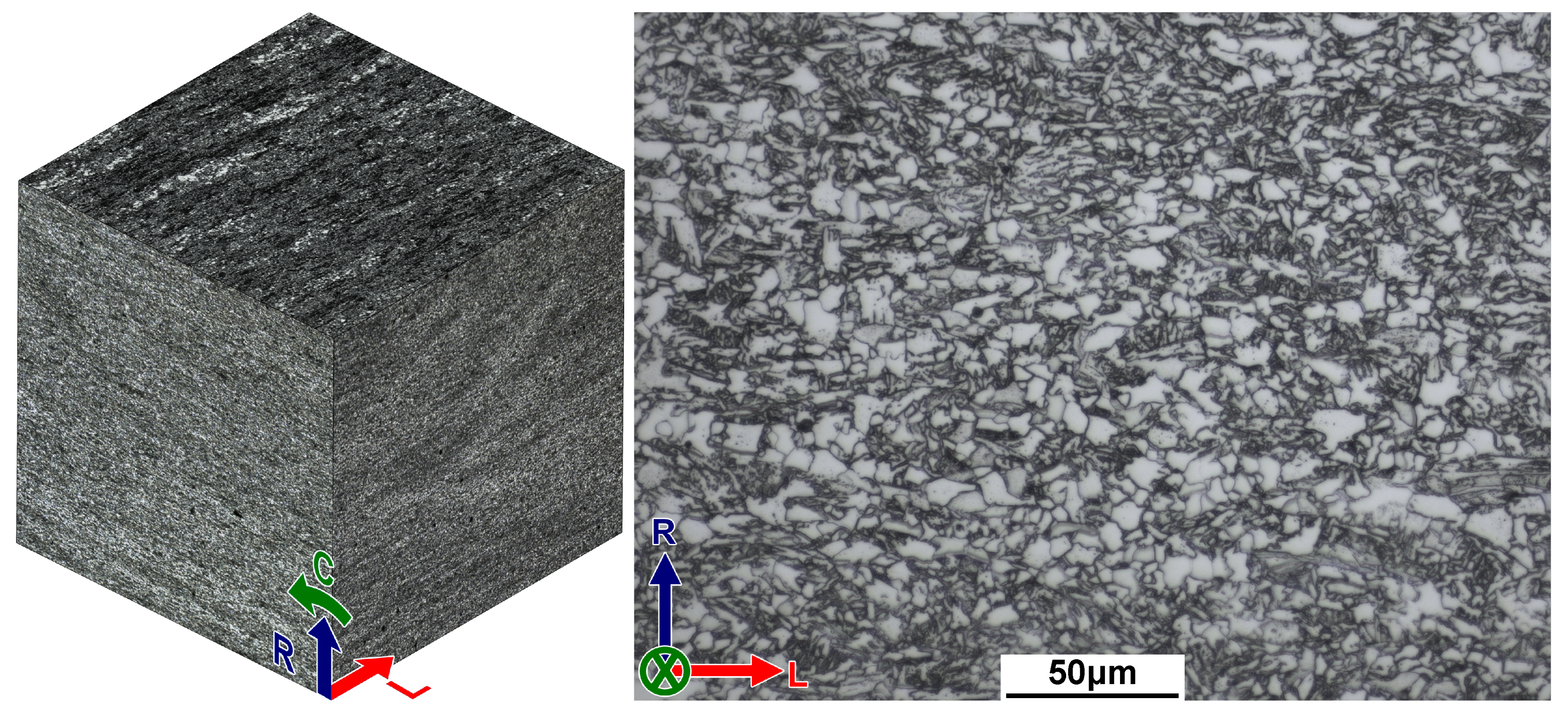
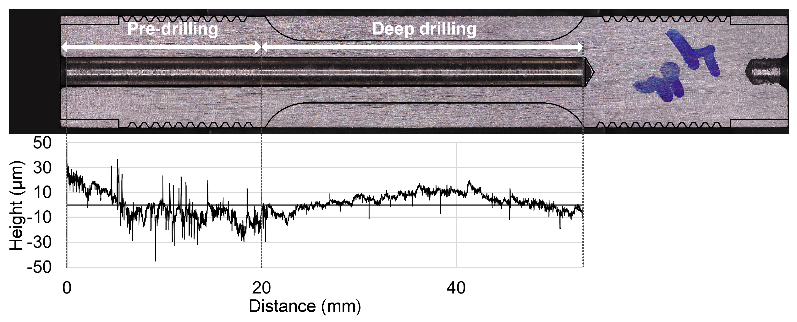
2.1. Material and Sample Preparation

Materials from the base metal and seam weld of a commercial API 5L X60 pipe section, which had not been in service, were utilized for this study. The pipe dimensions included an outer diameter of 762 mm (30 inches) and a wall thickness of 19.1 mm. The chemical compositions of the base metal and the welded material were analyzed using Bruker Q4 Tasman Spark OES, with a summary of results provided in Table 1. The mechanical properties of the base metal and welded material extracted from the supplier’s material test report are listed in Table 2.
Optical microscopy was employed for microstructural characterization. The polished samples from both the base and welded regions were etched with a 5% Nital solution to reveal their microstructure. The micrographs presented in Figure 1 depict the base metal, oriented perpendicular to the pipe’s longitudinal (L), radial (R), and circumferential (C) directions. The base metal microstructure consists of a mixture of ferrite, pearlite, and cementite. As reported by Michler et al., for API 5L X60 pipeline steel, cementite particles were observed within the ferrite grains [13]. The microstructure exhibits banding induced during the manufacturing process, with elongated layers of ferrite and pearlite aligned with the rolling direction. For thicker-walled pipelines, a similar layered microstructure is typically observed [26]. The microstructure of the weld fusion zone (WFZ) consists of secondary Widmanstätten ferrite and acicular ferrite microstructure (Figure 2b). In the heat-affected zone (HAZ), bainite, pearlite, and cementite were observed (Figure 2c).
Vickers hardness measurements were conducted along the weld and base material, following the ASTM E92 standard [27], using a 10 kg load applied for 10 s. Indentations were spaced 1.175 mm apart. The Vickers hardness of the base metal and welded material was measured as 202.6 ± 0.4 and 214.2 ± 2.8 HV, respectively. Additionally, hardness was measured across the cross-section of the weld (Figure 2d). The base metal surrounding the weld (∼170–180 Hv) exhibited lower hardness compared to the base metal, likely due to an unintended annealing effect induced by the welding process.
The base and welded material specimens were extracted, as illustrated in Figure 3a,b. The specimen from the base metal (Figure 3a) was oriented with the gauge section along the longitudinal axis. For the welded material (Figure 3b), the specimens were extracted in such a way that the weld was in the middle of the gauge section along the circumferential direction.
The dimensions of the hollow specimens are shown in Figure 3c. A 3.175 mm (1/8 inch) extended drill bit was used to create the internal hole, with the depth set to extend through the gauge section of the specimen. Deep drilling was performed using an HAAS UMC 750 5-axis milling machine (Haas Automation Inc., Oxnard, CA, USA) to ensure concentricity and repeatable surface roughness. First, an uncoated high-speed steel (HSS) drill bit, similar to the final hole diameter, was used for pre-drilling. Afterwards, deep drilling was performed using an extended high-speed steel (HSS) drill bit. Both uncoated and titanium nitride (TiN)-coated extended high-speed steel (HSS) drill bits were tested for deep drilling. The TiN-coated drill bit was selected due to its improved surface finish and better chip evacuation. The pre-drill and deep drilling depths were selected to ensure that the inner surface was consistent within the gauge section of the specimen. Prior to testing, the specimens were cleaned in an ultrasonic bath with 99% isopropyl alcohol to remove coolant traces and other impurities. They were then stored in a low-humidity environment.
After each drilling operation, the drill bit tips were examined for wear and replaced as needed. Before machining the outer profiles of the cylindrical tensile specimens, the roughness of the deep-drilled surface was assessed using a cross-section from a drilled cylinder taken from the pipe section. The surface roughness was measured as an average of five line roughness measurements using a Keyence VR-6000 optical profilometer (Keyence Corporation, Osaka, Japan). Figure 4 below shows the obtained roughness profiles, with an average roughness (Ra) of 5.8 µm. Notably, the region pre-drilled using an uncoated drill bit exhibited a higher surface roughness than the region that was deep-drilled using the TiN-coated drill bit.

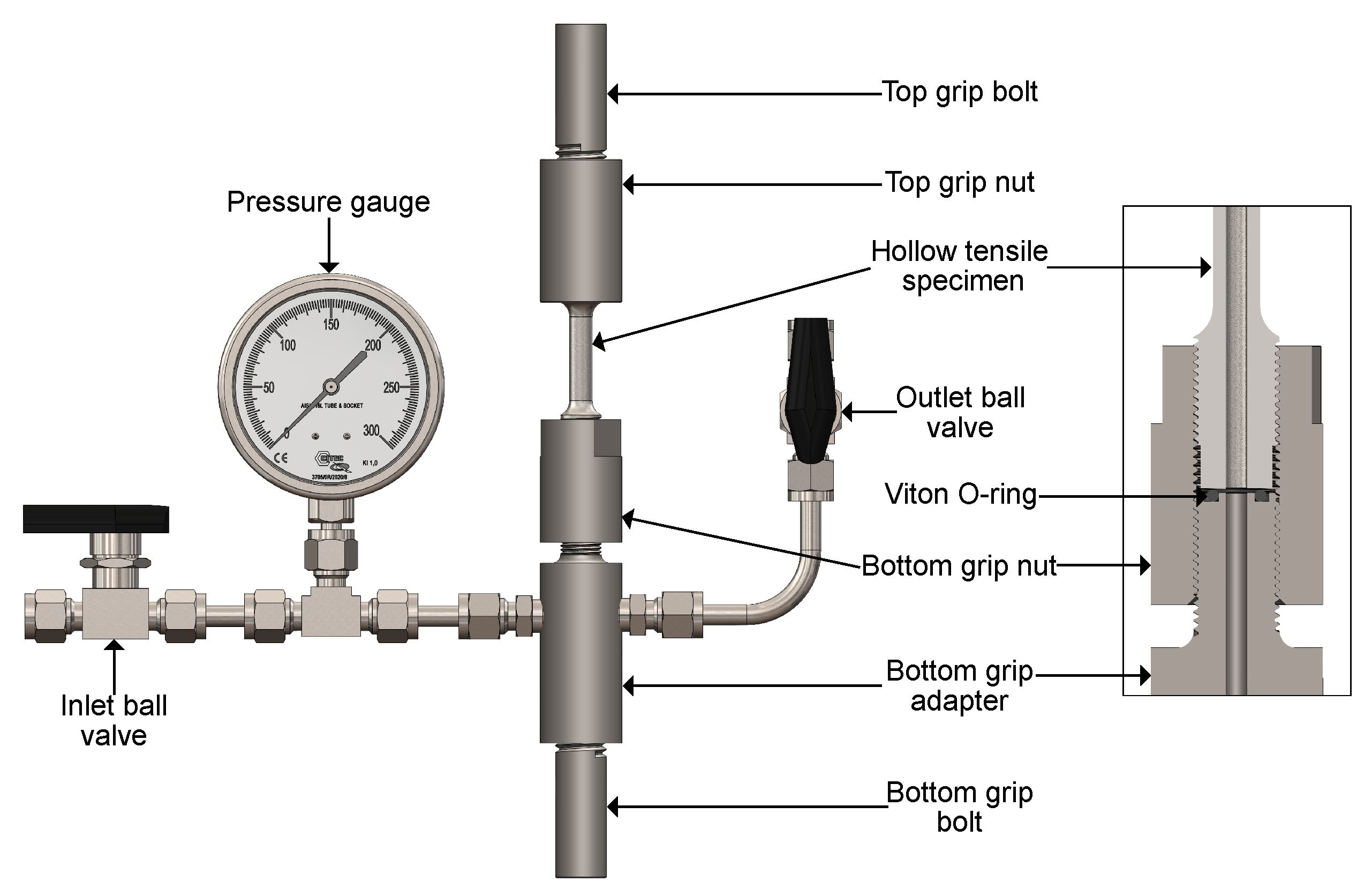
2.2. Test Setup and Environment

The hollow specimen setup was inspired by a design developed by Boot et al. [14] and adapted for easier integration with the gripping system of an existing load frame. A hydrogen-compatible Viton O-ring was used to establish the seal between the hollow specimen and the grip system. The shank section of the hollow specimen was designed to restrict movement through the “bottom grip nut”, ensuring secure sealing of the specimen. The sealing surface of the specimen was faced and ground to create a flat, smooth finish, ensuring optimal mating with the O-ring and minimizing the risk of gas leaks during testing. Figure 5 illustrates the hollow specimen setup used in this study.
A custom-designed Gas Management System (GMS) was employed to pressurize the testing setups used for HE studies. The GMS facilitated the purging, vacuum evacuation, and charging of the test setup, ensuring the purity of the test environment. Prior to testing, the test setup underwent three purging cycles with nitrogen (purity grade 5.0), with each cycle followed by vacuum evacuation. For tests conducted with pure hydrogen, after three nitrogen purge cycles, the GMS was purged with hydrogen (purity grade 5.0), vacuum evacuated, and then filled to the final test pressure. In the tests involving a 20% hydrogen mixture, the desired ratio was achieved using Dalton’s law of partial pressures (Equation (1)). Deviations from ideal gas behaviour were considered negligible, given that the mixing was performed at room temperature and a total pressure of 2.07 MPa (300 psi). After completing the nitrogen purge cycles, hydrogen was first introduced at 0.41 MPa (60 psi), followed by the addition of methane (purity grade 3.7) at a higher pressure (above 0.41 MPa) to achieve a total pressure of 2.07 MPa. The gas volume remained constant during mixing, and pressure was monitored using a high-precision digital gauge for accuracy. Reference tests were conducted using methane. For the base and welded materials, three specimens were tested with different hydrogen concentrations. However, only two specimens were tested for the welded material with 20% hydrogen concentration.
P H 2 + P CH 4 = P Total

2.3. Test Procedure

After pressurizing with the gas of interest, the ball valves surrounding the hollow specimen setup were closed to isolate the gas volume. This setup was then inspected for leaks using an Inficon GAS-Mate Combustible Gas Leak detector (718-202-G1, INFICON, Bad Ragaz, Switzerland). Once verified, the hollow specimen setup was detached from the GMS and securely mounted within the hydraulic grips of an MTS 100 kN servo-hydraulic load frame. To ensure there were no leaks, the setup was kept undisturbed for one hour before testing commenced. Each test was conducted at a constant displacement rate of 3 × 10⁻⁴ mm·s−1, which corresponds to a theoretical strain rate of 1.2 × 10⁻⁵ s−1. Throughout each test, both the force output and crosshead displacement were continuously recorded.
The HEI serves as a quantifiable metric to evaluate the degree of HE in a material based on the observed reduction in its ductility. Changes in ductility can be quantified by measuring the Elongation at Fracture (EF) and the Relative Reduction in Area (RRA) of samples’ gauge sections, both with and without hydrogen exposure. In this study, RRA measurements were used to calculate the HEI index, as shown in Equations (3) and (4). Additionally, EF was calculated using Equation (2). The fracture surface area of each specimen was measured using a Keyence VR 6000 3D optical profilometer (Keyence Corporation, Osaka, Japan). Fractography was conducted using a Tescan Mira 3 XMU scanning electron microscope (TESCAN, Brno, Czech Republic) while optical microscopy was completed using a Zeiss Axio Observer optical microscope (Carl Zeiss AG, Jena, Germany).
EF = Final gauge length ( L o ) Initial gauge length ( L i ) Initial gauge length ( L i ) × 100
RRA = Cross section before testing ( A i ) Cross section after testing ( A f ) Cross section before testing ( A i ) × 100
HEI % = RRA air , CH 4 RRA HENG , H 2 RRA air , CH 4 × 100

3. Results and Discussion

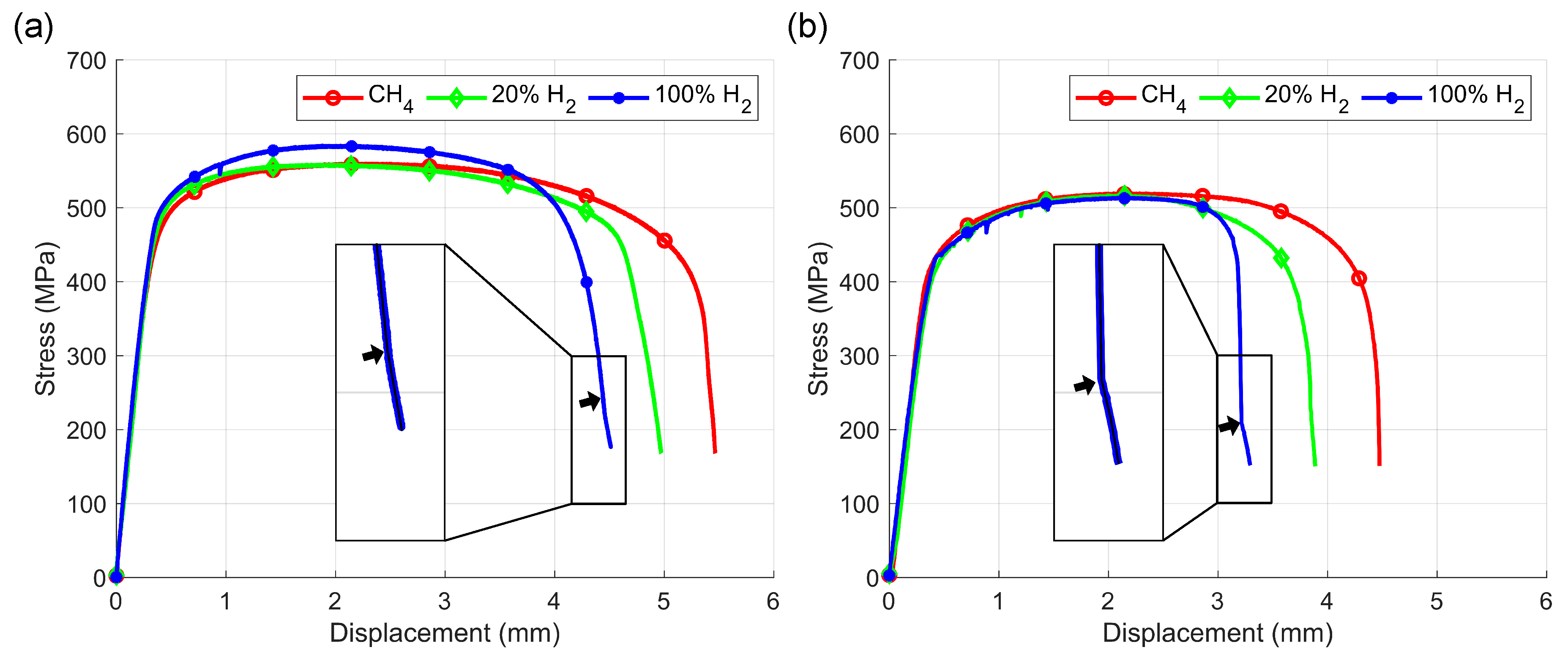
3.1. Slow-Strain-Rate Test Results

Figure 6 compares stress vs. displacement curves for specimens tested in 0, 20, and 100% hydrogen. For clarity, each test condition is represented by a single stress–displacement curve. A wide variation in displacement was observed across the tests.
As reported by many researchers [28,29,30,31], hydrogen exposure did not significantly affect the yield and tensile strength of the base and welded materials. While some deviation in the tensile strength was observed, all samples fell within the strength range specified in the material test report. All the stress–displacement curves show similar behaviour up to the ultimate tensile strength threshold. However, after necking began, the influence of hydrogen became evident, highlighting the impact of stress-induced hydrogen diffusion.
Konert et al. utilized a hollow specimen setup to conduct slow-strain tests and noted a distinctive “knee point” in the force vs. displacement output when testing samples were exposed to hydrogen [17]. This “knee point” divides the force–displacement curve into two distinct regions: (1) before the “knee point”, where more brittle behaviour is observed, and (2) after it, where there is a noticeable shift towards more ductile behaviour. They hypothesized that the “knee point” represents when a crack first reaches the outer surface of the specimen, releasing the pressurized gas. To confirm this hypothesis, the pressure within the hollow specimen setup was monitored alongside the force and displacement outputs. Tests conducted with hydrogen exhibited a similar “knee point”, as described by Konert et al. Upon reaching the “knee point”, the system’s pressure dropped to zero, which indicated that an internal crack had indeed reached the outer surface of the specimen. This initiated a shift towards more ductile behaviour in the force–displacement curve. A Supplementary Video (Video S1) is attached to this work, indicating the pressure drop at the “knee point”.
Moreover, at the knee point, hydrogen is released from the test environment, and these stress vs. displacement curves indicate the behaviour switching from brittle to ductile. This phenomenon can be argued to be the degree of reversibility of pipeline steel after hydrogen escapes from the test environment. This signifies the importance of conducting gaseous in situ testing for pipeline steels. Figure 7 summarizes the results from slow-strain-rate tensile tests for the base and welded materials. The results reveal that the base material (Figure 7a) maintains relatively stable ductility above 20% hydrogen concentration after some reduction in EF and RRA when the hydrogen concentration is increased above 0%. Specifically, the base material’s EF decreased from 24.2% at 0% hydrogen to about 21% in both cases of 20% and 100% hydrogen. At the same time, its RRA decreased from 74.9% at 0% hydrogen to about 66% with the presence of hydrogen (both for 20% and 100% hydrogen concentrations). Comparing the relative difference between EF and RRA changes with hydrogen concentration from 20% to 100%, even 20% hydrogen can significantly impact ductility. Reflecting the changes in the RRA, the HEI index for 20 and 100% percentage hydrogen exposure were 11.6 and 12.4%.
The EF for the welded material (Figure 7b) decreased from 17.0% at 0% hydrogen to about 13% at 20% and 100% hydrogen. Similar to the base metal, the welded material’s EF had a similar pattern moving from 0, 20 to 100% hydrogen. Unlike the base metal, the RRA for the welded material decreased more significantly from 71.9% at 0% hydrogen to 58.9% at 100% hydrogen. However, the RRA for the welded material had a higher error than the base material. The HEI for the welded material increased from 14.6% at 20% hydrogen to 18.0% at 100% hydrogen, indicating greater susceptibility to hydrogen embrittlement compared to the base material.
Compared to the base material, the welded material’s HAZ and the surrounding base metal have a lower hardness. This soft microstructure will result in relatively high localized plastic strain compared to the base metal, resulting in relatively high hydrogen diffusion. Therefore, the welded material showed higher HEI than the base metal.

3.2. Fractography Analysis

The base metal exposed to methane (Figure 8a) exhibited a typical ductile fracture characterized by micro-void coalescence (MVC) [32]. Upon closer examination, equiaxed dimples (Figure 8b) were observed predominantly along the center of the cross-section. In contrast, parabolic dimples (Figure 8c) were observed near the inner and outer surfaces. Additionally, the fracture surface exhibited an elliptical shape, attributed to the anisotropy caused by the banded microstructure along the rolling direction, similar to the results reported in [13].
When exposed to blended or pure hydrogen (Figure 8d,g), hydrogen-assisted fracture (HAF) regions can spread outwards from the inner surface. These regions typically consist of quasi-cleavage (QC)-like features closer to the inner surface (Figure 8e,h). Further moving outwards, a transition region can be observed with a mixture of QC and equiaxed dimples (Figure 8f,j). The remainder of the cross-section displayed parabolic dimples, indicative of MVC (Figure 8k). In contrast to the base metal exposed to methane, the hydrogen-exposed samples showed more pronounced cracks forming at the inner surface near the fracture zone, identified as secondary cracks. The drilling process can introduce micro-scratches on the inner surface, creating local stress concentrations when necking occurs. These stress concentrations facilitate localized hydrogen diffusion, leading to the formation of both primary and secondary cracks. The presence of QC fracture features on the secondary cracks further supported this observation (Figure 8i).
Boot et al. also noted similar secondary cracks forming and cited several other instances of these cracks occurring [14]. To mitigate this, they proposed that careful surface preparation could limit the impact of machining defects. Similar to the approach with a notched specimen outlined in ASTM G142 [11], employing a hollow specimen with an internal sharp notch introduces a single point of stress concentration. This concentrated stress point could reduce the formation of secondary cracks by focusing stress in one area.
The welded material showed fracture characteristics similar to those of the base metal. When exposed to methane, MVC can be observed in the equiaxed and parabolic dimple regions (Figure 9a–c). However, compared to the base metal, the equiaxed dimple region occupies a larger fracture surface area.
When exposed to hydrogen, regions of HAF and MVC can be observed (Figure 9d). Similar to the base metal, the majority of the HAF region consists of the QC fracture region (Figure 9e) and a transition region, with QC and MVC similar to the base metal exposed to hydrogen. The secondary cracks also exhibited QC fracture (Figure 9f), indicating hydrogen-induced crack growth.
To identify the fracture location along the gauge section of a welded material sample, a cross-section perpendicular to the fracture surface was examined using an optical microscope (Figure 10a,d). The fracture locations of both the methane and hydrogen-exposed samples were found between the heat-affected zone (HAZ) and the base metal. This area exhibited the lowest hardness, indicating lower yield and tensile strength. Consequently, this region is more likely to undergo plastic deformation before the other regions of the material, leading to localized necking, stress-induced hydrogen diffusion, and, ultimately, failure.
A closer examination of the microstructure (Figure 10b,e) below the fracture surface revealed distinct differences in the grain flow between the samples exposed to methane and hydrogen. In the methane-exposed sample (Figure 10b), the grains flowed perpendicular to the fracture surface. In contrast, the hydrogen-exposed sample (Figure 10) exhibited localized plastic flow, indicating slipping. Additionally, secondary cracks originating from the inner surface were observed in both specimens. Upon closer inspection of the hydrogen-exposed sample (Figure 10f), its microstructure revealed a similar plastic flow directed towards the stress concentration. Notably, the plastic flow was observed moving beyond the crack tip, which indicates the distance at which the hydrogen has induced plasticity. In contrast, the methane-exposed sample did not show localized plasticity (Figure 10c).
Two critical observations highlight the mechanisms involved in hydrogen-assisted fracture (HAF). Firstly, the HAF regions on both the primary and secondary crack faces consisted predominantly of quasi-cleavage fractures. Secondly, highly plastically deformed grain flow could be seen in the fracture surfaces. Martin et al. state that researchers have observed similar highly developed plastic deformation patterns found underneath and away from the transgranular fracture features (quasi-cleavage fractures), characteristic of the HELP mechanism [5]. Therefore, considering the specific hydrogen concentrations, displacement/strain rate, and temperature conditions, it seems likely that the HELP mechanism is at play.

4. Conclusions

A hollow specimen setup of a slow-strain-rate tensile test was used to evaluate the effect of hydrogen embrittlement with 20 and 100% hydrogen concentrations at a total pressure of 2.07 MPa. The following conclusions can be drawn from this research:
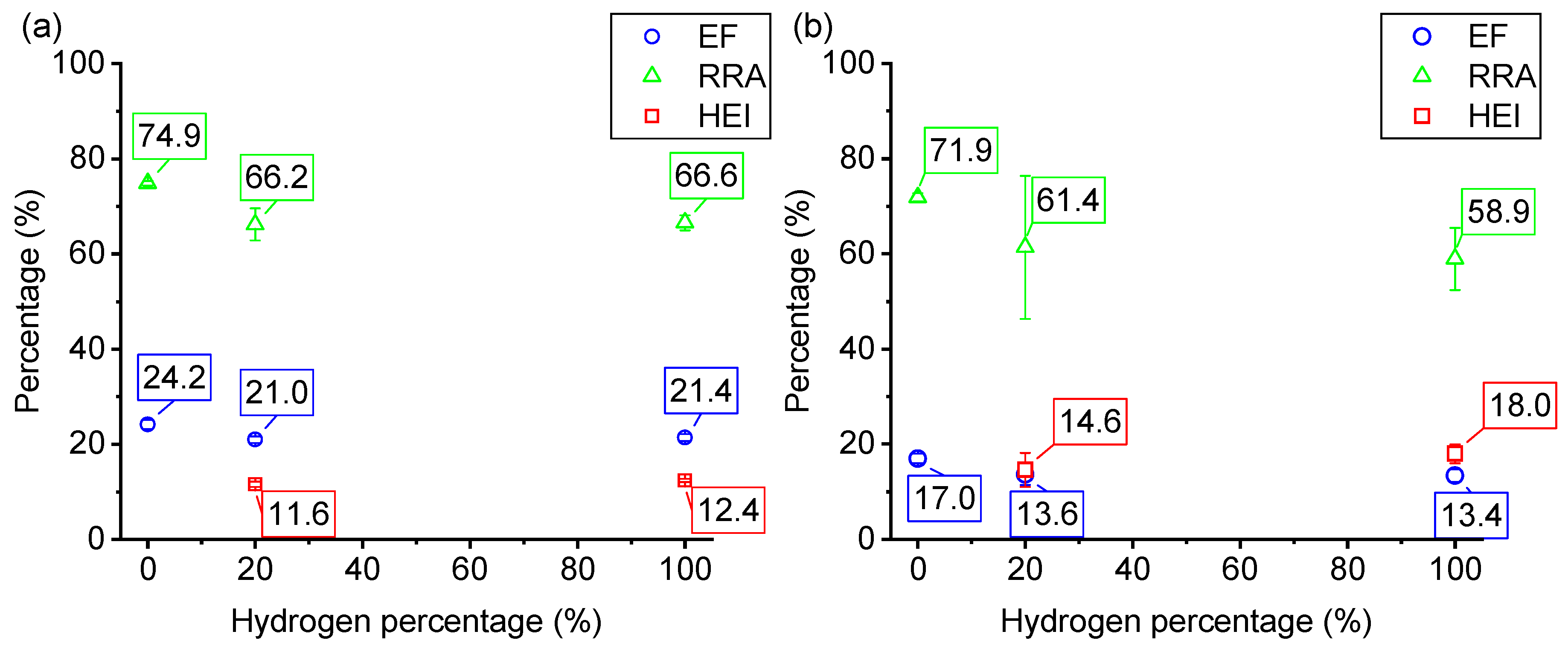
  • The yield and tensile strength of both the base and welded materials were not influenced significantly by exposure to hydrogen at the two tested concentrations. However, the ductility of both materials was notably reduced.
  • The hydrogen embrittlement index (HEI) used to represent ductility for both the base and welded materials showed limited change across both hydrogen concentrations (20% and 100%). This indicates that even at low hydrogen concentrations, there can be significant susceptibility to embrittlement.
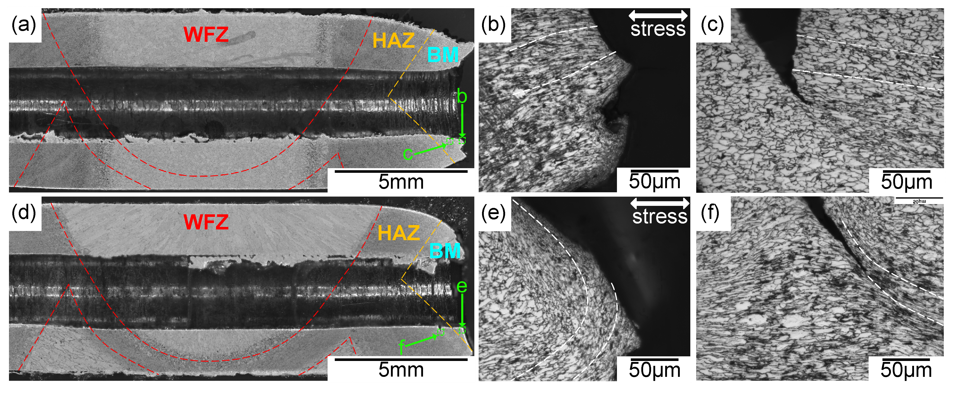
  • The region between the heat-affected and the surrounding base metal in the weld region exhibited the highest embrittlement with hydrogen. The reduced hardness near the heat-affected zone causes localized deformation, facilitating increased hydrogen diffusion and ultimately leading to hydrogen-assisted fractures compared to the base metal.
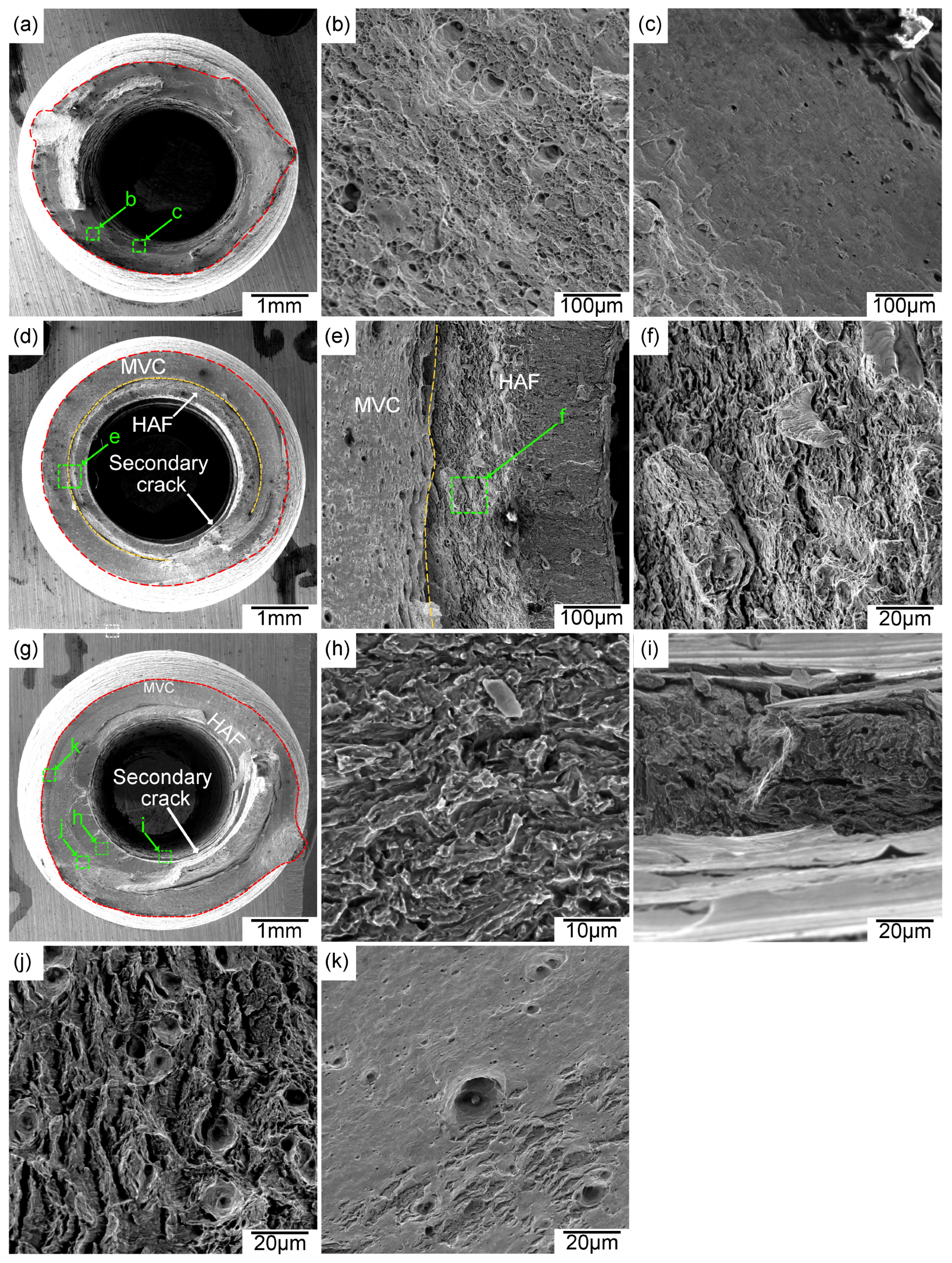
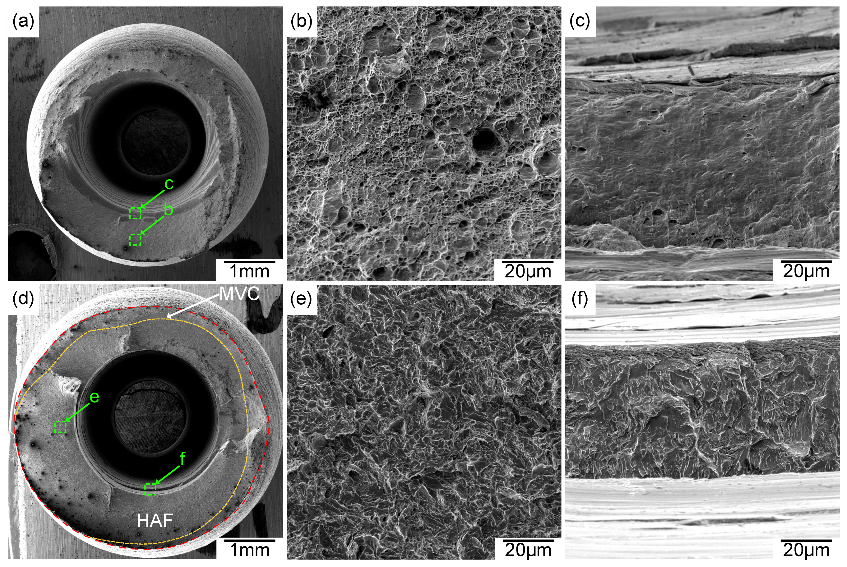
  • Fractography revealed that quasi-cleavage fractures are predominant in the hydrogen-assisted fracture region. Furthermore, highly localized plasticity was observed below the fracture surface. These findings explain the probable effect of the Hydrogen-Enhanced Localized Plasticity (HELP) mechanism.

Supplementary Materials

The following supporting information can be downloaded at: https://www.mdpi.com/article/10.3390/met14101132/s1, Video S1: Hollow specimen test knee point.

Author Contributions

Conceptualization, R.W., D.S., J.Q. and K.W.; methodology, R.W., M.C.H., D.S., J.Q., V.C. and M.H.; validation, R.W., D.S., J.Q., V.C. and K.W.; formal analysis, R.W., M.C.H., D.S. and K.W.; investigation, R.W., M.C.H. and D.S.; resources, R.W., M.C.H., D.S., J.Q., V.C., K.W. and M.H.; writing—original draft preparation, R.W. and M.C.H.; writing—review and editing, R.W., M.C.H., D.S., K.W. and M.H.; visualization, R.W. and M.H.; supervision, D.S. and J.Q.; project administration, D.S. and J.Q.; funding acquisition, D.S. and J.Q. All authors have read and agreed to the published version of the manuscript.

Funding

This work was supported by the Natural Sciences and Engineering Research Council of Canada under the Alliance Grant ALLRP 557088-20.

Data Availability Statement

The original contributions presented in the study are included in the article/Supplementary Materials, further inquiries can be directed to the corresponding author/s.

Acknowledgments

The authors are grateful for FortisBC’s guidance, financial support, expertise, and the pipeline material required to conduct this study. We thank Lukas Bichler for granting us access to the Spark OES and Keyence profilometer. Furthermore, we would like to thank David Enns for helping us to machine the hollow specimen.

Conflicts of Interest

Authors John Quinn, Vincent Chou, Kim Walker, and Matthew Hill are employed by the company FortisBC. The remaining authors declare that the research was conducted in the absence of any commercial or financial relationships that could be construed as a potential conflict of interest.

References

  1. Li, X.; Ma, X.; Zhang, J.; Akiyama, E.; Wang, Y.; Song, X. Review of Hydrogen Embrittlement in Metals: Hydrogen Diffusion, Hydrogen Characterization, Hydrogen Embrittlement Mechanism and Prevention. Acta Metall. Sin. 2020, 33, 759–773. [Google Scholar] [CrossRef]
  2. Zapffe, C.; Sims, C. Hydrogen embrittlement, internal stress and defects in steel. Trans. Aime 1941, 145, 225–271. [Google Scholar]
  3. Pfeil, L.B.; Carpenter, H.C.H. The effect of occluded hydrogen on the tensile strength of iron. Proc. R. Soc. Lond. Ser. Contain. Pap. Math. Phys. Character 1997, 112, 182–195. [Google Scholar] [CrossRef]
  4. Beachem, C.D. A new model for hydrogen-assisted cracking (hydrogen “embrittlement”). Metall. Trans. 1972, 3, 441–455. [Google Scholar] [CrossRef]
  5. Martin, M.; Connolly, M.; Delrio, F.; Slifka, A. Hydrogen embrittlement in ferritic steels. Appl. Phys. Rev. 2020, 7, 041301. [Google Scholar] [CrossRef] [PubMed]
  6. Lynch, S. Hydrogen embrittlement (HE) phenomena and mechanisms. In Stress Corrosion Cracking; Elsevier: Amsterdam, The Netherlands, 2011; pp. 90–130. [Google Scholar] [CrossRef]
  7. Lynch, S. Progress towards Understanding Mechanisms of Hydrogen Embrittlement and Stress Corrosion Cracking. In Proceedings of the CORROSION 2007, Nashville, TN, USA, 11–15 March 2007; p. NACE–07493. [Google Scholar]
  8. Dear, F.F.; Skinner, G.C.G. Mechanisms of hydrogen embrittlement in steels: Discussion. Philos. Trans. R. Soc. A Math. Phys. Eng. Sci. 2017, 375, 20170032. [Google Scholar] [CrossRef]
  9. Djukic, M.B.; Bakic, G.M.; Sijacki Zeravcic, V.; Sedmak, A.; Rajicic, B. The synergistic action and interplay of hydrogen embrittlement mechanisms in steels and iron: Localized plasticity and decohesion. Eng. Fract. Mech. 2019, 216, 106528. [Google Scholar] [CrossRef]
  10. Nibur, K.; Somerday, B. Fracture and fatigue test methods in hydrogen gas. In Gaseous Hydrogen Embrittlement of Materials in Energy Technologies; Elsevier: Amsterdam, The Netherlands, 2012; pp. 195–236. [Google Scholar] [CrossRef]
  11. ASTM G142-98(2016); Test Method for Determination of Susceptibility of Metals to Embrittlement in Hydrogen Containing Environments at High Pressure, High Temperature, or Both. ASTM International: West Conshohocken, PA, USA, 2016. [CrossRef]
  12. ISO 11114-4; Test Methods for Selecting Metallic Materials Resistant to Hydrogen Embrittlement. Transportable Gas Cylinders: Compatibility of Cylinder and Valve Materials with Gas Contents. ISO: Geneva, Switzerland, 2017.
  13. Michler, T.; Ebling, F.; Oesterlin, H.; Fischer, C.; Wackermann, K. Comparison of tensile properties of X60 pipeline steel tested in high pressure gaseous hydrogen using tubular and conventional specimen. Int. J. Hydrogen Energy 2022, 47, 34676–34688. [Google Scholar] [CrossRef]
  14. Boot, T.; Riemslag, T.A.C.; Reinton, E.T.E.; Liu, P.; Walters, C.L.; Popovich, V. In-Situ Hollow Sample Setup Design for Mechanical Characterisation of Gaseous Hydrogen Embrittlement of Pipeline Steels and Welds. Metals 2021, 11, 1242. [Google Scholar] [CrossRef]
  15. Chandler, W.T.; Walter, R.J. Testing to determine the effect of high-pressure hydrogen environments on the mechanical properties of metals. In Hydrogen Embrittlement Testing; ASTM International: West Conshohocken, PA, USA, 1974. [Google Scholar]
  16. Rahimi, S.; Scionti, G.; Piperopoulos, E.; Proverbio, E. Coupled slow strain rate and acoustic emission tests for gaseous hydrogen embrittlement assessment of API X65 pipeline steel. Mater. Lett. 2024, 367, 136598. [Google Scholar] [CrossRef]
  17. Konert, F.; Wieder, F.; Nietzke, J.; Meinel, D.; Böllinghaus, T.; Sobol, O. Evaluation of the impact of gaseous hydrogen on pipeline steels utilizing hollow specimen technique and μCT. Int. J. Hydrogen Energy 2024, 59, 874–879. [Google Scholar] [CrossRef]
  18. Konert, F.; Campari, A.; Nietzke, J.; Sobol, O.; Paltrinieri, N.; Alvaro, A. Evaluation of the tensile properties of X65 pipeline steel in compressed gaseous hydrogen using hollow specimens. Procedia Struct. Integr. 2024, 54, 204–211. [Google Scholar] [CrossRef]
  19. Michler, T.; Freitas, T.; Oesterlin, H.; Fischer, C.; Wackermann, K.; Ebling, F. Tensile testing in high pressure gaseous hydrogen using conventional and tubular specimens: Austenitic stainless steels. Int. J. Hydrogen Energy 2023, 48, 25609–25618. [Google Scholar] [CrossRef]
  20. Ogata, T.; Ono, Y. Influence of Roughness of Inner Surface of Simple Mechanical Testing Method to Evaluate Influence of High Pressure Hydrogen Gas. In Proceedings of the Volume 6B: Materials and Fabrication, San Antonio, TX, USA, 14–19 July 2019; p. V06BT06A032. [Google Scholar] [CrossRef]
  21. Ogata, T. Simple Mechanical Testing Method to Evaluate Influence of High Pressure Hydrogen Gas. In Proceedings of the Volume 6B: Materials and Fabrication, Prague, Czech Republic, 15–20 July 2018; p. V06BT06A028. [Google Scholar] [CrossRef]
  22. Ogata, T. Hydrogen Environment Embrittlement on Austenitic Stainless Steels from Room Temperature to Low Temperatures. IOP Conf. Ser. Mater. Sci. Eng. 2015, 102, 012005. [Google Scholar] [CrossRef]
  23. Ogata, T. Influence of high pressure hydrogen environment on tensile and fatigue properties of stainless steels at low temperatures. AIP Conf. Proc. 2012, 1435, 39–46. [Google Scholar] [CrossRef]
  24. Ogata, T.; Balachandran, U.B. Hydrogen environment embrittlement evaluation in fatigue properties of stainless steel SUS304L at cryogenic temperatures. AIP Conf. Proc. 2010, 1219, 25–32. [Google Scholar] [CrossRef]
  25. Ogata, T. Evaluation of Hydrogen Embrittlement by Internal High-Pressure Hydrogen Environment in Specimen. J. Jpn. Inst. Met. 2008, 72, 125–131. [Google Scholar] [CrossRef]
  26. Ronevich, J.A.; Somerday, B.P.; San Marchi, C.W. Effects of microstructure banding on hydrogen assisted fatigue crack growth in X65 pipeline steels. Int. J. Fatigue 2016, 82, 497–504. [Google Scholar] [CrossRef]
  27. ASTM E92-23; Test Methods for Vickers Hardness and Knoop Hardness of Metallic Materials. ASTM: West Conshohocken, PA, USA, 2024. [CrossRef]
  28. Meng, B.; Gu, C.; Zhang, L.; Zhou, C.; Li, X.; Zhao, Y.; Zheng, J.; Chen, X.; Han, Y. Hydrogen effects on X80 pipeline steel in high-pressure natural gas/hydrogen mixtures. Int. J. Hydrogen Energy 2017, 42, 7404–7412. [Google Scholar] [CrossRef]
  29. Nguyen, T.T.; Park, J.; Kim, W.S.; Nahm, S.H.; Beak, U.B. Effect of low partial hydrogen in a mixture with methane on the mechanical properties of X70 pipeline steel. Int. J. Hydrogen Energy 2020, 45, 2368–2381. [Google Scholar] [CrossRef]
  30. Nguyen, T.T.; Bae, K.O.; Jaeyeong, P.; Nahm, S.H.; Baek, U.B. Damage associated with interactions between microstructural characteristics and hydrogen/methane gas mixtures of pipeline steels. Int. J. Hydrogen Energy 2022, 47, 31499–31520. [Google Scholar] [CrossRef]
  31. Campari, A.; Konert, F.; Sobol, O.; Alvaro, A. A comparison of vintage and modern X65 pipeline steel using hollow specimen technique for in-situ hydrogen testing. Eng. Fail. Anal. 2024, 163, 108530. [Google Scholar] [CrossRef]
  32. González-Velázquez, J.L. Fractography and Failure Analysis; Structural Integrity; Springer International Publishing: Cham, Switzerland, 2018; Volume 3. [Google Scholar] [CrossRef]
Figure 1. Optical micrographs of the X60 base metal tested.
Metals 14 01132 g001
Figure 2. (a) Macroscopic image of the X60 weld, indicating weld fusion zone (WFZ), heat-affected zone (HAZ) and base metal (BM). (b) Microstructure of the WFZ. (c) Microstructure of the HAZ. (d) The measured Vickers hardness values of the welded region.
Metals 14 01132 g002
Figure 3. The approximate location of the extraction of tensile specimens. (a) Welded material. (b) Base material. (c) Hollow specimen dimensions (in mm) used for the study.
Metals 14 01132 g003
Figure 4. The measured roughness profile of the internal hole of the specimen. The black outline represents the cross-section of the hollow specimen.
Metals 14 01132 g004
Figure 5. Schematic diagram of the hollow specimen setup.
Metals 14 01132 g005
Figure 6. Selected stress vs. displacement curves for the base (a) and welded material (b). The arrow indicates the “knee point”.
Metals 14 01132 g006
Figure 7. Variation in the Elongation at Fracture (EF), Relative Reduction in Area (RRA) and hydrogen embrittlement index (HEI) for (a) base material and (b) welded material.
Metals 14 01132 g007
Figure 8. SEM images displaying the fracture surface of the base specimens. (a) Specimen exposed to methane. (b) Equiaxed dimples. (c,k) Parabolic dimples. (d) The fracture surface of the specimen exposed to 20% hydrogen. (e) HAF and MVC boundary. (f,j) QC and MVC in the transition zone. (g) The fracture surface of the specimen exposed to 100% hydrogen. (h,i) QC fracture.
Metals 14 01132 g008
Figure 9. SEM images displaying the fracture surface of the welded specimens. (a) Specimen exposed to methane. (b) Equiaxed dimples. (c) Parabolic dimples. (d) The fracture surface of the specimen exposed to 100% hydrogen. (e,f) QC fracture.
Metals 14 01132 g009
Figure 10. Optical micrographs of perpendicular cross-section surface to the fracture surface. (a,d) Weld specimen exposed to methane and hydrogen. The overlay indicates the WFZ, HAZ and BM. (b,e) Closeup of the fracture surfaces exposed to methane and hydrogen, respectively. (c,f) Closeup of the secondary crack exposed to hydrogen and methane, respectively. The white dotted lines in (b,c,e,f) represent the general grain flow.
Metals 14 01132 g010
Table 1. Chemical composition (wt.%) of the materials.
MaterialCMnSiNbCrCu
Base0.0871.4760.2190.0210.0180.011
Weld0.1071.3260.2910.0140.0170.012
Table 2. Mechanical properties of the base metal and the welded material.
MaterialDirectionYield StrengthTensile Strength
BaseLongitudinal477.5 ± 62.5 MPa560.0 ± 40.0 MPa
WeldCircumferentialNot present520.0 MPa
Disclaimer/Publisher’s Note: The statements, opinions and data contained in all publications are solely those of the individual author(s) and contributor(s) and not of MDPI and/or the editor(s). MDPI and/or the editor(s) disclaim responsibility for any injury to people or property resulting from any ideas, methods, instructions or products referred to in the content.

