Abstract
The powder spreading process is a fundamental element within the laser powder bed fusion (PBF-LP) framework given its pivotal role in configuring the powder bed. This configuration significantly influences subsequent processing steps and ultimately determines the quality of the final manufactured part. This research paper presents a comprehensive analysis of the impacts of varying spreading speeds, which are enabled by different roller configurations, on powder distribution in PBF-LP. By utilizing extensive Discrete Element Method (DEM) modelling, we systematically examine how spreading speed affects vital parameters within the spreading process, including packing density, mass fraction, and actual layer thickness. Our exploration of various roller configurations has revealed that increasing spreading speed generally decreases packing density and layer thickness for non-rotating, counter-rotating, and forward-rotating rollers with low clockwise rotational speeds (sub-rolling) due to powder dragging. However, a forward-rotating roller with a high clockwise rotational speed (super-rolling) balances momentum transfer, enhancing packing density and layer thickness while increasing surface roughness. This configuration significantly improves the uniformity and density of the powder bed, providing a technique to accelerate the spreading process while maintaining and not reducing packing density. Furthermore, this configuration offers crucial insights into optimizing additive manufacturing processes by considering the complex relationships between spreading speed, roller configuration, and powder spreading quality.
1. Introduction
Laser powder bed fusion (PBF-LP) has emerged as a leading additive manufacturing technique that can produce complex and high-precision components, and it has diverse applications ranging from aerospace to biomedical engineering. At the heart of PBF-LP lies the controlled deposition of successive layers of fine powder, which is followed by laser scanning to selectively fuse and solidify the material [1,2,3]. The initial spreading of the powder material significantly influences the efficiency and quality of this layer-by-layer deposition process. In the domain of powder dispersion techniques in additive manufacturing, roller-spreading and blade-spreading are two separate approaches. Roller-spreading [4,5,6] involves using a roller mechanism to distribute powder, while blade-spreading [7,8] utilizes a blade to push and distribute powder material across the printing surface. Roller-spreading and blade-spreading techniques have significant differences in powder distribution efficiency. Roller-spreading typically achieves higher packing density due to the normal force exerted by the roller, which compacts the powder more effectively and promotes tighter particle packing through uniformly distributed force chains [5].
Reducing production time is of utmost importance in additive manufacturing, specifically concerning the duration of powder spreading [9,10]. By decreasing the duration of powder spreading, manufacturers can achieve accelerated production cycles, decreased lead times, and heightened productivity. This reduction in production time allows for swift responses to market demands, and it expedites product development and enables rapid delivery of customized or on-demand parts. Moreover, shorter production times yield cost savings and improved resource utilization. However, it is crucial to strike a delicate balance between reducing production time and upholding the integrity and quality of the final parts. Employing adequate control and optimization of the powder spreading process is imperative to maintain uniformity, minimize defects, and meet the required specifications. The effective management of powder spreading time unlocks substantial benefits in terms of speed, agility, and cost-effectiveness, thereby bolstering competitiveness across various industries. The increase in spreading speed during spreader operations has a positive correlation with expedited processes, thereby reducing the temporal outlay for spreading activities and enhancing the overall temporal efficiency within the production workflow.
The spreading speed of the spreader is a critical factor influencing the powder layer’s quality. This speed determines the powder distribution rate and uniformity on the building plate. A shear force is generated as the spreader moves across the powder bed at a certain spreading speed. This force causes powder particles to slide and deform against each other, promoting their redistribution and breaking up agglomerates [11]. An escalation in the speed at which the blade spreads can contribute to a reduction in the packing density [7,8,11,12,13,14,15,16,17,18]. This is due to the limited time for powder particles to settle and reorganize into a more tightly compacted configuration. In contrast, a slower spreading speed allows for increased settling and rearrangement of the powder particles, leading to a higher packing density. This behavior is observed consistently across various blade shapes [19,20,21,22,23]. Yao et al. [8] revealed an optimal operating parameter for spreading SS316L, which suggests that a spreading velocity of ≤0.1 m/s yields favorable results. However, the identified gap in the literature review underscores the necessity for additional experiments encompassing a more comprehensive range of traverse speeds to corroborate this finding. The spreading speed significantly influences the generation of shear force, which is a factor influenced by the counter-rotating roller’s motion that, in turn, leads to the breakup of powder agglomerates. However, the same spreading speed also results in a dragging effect on the powder, causing a decrease in the overall packing density [4,6,13,19,22,23,24]. Hence, the spreading speed governs roller-spreading’s essential shearing and dragging mechanisms. The circumferential speed of a counter-rotating roller pushes the powder forward in line with the spreading speed, ensuring consistent behavior at different rotational speeds. Conversely, in Seluga’s experimental work [25], it was observed that there was a marginal increase in powder bed density and an increase in traverse speed within the low-speed regime (below 12 mm/s). This observation suggests that increasing the speed does not impact packing density at extremely low spreading speeds. The rationale behind this behavior is attributed to the fact that at low spreading speeds, the powder needs time to propagate and settle within the building plate. This disparity underscores the intricate nature of the spreading process and implies that distinct mechanisms may come into play across varying speed regimes.
Numerous experimental and computational investigations have consistently demonstrated that augmenting the spreading speeds of the blade and counter-rotating roller processes leads to a reduction in layer thickness [12,16,20]. This phenomenon is attributed to the heightened dragging force that propels powders away from the substrate. The escalation in spreading speed induces a more turbulent trajectory of particles, resulting in heightened non-uniformity in packing density [8,15,21] and augmented surface roughness of the powder layer [4,17,22,23]. Particularly at heightened traverse speeds, particles deposited onto the powder bed retain substantial momentum, continuing to flow over a considerable distance. Consequently, this post-flow behavior results in an uneven surface and, in some instances, may give rise to the formation of a discontinuous layer.
Limited studies suggest that a forward-rotating roller improves powder bed density more than a counter-rotating roller or blade. The forward-rotating roller can grip and drag powder into the bed, thereby increasing the density [26,27]. However, this approach can also lead to uneven surfaces and inaccurate layer thickness as the powder bed may spring back after the roller passes due to the release of stored elastic energy [28]. The circumferential speed of a forward-rotating roller drags the powder backward, opposing the spreading speed. Therefore, the effect of increasing the spreading speed with a forward-rotating roller depends on the relationship between the spreading speed and the circumferential speed, which will be examined in our current study.
This research paper thoroughly and comprehensively analyzes the roller’s spreading speed effect on powder distribution in PBF-LP. The study aims to understand the complex relationships associated with the roller’s spreading speed under various rotation speed conditions by focusing on the forward-rotating configuration identified in the literature review. The investigation encompasses an in-depth exploration of the connections between the roller’s spreading speed and the characteristics of the powder layer. Through extensive Discrete Element Method (DEM) modelling, the study examines the influence of the spreading speed of the roller and its connection to both the layer thicknesses and packing densities of the powder layers. By addressing critical gaps identified in the literature and proposing practical solutions for enhancing process efficiency, this research contributes to advancing understanding and optimizing roller-based powder distribution in PBF-LP.
2. Methodology
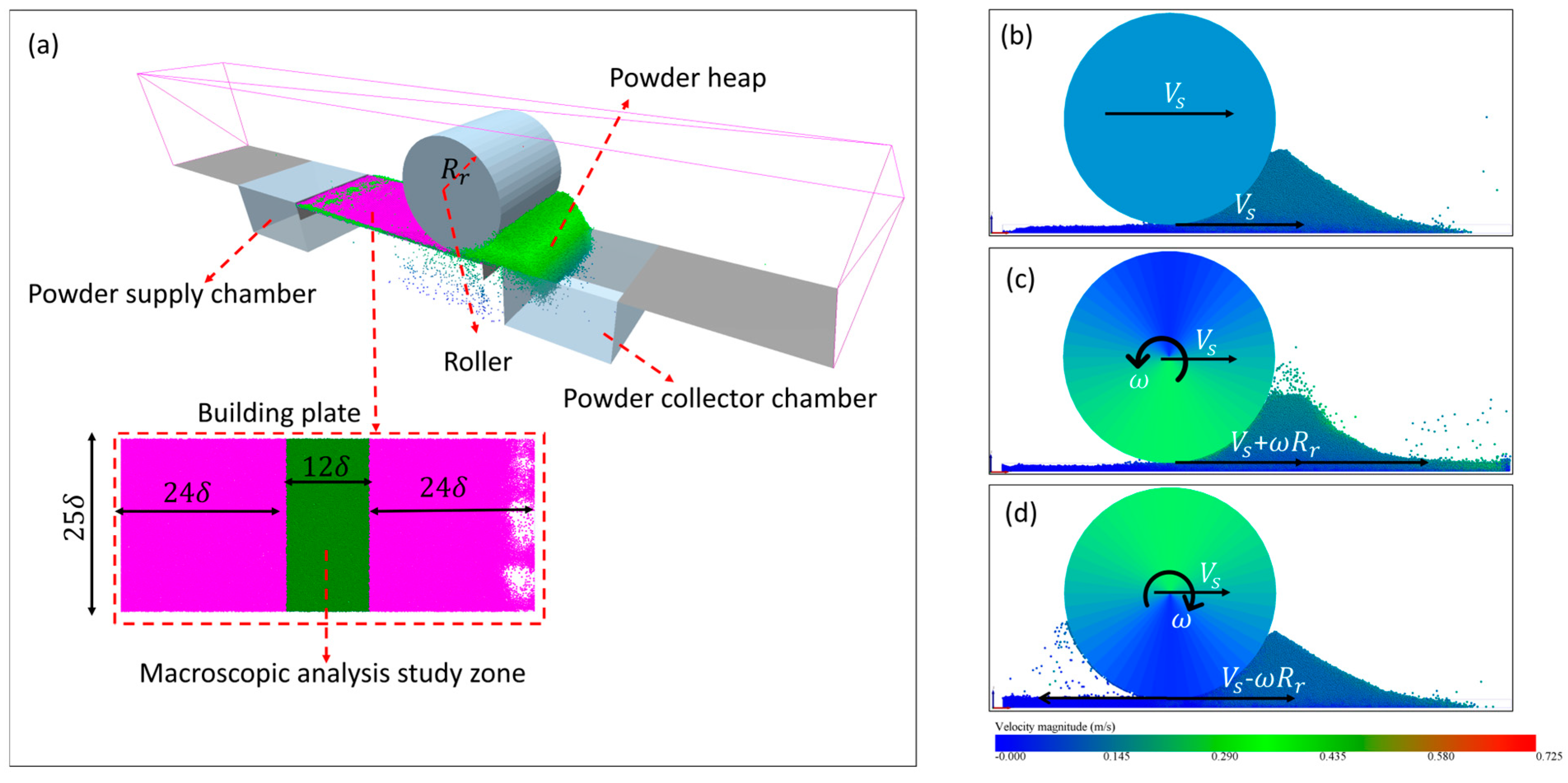
The PBF-LP process encompasses a powder-spreading system comprising three fundamental components: powder delivery, spreading and collection, as depicted in Figure 1d. A simplified computational domain focuses on the powder spreading process. The domain is shown in Figure 1a and includes the powder supply, collector chambers, the building plate, and the roller of radius 2.5 mm (). The dimensions of the domain and its components are normalized using the desired layer thickness (). Specifically, the domain length is 60 and the width is 25. Periodic conditions are applied in the y-direction. The roller is swept down the length of the domain with a uniform speed () while simultaneously rotating at a specified angular speed ().
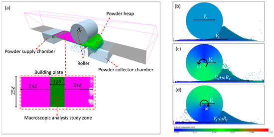
Figure 1.
(a) Schematic of DEM model of powder spreading process in PBF-LP using a rolling-spreading technique. (b) Non-rotating roller with a spreading speed of 0.15 m/s. (c) Counter-rotating roller with spreading speed of 0.15 m/s and counterclockwise rotational speed of 60 rad/s. (d) Forward-rotating roller with a spreading speed of 0.15 m/s and clockwise rotational speed of 60 rad/s. In (b–d), both the powder and roller are colored according to the velocity magnitude.
Roller-spreading cases can be classified into non-rotating, counter-rotating, and forward-rotating rollers based on the direction of the roller’s rotational speed relative to its translational spreading speed. In the non-rotating case, the roller moves at a constant spreading speed (Figure 1b, = 0.15 m/s) without any rotational motion, allowing the powder to be spread purely by translational movement. In the counter-rotating case, the roller rotates counterclockwise while advancing with spreading speed (Figure 1c, = 0.15 m/s and = 60 rad/s), introducing a circumferential speed velocity component in the same direction as the spreading at the roller bottom (i.e., surface velocity equals ). For the forward-rotating case, the roller rotates clockwise while advancing with spreading speed (Figure 1d, = 0.15 m/s and = 60 rad/s), introducing a circumferential speed velocity opposite to the direction of spreading at the roller bottom (i.e., surface velocity equals − ).
2.1. Mathematical Model
In bed particles, the translational motion and rotational motion of each particle [29,30] are governed by the following expressions:
where , , , and are the mass, velocity, angular velocity, and moment of inertia of particle respectively; and are the normal and tangential interaction forces on particle due to other particles , and and are the torques generated by tangential force and rolling friction. The kinematics of all particles are updated by the time integration of the previous equations [31].
Normal and tangential forces represent contributions of the contact forces between particles and the damping forces, which are added artificially to resolve the dissipation of kinetic energy. The normal and tangential forces have contact and damping force contributions:
The Hertz–Mindlin contact model [32] with Johnson–Kendall–Roberts (JKR) [33] cohesion formulates the contact forces between particles (the same used for particles and walls with different coefficients), accounting for the influences of Van der Waals forces within the contact zone:
where , , , and are the equivalent radius, mass, Young’s modulus, and shear modulus:
where , , , , and are the radius, mass, Young’s modulus, shear modulus, and Poisson’s ratio, respectively; e, , , and are the coefficient of restitution, the surface energy, and the sliding and rolling friction coefficients; and are the normal and tangential relative velocities between particles i and j when a collision occurs; and and are the normal and tangential overlaps between particles i and j when a collision occurs.
Friction torque is generated due to the moment of the tangential contact force. The rolling friction torque is created by applying a torque to the contact surfaces:
2.2. Numerical Model
The powder particle interactions are simulated by applying contact, friction, and cohesion forces as described in the previous mathematical model section. Altair EDEM software (2021.1) is used [34]. Selecting an appropriate time step is critical for achieving convergence and numerical stability. The time step used in these simulations is 1.62949 × 10⁻⁷ s, which is equivalent to 20% of the Rayleigh time, ensuring that the simulations accurately capture the dynamic processes and high-frequency phenomena while preventing instability and numerical errors. The mesh size is three times the radius of the smallest particle to ensure the accurate detection of particle contacts, resulting in 4,018,008 cells within the computational domain.
2.3. Performance Parameters of the Spreading Process
Packing density, layer thickness, and mass fraction are defined to characterize the powder bed layer and help examine how roller-spreading parameters impact the efficacy of powder packing. The packing density () is defined as the ratio of the volume that is actually occupied by particles () to the volume of the spatial configuration being encompassed (), with the latter being determined based on the desired layer thickness. Local packing densities are determined by dividing the building plate into N regions in the x-direction. The normalized variance of the packing density () over the bed gives a measure of the bed structure uniformity.
The local powder layer thickness () is the average of the maximum elevation of the particles resting on the building plate within each local (x-location) region. The global average or actual thickness () is simply the average of the local thickness and surface roughness () calculated using the centerline average method. The layer thickness and roughness can also be normalized with the desired layer thickness.
The mass fraction (MF) of the powder layer is the ratio of the mass of powder particles deposited on the building plate to the total mass of the powder layer that is supposed to fill the desired layer thickness. A global average mass fraction and its normalized variance are obtained from the local MF values in the x-direction. The packing density is equivalent to the mass fraction when the layer thickness is equal to or less than the desired thickness. However, if the layer thickness exceeds the desired value, the mass fraction becomes greater than the packing density. The packing density and layer thickness combination measures how much powder material is effectively placed on the surface during the spreading process. Moreover, the mass fraction indicates the spreader’s ability to distribute powder over the building plate.
In this study, we have taken a meticulous approach to address several simplifications and assumptions, especially regarding the use of an empty build plate for powder spreading. The choice of an empty build plate is not arbitrary; it is a careful decision that allows for better control of variables and isolates the effects of the roller on powder distribution. Simulating a loose powder layer introduces additional complex interactions beyond the primary focus of this investigation, including the dynamics of the roller and its impact on powder spread. By focusing on an empty build plate, we can concentrate on understanding the fundamental mechanisms of roller behavior without introducing the confounding variables that a loose powder layer may bring, thereby improving the clarity and precision of the findings.
2.4. Material Calibration and Model Verification
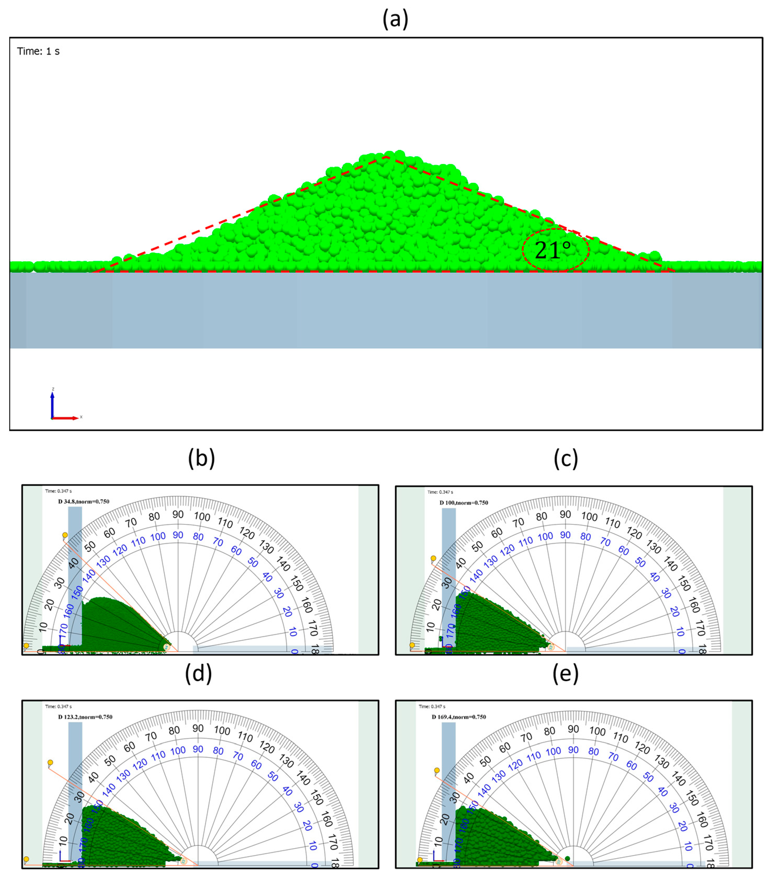
The calibration of the Discrete Element Method (DEM) poses a well-known challenge in the literature [35,36]. As a preliminary evaluation of the model’s performance, we compare the static angle of repose (AOR) formed by SS316 powder samples in both experimental and simulation settings. The simulation parameters of the material, including the surface energy and sliding/rolling friction coefficients, are adjusted to match the experimental and numerical predictions of the AOR. Table 1 [8,37] presents the simulation parameters range for SS316L, which are used in the process of material calibration. A reduced Young’s modulus is chosen to optimize the numerical stability of the model. This lower modulus helps achieve faster convergence during simulations by reducing the time step and ensuring efficient computation [18]. According to existing references, the AOR of SS316 is reported to be 21.3° [15,18]. By conducting an analysis of the effects of surface energy on the AOR, an optimal value of 0.001 is identified, leading to an AOR of 21.0°, as illustrated in Figure 2a.

Table 1.
DEM parameters of the SS 316L alloy.
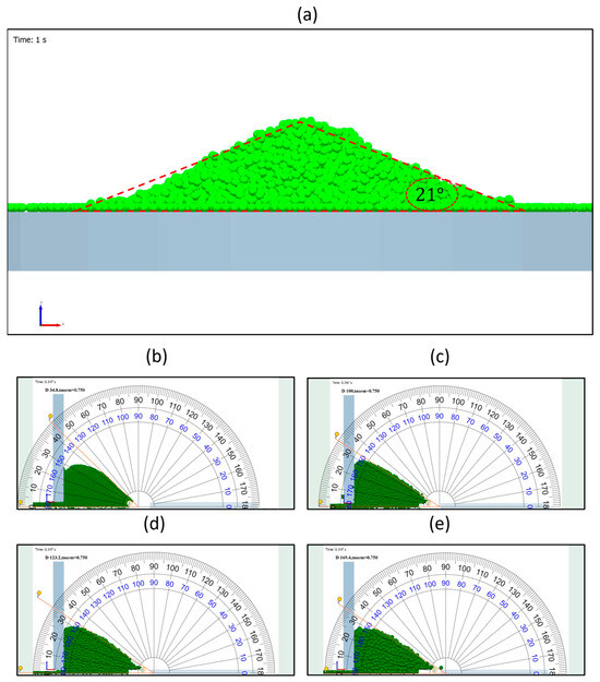
Figure 2.
Simulated angle of repose of SS316, assuming γ = 0.001 . (a) Static angle of repose; (b) Dynamic Repose Angle (DRA) for 34.8-µm-diameter powder. (c) DRA for 100 µm powder. (d) DRA for 123.2 µm powder. (e) DRA for 169.4 µm powder during blade spreading.
Further validation of the numerical model is performed by comparing the dynamic repose angle (DRA) of SS316 powder during powder spreading. Measurements by Yao et al. [8] are conducted using a rectangular blade moving with a spreading speed of 0.05 m/s for monomodal powder sizes of 34.8, 100, 123.2, and 166.4 µm. The current model’s roller is replaced with a similar blade to match the experimental setup, and the dynamic repose angles of powders of different sizes show good agreement with the experimental measurements, as illustrated in Figure 2b–e and Table 2. The error in the comparison remains below 9.6% in all cases.

Table 2.
Comparison of the calculated dynamic angle of repose with experimental and simulation values from Yao et al. [8].
2.5. Simulation Conditions
This study focuses on the influence of spreading speed on powder flow dynamics within the context of the roller spreading process. Spreading speed varies from 0.025 m/s to 0.15 m/s. The use of spreading speeds between 0.05 and 0.15 m/s aligns with many studies [8] that explore the fundamental mechanics of the powder-spreading process under controlled conditions. The interplay between the spreading speed and the roller rotation speed is considered by using four different rotation speeds: a non-rotating roller (), a counter-rotating roller ( = 60 rad/s), and two forward-rotating roller rotational speeds (10 and 60 rad/s). The two forward-rotating roller speeds are employed to simulate the effect of spreading speed when and when , respectively.
SS316 powder with a single particle size of 50 μm is used, mitigating the complicating influence of powder size distribution, and the ratio of powder size to the desired layer thickness is maintained at 0.25. After carefully considering various factors, we have chosen a selection of mono-sized particles with a particle diameter-to-layer thickness ratio of 0.25. This choice simplifies the model, ensures numerical stability, and allows us to isolate the effects of powder size distribution, focusing on the impact of spreading speed. This controlled environment enables us to study the influences of roller speed and spreading conditions without introducing the added complexities of polydisperse powders. The 0.25 ratio closely reflects realistic powder sizes [38], ensures sufficient powder packing, minimizes wall effects, and keeps our focus clear and unwavering.
3. Results and Discussion
As in the introduction, the effects of spreading speed have been previously investigated for non-rotating and counter-rotating rollers. Less attention has been paid to forward rolling, and little-to-no consideration has been given to the bed quality with the various regimes of forward rolling. There are cases that can be considered: pure rolling, sub-rolling, and super-rolling. Pure rolling occurs when the roller’s circumferential speed () matches the spreading speed (), sub-rolling occurs when the roller’s circumferential speed is less than the spreading speed, and super-rolling occurs when the roller’s circumferential speed is greater than the spreading speed. We start by presenting the results of the impacts of the spreading speed of non-rotating and counter-rotating rollers for our specific case of and then examine and compare the effects of forward rolling. The results section is categorized into two types of analyses: microscopic and macroscopic. Microscopic analysis investigates the variations in local packing density, mass fraction, layer thickness over the building plates, and cavity formation. Conversely, macroscopic analysis examines the variations in average packing density, mass fraction, layer thickness, and powder distribution uniformity concerning spreading speed.
3.1. Microscopic Analysis
3.1.1. Effect of Spreading Speed on the Non-Rotating Roller
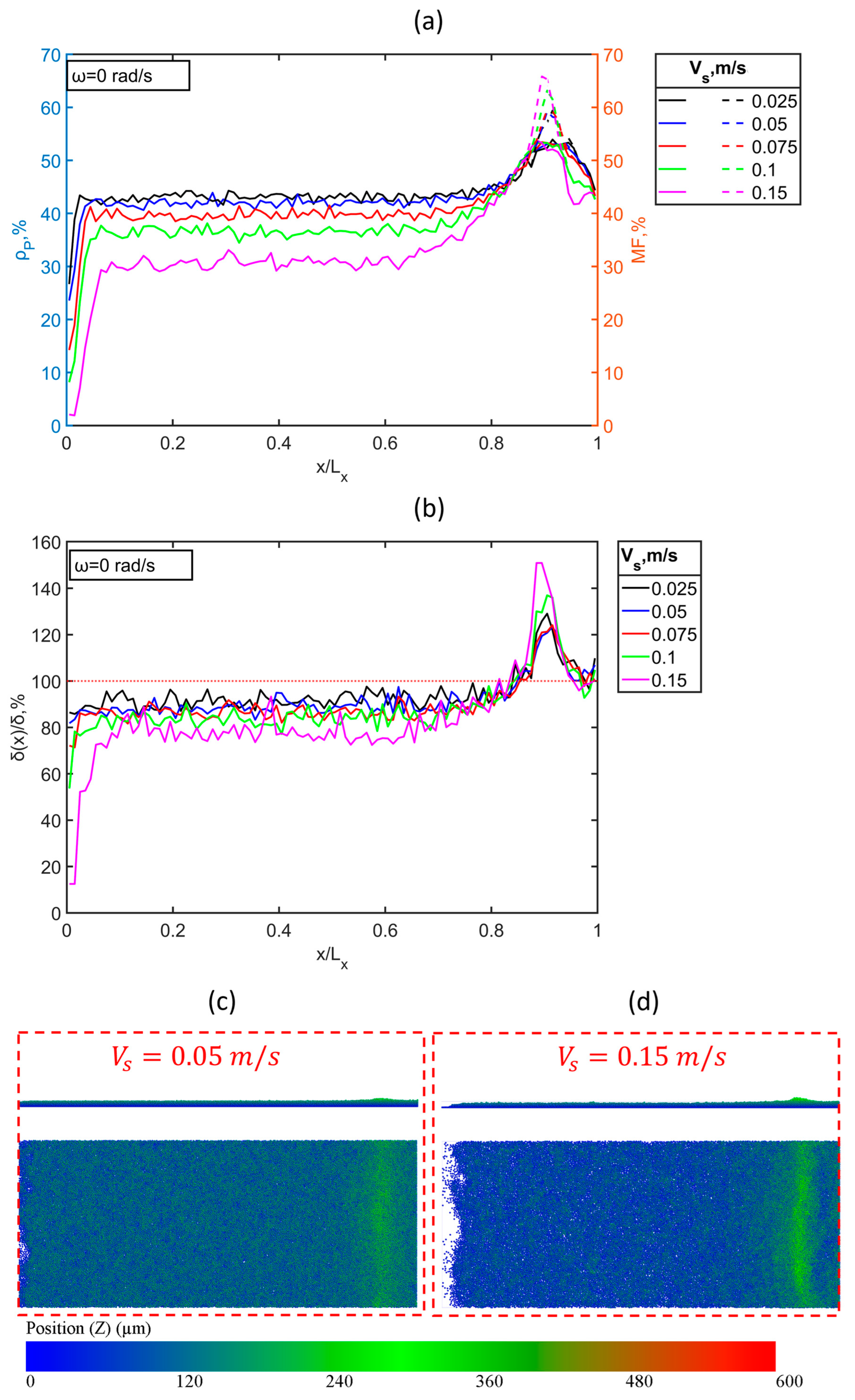
The non-rotating roller functions analogously to a blade and operates based on its spreading speed to distribute powder over the building plate. The packing density of the powder layer created by a non-rotating roller behaves similarly along the length of the building plate at different spreading speeds, which range from 0.025 to 0.15 m/s. Initially, the packing density increases to a certain level within the first 10% of the building plate length. Then, it fluctuates around this level, which is inversely proportional to the spreading speed, with more noticeable fluctuations at higher spreading speeds. Towards the final 20% of the building plate length, the packing density sharply rises to a maximum value before decreasing, as illustrated in Figure 3a. At a high spreading speed of 0.15 m/s, the roller displaces powder from the trailing edge (left side) to the leading edge (right side) of the building plate, resulting in the formation of a significant cavity on the trailing edge, as depicted in Figure 3c,d. The layer thickness distribution along the building plate mirrors the trend observed in packing density. The layer thickness fluctuates below the desired value throughout the majority of the building plate length, specifically to the last 20%. Notably, the peak in packing density corresponds to a peak in layer thickness, which frequently surpasses the desired layer thickness, as depicted in Figure 3b. This finding indicates a difference between this area’s packing density and mass fraction. Additionally, the fluctuations in layer thickness increase with the spreading speed.
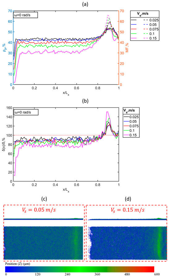
Figure 3.
Powder layer characteristics of the non-rotating roller versus the building plate length; (a) packing density (solid lines) and a mass fraction (dashed lines); (b) layer thickness; (c) top view and front view of the powder bed after spreading with the speed of 0.05 m/s; and (d) top view and front view of the powder bed after spreading with the speed of 0.15 m/s, colored by powder position in Z-direction (i.e., layer thickness).
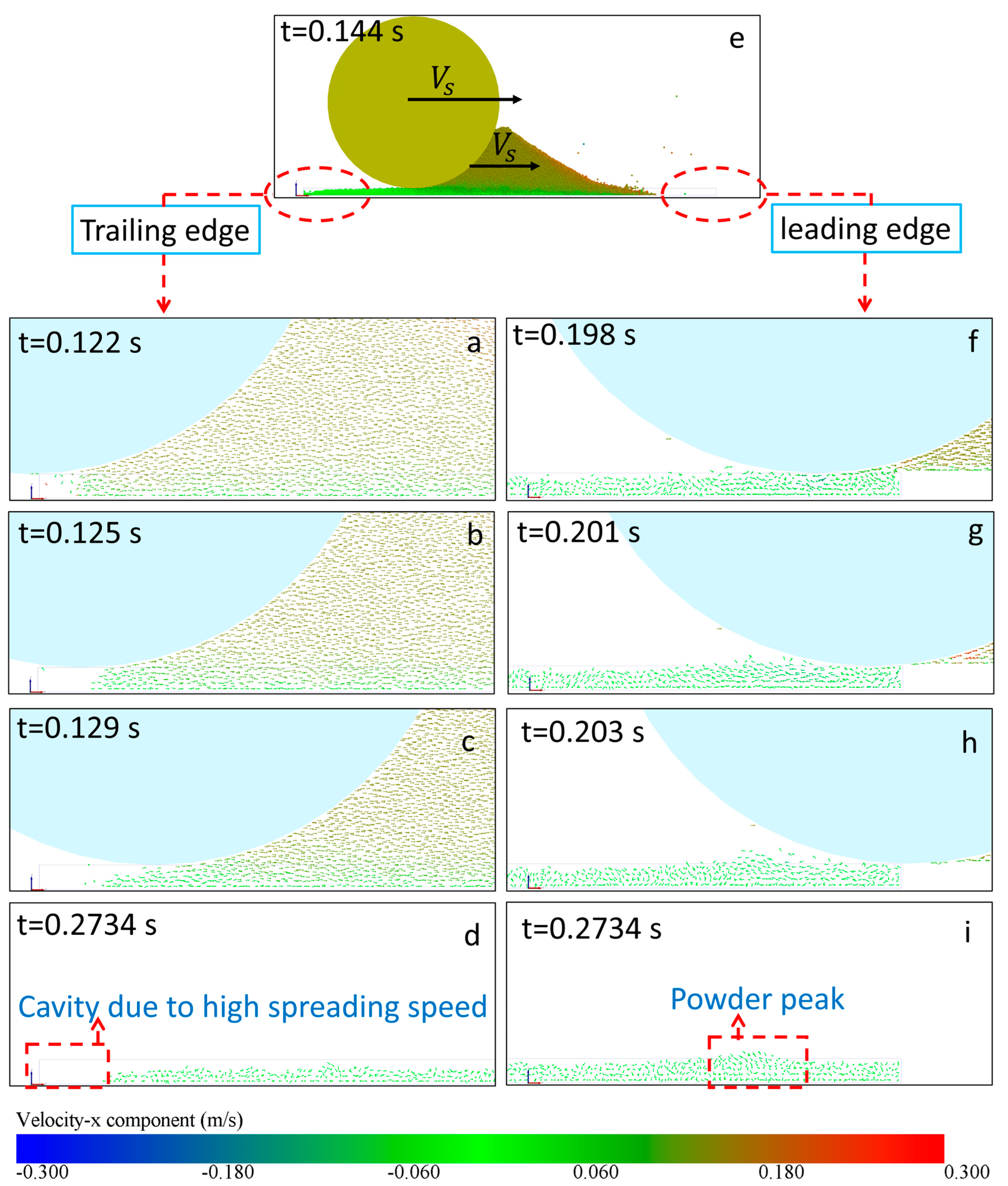
The behavior of powder spreading using a non-rotating roller can be explained by the dynamics of the roller and its interaction with the powder throughout the spreading process. At high spreading speeds, the roller pushes the powder away from the trailing edge due to the significant momentum transfer from the roller to the powder, creating a cavity. After the roller passes over the powder layer, the velocity of the powder decreases, and its direction changes to fill this cavity, as there is minimal resistance to flow. However, the amount of backflow is insufficient to fill the cavity, resulting in a large and continuous cavity at the trailing edge, as shown in Figure 4a–d. As the roller reaches the leading edge, the high-velocity powder collides with the solid boundary at the end of the building plate. This collision alters the powder’s direction and interaction with the developing powder layer. The result is a powder buildup just before the leading edge and a significant reduction in packing density before the solid boundary (i.e., rebound zone), as illustrated in Figure 4f–i.
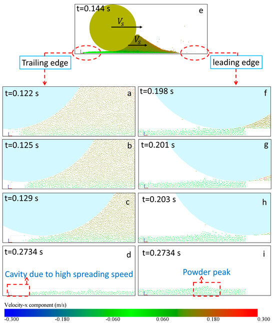
Figure 4.
(a–d,f–i) Velocity vector fields illustrating powder distribution for a non-rotating roller moving at 0.15 m/s during spreading. Subfigures (a–d) show the development of powder dynamics on the trailing edge (left side) of the building plate over time, while subfigures (f–i) depict the development on the leading edge (right side) over the same time intervals. Subfigure (e) shows the powder heap during the spreading process, with velocity vectors colored by the x-component of velocity, highlighting the flow and heap formation.
3.1.2. Effect of the Spreading Speed on Counter-Rotating Roller
The counter-rotating roller, which operates at an angular speed of 60 rad/s, undergoes variations in spreading speed from 0.025 to 0.15 m/s. The trend of packing density along the building plate for the counter-rotating roller is similar to that of the non-rotating roller. At lower spreading speeds, the packing density remains relatively stable along the length of the building plate with only minor fluctuations. However, as the spreading speed increases, significant variations occur, particularly in the last 20% of the building plate. In this region, the packing density sharply rises to peak values before abruptly decreasing, as shown in Figure 5a. Similarly, the layer thickness shows more intense fluctuations at higher spreading speeds, especially in the final 20% of the plate. This thickness remains below the desired value for most of the build plate length, as illustrated in Figure 5b. These fluctuations correspond with the peaks in packing density observed in Figure 5a, where the layer thickness exceeds the desired value, indicating that the mass fraction is greater than the packing density at this location. At a spreading speed of 0.05 m/s, the powder layer appears uniform and compact with minimal disturbances. In contrast, at a spreading speed of 0.15 m/s, the powder layer exhibits significant non-uniformity, with more pronounced small voids and lower powder compaction, which is consistent with the fluctuations observed in the graphs, as presented in Figure 5a,d. Consequently, small vacancies (voids) form within the powder layer produced by the counter-rotating roller as the spreading velocity increases (see the difference between this figure and Figure 5c,d). This finding from our simulations aligns with the results obtained by Chen et al. from their experimental imaging [4].
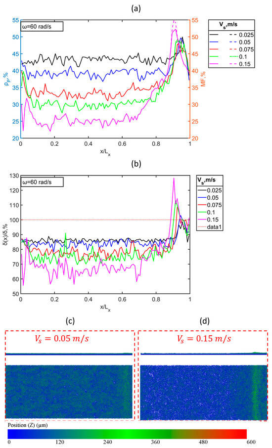
Figure 5.
Powder layer characteristics of a counter-rotating roller rotating at 60 rad/s versus building plate length. (a) Packing density (solid lines) and mass fraction (dashed lines), (b) layer thickness, and (c) top view and front view of the powder bed after spreading with the speed of 0.05 m/s. (d) Top view and front view of the powder bed after spreading with the speed of 0.15 m/s, colored by powder position in Z-direction (i.e., layer thickness).
The operation of a counter-rotating roller can be explained as the interplay between the linear spreading velocity in the x-direction and the circumferential velocity generated by the roller’s counterclockwise rotation. The circumferential velocity introduces an additional x-velocity component to the roller surface, enhancing the transfer of x-momentum to the powder layer, as shown in Figure 6e. As the roller initiates the powder spreading process on the building plate, it is anticipated that the powder will be displaced from the trailing edge, resulting in a cavity similar to that observed with a non-rotating roller. However, observations show a notable decrease in the powder layer after the roller has passed instead of a clearly defined cavity, as illustrated in Figure 6a–d. This reduction is attributed to the heightened momentum transfer from the roller to the powder. The counterclockwise rotation of the roller also introduces a y-direction momentum component, dispersing and lifting the powder upwards, which prevents the formation of a distinct cavity at the trailing edge and promotes a reduction in powder density within the layer. Analogous to the behavior of a non-rotating roller, as the counter-rotating roller approaches the leading edge, the high-velocity powder collides with the solid boundary at the end of the build plate. This collision alters the powder’s trajectory and interaction with the forming layer, leading to powder accumulation just before the leading edge and a significant decrease in packing density near the solid boundary, as shown in Figure 6f–i.
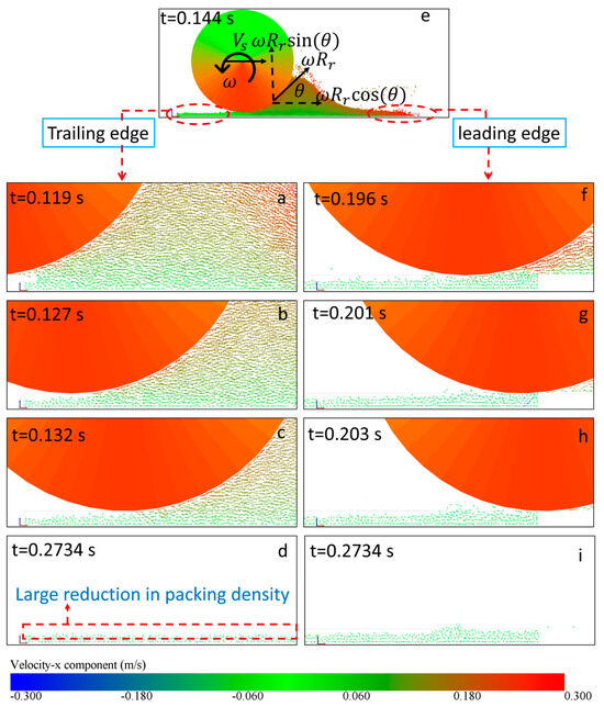
Figure 6.
(a–d,f–i) Velocity vector fields illustrating powder distribution for a counter-rotating roller moving at 0.15 m/s and rotating at 60 rad/s during spreading. Subfigures (a–d) show the development of powder dynamics on the trailing edge (left side) of the building plate over time, while subfigures (f–i) depict the development on the leading edge (right side) over the same time intervals. Subfigure (e) shows the powder heap during the spreading process with velocity vectors colored by the x-component of velocity, highlighting the flow and heap formation.
3.1.3. Effect of the Spreading Speed on Forward-Rotating Roller
The movement of a forward-rotating roller pertains to its horizontal displacement in the positive x-direction across a surface caused by its spreading speed. Concurrently, the roller’s clockwise rotation generates additional velocity at its surface. The x-component of this velocity, being in the negative x-direction, contributes to the roller’s surface speed by subtracting the spreading speed and the x-component of the tangential speed. This analysis allows us to divide the roller’s movement into two distinct categories: sub-rolling and super-rolling. Sub-rolling occurs when the spreading speed is greater than or equal to the circumferential speed, while super-rolling occurs when the spreading speed is less than or equal to the circumferential speed.
Sub-Rolling
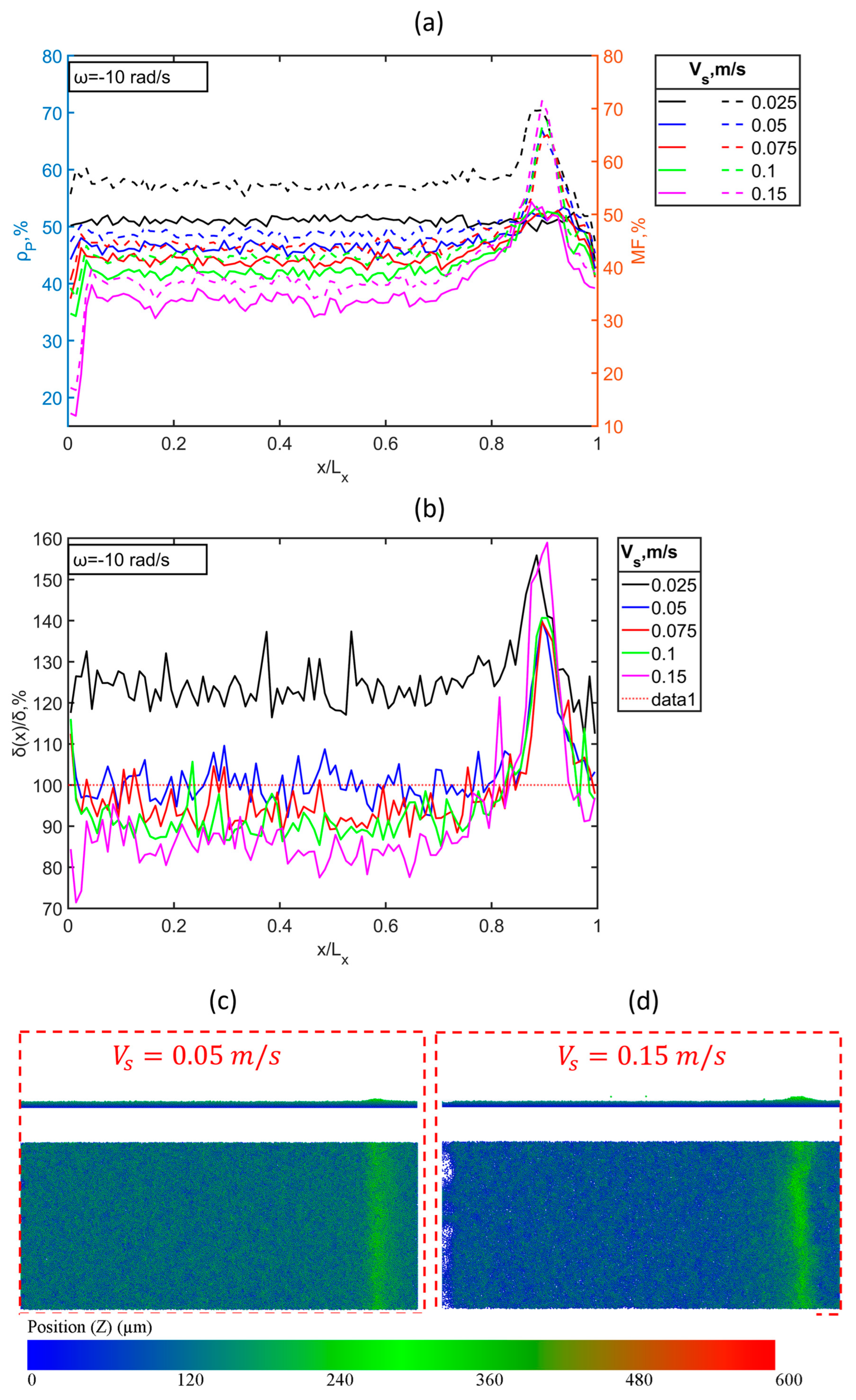
In this setup, a roller rotates forward at a speed ranging from 0.025 m/s to 0.15 m/s while rotating clockwise at 10 rad/s. In each simulation, the spreading speed is ensured to be greater than or equal to the circumferential speed. At a spreading speed of 0.025 m/s, the packing density remains stable along the entire length of the building plate, with only a slight reduction at the leading edge. As the spreading speed increases, the packing density at the trailing edge experiences an initial reduction, and it then increases to a specific value with fluctuations around it; it finally decreases again at the leading edge, as shown in Figure 7a. These fluctuations become more pronounced at higher spreading speeds. Notably, the packing density reductions at the trailing and leading edges intensify as the spreading speed increases. A small and discontinuous cavity formation in the powder at the trailing edge at 0.15 m/s supports this observation, as presented in Figure 7c,d. The mass fraction trends align with the packing density but are generally higher. As the spreading speed increases, the difference between the packing density and the mass fraction narrows. The layer thickness also fluctuates along the building plate, often exceeding the desired layer thickness at the leading edge, where the mass fraction is significantly higher than the packing density. The layer thickness exceeds the desired value at a spreading speed of 0.025 m/s, as illustrated in Figure 7b. Similar to non-rotating and counter-rotating rollers, the layer thickness and packing density decrease with increasing spreading speed.
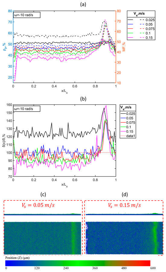
Figure 7.
Powder layer characteristics of the forward-rotating roller rotating at 10 rad/s (i.e., sub-rolling case) versus the building plate length. (a) Packing density (solid lines) and mass fraction (dashed lines), (b) layer thickness, and (c) top view and front view of the powder bed after spreading with the speed of 0.05 m/s. (d) Top view and front view of the powder bed after spreading with the speed of 0.15 m/s, colored by powder position in Z-direction (i.e., layer thickness).
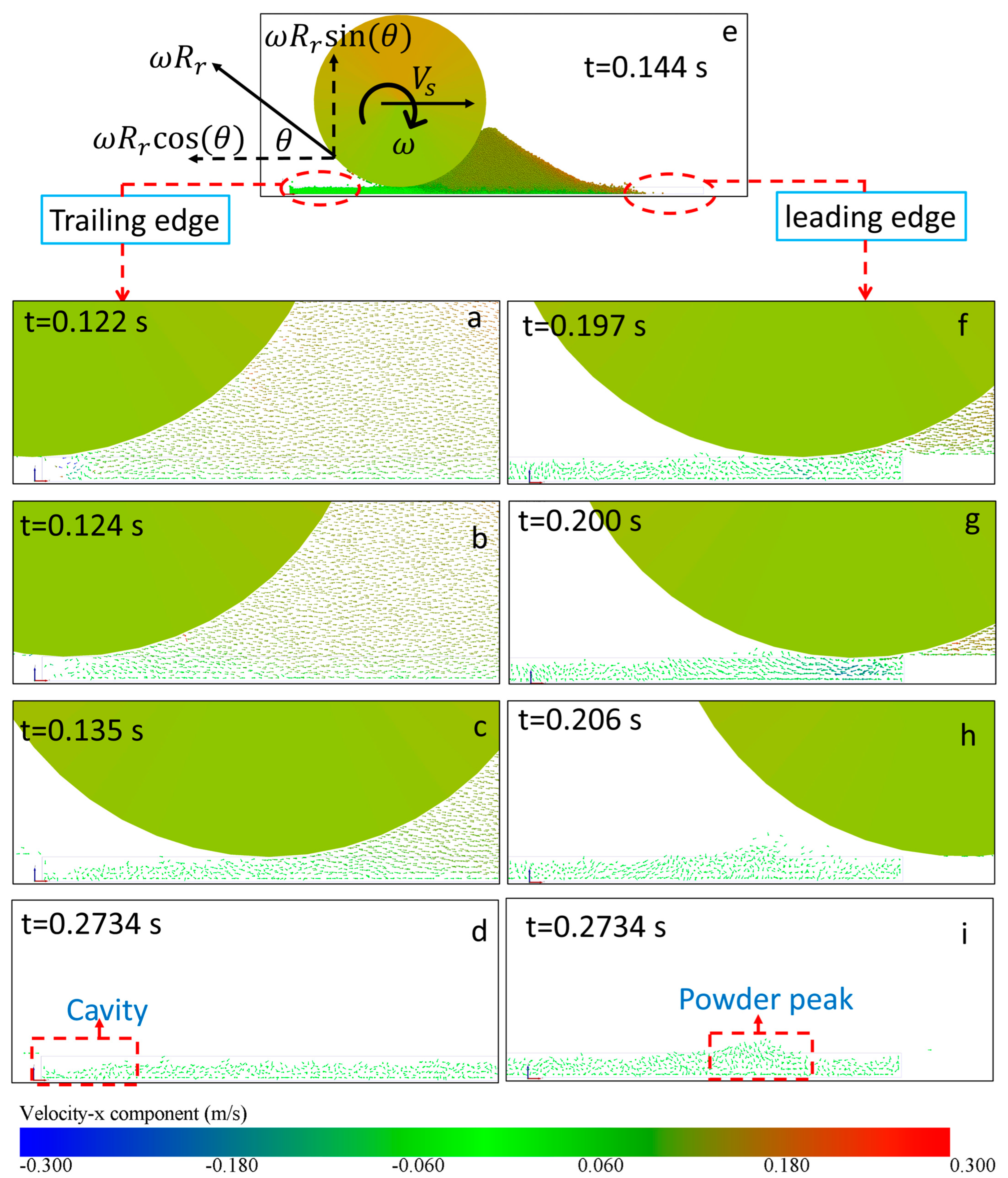
The roller generates significant force as it moves quickly across the powder, pushing it away from the edge behind it. This force, caused by the roller’s speed, is counteracted by the negative x-component of the circumferential speed. As a result, less powder is pulled along by the roller, leading to smaller discontinuous cavities at the trailing edge compared to the scenario in which the roller is not rotating (the cavity is large and continuous), as shown in Figure 8a–d. As the roller approaches the leading edge, the high-speed powder collides with the solid boundary at the end of the build plate. This collision redirects the powder and influences how it interacts with the developing powder layer. Additionally, the circumferential speed pulls powder from the heap in front of the roller, causing it to spread in opposite directions. Consequently, there is a buildup of powder just before the leading edge, resulting in a noticeable decrease in packing density near the leading edge, as illustrated in Figure 8f–i. At low spreading speeds, the circumferential speed causes the powder to disperse backward along the building plate, countering the motion of the roller. In some cases, such as at 0.025 and 0.05 m/s, more powder accumulates above the desired layer thickness, causing the mass fraction to exceed the packing density.
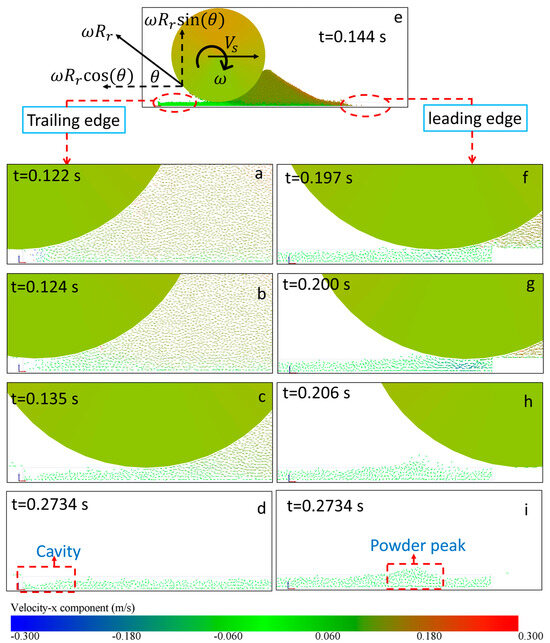
Figure 8.
(a–d,f–i) Velocity vector fields illustrating powder distribution for a forward-rotating roller moving at 0.15 m/s and rotating at 10 rad/s during spreading. Subfigures (a–d) show the development of powder dynamics on the trailing edge (left side) of the building plate over time, while subfigures (f–i) depict the development on the leading edge (right side) over the same time intervals. Subfigure (e) shows the powder heap during the spreading process, with velocity vectors colored by the x-component of velocity, highlighting the flow and heap formation.
Super-Rolling
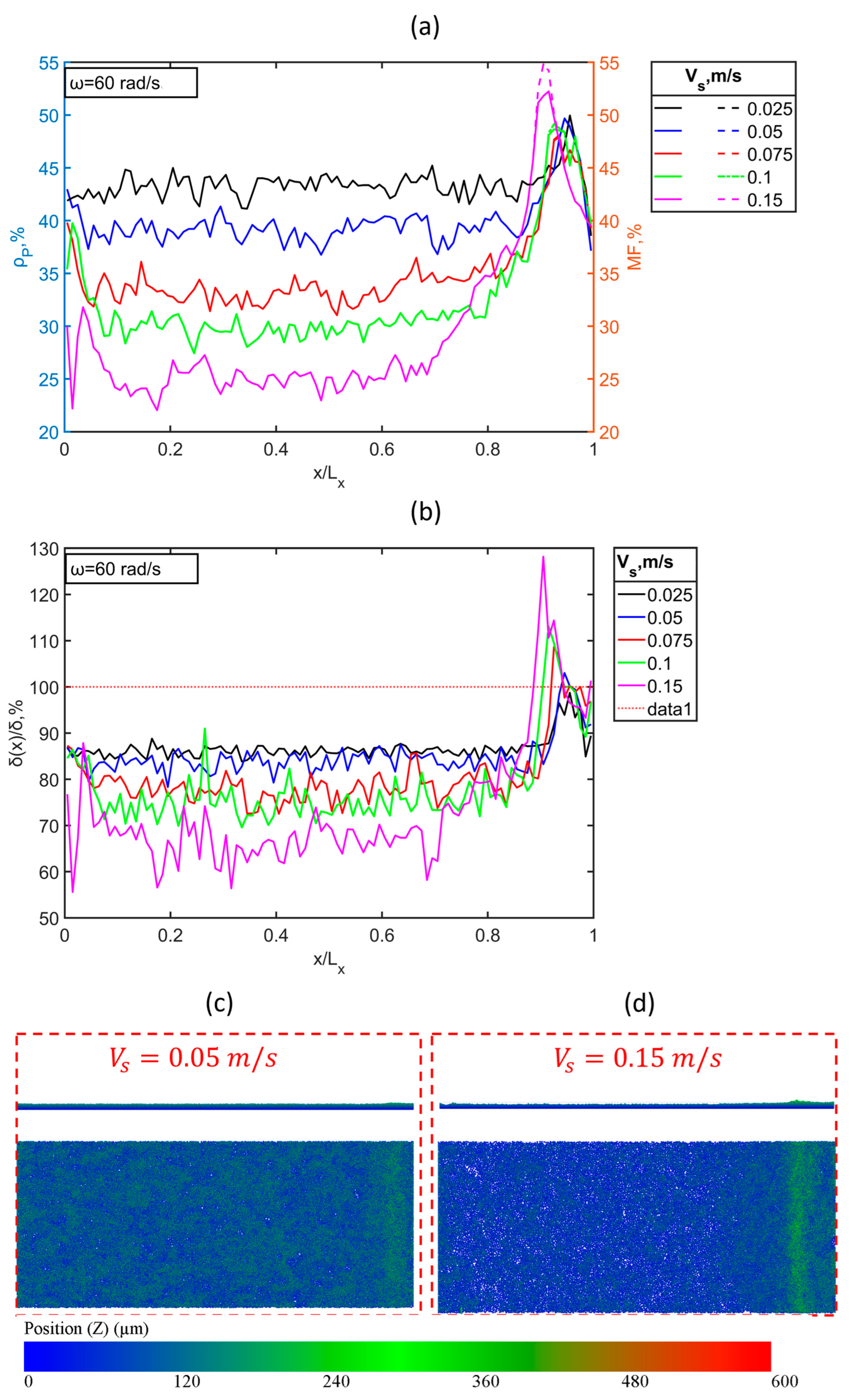
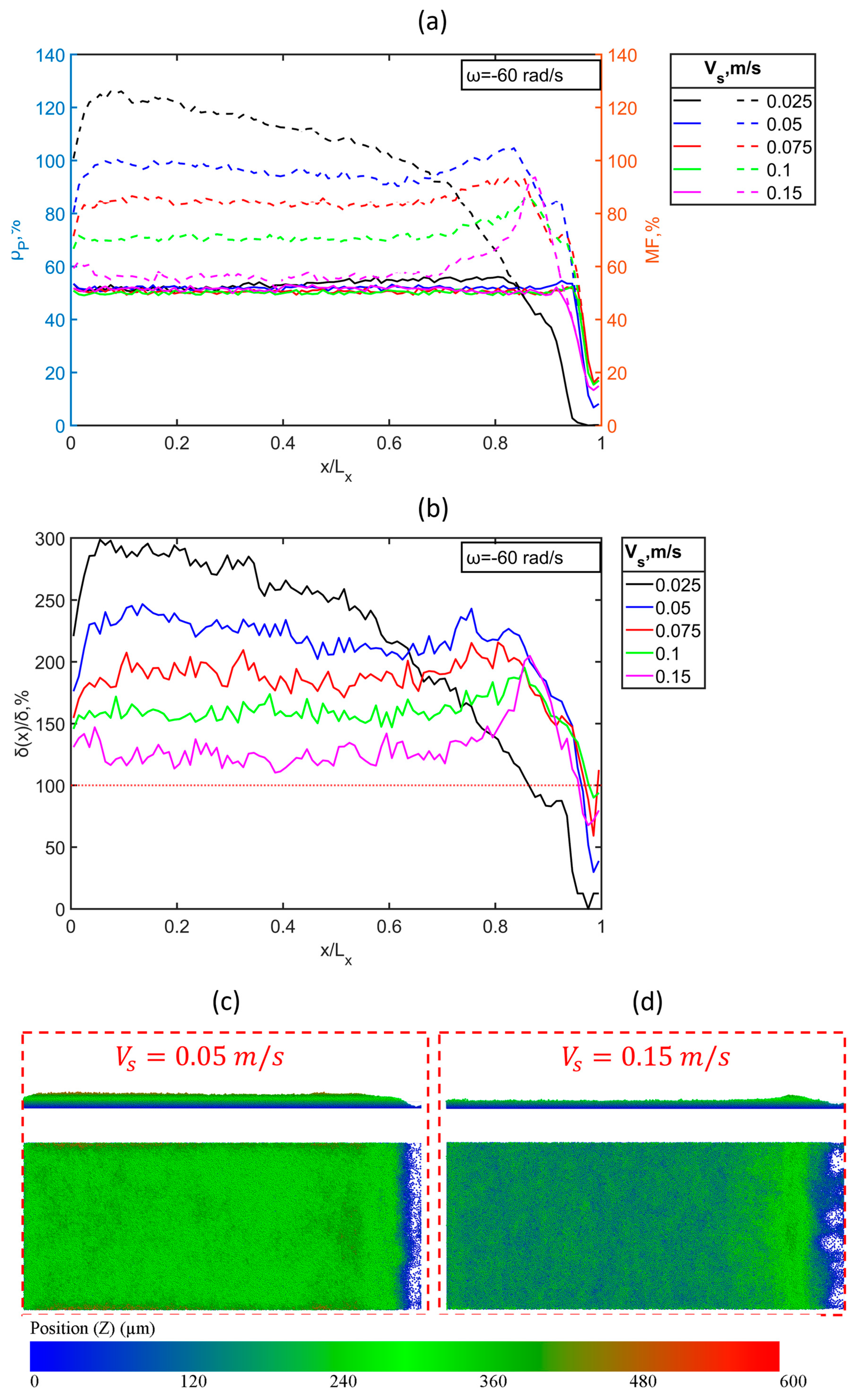
In this experimental setup, a forward-rotating roller operates at a spreading speed ranging from 0.025 m/s to 0.15 m/s while rotating clockwise at 60 rad/s. Throughout the simulations, it is ensured that the spreading speed is either smaller than or equal to the circumferential speed of the roller. The packing density remains relatively stable, fluctuating around a consistent average value at different spreading speeds. However, a significant reduction in packing density is observed at the leading edge, with the extent of this reduction being inversely proportional to the spreading speed. It is observed that a continuous cavity is formed at a leading edge at a low spreading velocity (i.e., and become small and discontinuous cavities at a high spreading speed (i.e., ), as presented in Figure 9c,d. At a spreading speed of 0.025 m/s, the mass fraction peaks at the trailing edge and gradually decreases, culminating in a substantial reduction at the leading edge, as shown in Figure 9a. As the spreading speed increases, the mass fraction tends to fluctuate around values higher than the packing density, which is followed by a marked reduction at the leading edge. The variation in layer thickness along the building plate length mirrors the trend observed in packing density. It consistently remains higher than the desired layer thickness, except at the leading edge, where it falls below the desired value, as presented in Figure 9b. Both the mass fraction and layer thickness decrease as the spreading speed increases.
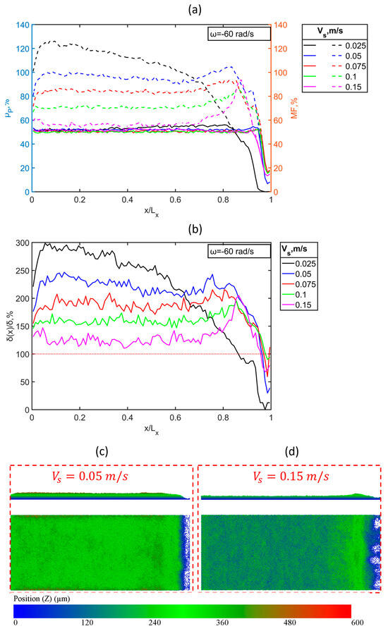
Figure 9.
Powder layer characteristics of a forward-rotating roller rotating at 60 rad/s (i.e., super-rolling case) versus the building plate length. (a) Packing density (solid lines) and mass fraction (dashed lines), (b) layer thickness, and (c) top view and front view of the powder bed after the spreading process with the speed of 0.05 m/s. (d) Top view and front view of the powder bed after spreading with the speed of 0.15 m/s, colored by powder position in Z-direction (i.e., layer thickness).
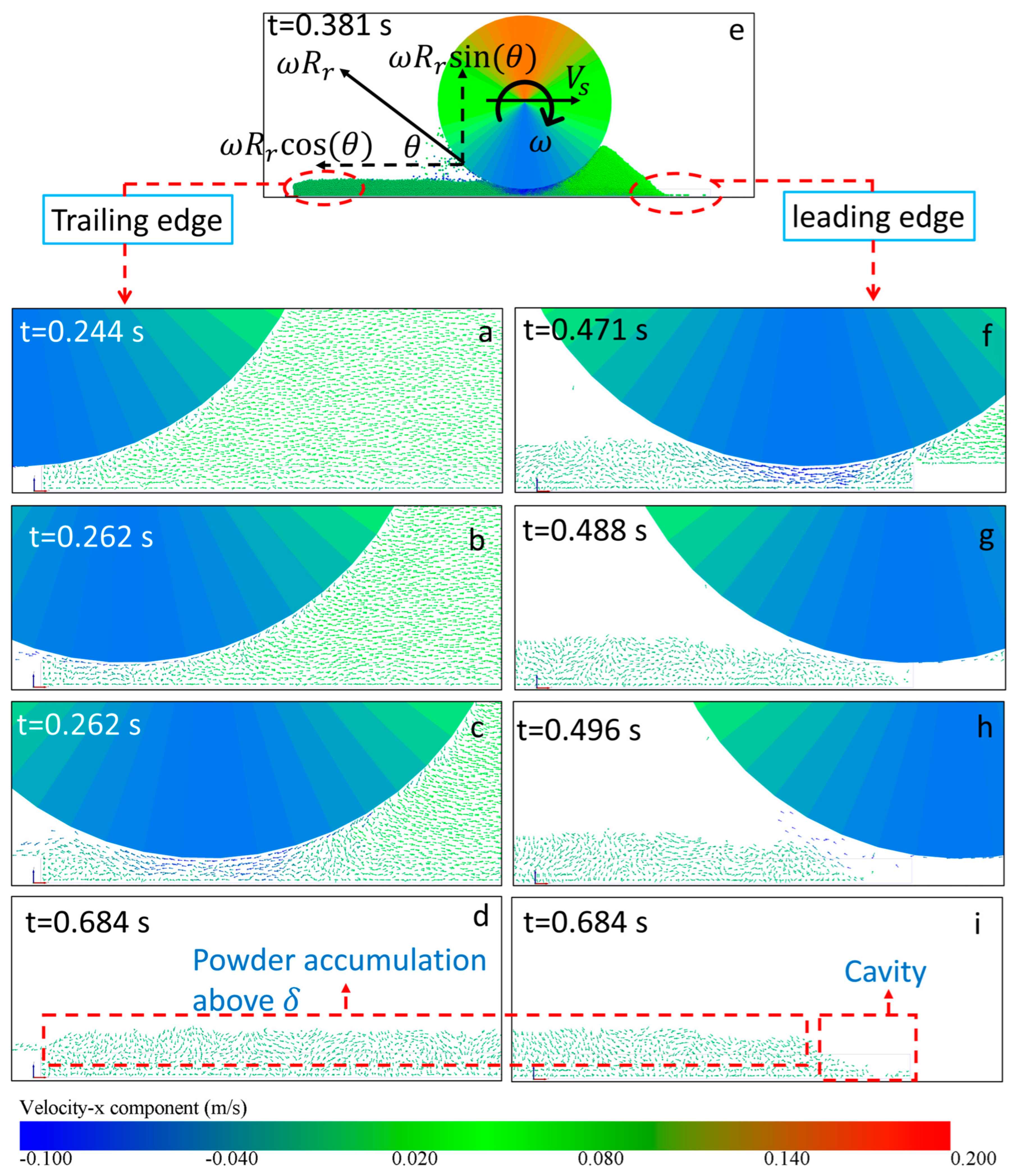
The main feature of a forward-rotating roller, particularly in the context of super-rolling, is its rapid clockwise rotation. This rotation produces a negative x-component and a positive y-component on the roller’s rear surface. The negative x-component exerts a force that pushes the powder in the opposite direction of the spreading motion. In contrast, the positive y-component disperses the powder (powder burst) across the building plate once the roller has passed. This process increases powder accumulation on the building plate, causing the layer thickness to exceed the desired level along the entire plate length, except at the leading edge, as illustrated in Figure 10a–d.
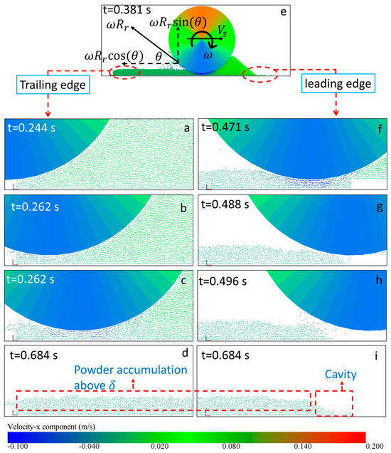
Figure 10.
(a–d,f–i) Velocity vector fields illustrating powder distribution for a forward-rotating roller moving at 0.05 m/s and rotating at 60 rad/s during spreading. Subfigures (a–d) show the development of powder dynamics on the trailing edge (left side) of the building plate over time, while subfigures (f–i) depict the development on the leading edge (right side) over the same time intervals. Subfigure (e) shows the powder heap during the spreading process, with velocity vectors colored by the x-component of velocity, highlighting the flow and heap formation.
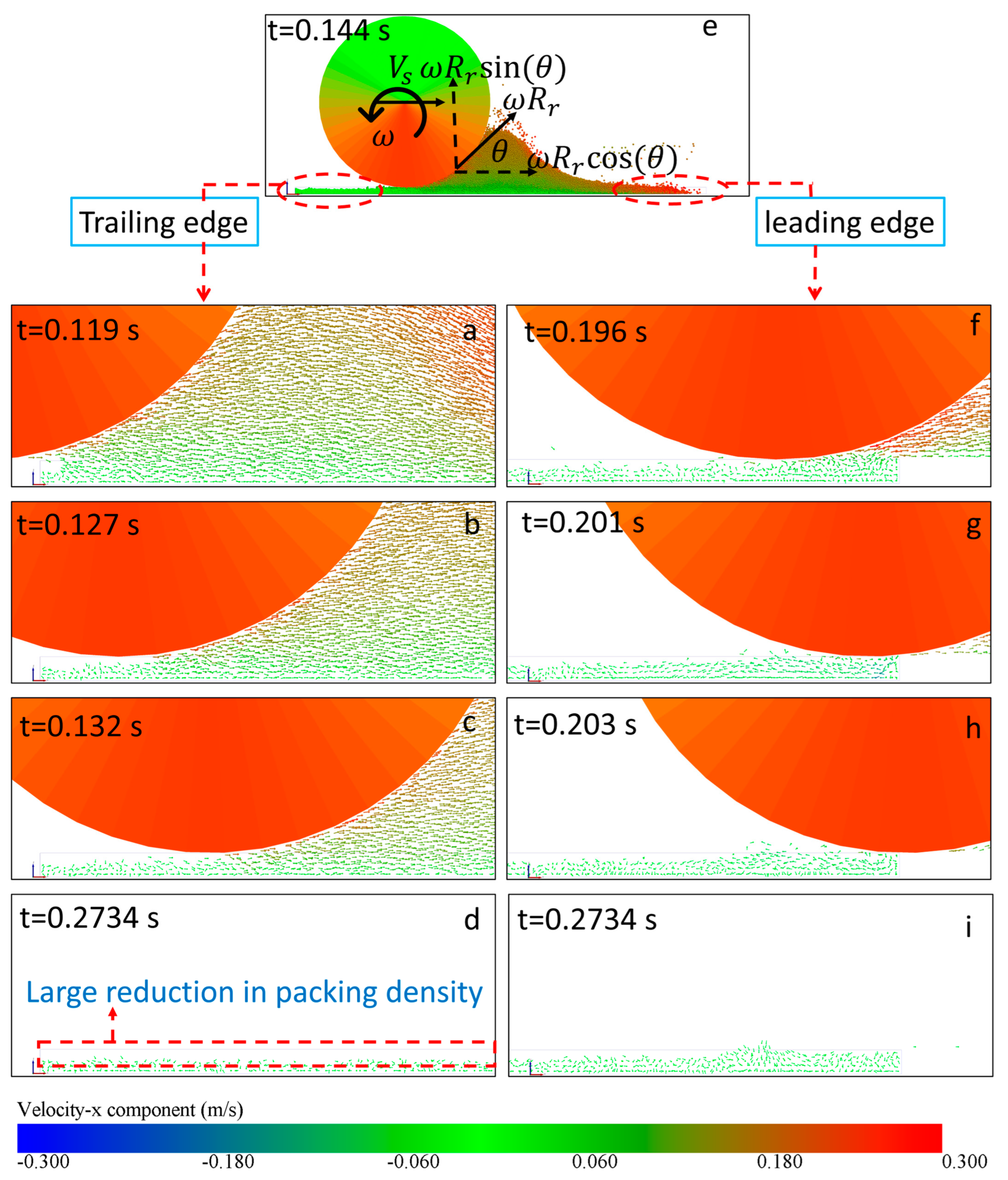
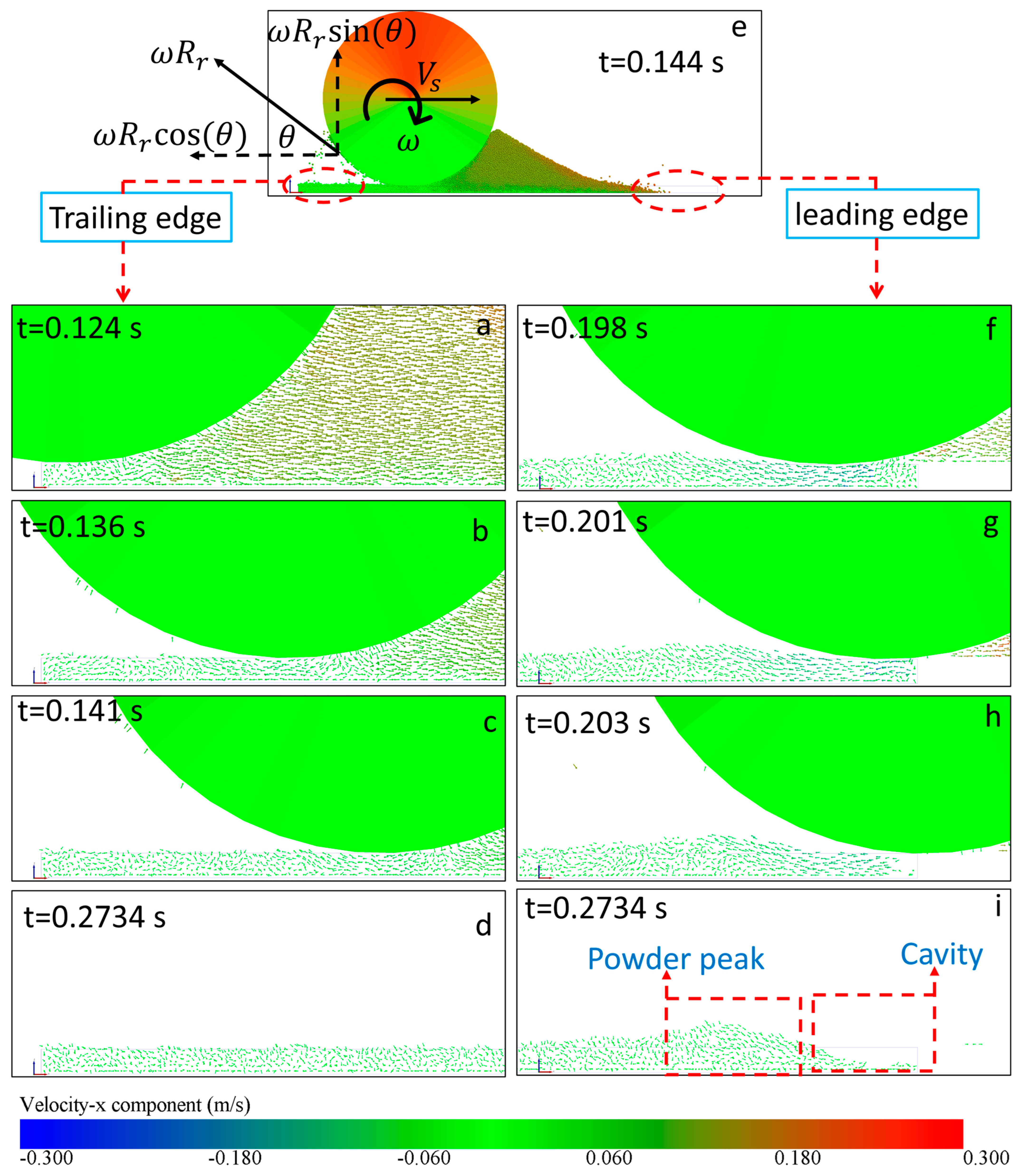
Similar to other roller configurations, as the roller approaches the leading edge, the high-speed powder collides with the solid boundary at the end of the plate. This collision alters the powder’s direction and affects its interaction with the developing powder layer. The roller’s high circumferential speed also pulls additional powder from the heap in front with high momentum, dispersing it in opposite directions, as shown in Figure 10f–i. This activity leads to noticeable powder buildup just before the leading edge and creates a continuous cavity at the leading edge, as shown in Figure 9c. When the spreading speed increases to match the circumferential speed, an equilibrium is established between the momentum transfer from the spreading speed (positive x-component) and the circumferential speed (negative x-component). This balance reduces the size of the cavity at the leading edge, making it discontinuous, as presented in Figure 9d and Figure 11f–i. Therefore, a high spreading speed and a clockwise rotational speed maintain a stable packing density across the building plate.
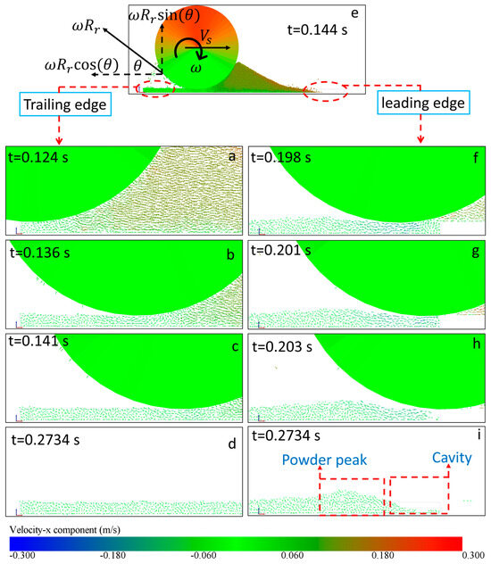
Figure 11.
(a–d,f–i) Velocity vector fields illustrating powder distribution for a forward-rotating roller moving at 0.15 m/s and rotating at 60 rad/s during spreading. Subfigures (a–d) show the development of powder dynamics on the trailing edge (left side) of the building plate over time, while subfigures (f–i) depict the development on the leading edge (right side) over the same time intervals. Subfigure (e) shows the powder heap during the spreading process, with velocity vectors colored by the x-component of velocity, highlighting the flow and heap formation.
3.2. Macroscopic Analysis
3.2.1. Effects of the Spreading Speed on the Macroscopic Properties
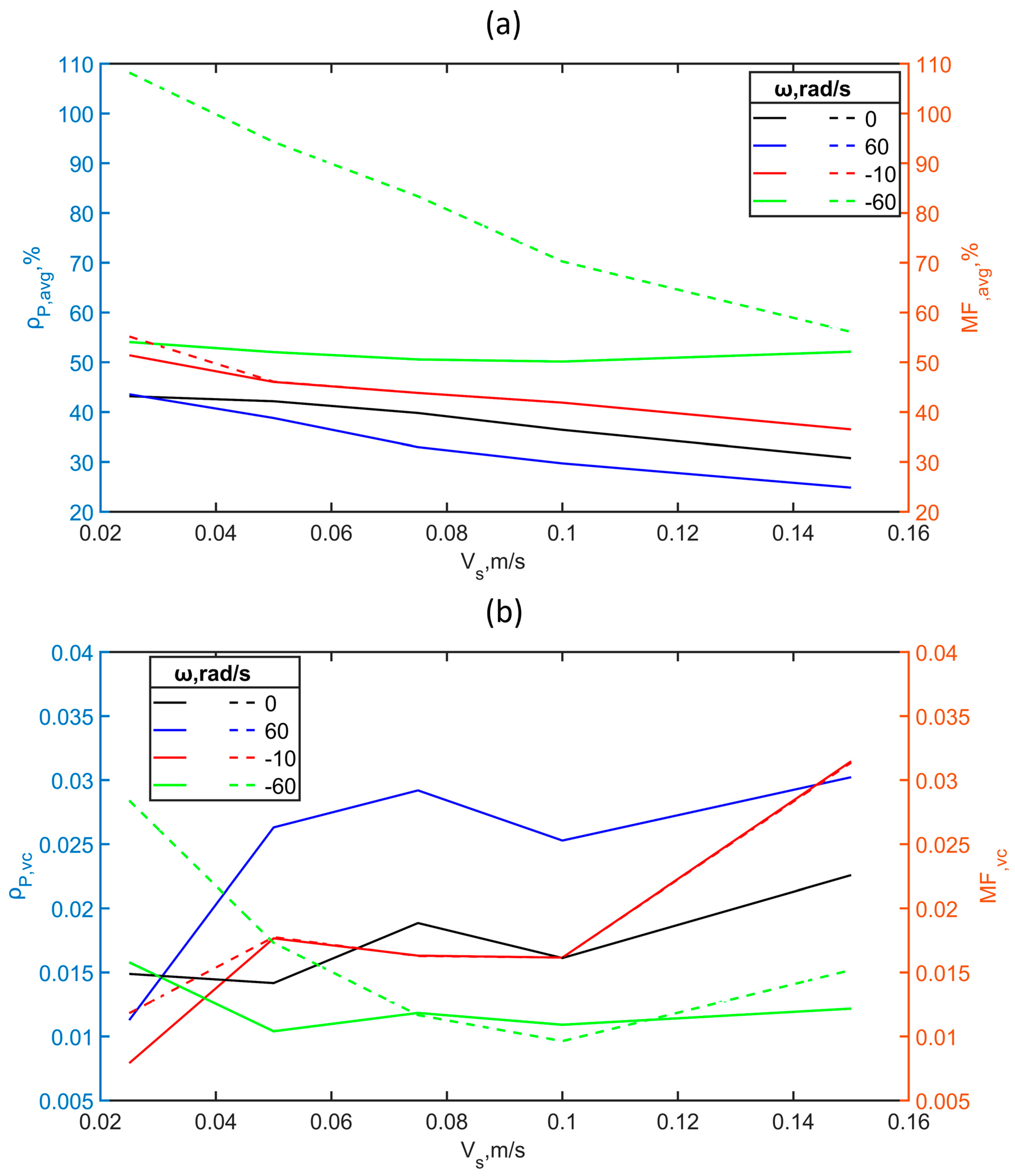
The influence of the spreading speed on macroscopic properties, including packing density, mass fraction, layer thickness, and uniformity, is examined by evaluating these properties’ average values and variations within the study area, highlighted in Figure 1d. The current study shows that the packing density of the powder layer developed by non-rotating and counter-rotating rollers experiences a reduction with increasing spreading speed, a trend that aligns with previous research [17,18,19]. Specifically, as the spreading speed of the non-rotating roller increases from 0.025 to 0.15 m/s, there is a notable reduction in average packing density of 28.7%, as shown in Figure 12. For the counter-rotating roller, rotating at 60 rad/s, the same increase in spreading speed results in a more significant reduction in packing density of 42.8%. Similarly, the sub-rolling roller, rotating at 10 rad/s, shows a 29% reduction in packing density under the same conditions. Conversely, the packing density of the powder layer developed by the super-rolling roller, which rotates at 60 rad/s, fluctuates with a maximum change of only 7%. This result indicates that the clockwise rotation, balanced with the spreading speed, compensates for the reduction in packing density due to the high spreading speed.
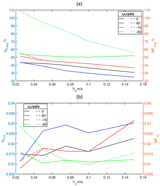
Figure 12.
Packing density and mass fraction characteristics of study zone versus spreading speed for different roller configurations. (a) Average packing density (solid lines) and average mass fraction (dashed lines) and (b) variation coefficient of packing density (solid lines) and mass fraction (dashed lines).
When considering mass fraction, it is essential to note that the layer thickness developed by non-rotating, counter-rotating, and sub-rolling rollers falls below the desired layer thickness. In contrast, the layer thickness developed by super-rolling and rolling rollers exceeds the desired layer thickness. Consequently, the mass fraction is identical to the packing density of non-rotating, counter-rotating, and sub-rolling rollers. At the same time, it exceeds the packing density in the case of rolling and super-rolling rollers. Notably, the mass fraction experiences a reduction of 48.2% when the spreading speed of the super-rolling roller, which rotates at 60 rad/s, increases from 0.025 to 0.15 m/s.
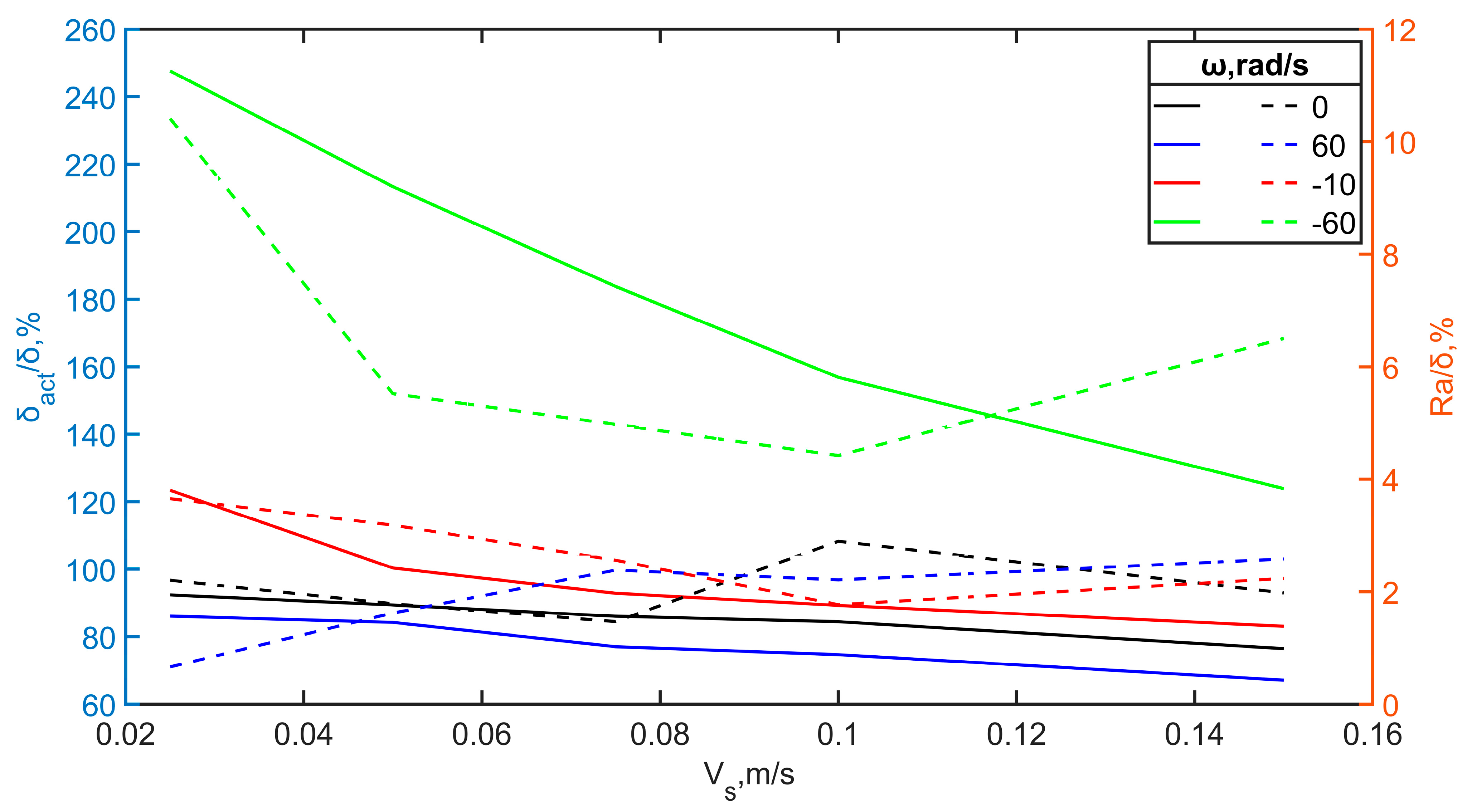
As the spreading speed of the non-rotating roller increases from 0.025 to 0.15 m/s, the average layer thickness decreases by 17.2%, as shown in Figure 13. The counter-rotating roller, rotating at 60 rad/s, also shows a 22% decrease in average layer thickness with the same increase in spreading speed. Moreover, the sub-rolling roller, rotating at 10 rad/s, demonstrates an even more significant reduction in average layer thickness of 32.7%. The layer thicknesses produced by the non-rotating, counter-rotating, and sub-rolling rollers are lower than the desired layer thickness. Conversely, the layer thicknesses produced by the super-rolling and rolling rollers exceed the desired layer thickness. For the super-rolling roller, an increase in spreading speed from 0.025 to 0.15 m/s results in a 50% reduction in layer thickness.
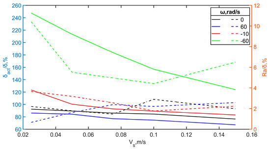
Figure 13.
Average layer thickness and surface roughness of study zone developed by different roller configurations versus the spreading speed.
Non-rotating and counter-rotating rollers maintain a constant level of surface roughness (approximately 2.9% of the desired layer thickness in this study). However, adding clockwise rotational speed to the roller dynamics increases surface roughness (3.7% in the case of sub-rolling and 10.4% in the case of super-rolling). Generally, regardless of the rotational speed and spreading speed, the roller-spreading process is random, maintaining a specific level of variation in the packing density distribution. However, counterclockwise rotation compared to clockwise rotation is better in terms of powder layer uniformity due to the turbulent motion of powder resulting from the clockwise rotational speed (i.e., powder burst).
The enhanced spreading speed in the counter-rotating roller closely mirrors that of the non-rotating roller with more pronounced effects. Likewise, the enhanced spreading speed in the sub-rolling roller closely mirrors that of the non-rotating roller. The behaviors of non-rotating, counter-rotating, and sub-rolling rollers can be explained similarly by understanding momentum transfer from the roller to the particles. When the roller is not rotating (ω = 0) and moves solely with the spreading speed, the majority of the particles attain velocities approximately equal to the spreading speed (). In the case of the counter-rotating roller, the addition of circumferential speed increases the roller’s surface speed, thereby enhancing the particle velocities (). Conversely, with the sub-rolling roller, the circumferential speed acts in the opposite direction, reducing the roller surface speed and consequently lowering the particle velocities (). Despite the reduction, the resultant particle speed remains effective in the direction of spreading. At a high spreading speed, the powder moves away from the left solid boundary of the building plate while being compressed toward the right solid boundary due to the dragging force, indicating the presence of fewer particles. When the spreading speed is high, the particles deposited on the powder bed continue flowing for a specific distance due to the excessive momentum exchanged with the roller. This excessive momentum exchange causes particles to be dragged out of the building plate, reducing the packing density. This considerable transferred momentum leads to more powder disturbance, causing an uneven surface and a reduction in layer thickness. Conversely, particles settle more quickly and uniformly onto the powder bed at low spreading speeds due to the reduced kinetic energy and momentum. This minimized momentum exchange leads to less disturbance of the powder bed, resulting in a more even distribution, higher packing density, smoother surface, more consistent layer thickness, and, unfortunately, longer total printing time. The increased rotational speed of the counter-rotating roller contributes to elevated particle momentum, leading to less densely packed particles, and it is aligned with literature reviews [4,6,13,19,22,23,24]. When a sub-rolling roller moves forward at a spreading speed, it behaves similarly to a non-rotating roller. The increased spreading speed causes the powder to shift from the left side due to its generated momentum. This behavior of a sub-rolling roller is consistent with non-rotating and counter-rotating configurations as long as the circumferential speed remains below the spreading speed. The momentum exchange resulting from the spreading speed plays a more significant role than the momentum induced by the circumferential speed.
Conversely, different behavior is observed when dealing with a super-rolling roller, where the circumferential speed equals or exceeds the spreading speed. The backward circumferential speed component pulls the powder in the opposite direction of spreading. This causes the powder to disperse over the building plate after the roller passes (i.e., powder burst), compensating for the reduction in powder due to the high spreading speed. This compensation helps sustain the packing density despite the high spreading speed, differing from the behaviors observed in non-rotating, counter-rotating, and sub-rolling rollers.
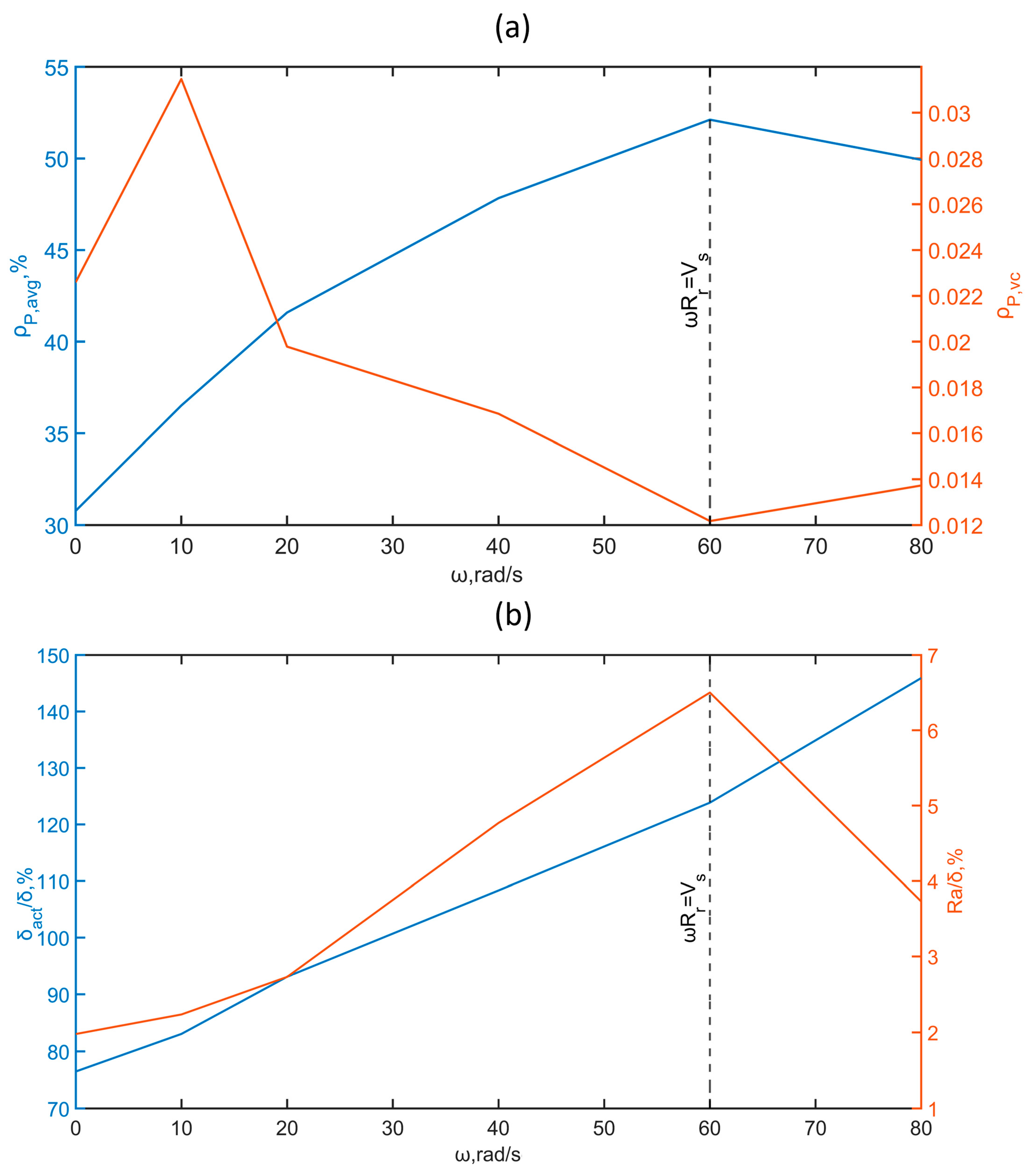
Adopting a high spreading speed for the roller offers advantages in reducing spreading and production times. However, it is essential to recognize that high spreading speeds can decrease packing density and layer thickness. To counteract these effects, considering the behavior of the super-rolling roller explained previously, a higher clockwise rotational speed can be employed to establish a balance between the forward and backward momentum transfers to particles. When a forward-rotating roller dispenses powder at a spreading speed of 0.15 m/s while gradually increasing its rotational speed from zero to the threshold value (), a significant enhancement in packing density is observed. Specifically, the packing density increases by 69.4%, and the layer thickness increases by 62%, as illustrated in Figure 14. This observation supports the notion that the increase in powder quantity due to the occurrence of powder bursts, which are caused by backward momentum transfer to particles, compensates for the reduction in powder amount resulting from the drag effect associated with higher spreading speeds. Furthermore, the increase in packing density is accompanied by a substantial reduction in the coefficient of variation, with a decrease of at least 46%. These findings demonstrate that implementing a higher clockwise rotational speed in conjunction with a high spreading speed can effectively enhance packing density and layer thickness while reducing variability, thus optimizing roller spreading.
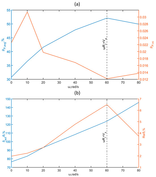
Figure 14.
Macroscopic characteristics of powder layer formed by forward-rotating roller moves at 0.15 m/s versus rotational speed. (a) Packing density and its variation coefficient. (b) Layer thickness and surface roughness.
3.2.2. Effect of the Resultant Speed
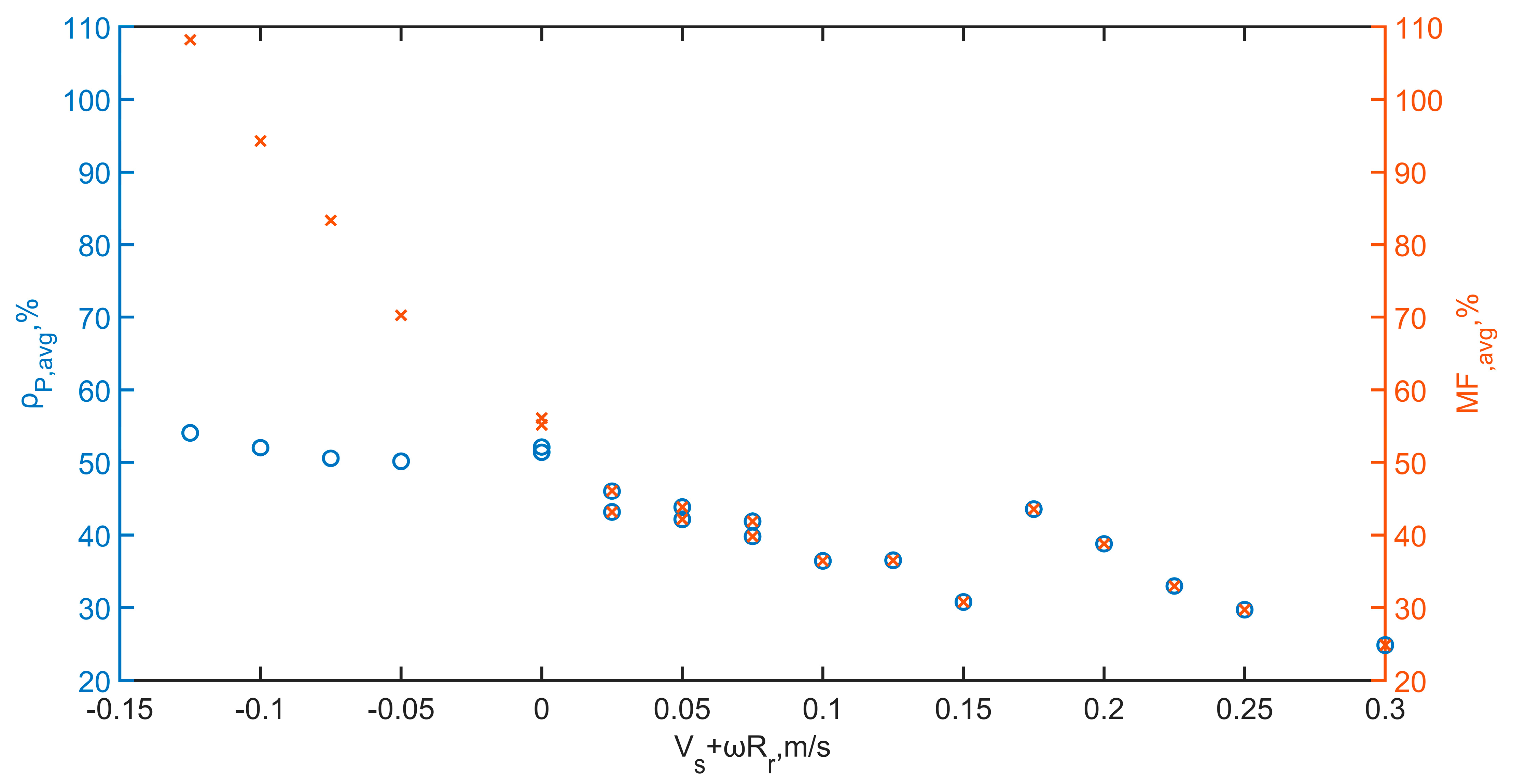
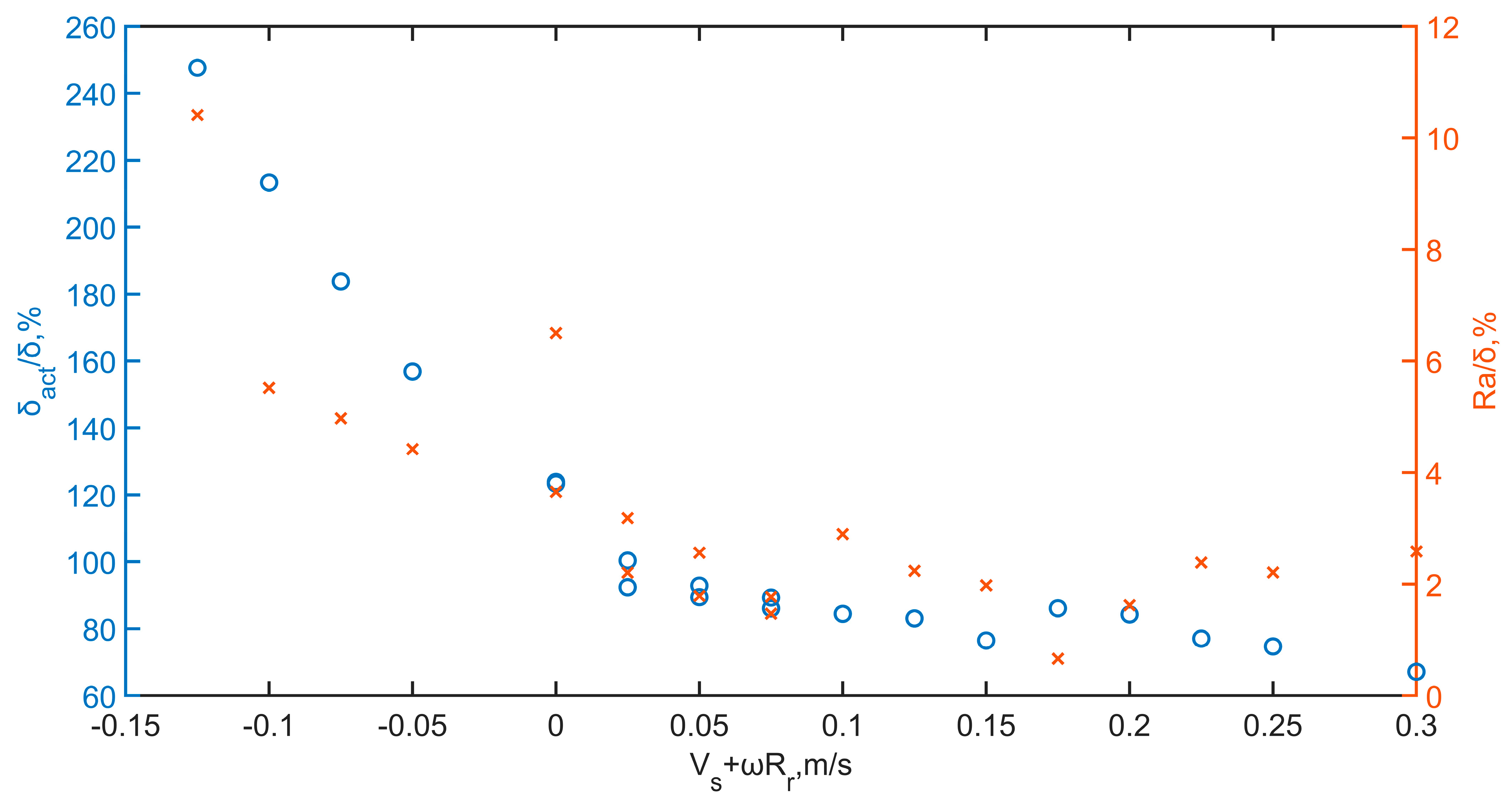
The combined effect of the roller’s translational and rotational motions on the spreading process is examined by considering the resultant speed, which is the sum of the spreading and circumferential speeds. Analysis shows that the packing density remains relatively stable at higher values when the resultant speed is slightly negative or near zero (i.e., super-rolling roller). However, the mass fraction increases rapidly as the resultant speed moves further below zero, as shown in Figure 15. Conversely, as the resultant speed increases past zero, there are noticeable and identical declines in packing density and mass fraction. This trend suggests that higher positive resultant speeds, corresponding to higher spreading speeds or counter-rotating or sub-rolling rollers, adversely affect packing density and the spreader’s ability to distribute powder uniformly over the building plate. The layer thickness decreases as the resultant speed shifts from negative to positive values, as presented in Figure 16. The thickness is the highest when the resultant speed is negative, indicating the effect of powder bursts due to clockwise rotation, and it gradually decreases as the resultant speed becomes positive. In contrast, the surface roughness is relatively high at negative values, and it decreases to almost zero as the resultant speed approaches positive values. This trend suggests that clockwise rotation (negative circumferential speed) results in a higher layer thickness and surface roughness. In contrast, counterclockwise rotation (positive circumferential speed) tends to smooth the surface and reduce the layer thickness. Therefore, achieving an optimal balance between spreading speed and roller rotation is crucial for maintaining a high-quality and efficient powder spreading process.
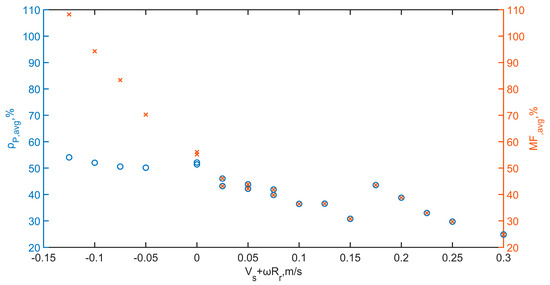
Figure 15.
Average packing density and mass fraction versus the resultant speed.
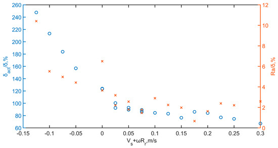
Figure 16.
Average layer thickness and surface roughness versus the resultant speed.
4. Conclusions
Investigating the effects of escalating spreading speeds of various roller configurations on powder bed characteristics has provided valuable insights. The non-rotating and counter-rotating rollers, serving as baselines, exhibit similar trends. An increased spreading speed generally results in decreased packing density and layer thickness. This result occurs because the higher spreading speed transfers more momentum to the particles, dragging the powder off the building plate. With its additional rotational speed, the counter-rotating roller amplifies this effect, causing a more significant reduction in packing density and layer thickness compared to the non-rotating roller. Due to the dominance of spreading speed in the case of a forward-rotating roller at a low clockwise rotational (sub-rolling configuration), it follows a similar trend.
However, the forward-rolling roller at a high clockwise rotational speed (i.e., super-rolling configuration) presents a promising solution. A delicate balance is achieved in this configuration, where the circumferential speed equals or exceeds the spreading speed. This balance effectively manages forward and backward momentum transfers, leading to a powder burst phenomenon compensating for the powder reduction caused by high spreading speeds. This balance reassures us that the packing density and layer thickness can be maintained or even enhanced. The findings show that implementing a higher clockwise rotational speed in conjunction with high spreading speeds can significantly improve the packing density and uniformity of the powder bed. Specifically, a forward-rotating roller operating at a spreading speed of 0.15 m/s, with a gradually increasing rotational speed, enhances the packing density by 69.4% and the layer thickness by 62% while reducing the variation coefficient by 46%. Conversely, the surface roughness increases to 10.4% of the desired layer thickness, and the surface roughness values of other configurations increase to 3.7%.
The study emphasizes optimizing the roller’s combined translational and rotational motions to achieve superior powder bed characteristics. The study lays the groundwork for further exploration into the complex dynamics of roller spreading processes and has immediate applications in enhancing the efficiency and quality of additive manufacturing techniques. Future work can expand on these findings by exploring different material properties, roller designs and dynamics to refine and enhance the powder-spreading process.
Author Contributions
Conceptualization, M.A.S., S.T. and M.E.; methodology, M.A.S., S.T. and M.E.; software, M.A.S.; validation, M.A.S.; formal analysis, M.A.S. and S.T.; investigation, M.A.S. and S.T.; resources, M.A.S., S.T. and M.E.; data curation, M.A.S.; writing—original draft preparation, M.A.S.; writing—review and editing, S.T. and M.E.; visualization, M.A.S.; supervision, S.T. and M.E. All authors have read and agreed to the published version of the manuscript.
Funding
This research received no external funding.
Data Availability Statement
The original contributions presented in the study are included in the article, further inquiries can be directed to the corresponding author.
Conflicts of Interest
The authors declare no conflicts of interest.
References
- Yakout, M.; Elbestawi, M.A.; Veldhuis, S.C. On the Characterization of Stainless Steel 316L Parts Produced by Selective Laser Melting. Int. J. Adv. Manuf. Technol. 2018, 95, 1953–1974. [Google Scholar] [CrossRef]
- Yakout, M.; Cadamuro, A.; Elbestawi, M.A.; Veldhuis, S.C. The Selection of Process Parameters in Additive Manufacturing for Aerospace Alloys. Int. J. Adv. Manuf. Technol. 2017, 92, 2081–2098. [Google Scholar] [CrossRef]
- Fereiduni, E.; Ghasemi, A.; Elbestawi, M. Unique Opportunities for Microstructure Engineering via Trace B4C Addition to Ti-6Al-4V through Laser Powder Bed Fusion Process: As-Built and Heat-Treated Scenarios. Addit. Manuf. 2022, 50, 102557. [Google Scholar] [CrossRef]
- Chen, H.; Chen, Y.; Liu, Y.; Wei, Q.; Shi, Y.; Yan, W. Packing Quality of Powder Layer during Counter-Rolling-Type Powder Spreading Process in Additive Manufacturing. Int. J. Mach. Tools Manuf. 2020, 153, 103553. [Google Scholar] [CrossRef]
- Zhang, J.; Tan, Y.; Xiao, X.; Jiang, S. Comparison of Roller-Spreading and Blade-Spreading Processes in Powder-Bed Additive Manufacturing by DEM Simulations. Particuology 2022, 66, 48–58. [Google Scholar] [CrossRef]
- Zhang, J.; Tan, Y.; Bao, T.; Xu, Y.; Xiao, X.; Jiang, S. Discrete Element Simulation of the Effect of Roller-Spreading Parameters on Powder-Bed Density in Additive Manufacturing. Materials 2020, 13, 2285. [Google Scholar] [CrossRef]
- Lee, Y.; Gurnon, A.K.; Bodner, D.; Simunovic, S. Effect of Particle Spreading Dynamics on Powder Bed Quality in Metal Additive Manufacturing. Integr. Mater. Manuf. Innov. 2020, 9, 410–422. [Google Scholar] [CrossRef]
- Yao, D.; An, X.; Fu, H.; Zhang, H.; Yang, X.; Zou, Q.; Dong, K. Dynamic Investigation on the Powder Spreading during Selective Laser Melting Additive Manufacturing. Addit. Manuf. 2021, 37, 101707. [Google Scholar] [CrossRef]
- Ribeiro, I.; Matos, F.; Jacinto, C.; Salman, H.; Cardeal, G.; Carvalho, H.; Godina, R.; Peças, P. Framework for Life Cycle Sustainability Assessment of Additive Manufacturing. Sustainability 2020, 12, 929. [Google Scholar] [CrossRef]
- Taddese, G.; Durieux, S.; Duc, E. Sustainability Performance Indicators for Additive Manufacturing: A Literature Review Based on Product Life Cycle Studies. Int. J. Adv. Manuf. Technol. 2020, 107, 3109–3134. [Google Scholar] [CrossRef]
- Fouda, Y.M.; Bayly, A.E. A DEM Study of Powder Spreading in Additive Layer Manufacturing. Granul. Matter 2020, 22, 10. [Google Scholar] [CrossRef]
- Meier, C.; Weissbach, R.; Weinberg, J.; Wall, W.A.; Hart, A.J. Critical Influences of Particle Size and Adhesion on the Powder Layer Uniformity in Metal Additive Manufacturing. J. Mater. Process. Technol. 2019, 266, 484–501. [Google Scholar] [CrossRef]
- Shaheen, M.Y.; Thornton, A.R.; Luding, S.; Weinhart, T. The Influence of Material and Process Parameters on Powder Spreading in Additive Manufacturing. Powder Technol. 2021, 383, 564–583. [Google Scholar] [CrossRef]
- Si, L.; Zhang, T.; Zhou, M.; Li, M.; Zhang, Y.; Zhou, H. Numerical Simulation of the Flow Behavior and Powder Spreading Mechanism in Powder Bed-Based Additive Manufacturing. Powder Technol. 2021, 394, 1004–1016. [Google Scholar] [CrossRef]
- Yao, D.; Liu, X.; Wang, J.; Fan, W.; Li, M.; Fu, H.; Zhang, H.; Yang, X.; Zou, Q.; An, X. Numerical Insights on the Spreading of Practical 316 L Stainless Steel Powder in SLM Additive Manufacturing. Powder Technol. 2021, 390, 197–208. [Google Scholar] [CrossRef]
- Lampitella, V.; Trofa, M.; Astarita, A.; D’Avino, G. Discrete Element Method Analysis of the Spreading Mechanism and Its Influence on Powder Bed Characteristics in Additive Manufacturing. Micromachines 2021, 12, 392. [Google Scholar] [CrossRef]
- Xiang, Z.; Zhang, M.; Yan, R.; Yin, Q.; Zhang, K. Powder-Spreading Dynamics and Packing Quality Improvement for Laser Powder Bed Fusion Additive Manufacturing. Powder Technol. 2021, 389, 278–291. [Google Scholar] [CrossRef]
- Yao, D.; Wang, J.; Li, M.; Zhao, T.; Cai, Y.; An, X.; Zou, R.; Zhang, H.; Fu, H.; Yang, X.; et al. Segregation of 316L Stainless Steel Powder during Spreading in Selective Laser Melting Based Additive Manufacturing. Powder Technol. 2022, 397, 117096. [Google Scholar] [CrossRef]
- Wang, L.; Zhou, Z.; Li, E.; Shen, H.; Yu, A. Powder Deposition Mechanism during Powder Spreading with Different Spreader Geometries in Powder Bed Fusion Additive Manufacturing. Powder Technol. 2022, 395, 802–810. [Google Scholar] [CrossRef]
- Phua, A.; Doblin, C.; Owen, P.; Davies, C.H.J.; Delaney, G.W. The Effect of Recoater Geometry and Speed on Granular Convection and Size Segregation in Powder Bed Fusion. Powder Technol. 2021, 394, 632–644. [Google Scholar] [CrossRef]
- Wu, Q.; Qiao, C.; Wang, J.; Yao, D.; Wu, Y.; Fan, W.; Li, M.; An, X. Adaptability Investigations on Bottom Modified Blade in Powder Spreading Process of Additive Manufacturing. Addit. Manuf. 2022, 49, 102477. [Google Scholar] [CrossRef]
- Haeri, S.; Wang, Y.; Ghita, O.; Sun, J. Discrete Element Simulation and Experimental Study of Powder Spreading Process in Additive Manufacturing. Powder Technol. 2016, 306, 45–54. [Google Scholar] [CrossRef]
- Haeri, S. Optimisation of Blade Type Spreaders for Powder Bed Preparation in Additive Manufacturing Using DEM Simulations. Powder Technol. 2017, 321, 94–104. [Google Scholar] [CrossRef]
- Parteli, E.J.R.; Pöschel, T. Particle-Based Simulation of Powder Application in Additive Manufacturing. Powder Technol. 2016, 288, 96–102. [Google Scholar] [CrossRef]
- Seluga, K.J. Three Dimensional Printing by Vector Printing of Fine Metal Powders. Ph.D. Thesis, Massachusetts Institute of Technology, Cambridge, MA, USA, 2001. [Google Scholar]
- Tang, M.; Guo, Y.; Zhang, W.; Ma, H.; Yang, L.; Wei, W.; Wang, L.; Fan, S.; Zhang, Q. On Recoated Powder Quality with a Forward Rotating Flexible Roller in Laser Powder Bed Fusion of 30 wt% 5 μm SiCp/AlSi10Mg Composites. Mater. Des. 2023, 225, 111489. [Google Scholar] [CrossRef]
- Niino, T.; Sato, K. Effect of Powder Compaction in Plastic Laser Sintering Fabrication. In Proceedings of the Solid Freeform Fabrication Symposium 2009, Austin, TX, USA, 3–5 August 2009. [Google Scholar]
- Ziaee, M.; Hershman, R.; Mahmood, A.; Crane, N.B. Fabrication of Demineralized Bone Matrix/Polycaprolactone Composites Using Large Area Projection Sintering (LAPS). J. Manuf. Mater. Process. 2019, 3, 30. [Google Scholar] [CrossRef]
- Gan, J.Q.; Yu, A.B.; Zhou, Z.Y. DEM Simulation on the Packing of Fine Ellipsoids. Chem. Eng. Sci. 2016, 156, 64–76. [Google Scholar] [CrossRef]
- Zhu, H.P.; Zhou, Z.Y.; Yang, R.Y.; Yu, A.B. Discrete Particle Simulation of Particulate Systems: A Review of Major Applications and Findings. Chem. Eng. Sci. 2008, 63, 5728–5770. [Google Scholar] [CrossRef]
- Burman, B.C.; Cundall, P.A.; Strack, O.D.L. A Discrete Numerical Model for Granular Assemblies. Geotechnique 1980, 30, 331–336. [Google Scholar] [CrossRef]
- Mindlin, R.D.; Deresiewicz, H. Elastic Spheres in Contact Under Varying Oblique Forces. J. Appl. Mech. 2021, 20, 327–344. [Google Scholar] [CrossRef]
- Johnson, K.L.; Kendall, K.; Roberts, A.D. Surface Energy and the Contact of Elastic Solids. Proc. R. Soc. Lond. Ser. A Math. Phys. Sci. 1971, 324, 301–313. [Google Scholar] [CrossRef]
- Altair EDEM, 2021.1; Altair Engineering Inc.: Troy, MI, USA, 2021.
- Alizadeh, M.; Asachi, M.; Ghadiri, M.; Bayly, A.; Hassanpour, A. A Methodology for Calibration of DEM Input Parameters in Simulation of Segregation of Powder Mixtures, a Special Focus on Adhesion. Powder Technol. 2018, 339, 789–800. [Google Scholar] [CrossRef]
- Roessler, T.; Katterfeld, A. Scaling of the Angle of Repose Test and Its Influence on the Calibration of DEM Parameters Using Upscaled Particles. Powder Technol. 2018, 330, 58–66. [Google Scholar] [CrossRef]
- Chen, H.; Wei, Q.; Wen, S.; Li, Z.; Shi, Y. Flow Behavior of Powder Particles in Layering Process of Selective Laser Melting: Numerical Modeling and Experimental Verification Based on Discrete Element Method. Int. J. Mach. Tools Manuf. 2017, 123, 146–159. [Google Scholar] [CrossRef]
- Gu, D.; Xia, M.; Dai, D. On the Role of Powder Flow Behavior in Fluid Thermodynamics and Laser Processability of Ni-Based Composites by Selective Laser Melting. Int. J. Mach. Tools Manuf. 2019, 137, 67–78. [Google Scholar] [CrossRef]
Disclaimer/Publisher’s Note: The statements, opinions and data contained in all publications are solely those of the individual author(s) and contributor(s) and not of MDPI and/or the editor(s). MDPI and/or the editor(s) disclaim responsibility for any injury to people or property resulting from any ideas, methods, instructions or products referred to in the content. |
© 2024 by the authors. Licensee MDPI, Basel, Switzerland. This article is an open access article distributed under the terms and conditions of the Creative Commons Attribution (CC BY) license (https://creativecommons.org/licenses/by/4.0/).

