Article

Analysis of Thickness Variation in 2219 Aluminum Alloy Ellipsoid Shell with Differential Thickness by Hydroforming

1
School of Material Science and Engineering, Harbin Institute of Technology, Harbin 150000, China
2
National Key Laboratory of Hot and Precise Forming Process, Harbin Institute of Technology, Harbin 150000, China
*
Author to whom correspondence should be addressed.
Metals 2024, 14(10), 1140; https://doi.org/10.3390/met14101140 (registering DOI)
Submission received: 29 August 2024 / Revised: 3 October 2024 / Accepted: 4 October 2024 / Published: 6 October 2024

Abstract

:
The process of spinning and machining for heavy plates has the problems of a large amount of machining, large springback, and easy cracking. Aiming to address these issues, we proposed a deep drawing forming method for a plate with differential thickness to manufacture an integral ellipsoid component with a thin zone in the middle and a thick zone in the periphery. The plate with a differential thickness was initially produced through machining, followed by the execution of deep drawing deformation. During the deformation process of plates with differential thickness, the thin zone is prone to rupture defects. Therefore, a hydroforming method utilizing an elastic auxiliary plate was adopted to solve this problem. Through mechanical analysis and deep drawing experiments, the influences of hydraulic pressure and elastic auxiliary plate on the distributions of thickness and strain were studied, and the influence of friction on hydroforming was analyzed. The results indicate that increasing the hydraulic pressure and setting elastic auxiliary plates can increase the interfacial friction, reduce the thickness thinning rate, and improve the thickness distribution and deformation uniformity within the thin zone. When the hydraulic pressure is 5.2 MPa and the thickness of the elastic plate is 5 mm, the maximum thickness thinning rate of the ellipsoid shell is 8.8%, which is 34% lower than that of the ellipsoid shell obtained via conventional deep drawing.

1. Introduction

Thin-walled components fabricated from aluminum alloys are applied in the aerospace field extensively, as they possess the advantages of light weight, high strength, and excellent corrosion resistance [1,2]. The dome of the propellant tank in the launch vehicle represents a typical thin-walled, complex curved component with a large size; it is a critical component with stringent performance requirements and challenging manufacturing processes, subjected to intricate loading conditions and extreme environments during operation [3,4,5]. The dome of the propellant tank is usually designed as an ellipsoid shell, which can be obtained with an integral structure or welding structure. Due to constraints imposed by equipment tonnage and blank size, the dome is predominantly manufactured in a welding structure consisting of multiple petals [6]. The presence of numerous welding seams results in disadvantages such as low dimensional accuracy, large springback, and large residual stress, which severely compromise the reliability of the components. An integral dome can be achieved through the hydroforming method without wrinkling and rupture defects, and the welding seams between the petals can be eliminated [7]. However, the circumferential welding seam between the dome and the fork ring still cannot be eliminated, which may lead to significant welding residual stress, the low reliability of the welding seam, and potential safety hazards [8]. Through a process route involving hot spinning and computer numerical control (CNC) milling, an integral structure dome can be produced [9]. This manufacturing method necessitates highly specialized equipment and entails a complex process and a long manufacturing cycle. Additionally, it also has the limitations of substantial machining requirements, low material utilization, considerable springback, and a risk of cracking.
For components with such structural characteristics, a forming method utilizing an aluminum alloy plate with differential thickness is adopted for the fabrication of an integral thin-walled surface component with differential thickness. The plate features a thin zone in the middle and a thick zone in the periphery, which are designated for forming the dome and the fork ring, respectively. Thus, the integral manufacturing of the dome and the fork ring can be realized in a single deep drawing deformation process. This processing route can eliminate the circumferential welding seam between the dome and the fork ring, thereby avoiding residual welding stress. Moreover, it can cut down the volume of machining in subsequent stages, reduce the amount of springback, and shorten the production cycle, which can fundamentally improve the properties and reliability of the component.
Different from the traditional tailor-weld blanks and tailor-rolled blanks [10,11,12], the thickness transition zone of the differential thickness plate used in this work is annular, and the plate is in a complex stress state of deep drawing deformation. Due to the thickness difference in different zones of this kind of plate, stress concentration is more likely to occur in the thin zone during the deformation process, which can result in poor deformation uniformity, excessive local thinning, and a great risk of rupture. To address the forming difficulties of plates with such structural characteristics, hydroforming was adopted—combined with an elastic auxiliary plate set on the lower surface of the aluminum alloy plate—to increase the forming limit of the plate with differential thickness. Hydroforming is an advanced sheet forming process, which is suitable for thin-walled curved components with poor plasticity and complex structures [13,14]. It can effectively increase the forming limit of the sheet [15,16] and improve the forming accuracy and deformation uniformity of components [17,18]. As a highly elastic material, polyurethane can play a good auxiliary role in plastic deformation, such as a flexible soft die in a multi-point sandwich forming process, a support mandrel in tube deformation, or a self-sealing role in hydroforming [19,20,21].
In summary, for the purpose of studying the thickness variation in the thin zone during the forming process, the ellipsoid shell with a differential thickness was selected as the research object, and the hydroforming experiment of an annealed 2219 aluminum alloy plate with a differential thickness was conducted. Combined with mechanical analysis, the effects of hydraulic pressure and elastic auxiliary plate on the distributions of thickness and strain were studied, and the influence of friction on hydroforming in the deformation process was analyzed. In the hydroforming experiment, a differential thickness ellipsoidal shell with a relatively ideal thickness distribution was successfully obtained, validating the feasibility of the integral deep drawing of plates with differential thickness. The results of this work provide a basis for the integral deep drawing of components with differential thicknesses and expand new ideas for the fabrication of complex thin-walled components.

2. Experimental Section

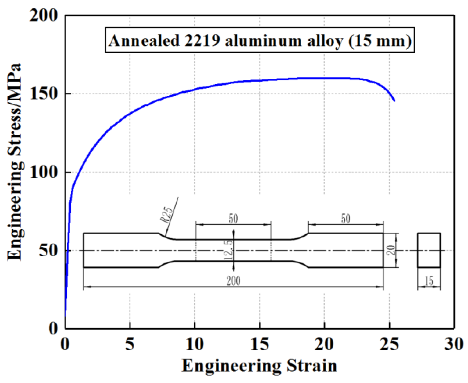
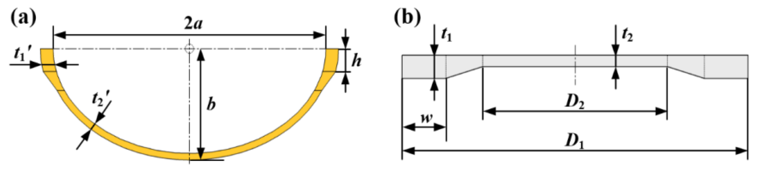
2.1. Sheet Material and Ellipsoid Shell Size

Annealed 2219 aluminum alloy sheet with a thickness of 15 mm was selected for this experiment. The uniaxial tensile tests were conducted in accordance with ASTM E8/E8M-21 [22]. The tensile specimens with dimensions of 50 mm gauge length and 12.5 mm gauge width were cut from the initial sheet by wire-electrode cutting, and the tensile direction was parallel to the rolling direction. The initial strain rate was 1.0 × 10⁻³ s−1. The engineering stress–strain curve obtained by uniaxial tensile tests is shown in Figure 1, and the basic mechanical properties of the material are shown in Table 1.
The target part and the corresponding plate with differential thickness are shown in Figure 2. The target-drawn part is an ellipsoid shell characterized by a thin middle zone and a thick periphery zone. The semi-major axis a and the semi-minor axis b of the ellipsoid shell measure 375 mm and 267.85 mm, respectively. The vertical dimension of the thick zone h should exceed 45 mm. The thickness of the thickness zone and the thin zone are t1 and t2, respectively. The thickness ratio λ is defined as follows:
λ = t 2 / t 1 ,
For the target shell in this work, the thickness of the thin zone t2 was 7.5 mm, the thickness of the thick zone t1 was 15 mm, and the thickness ratio was 1/2. To ensure the proper dimensions of the thick zone of the ellipsoid shell, a plate with differential thickness was designed, as shown in Figure 2b. The overall diameter of the circular differential thickness plate D1 was 1050 mm, the diameter of the middle thin zone D2 was 610 mm, and the radial width of the outer edge thick zone w was 105 mm. The thin zone and the thick zone were connected by a beveled transition.

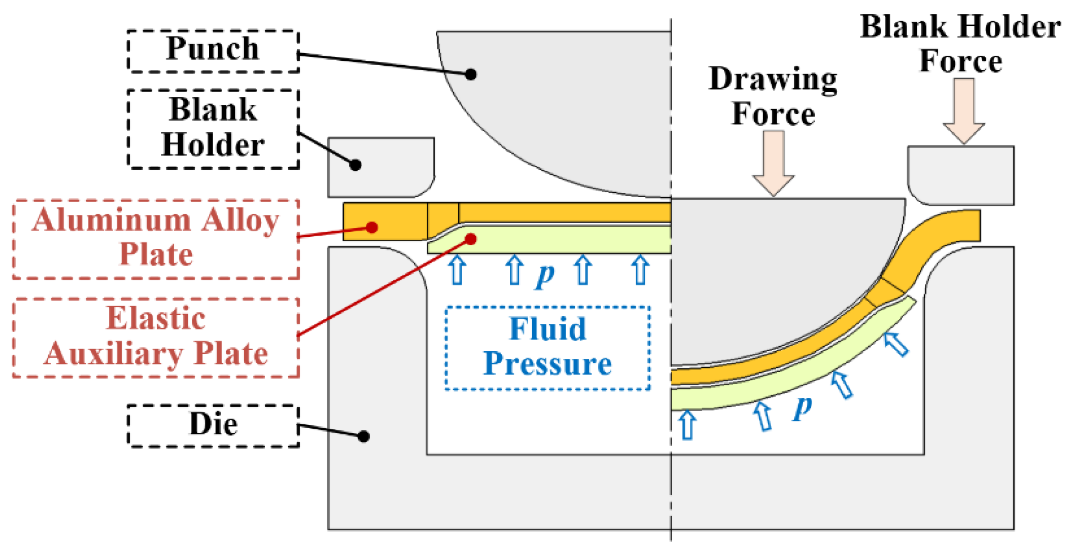
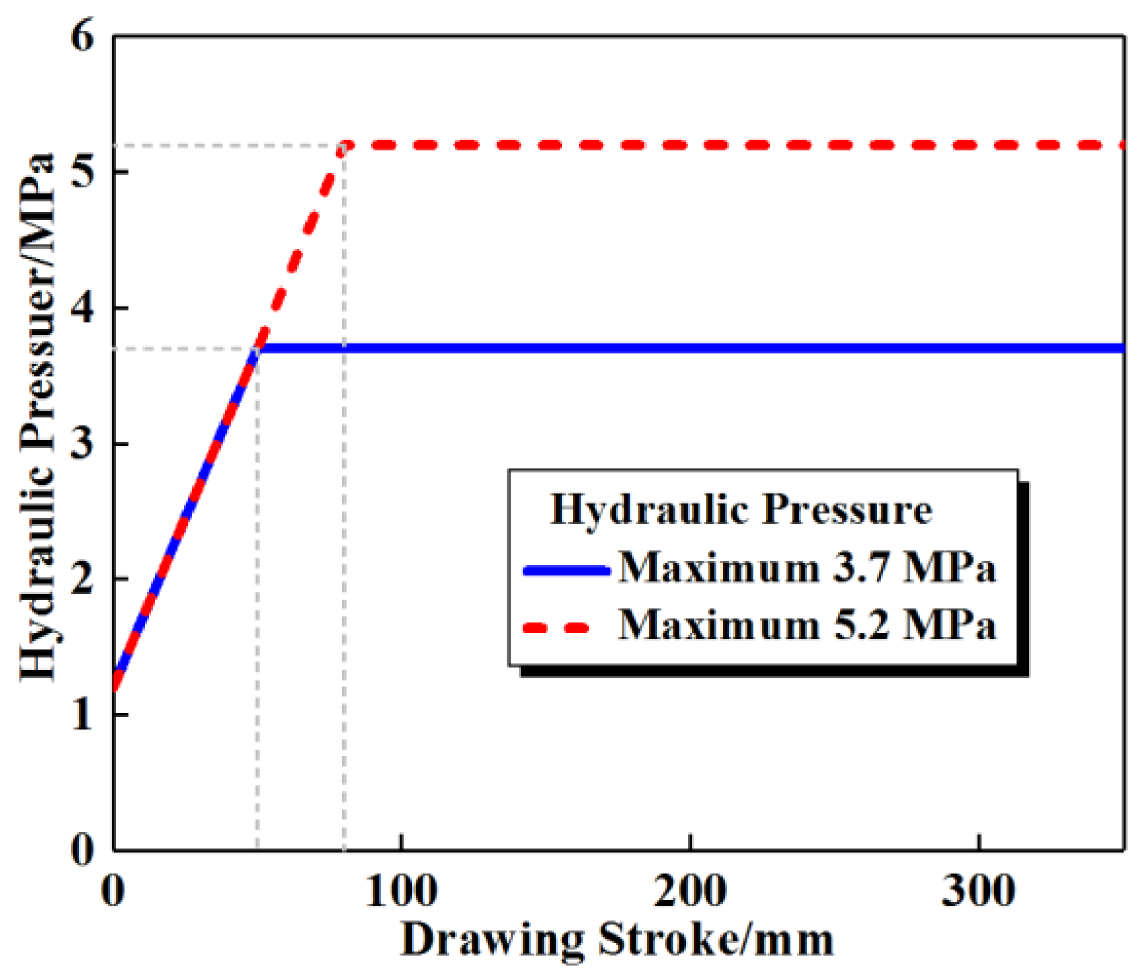
2.2. Hydroforming Process of Plates with Differential Thickness

A schematic diagram of the hydroforming process of aluminum alloy plate with differential thickness is shown in Figure 3. Polyurethane was selected as the elastic auxiliary plate, with a thickness of 5 mm and a diameter of 840 mm, which could completely cover the thin zone and thickness transition zone. A Shore durometer (LX-A) (Dongguan Jingru Measuring Instrument Technology Co., Ltd, Dongguan, China) was employed to measure at five distinct positions on the polyurethane plate. Three measurements were conducted at each position, and the average of all the measurement results was calculated to determine that the Shore hardness of the polyurethane plate was HA85. Prior to conducting the deep drawing experiment, the polyurethane plate was first affixed to the lower surface of the aluminum alloy blank with tape, and the two were placed in the mold as a whole. During the deep drawing process, the polyurethane plate was placed at the lower surface of the aluminum alloy plate and was deformed synergistically with the aluminum alloy plate. Specifically, the aluminum alloy plate was plastically deformed, while the polyurethane plate was elastically deformed. Under the action of hydraulic pressure, the polyurethane plate and the aluminum alloy plate were pressed together, and interfacial friction existed between the two.

2.3. Setup and Procedure

An 8000 kN double-acting hydraulic press (Hefei Metalforming Intelligent Manufacturing Co., Ltd, Hefei, China) was selected for the deep drawing experiments. This hydraulic press facilitates the coordinated control of the drawing slider and the blank holder slider. The movement speeds of the sliders can be adjusted between 0.5 and 100 mm/s, and the maximum drawing force and blank holder force capabilities reach 5000 kN and 3000 kN, respectively. The punch was driven by the drawing slider, descending at a speed of 1 mm/s, and the preset blank holder force was applied under the action of the blank holder slider.
In this work, conventional deep drawing (CDD) and hydroforming experiments were conducted, and two different hydraulic loading paths were designed with the maximum hydraulic pressures of 3.7 MPa and 5.2 MPa. The hydraulic loading paths are shown in Figure 4. The total drawing stroke was 350 mm.

3. Thickness and Strain Distributions

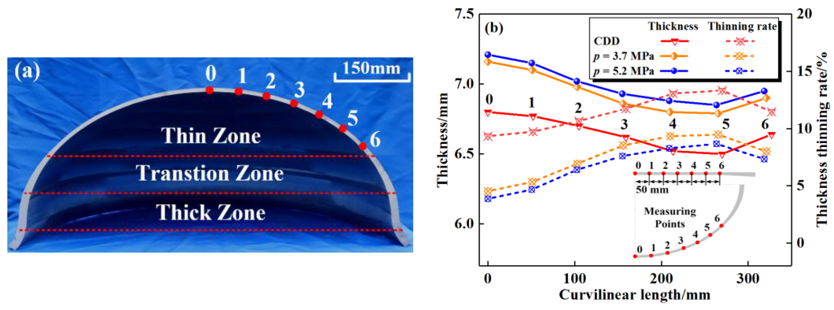
3.1. Thickness Distributions

The deep drawing experiments were carried out in accordance with the above experimental procedures. The ellipsoid shells with differential thickness obtained via hydroforming under different hydraulic pressures are presented in Figure 5. The drawing depth of the ellipsoid shells is 350 mm, and the height of the outer edge thick zone in the vertical direction exceeded the design requirement of 45 mm.
The obtained ellipsoid shells were cut in half, and the thickness at each measuring point was measured via a vernier caliper with an accuracy of 0.02 mm. Figure 6a demonstrates the section diagram of the drawn ellipsoid shell with differential thickness, clearly revealing the thin zone, thickness transition zone, and thick zone from interior to exterior. The thickness thinning rate is a critical parameter to evaluate the quality of this kind of thin-walled component. The measuring points were drawn every 50 mm in the radial direction on the differential thickness plate prior to deformation in order to obtain the thickness distribution within the thin zone, and the measuring points were 0 to 6 in order from the center to the outside. The thicknesses and thickness thinning rates at each measuring point are shown in Table 2.
The thickness distributions and thinning rates within the thin zone at different hydraulic pressures are shown in Figure 6b. With the increase in hydraulic pressure, the overall thickness thinning rate within the thin zone decreases. Under the condition of CDD, the thinnest position is located at point 5 with a maximum thickness thinning rate of 13.3%. For hydroforming, the thinning positions are located at point 5 as well. The maximum thickness thinning rates are 9.6% and 8.8%, respectively, at the hydraulic pressures of 3.7 MPa and 5.2 MPa, which are 28% and 34% lower than those of CDD. The minimum thickness thinning rates occur at the pole (point 0) with the values of 9.3%, 4.5%, and 4.0%, respectively, at the hydraulic pressures of 0 MPa (corresponding to CDD), 3.7 MPa, and 5.2 MPa.

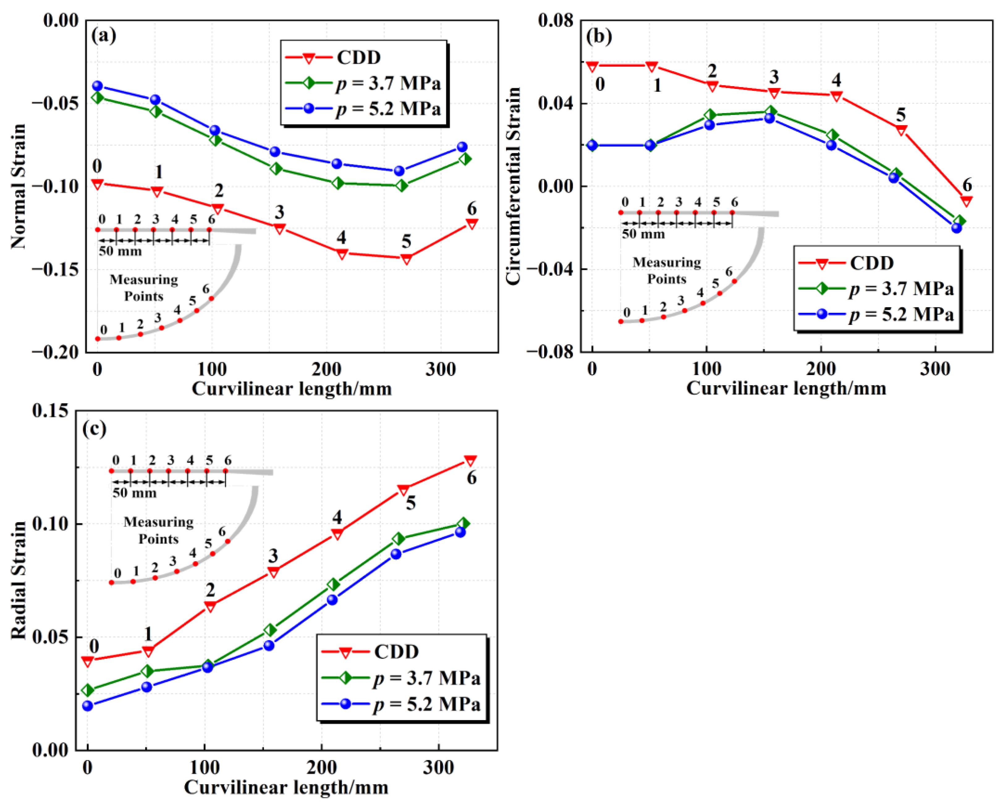
3.2. Strain Distributions

Following the plastic deformation of the aluminum alloy plate, the thickness t at each measuring point on the drawn ellipsoid shell was measured and compared with the initial thickness of the thin zone t2. The normal strain εt of each measuring point can be expressed as follows [23]:
ε t = ln t / t 2 ,
By determining the radius r of each measuring point and comparing it with the initial radius r0, the circumferential strain εθ of each measuring point can be calculated as follows:
ε θ = ln r θ / r 0 θ = ln r / r 0 ,
In accordance with the volume constant condition, the radial strain εφ of each measuring point can be obtained as follows:
ε φ = ε t + ε θ ,
Point 0 in Figure 6a is the center of the blank and the drawn part, and the radius of point 0 is always 0. Thus, the circumferential strain at this point cannot be obtained by measuring the variation in the radius. In the process of deep drawing, crack and wrinkle defects usually occur in the unsupported zone [24,25], and the requirement for strain accuracy at the pole (point 0) is relatively low. Since the strain components at point 0 and point 1 are relatively close, the circumferential strain at point 0 and point 1 are roughly considered to be equal, thereby completing the strain−length curve. The calculation results of strain components at each measuring point via the above equations are given in Table 3. The calculated strain components within the thin zone of the drawn ellipsoid shells under different hydraulic pressures are presented in Figure 7.
The distributions of normal strain within the thin zone calculated via Equation (2) are shown in Figure 7a. As the hydraulic pressure increases, the overall normal strain in the thin zone gradually increases, that is, the absolute value of the normal strain is smaller, which corresponds to a smaller thickness thinning rate. For the drawn ellipsoid shells under different hydraulic pressures, the minimum normal strain occurs at point 5, while the maximum value is located at the pole of the ellipsoid shell. For the drawn ellipsoid shell obtained via CDD, the minimum normal strain reaches −0.143. When the hydraulic pressures are 3.7 MPa and 5.2 MPa, the maximum normal strains in the thin zone are −0.101 and −0.092, respectively, with a decrease of 29% and 36% in absolute value compared with the ellipsoid shell obtained by CDD.
The distributions in circumferential strain within the thin zone obtained by Equation (3) are shown in Figure 7b. The overall circumferential strain in the thin zone decreases with the increase in hydraulic pressure. For the drawn ellipsoid shell under CDD, the maximum circumferential strain in the thin zone is 0.058 at the pole, which shows a decreasing trend from the center to the outside. The circumferential strain at point 6 is negative, indicating that there is a point between points 5 and 6 as a plane strain state. For the drawn ellipsoid shells with hydraulic pressures of 3.7 MPa and 5.2 MPa, the maximum circumferential strain in the thin zone is located at point 3, and the maximum values are 0.036 and 0.033, respectively. Similar to the CDD–ellipsoid shell, the minimum circumferential strain in the thin zone of the drawn ellipsoid shells obtained via hydroforming is also found at point 6 and remains negative. However, with the increase in hydraulic pressure, it can be found that the radius of the plane strain point gradually decreases, implying that there is a larger area of material in the tensile and compressive strain state.
The distributions in radial strain within the thin zone calculated using Equation (4) are shown in Figure 7c. As can be seen, with the increase in hydraulic pressure, the overall radial strain within the thin zone decreases. Under different deformation conditions, the maximum radial strain occurs at point 6, which is situated near the thickness transition zone. When the hydraulic pressures are 0 MPa, 3.7 MPa, and 5.2 MPa, the maximum radial strain values in the thin zone of the drawn ellipsoid shells are 0.128, 0.100, and 0.098, respectively. When the hydraulic pressures are 3.7 MPa and 5.2 MPa, the maximum radial strain in the thin zone is reduced by 22% and 23%, respectively, compared with that of the CDD–ellipsoid shell.

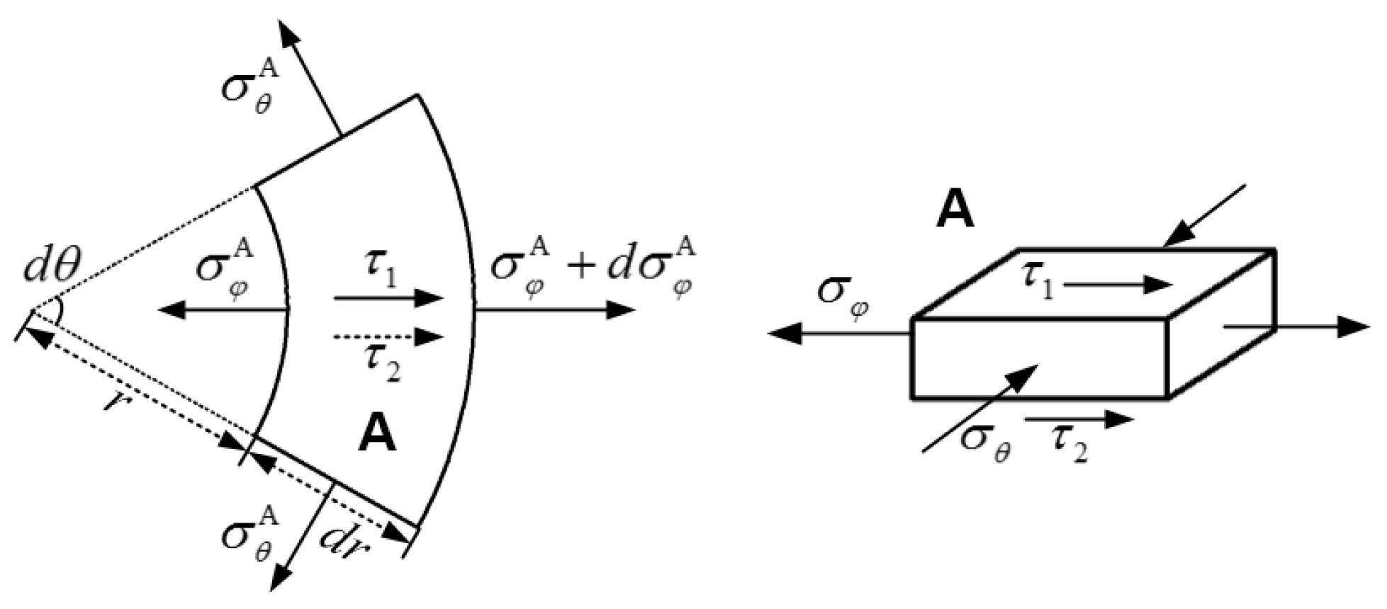
4. Mechanical Analysis of the Influence of Friction on Hydroforming

In order to evaluate the influence of friction on hydroforming, a mechanical model was established for the aluminum alloy plate with differential thickness and polyurethane elastic auxiliary plate, the stress components of the plates were solved, and the deformation states were analyzed. The thickness of the thick zone t1 was 15 mm, and the diameter of the circular differential thickness plate D1 was 1050 mm. Consequently, the thickness-to-diameter ratio was t1/D1 = 1/70, and the target ellipsoid shell can be considered a thin shell from an engineering perspective. It is generally accepted that thin shells are merely subjected to membrane stress, and the magnitudes of the bending stress and normal stress are far smaller than the in-plane stress, having almost no influence on the calculation results and, thus, can be neglected. To simplify the mechanical model, the following assumptions were made:
  • The unsupported zone is not deformed under the action of hydraulic pressure, and the shape of the unsupported zone is approximately a cone;
  • During the deformation process, the thickness of the thick zone is assumed to maintain a constant value of t1 [26,27];
  • The bending effect and the normal stress of the plate are ignored, and the plate is in a state of plane stress [28,29];
  • The material of the plate is an elastic–perfectly plastic material;
  • The deformation is a simple loading process.
The mechanical model of force analysis is shown in Figure 8. The differential thickness aluminum plate can be divided into three parts, including a flange zone (thick zone), an unsupported zone (thickness transition zone), and an attached zone (thin zone). Points A, B, C, and D are taken from the flange zone, the die corner, the outside of the attached boundary, and the attached zone, respectively. The mechanical analysis of these three parts is carried out and the stress components within each part are solved as follows.
An element is taken at point A within the flange zone, as shown in Figure 9. In accordance with Coulomb law of friction [30], the interfacial shear stresses within the flange zone can be expressed as follows:
τ 1 = q μ 1 ,   τ 2 = q μ 2 ,
where q denotes the blank holder force per unit area; μ1 and μ2 represent the Coulomb friction coefficients between the aluminum plate and the blank holder and the aluminum plate and the die, respectively. The equilibrium equation at point A is shown below:
d σ φ A + d r r σ φ A σ θ A + τ 1 + τ 2 t 1 d r = 0 ,
where σ φ A and σ θ A denote the radial stress and circumferential stress, t1 is the thickness within the thick zone, and r represents the radius of point A.
The sequence of principal stresses at point A can be determined as follows:
σ 1 = σ φ A > 0 ,   σ 2 = σ t = 0 ,   σ 3 = σ θ A < 0 ,
In accordance with the Tresca yield criterion [31],
σ 1 σ 3 = σ φ A σ θ A = σ s ,
where σs denotes the yield stress. For the purpose of simplifying the yield behavior of the material, it is assumed that the material is an elastic–perfectly plastic one, disregarding the influence of strain hardening on the yield behavior so as to make the mechanical analysis results more concise and intuitive.
The current outer radius of the aluminum plate is denoted as R, and the boundary condition is assumed as σφ = 0 when r = R. By combining Equations (6) and (8), the radial stress and circumferential stress at point A with any radius r can be expressed as below:
σ φ A = σ s ln R r + R r t 1 q μ 1 + q μ 2 ,
σ θ A = σ s ln R r 1 + R r t 1 q μ 1 + q μ 2 ,
By substituting the radius of point B (rB) into Equations (9) and (10), the stress components at point B can be written as follows:
σ φ B = σ s ln R r B + R r B t 1 q μ 1 + q μ 2 ,
σ θ B = σ s ln R r B 1 + R r B t 1 q μ 1 + q μ 2 ,
Within the flange zone, the direction of the interfacial friction acting on the plate is the same as that of the radial stress. Therefore, the interfacial frictional force in this zone will increase the magnitude of the radial stress of the aluminum alloy plate, which is disadvantageous from the perspective of preventing rupture defects. In actual production, it is commonly selected to reduce the blank holding force or to decrease the friction coefficient through lubrication in order to reduce the interfacial friction within this zone. Nevertheless, this is accompanied by a higher risk of wrinkling or the inability to maintain the hydraulic pressure within the die.
As shown in Figure 10, the unsupported zone between points B and C is taken as the analysis object, and the width of the thickness transition zone is ignored. In accordance with Coulomb law of friction, the interfacial shear stress between aluminum plate and polyurethane plate is expressed as follows:
τ PU = p μ PU ,
where μPU denotes the Coulomb friction coefficient between the aluminum plate and polyurethane plate, and p represents the hydraulic pressure. Thus, the force balance along the generatrix can be written as follows:
2 π r C t 2 σ φ C + 2 π r C l p μ PU = 2 π r B t 1 σ φ B ,
where l represents the generatrix length of the thin zone within the unsupported zone, and rB and rC indicate the radii of points B and C. Thus, the radial stress at point C is shown as below:
σ φ C = t 2 t 1 r B r C σ φ B l μ PU t 2 p ,
Substituting the thickness ratio λ and the radial stress at point B into Equation (15) produces the following:
σ φ C = 1 λ r B r C σ φ B l μ PU t 2 p = 1 λ r B r C σ s ln R r B + R r B t 1 q μ 1 + q μ 2 l μ PU t 2 p ,
For the unsupported zone, the thin zone of the aluminum alloy plate is subjected to interfacial shear stress from the polyurethane plate, and the direction of this interfacial shear stress is opposite to that of the radial stress at point B. It can be known from Equation (16) that the interfacial friction between the polyurethane plate and the aluminum alloy plate can reduce the radial stress at point C. During the process of hydroforming, the polyurethane plate and the aluminum alloy plate deform synergistically, and interfacial friction always exists between the two.
An element between points C and D is taken with an arc length of ∆l, as shown in Figure 11. Then, in accordance with Coulomb law of friction, the interfacial shear stress between the aluminum plate and punch is expressed as below:
τ P = p μ P ,
where μP represents the Coulomb friction coefficient between the aluminum plate and punch. The force balance along the radial direction is shown as follows:
σ φ D 2 π r D t 2 D = σ φ C 2 π r C t 2 C 2 π r C Δ l p μ P + p μ PU ,
Thus, the radial stress at point D can be written as follows:
σ φ D = r C r D t 2 C t 2 D σ φ C r C r D Δ l t 2 D p μ P + p μ PU = r C r D t 2 C t 2 D 1 λ r B r C σ s ln R r B + R r B t 1 q μ 1 + q μ 2 l μ PU t 2 p r C r D Δ l t 2 D p μ P + p μ PU ,
The sequence of principal stresses at point D can be determined as follows:
σ 1 = σ φ D > 0 ,   σ 2 = σ θ D > 0 ,   σ 3 = σ t = 0 ,
In accordance with the Tresca yield criterion,
σ 1 σ 3 = σ φ D = σ s ,
For CDD, since the hydraulic pressure p is 0, the radial stress at point D can be expressed as σ φ D = r C r D t 2 C t 2 D σ φ C , and the value of the coefficient r C r D t 2 C t 2 D is approximately considered to be 1. Consequently, the radial stresses at points C and D are equal to the yield stress σs, and both points are in a plastic state.
It can be known from Equation (19) that the difference in radial stress between points D and C is influenced by several parameters, including geometric parameters, hydraulic pressure, and friction coefficients. The element between points C and D experiences interfacial shear stress on its upper and lower surfaces exerted by the punch and the polyurethane plate, respectively, and the directions of both are opposite to the radial stress direction at point C. For hydroforming, the hydraulic pressure p is greater than 0. Consequently, the radial stress at point D is lower than that at point C, and the difference between the two increases with an increase in arc length ∆l, hydraulic pressure p, and friction coefficients μP and μPU. In accordance with the Tresca yield criterion, the radial stress at point D is less than the yield stress during hydroforming, implying that point D no longer meets the yield condition and is in an elastic state [32].
Within the unsupported and attached zones, the direction of the interface frictional force acting on the aluminum alloy plate is opposite to that of the radial stress, which can reduce the magnitude of the radial stress within these areas. When the friction coefficient is constant, the sliding friction is directly proportional to the normal positive force. In this study, as the hydraulic pressure rises, the magnitude of the interfacial friction becomes larger, and the magnitude of the radial stress becomes smaller. When the hydraulic pressure increased from 3.7 MPa to 5.2 MPa, the maximum thickness thinning rate of the drawn part decreased from 9.6% to 8.8%.
However, the hydraulic pressure cannot be increased without limit. Hydroforming has higher requirements for equipment. Excessive liquid pressure will lead to an excessive reaction force, which is highly likely to exceed the bearing capacity of the equipment. The liquid pressure filling process requires higher equipment requirements, and excessive liquid pressure may result in excessive liquid reaction force, which is likely to exceed the bearing capacity of the equipment. For example, in this study, the drawing force increased by about 1000 kN when the hydraulic pressure was increased from 3.7 MPa to 5.2 MPa.
The interfacial friction between the aluminum plate and the punch occurs within the attached zone, while the interfacial friction between the aluminum plate and polyurethane plate is present throughout the entire thin zone. During the deformation process, although the values of interfacial shear stress are not large compared with the radial stress, it can alter the deformation state of the aluminum plate. As a result, the material is unloaded from the plastic state back to the elastic state. This interfacial friction can inhibit excessive thinning of the aluminum plate and improve the thickness distribution and deformation uniformity.

5. Conclusions

In this work, the formability of an annealed 2219 aluminum alloy plate with differential thickness was studied. Polyurethane was used as an elastic process auxiliary plate to enhance the interfacial friction. Deep drawing experiments were conducted under different hydraulic loading paths, and the distributions of thickness and strain within the thin zone of the drawn ellipsoid shells were analyzed. Combined with mechanical analysis, the influence of interfacial friction on hydroforming was elucidated. The specific conclusions derived from the study are as follows:
(1)
Compared with conventional deep drawing, hydroforming can improve the thickness distribution within the thin zone of the differential thickness plates. With the increase in hydraulic pressure, the overall thickness thinning rate within the thin zone of the drawn ellipsoid shell decreases. When the hydraulic pressures are 0, 3.7 MPa, and 5.2 MPa, the maximum thickness thinning rates are 13.3%, 9.6%, and 8.8%, respectively.
(2)
With the increase in hydraulic pressure, the radial strain and circumferential strain in the thin zone will both decrease, along with the absolute value of the normal strain. Consequently, the overall degree of plastic deformation in the thin zone will also be reduced.
(3)
During hydroforming, the occurrence of interfacial shear stress between the aluminum plate and the elastic auxiliary plate and the punch is beneficial for the formability of differential thickness plates. This interfacial friction can reduce the radial stress within the thin zone, alter the deformation state of the aluminum plate, and restrain excessive thinning. With increases in hydraulic pressure and friction coefficient, the influence of friction on hydroforming becomes more significant.

Author Contributions

Conceptualization, S.Y., Y.X. and C.M.; methodology, S.Y., Y.X. and C.M.; software, C.M.; validation, C.M., Y.X. and S.Y.; formal analysis, C.M.; investigation, C.M.; resources, S.Y.; data curation, C.M.; writing—original draft preparation, C.M.; writing—review and editing, Y.X.; visualization, C.M.; supervision, S.Y.; project administration, S.Y. All authors have read and agreed to the published version of the manuscript.

Funding

This research received no external funding.

Data Availability Statement

The original contributions presented in this study are included in the article, further inquiries can be directed to the corresponding author.

Conflicts of Interest

The authors declare no conflicts of interest.

References

  1. Zheng, K.; Politis, D.J.; Wang, L.; Lin, J. A review on forming techniques for manufacturing lightweight complex-shaped aluminium panel components. Int. J. Lightweight Mater. Manuf. 2018, 1, 55–80. [Google Scholar] [CrossRef]
  2. Li, S.; Yue, X.; Li, Q.; Peng, H.; Dong, B.; Liu, T.; Yang, H.; Fan, J.; Shu, S.; Qiu, F.; et al. Development and applications of aluminum alloys for aerospace industry. J. Mater. Res. Technol. 2023, 27, 944–983. [Google Scholar] [CrossRef]
  3. Akafzadeh, E.; Salmani-Tehrani, M.; Shayan, M. Deep drawing of a thin hemispherical cup using a novel die without a blank holder: Experimental and numerical investigations. J. Braz. Soc. Mech. Sci. Eng. 2022, 44, 281. [Google Scholar] [CrossRef]
  4. Daniluk, A.Y.; Klyushnikov, V.Y.; Kuznetsov, I.I.; Osadchenko, A.S. The past, present, and future of super-heavy launch vehicles for research and exploration of the Moon and Mars. Solar. Syst. Res. 2015, 49, 490–499. [Google Scholar] [CrossRef]
  5. Lee, J.R.; Dhital, D. Review of flaws and damages in space launch vehicle: Structures. J. Intell. Mater. Syst. Struct. 2013, 24, 4–20. [Google Scholar] [CrossRef]
  6. Zhang, H.; Zhan, M.; Zheng, Z.; Li, R.; Lyu, W.; Cui, X.; Chen, S.; Shen, S. Manufacture of thin-walled axisymmetric components by friction stir welding and spinning of Al-Li alloy. JOM 2022, 74, 3248–3260. [Google Scholar] [CrossRef]
  7. Yuan, S. Fundamentals and processes of fluid pressure forming technology for complex thin-walled components. Engineering 2021, 7, 358–366. [Google Scholar] [CrossRef]
  8. Yang, R.; Chen, W.; Wang, J.; Cong, Y. Low-cost and fast manufacturing technology for commercial liquid rocket structure, in Chinese. J. Deep. Space. Explor. 2021, 8, 70–79. [Google Scholar] [CrossRef]
  9. Precision Meets Progress in Welding on SLS Liquid Oxygen Tank Hardware. Available online: https://www.nasa.gov/exploration/systems/sls/multimedia/progress-in-welding-on-sls-liquid-oxygen-tank.html (accessed on 24 March 2016).
  10. Habibi, M.; Hashemi, R.; Tafti, M.F.; Assempour, A. Experimental investigation of mechanical properties, formability and forming limit diagrams for tailor-welded blanks produced by friction stir welding. J. Manuf. Process. 2018, 31, 310–323. [Google Scholar] [CrossRef]
  11. Ou, H.; Yang, Y.; Hu, M.; Li, G.; Cui, J. Forming study on a tailor rolled blank (TRB) structure-formability evaluation and model verification. J. Manuf. Process. 2019, 44, 397–407. [Google Scholar] [CrossRef]
  12. Zhang, H.; Sun, G.; Xiao, Z.; Li, G.; Li, Q. Bending characteristics of top-hat structures through tailor rolled blank (TRB) process. Thin-Walled. Struct. 2018, 123, 420–440. [Google Scholar] [CrossRef]
  13. Zhang, M.; Saad, M.; Zheng, H.; Vilotic, M.; Liu, B.; Zou, Z.; Li, Y. A novel active hydroforming & curing process to manufacture GLARE laminates: Numerical and experimental investigations. Thin-Walled Struct. 2024, 196, 111508. [Google Scholar] [CrossRef]
  14. Chen, D.; Xu, Y.; Zhang, S.; Zhao, Z.; El-Aty, A.; Ma, Y.; Li, J. Evaluation of numerical and experimental investigations on the hybrid sheet hydroforming process to produce a novel high-capacity engine oil pan. Int. J. Adv. Manuf. Technol. 2018, 97, 3625–3636. [Google Scholar] [CrossRef]
  15. Reza, G.; Majid, E.; Hamid, B.; Javad, M.M. Microstructural analysis of sheet hydroforming process assisted by radial ultrasonic punch vibration in a hydro-mechanical deep drawing die. Int. J. Adv. Manuf. Technol. 2023, 125, 5359–5368. [Google Scholar] [CrossRef]
  16. Liu, W.; Chen, Y.; Hu, L.; Zhang, Z. Deformation of large curved shells using double-sided pressure sheet hydroforming process. Int. J. Lightweight Mater. Manuf. 2022, 5, 397–410. [Google Scholar] [CrossRef]
  17. Wang, Y.; Cui, J.; Li, Y.; Zhang, Y.; Zhang, S.; Zhao, L.; Hu, N. Deformation behavior and scale effects in microchannel hydroforming in ultra-thin TA1/CFRP fuel cell bipolar plates. Compos. Struct. 2024, 339, 118164. [Google Scholar] [CrossRef]
  18. Zhang, Z.; Zhou, L.; Xu, F.; Sun, X.; Zhang, Z. Multi-objective optimization of loading path for sheet hydroforming of tank bottom. Proc. Inst. Mech. Eng. Part B J. Eng. Manuf. 2024, 238, 625–637. [Google Scholar] [CrossRef]
  19. Zhang, Q.; Dean, T.; Wang, Z. Numerical simulation of deformation in multi-point sandwich forming. Int. J. Mach. Tools Manuf. 2006, 46, 699–707. [Google Scholar] [CrossRef]
  20. Jiang, W.; Xie, W.; Song, H.; Lazarescu, L.; Zhang, S.; Banabic, D. A modified thin-walled tube push-bending process with polyurethane mandrel. Int. J. Adv. Manuf. Technol. 2020, 106, 2509–2521. [Google Scholar] [CrossRef]
  21. Feng, H.; Han, C. Deformation behavior in the hydroforming of overlapping tubular blanks. Int. J. Mach. Tools Manuf. 2020, 158, 103624. [Google Scholar] [CrossRef]
  22. ASTM E8/E8M-21; Standard Test Methods for Tension Testing of Metallic Materials. ASTM: West Conshohocken, PA, USA, 2021. [CrossRef]
  23. Jia, X.; Zhao, C.; Li, J.; He, L. Study on the deformation theory of a parabolic part based on solid granules medium forming. J. Zhejiang Univ.-Sci. A. (Appl. Phys. Eng.) 2017, 18, 194–211. [Google Scholar] [CrossRef]
  24. Zheng, K.; Lee, J.; Lin, J.; Dean, T. A buckling model for flange wrinkling in hot deep drawing aluminium alloys with macro-textured tool surfaces. Int. J. Mach. Tools Manuf. 2017, 114, 21–34. [Google Scholar] [CrossRef]
  25. Zhang, S.; Lang, L.; Kang, D.; Danckert, J.; Nielsen, K. Hydromechanical deep-drawing of aluminum parabolic workpieces—Experiments and numerical simulation. Int. J. Mach. Tools Manuf. 2000, 40, 1479–1492. [Google Scholar] [CrossRef]
  26. Shafaat, M.; Abbasi, M.; Ketabchi, M. Investigation into wall wrinkling in deep drawing process of conical cups. J. Mater. Process. Technol. 2011, 211, 1783–1795. [Google Scholar] [CrossRef]
  27. Abedrabbo, N.; Zampaloni, M.; Pourboghrat, F. Wrinkling control in aluminum sheet hydroforming. Int. J. Mech. Sci. 2005, 47, 333–358. [Google Scholar] [CrossRef]
  28. Yossifon, S.; Tirosh, J.; Kochavi, E. On suppression of plastic buckling in hydroforming processes. Int. J. Mech. Sci. 1984, 26, 389–402. [Google Scholar] [CrossRef]
  29. Lo, S.; Hsu, T.; Wilson, W. An analysis of the hemispherical-punch hydroforming processes. J. Mater. Process. Technol. 1993, 37, 225–239. [Google Scholar] [CrossRef]
  30. Lee, B.; Keum, Y.; Wagoner, R. Modeling of the friction caused by lubrication and surface roughness in sheet metal forming. J. Mater. Process. Technol. 2002, 130–131, 60–63. [Google Scholar] [CrossRef]
  31. Algarin, M.; Ghazali, S.; Zwawi, M. The Emerging of Stress Triaxiality and Lode Angle in Both Solid and Damage Mechanics: A Review. Mech. Solids 2021, 56, 787–806. [Google Scholar] [CrossRef]
  32. Xie, J.; Shi, P.; Li, F. Exact solutions for the symmetric elastoplastic response of functionally graded pressure vessels. Thin-Walled Struct. 2023, 192, 111165. [Google Scholar] [CrossRef]
Figure 1. Engineering stress–strain curve.
Metals 14 01140 g001
Figure 2. Size of ellipsoid shell and plate: (a) target shell and (b) plate with differential thickness.
Metals 14 01140 g002
Figure 3. Schematic diagram of hydroforming of plate with differential thickness.
Metals 14 01140 g003
Figure 4. Hydraulic loading paths.
Metals 14 01140 g004
Figure 5. Drawn ellipsoid shells with differential thickness: (a) CDD, (b) p = 3.7 MPa, and (c) p = 5.2 MPa.
Metals 14 01140 g005
Figure 6. Thickness distributions within the thin zone: (a) section diagram and measuring points and (b) thickness distributions and thinning rates.
Metals 14 01140 g006
Figure 7. Strain distributions: (a) normal strain, (b) circumferential strain, and (c) radial strain.
Metals 14 01140 g007
Figure 8. Mechanical models of plate with differential thickness during hydroforming: (a) flange zone with an arbitrary point A, (b) unsupported zone with point B at the die corner, (c) attached zone with point C at the outer boundary and an arbitrary point D, and (d) polyurethane plate.
Metals 14 01140 g008
Figure 9. Stress state of an arbitrary point A in flange zone (thick zone).
Metals 14 01140 g009
Figure 10. Stress state in unsupported zone (thickness transition zone) with points B and C at the outer and inner boundary.
Metals 14 01140 g010
Figure 11. Stress state in attached zone (thin zone) with point C at the outer boundary and an arbitrary point D.
Metals 14 01140 g011
Table 1. Mechanical properties of annealed 2219 aluminum alloy.
Yield Strength
/MPa
Tensile Strength
/MPa
Elongation
/%
86.2159.625.4
Table 2. Thickness and thickness thinning rate.
Measuring Point0123456
Thickness (mm)CDD6.806.766.706.626.526.506.64
3.7 MPa7.167.106.986.866.806.786.90
5.2 MPa7.207.147.026.926.886.846.94
Thickness thinning rate (%)CDD9.39.910.711.713.113.311.5
3.7 MPa4.55.36.98.59.39.68.0
5.2 MPa4.04.86.47.78.38.87.5
Table 3. Calculation results of strain components.
Measuring Point0123456
Normal strainCDD−0.098−0.104−0.113−0.125−0.140−0.143−0.122
3.7 MPa−0.046−0.055−0.072−0.089−0.098−0.101−0.083
5.2 MPa−0.041−0.049−0.066−0.080−0.086−0.092−0.078
Circumferential strainCDD0.0580.0580.0490.0460.0440.028−0.007
3.7 MPa0.0200.0200.0340.0360.0250.006−0.017
5.2 MPa0.0200.0200.0300.0330.0200.004−0.020
Radial strainCDD0.0400.0460.0640.0790.0960.1150.128
3.7 MPa0.0270.0350.0370.0530.0730.0950.100
5.2 MPa0.0210.0290.0370.0480.0660.0880.098
Disclaimer/Publisher’s Note: The statements, opinions and data contained in all publications are solely those of the individual author(s) and contributor(s) and not of MDPI and/or the editor(s). MDPI and/or the editor(s) disclaim responsibility for any injury to people or property resulting from any ideas, methods, instructions or products referred to in the content.

