Article

Metallic Metamaterials with Auxetic Properties: Re-Entrant Structures

1
Faculty of Science and Technology, Institute of Materials Engineering, University of Silesia in Katowice, 75 Pułku Piechoty Str., 41-500 Chorzów, Poland
2
Faculty of Materials Engineering, Silesian University of Technology, Krasinskiego, 8, 40-019 Katowice, Poland
*
Author to whom correspondence should be addressed.
Metals 2024, 14(11), 1272; https://doi.org/10.3390/met14111272
Submission received: 22 August 2024 / Revised: 31 October 2024 / Accepted: 4 November 2024 / Published: 8 November 2024

Abstract

:
The present article is an exploration of metamaterial structures exhibiting auxetic properties. The study shows the effect of three geometric parameters of re-entrant auxetic cells, namely, the internal initial cell angle (θ0), the strut length ratio h/l, and the degree of opening of the unit cells expressed by the change in the Δθ angle, on the value of the Poisson’s ratio. It combines theoretical insights into physical re-entrant auxetic structures with the demonstration of structures that can be subjected to cyclic loading without being damaged. The experimental section features the results of the compression tests of a symmetrical structure made up of four re-entrant cells and tensile tests of a flat mesh structure of size 4 × 4. In the mesh structure, a modification was applied to the re-entrant cells, creating arched strut connections. It was shown that the value of the maximum load for such structures depends on the bending angle and the length of the inclined strut. The mesh structure was created using torsion springs. Its cyclic tension for different amplitudes yielded Poisson’s ratio values in the range of −1.4 to −1.7. These modifications have enabled stable, elastic, and failure-free cyclical changes of the structure’s dimensions under load.

1. Introduction

We are accustomed to the fact that when stretching a solid material, it elongates in the direction of stretching and contracts in the orthogonal direction. This mainly applies to flexible materials and is not easily observed in many other materials, e.g., in most metals, since it is very small. By applying a relatively higher tensile force, a more visible elongation can be achieved just before the tearing of the metal sample. If one applies such tensile force to a so-called metamaterial auxetic structure, it can be observed that it expands in both orthogonal directions when stretched. This effect of mechanical metamaterials is expressed by a negative value of Poisson’s ratio ν (NPR), which, in contrast, is positive for most materials. Typically, most materials have a positive Poisson’s ratio of about 0.5 for rubber and 0.3 for glass and steel [1].
The concept of a metamaterial was propagated in the late 1990s [2,3,4]. The term itself comes from the Greek words “meta” and “material”, where “meta” refers to something that is beyond usual, rearranged, changed, or innovative. Metamaterials are artificially engineered materials that are designed to have properties that are rarely observed in nature. These are, e.g., negative electrical permittivity and negative magnetic permeability, a negative refractive index, negative density, a negative acoustic modulus, a negative elastic modulus, a zero shear modulus, as well as a negative Poisson’s ratio. Metamaterials are classified into groups such as electromagnetic metamaterials, mechanical metamaterials, and optical metamaterials.
Auxetic structures exhibit an NPR and thus expand orthogonally to the direction of loading instead of contracting. This unique behavior is not caused by the material itself, but by the structure, and thus, it provides entirely new functionality and design possibilities.
In general, metamaterials are marked by the possibility of their material constants taking on negative values. It has been known since a study by Vaselago in 1968 [4] that it is theoretically possible to have a negative refractive index (optical metamaterials). Experimental research on metamaterials covers various fields, including optics, acoustics, and mechanics [5]. Magnetic metamaterials can theoretically exhibit negative values of electric permittivity (ε) and magnetic permeability (μ) [6], whereas thermal metamaterials can exhibit a negative heat transfer coefficient, κ [7]. These examples of artificially designed metamaterials with negative material constants have already borne some experimental fruit, including auxetic structures. In general, these are continuous systems built from repeating structural units [8,9]. From the engineering perspective, mechanical metamaterials constitute a homogenized arrangement of interconnected unit cells.
Nowadays, there are many types of unit cells that are known [10], which form auxetic structures when linked together. Among these, the so-called rotating squares [11], as well as the re-entrant honeycombs [12], are particularly appealing and frequently utilized in research. Structures built from these unit cells have become the most popular types of auxetics. Concave unit cells, as opposed to convex hexagonal honeycomb cells, have a shape resembling a bowtie. Each re-entrant unit cell consists of struts and their joints, with the inclined struts joined at the vertices to form the distinct structural shape of a concave honeycomb structure [12]. At each vertex of the re-entrant cell, the struts (ribs) h and l are joined together to become part of another neighboring cell. Such structures have the form of trusses consisting of struts with movable joints connecting them.
A 2D structure in the form of a multi-element lattice has regularly arranged concave unit cells (Figure 1). A particular property of re-entrant cell structures is that they must be made of elastic material and the arrangement of their unit cells must allow them to shift, i.e., the structure needs to have empty spaces that can be filled as a result of deformation.
Figure 1 compares the initial state of the structure and the deformed state created through compression. This change is especially true for the bending mechanism of the strut joints, although theoretically, a hinged mechanism may be assumed here. Moreover, it should be assumed that the struts do not bend or break during compression. Assuming a rigid connection, the struts can be viewed as bars fixed at both ends. Figure 1 shows the length of the vertical strut (h), the length of the inclined strut (l), the re-entrant angle between the horizontal strut and the inclined strut (θ), and the characteristic linear dimensions of the re-entrant honeycomb structure. The featured diagram of the re-entrant structure (for n = 5, m = 3) shown in Figure 1 considers its initial state with an angle of θ0, which changes under an external compressive force.
The first theoretical work on structures made of re-entrant unit cells and exhibiting auxetic behavior came from Masters and Evans [13] and Gibson and M. Ashby [14]. They developed a model that describes the Poisson’s ratio for small amounts of deformation, also accounting for the linear elastic deformations of the structure. In terms of the nomenclature, the word “auxetic” comes from the Greek word “auxetikos”, which means “that which tends to grow”, and was proposed by Evans in 1991 [9]. In practice, this applies to materials that increase their transverse dimension under axial tensile stress, resulting in the NPR.
A particular advantage of the structures built from these unit cells is that they can theoretically achieve relatively large linear deformations, especially since, as a result of plastic deformation, under dynamic loading, these materials demonstrate high energy-absorption capabilities [15,16,17]. These structures owe their unusual properties to both their geometry and the material from which they are made, with each individual unit cell, as well as the cell connections, able to deform by stretching or bending. If there is only reversible deformation under tensile stress, it is due to the elastic properties of the material of the unit cells and their connections. At higher stresses above the yield point, irreversible deformation occurs, which is particularly important for energy absorption. The synthetic parameter for both of these types of deformation is the Poisson’s ratio, which is defined as the ratio of the relative change in the linear dimensions of the material in the longitudinal direction and in the direction that is orthogonal to it. This engineering approach indicates that the Poisson’s ratio is related to the dimensional change and, therefore, to the shifting of the metamaterial structure. It should be added that the Poisson’s ratio is commonly referred to as a material constant related to the elastic properties of the material and corresponds to the range of validity of Hooke’s law.
The interest in auxetics stems from their multifaceted potential applications, such as lightweight structures in transportation [18,19], medical devices (knee and hip implants and stents [20,21]), shock absorbers and protective devices, or as sound attenuators [22]. The potential applications of metamaterials also include vibration isolators and thermal insulators [23]. There is also great interest in the possibility of implementing designs of auxetic structures as protective devices to absorb energy and reduce the impact load [23,24].
Mechanical metamaterials can be found in important architectural structures [25], though usually not involving auxetics. It is emphasized, however, that most of the potential applications are only theoretical [26,27]. From this point of view, “auxetic models” are mainly mathematical models with the main purpose of helping to predict auxetic behavior [28].
There is now a huge number of publications available on auxetics that address these structures through theoretical simulation, e.g., [29,30,31,32,33,34]. This approach involves unreal objects existing in the virtual domain, which only there acquire their unusual properties. Simulation studies enable the analysis of such structures from many different angles. Thus, for example, one of the earlier works [35] has contributed to the understanding of the behavior mechanism of an auxetic structure subjected to loading at different compression velocities. Such studies are expected to contribute to the eventual implementation of auxetic structures that could be utilized in technology.
There is also a very large number of publications devoted to auxetic structures built from re-entrant unit cells. Limiting the discussion to metallic materials, one can mention structures cut from sheet metal [36,37,38,39,40,41], 3D printed from metal powders and sintered [42,43,44,45,46,47,48] or cast [49,50], produced with thin film techniques [23,51], or manufactured using wire [52]. The processes of manufacturing metallic auxetic structures are discussed in detail in a review paper [53], which testifies to the large extent of the research in the field of auxetic metamaterials. It is also emphasized that despite the advanced state of development of these techniques, they have not been applied in manufacturing commercial products to date.
It can be agreed that metallic auxetic metamaterials have a wide application potential due to their superior mechanical properties compared with auxetic materials based on elastomers [50], especially when it comes to high plastic deformation. However, the disadvantage of most auxetics involves difficulties in their manufacturing due to their complex geometric structure. This, together with the lack of structural stability, is the main cited reason for most functional applications remaining in the theoretical stage [28]. The exception is the manufacture and use of auxetic metal foams, which have been pioneered by Lakes [54]. The art of making these structures has been described in an extensive review paper [26], where it was also pointed out that although auxetic foams provide a greater resistance to cracking than conventional foams, most of the potential applications and research work on the former is theoretical.
The present work adopts an engineering approach to auxetic structures of re-entrant cells. It analyzes a model based on geometric transformations, yielding a familiar formula for the Poisson’s ratio. By changing the unit cell parameters and finding areas for high negative values of the Poisson’s ratio, the design space of these functional materials was expanded.
The physical models of re-entrant auxetic structures assembled from elastic steel provide a complete picture of realistically designed and fabricated auxetic structures. This has demonstrated the possibility of designing and fabricating the required structure through an assembly method that can be readily automated. This can help researchers and designers to develop a variety of applications, including reconfigurable structures that exhibit stable and failure-free operation with cyclic dimensional changes.
Our research aims to describe re-entrant auxetic structures and demonstrate their real-world functioning using fabricated metal model structures as examples. This engineering approach fundamentally differs from the many interesting theoretical works using only simulations. In the belief that only the analysis of real structures can lead to their popularization and real attempts at their application, we present and emphasize the importance of this type of research.

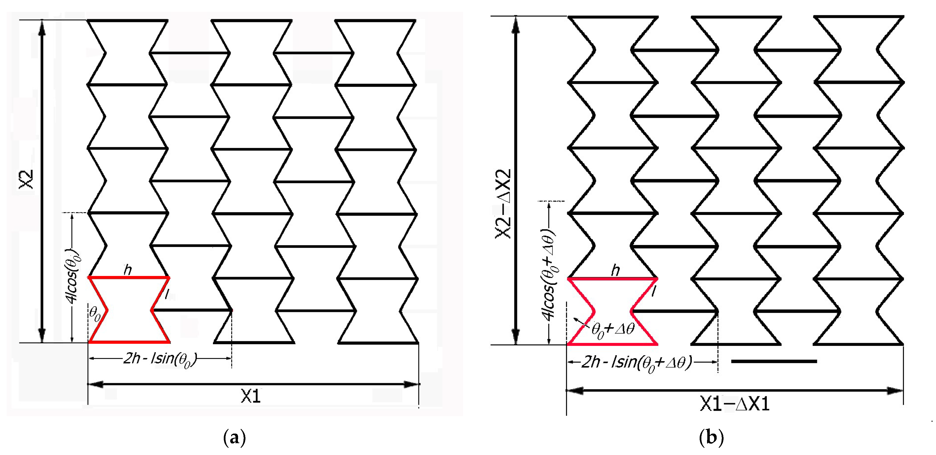
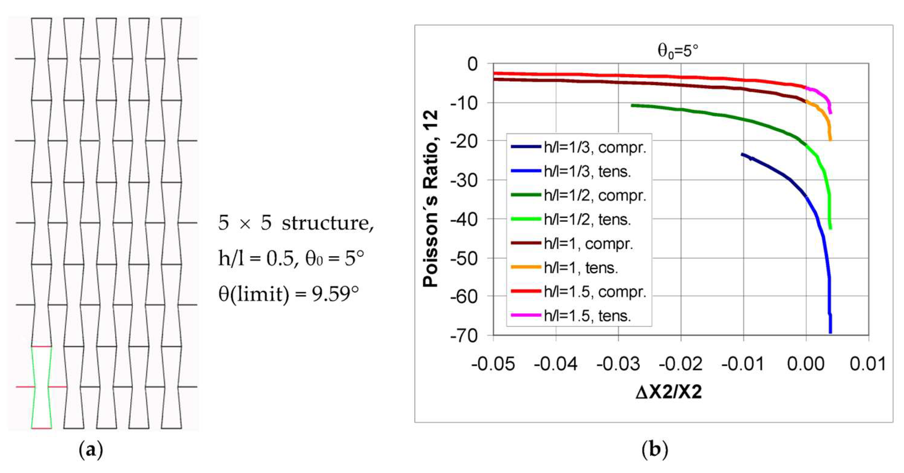
2. Geometric Analysis of an Auxetic Structure of Made of Re-Entrant (Bowtie) Unit Cells

Taking the initial angle θ0 and the angle change Δθ, similar to what has already been performed in the previous work [17], according to the diagram shown in Figure 1, the changes in the linear dimensions are as follows [55]:
Δ X 1 X 1 = sin θ 0 sin ( θ 0 ± Δ θ ) n n 1 h l sin θ 0 ,
Δ X 2 X 2 = cos ( θ 0 ± Δ θ ) cos θ 0 cos θ 0 ,
where n is the number of unit cells in the horizontal direction. For a large number of unit cells, the following is true:
Δ X 1 X 1 = sin θ 0 sin ( θ 0 ± Δ θ ) h l sin θ 0 .
Formula (3) follows on from the fact that the ratio n/(n − 1) tends toward unity, which can be practically applied for n > 7. In compression, the angle change is positive (+Δθ), while in tension, it is negative (−Δθ). This means that stretching leads to a change in the angle according to the following relationship: θ0 + Δθ → 0.
The Poisson’s ratio is given by the following relationships:
ν 12 = Δ X 1 X 1 Δ X 2 X 2 ,   ν 21 = Δ X 2 X 2 Δ X 1 X 1 .
These are general analytical formulas for describing the Poisson’s ratio for auxetic structures made of unit cells and subjected to deformation. The relationships (4) reach high NPR values if their denominator takes very small values. This means that the change in the size in one direction is very small relative to the change in the size in the orthogonal direction.
After substituting (3) into (4), a useful formula for calculating the Poisson’s ratio is obtained:
ν 12 = sin θ 0 sin ( θ 0 ± Δ θ ) h l sin θ 0 cos θ 0 cos ( θ 0 ± Δ θ ) cos θ 0 .
Calculated from Formula (5), the Poisson’s ratio is a quantity independent of the number of unit cells in the structure and depends only on its parameters, namely h/l and θ0, and on the angle change Δθ. The lack of a functional relationship between the Poisson’s ratio and the number of cells in the structure is particularly useful for many practical application designs, which usually feature a limited number of cells.
Analyzed in Formula (5), the change in angle Δθ is indicative of the movement performed by the structure under loading. In practical terms, the Poisson’s ratio requires dynamic dimensional changes. On the other hand, considering the fact that the structure is usually subjected to very small angle changes, within the limit of Δθ → 0, this theoretically means that for Δθ = 0 the structure remains locked. In that case, a limit Poisson’s ratio value can be calculated using L’Hôpital’s rule.
ν 12 ( limit ) = cos 2 ( θ 0 ) [ h l sin ( θ 0 ) ] sin ( θ 0 ) ,
This means that the Poisson’s ratio limit ν12(limit) can be approached with very small deformations of the structure. It should be added that Formula (6) is often used, although it gives errors for large deformations.
Formula (6) has the same form as that of a 2D-type structure proposed in an earlier study [14,56] and is often cited by other authors.

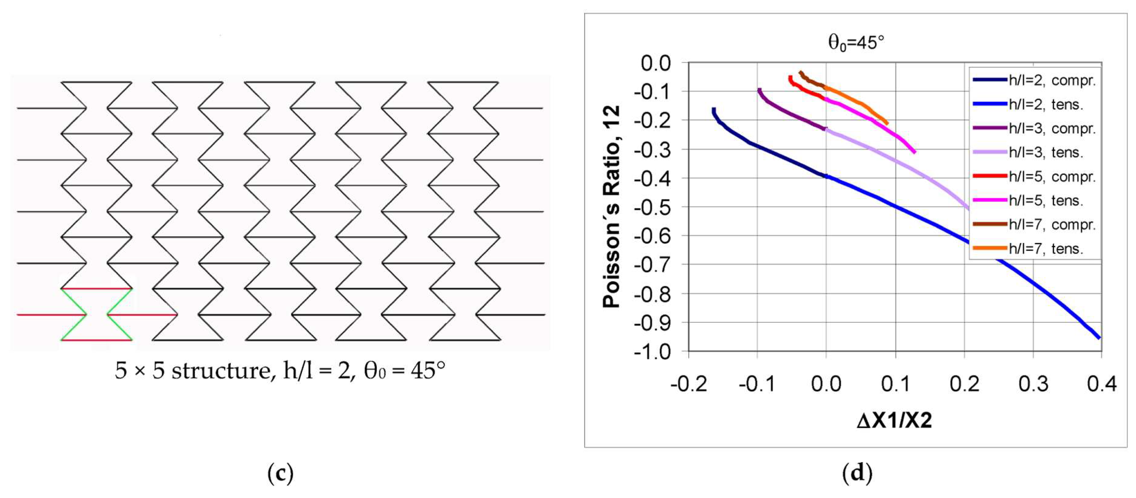
Geometric Analysis of a Structure with Dimensions of 5 × 5 (Figure 1)

The study has estimated the effects of the interaction of geometric parameters such as the strut length ratio h/l and angles θ0 and Δθ with the value of the Poisson’s ratio.
Using the formulae given above, it is possible to determine the necessary physical quantities associated with stretching and compressing a given structure. Note that these types of structures can theoretically be stretched to a maximum angle of Δθ = θ0, and be compressed by an angle of Δθ = 90° − θ(limit). Whereby θ(limit) results from the blocking of the inclined struts for the ratio of h/l < 2 and is equal to:
h 2 l = sin ( θ l i m i t ) ,
For h/l > 2 in compression, the maximum value of the angle change can be as follows: Δθ = 90° − θ0. Compressive deformation for h/l < 2 can occur up to the critical point at which the inclined struts come into contact.
Using Formula (5), the effect of the geometric parameters of h/l on the value of the Poisson’s ratio was analyzed. Two values of the initial angle θ0 were chosen, and both the processes of compression (Δθ > 0) and tension (Δθ < 0) were taken into account.
The presented relationships indicate that the Poisson’s ratio of the auxetic re-entrant structure strongly depends on the level of strain expressed by Δθ. These relationships show a monotonic trend with respect to the changes in angle Δθ. It can be seen that at large strains, the value of the Poisson’s ratio is not constant and changes markedly throughout the range of deformation. However, its change is monotonic—without any extremes. The negative value of the Poisson’s ratio decreases significantly with large compressive deformation and increases strongly in tension.
It can also be seen (Figure 2) that the geometric parameter of the concave cell, i.e., h/l, has a very significant effect on the magnitude of the Poisson’s ratio, and for more elongated cells, its negative value increases. From the relationships shown in Figure 2, it can be seen that the analyzed structure achieves a limit value of the Poisson’s ratio νlimit according to Formula (6). The highest NPR values are obtained for tension, while for compression, the NPR decreases from the limit value toward zero. In addition, it becomes clear that the more extended the re-entrant unit cells are, the higher the NPR values that can be obtained. Also, there is a strong effect of the θ0 angle on the NPR. As the angle θ0 increases, the NPR values decrease. It can be thus concluded that when stretching the structure shown in Figure 1, the value of the NPR increases—i.e., the Poisson’s ratio ν12 becomes more negative and, conversely, when compressing the structure, the value of the NPR becomes smaller.
The relative changes in the dimensions ΔX1/X1 of the structure in the horizontal direction, in the considered range of the angle change Δθ are similar for both compression and tension, and for θ0 = 10°, they do not theoretically exceed about 40%. However, for θ0 = 45°, there is a fundamentally big difference between tension and compression. In tension, one can expect a much larger change in the linear dimensions than in compression (Figure 3b).
If one relates the presented theoretical relationships to practical conditions, one should consider small ranges of linear dimensional changes—usually less than 0.1, which are due to the limited elastic properties of the material of the re-entrant unit cells.
Figure 4 compares the relationship between the Poisson’s ratio and the relative elongation (+) or relative contraction (−) for this range and in three structures (h/l = 1.5, 2, and 2.5, respectively). This comparison shows that lower angle values θ0 lead to a higher NPR. On the other hand, flattening the re-entrant unit cells (higher h/l ratio) results in lower NPR values.
The presented relationships indicate a definite trend in the functional relationship between the Poisson’s ratio and the h/l parameter, which is also evident for the theoretical value of Δθ = 0. For instance, for a structure with an initial angle θ0 = 45° and h/l = 1.5 (Figure 4b), one obtains a limit value of the Poisson’s ratio (for Δθ = 0° and ΔX/X = 0) equal to ν12 = −0.605. In this case, due to the limited possibility of changing the angle in compression, a maximum change in the linear dimensions in the horizontal direction of only ΔX1/X1 = 0.063 can be achieved. Additional practical information that can be derived from the diagrams of Figure 4 is that for the mentioned structure in tension, NPR values higher than −0.605 are obtained, with the reverse being true in compression. In general, one can reiterate that the Poisson’s ratio for auxetic re-entrant structures reaches a constant value at very small deformations.
Another interesting issue is the choice of the shape of the re-entrant unit cells, since their width determines the value of the NPR. Analyzing the structures with the parameter h/l > 2 and with the initial angle θ0 = 45° one can obtain full ranges (Δθ = 45°), which are the same for both compression as well as tension. A detailed interpretation of the relationships considered yields the following conclusions.
Firstly, the NPR values decrease with an increasing parameter of h/l—Figure 5a, whereas compressing the structure gives smaller changes in the linear dimensions in the horizontal direction than in the vertical direction—Figure 5b. Regardless of the h/l value, tension leads to a constant value of dimensional change—Figure 5b, and to smaller NPR values than compression—Figure 5a. On the other hand, large changes in the dimensions in the horizontal direction (ΔX1/X1) accompanying tension correspond to higher NPR values than those accompanying compression—Figure 5d.
The diagram of the structure shown in Figure 5c can help one to visualize the stretching process to better attest to the above observations. If the analyzed structures are made of wide re-entrant unit cells (h/l ≥ 2) and with an inclined angle θ0 = 45°, relatively small NPR values can be obtained—Figure 5d. However, for tension, NPR values are higher than those for compression. It can be noted that the presented relationships show a monotonic trend of the Poisson’s ratio, both as a function of the opening angle Δθ and of the parameter h/l—Figure 5a. Also, there is a monotonic curvilinear relationship between the change in the linear dimensions in the horizontal direction (X1) and in the vertical direction (X2)—Figure 5b. It should be noted that for such structures, the dimensional change in the vertical direction can theoretically reach 100%, while the maximum change in the horizontal direction can reach about 41%.
On the other hand, for structures formed from narrow re-entrant unit cells, i.e., for h/l < 2, very high NPR values can be obtained. In this case, however, it is not possible to obtain greater Δθ angle changes than those from Formula (7).
The presented relationships for structures made of narrow re-entrant unit cells (Figure 6a) yield large NPR values—Figure 6b. For example, for a structure made of re-entrant unit cells with the parameters, h/l = 0.5 and θ0 = 5°, theoretically for the angle change Δθ = −5°, a Poisson’s ratio of −42.4 is obtained in tension, whereas in compression to an angle Δθ = +4.5°, the Poisson’s ratio is −10.8. It should be noted that the maximum relative elongation in the horizontal direction is much greater than the relative elongation in the vertical direction and, in this case, it is equal to ΔX1/X1 = 0.16 for tension, and ΔX1/X1 = −0.3 for compression.
In general, as the h/l parameter decreases, higher NPR values are obtained, with a strong decrease in the elongation values. Taking the Poisson’s ratio ν12, it reaches large negative values with very little relative change in the linear dimensions in the vertical direction (Figure 6b)—which stems from θ(limit). While in this case, the NPR values for the parameter h/l > 1 do not undergo large changes, they increase strongly for longer unit cells h/l < 1—Figure 6b.
The presented geometric analysis of the structure made of re-entrant unit cells shows that such structures exhibit monotonic relationships of the Poisson’s ratio, both as a function of the angle change Δθ, and as a function of the dimensional change ΔX/X, and that the Poisson’s ratio takes negative values. Structures made of re-entrant unit cells thus have auxetic properties, i.e., the NPR effect emerges. To verify these findings, numerous physical models have been assembled. The following section presents selected models of auxetic structures made of metallic materials.
Two types of re-entrant auxetic structures are presented below, with the first type in the form of a spatial model, which is more favorable for the realization of the compression process (free of buckling), while the second type is a flat model chosen for the realization of the tension process.

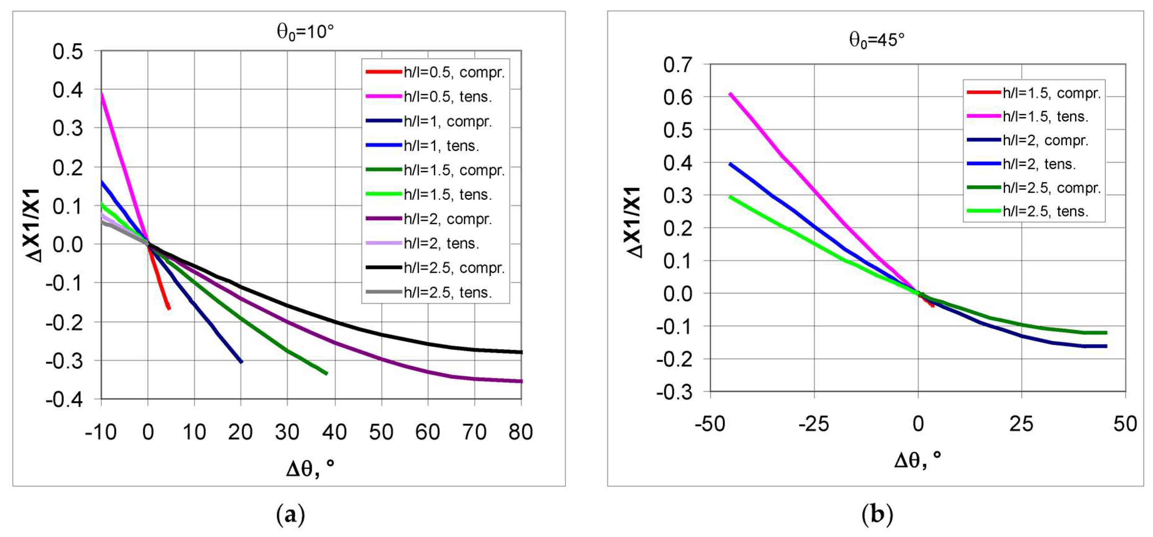
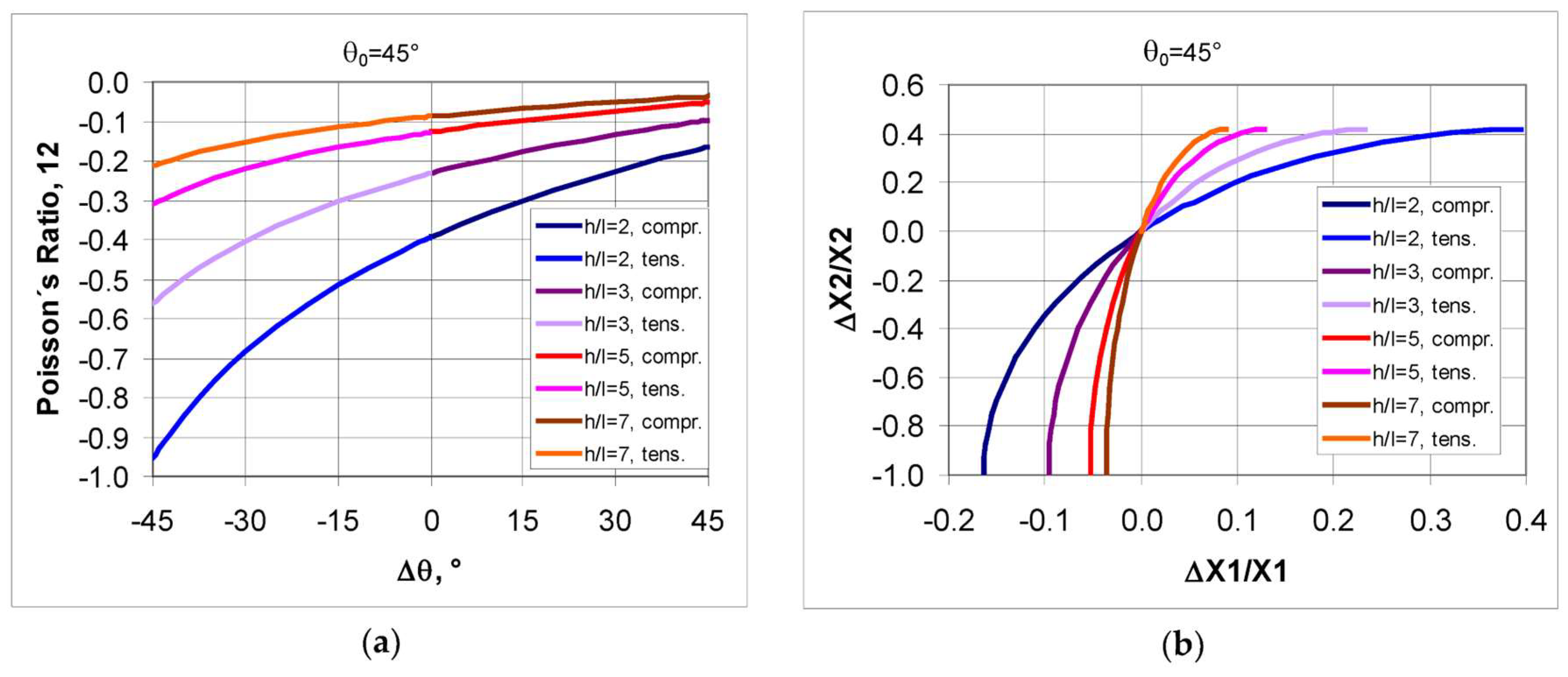
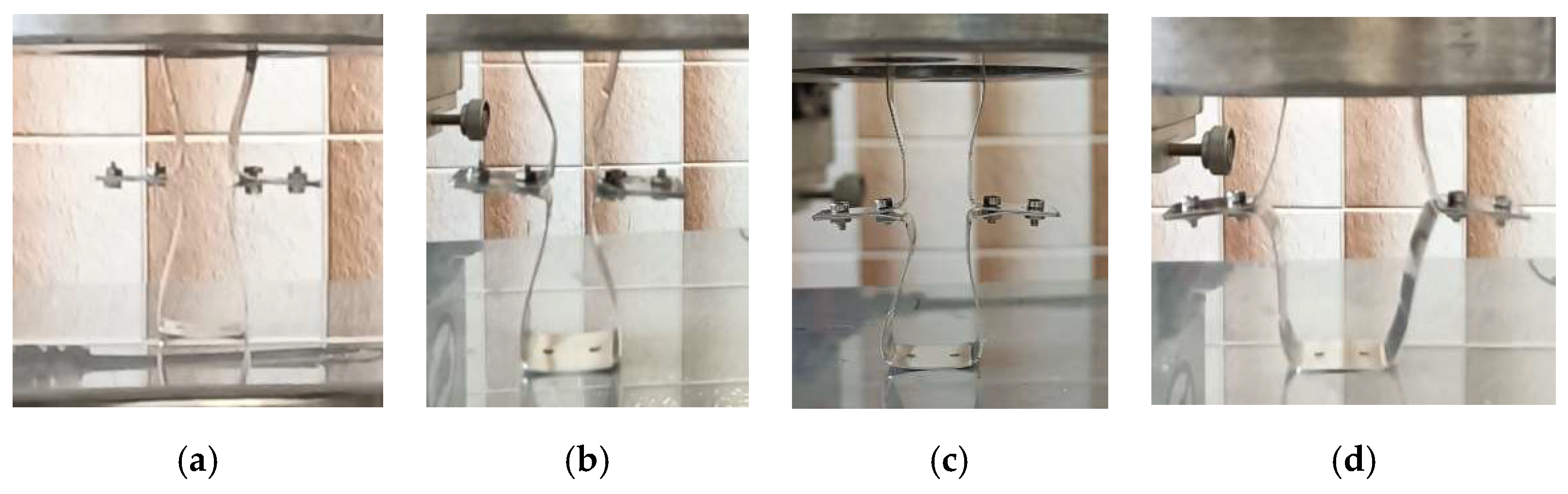
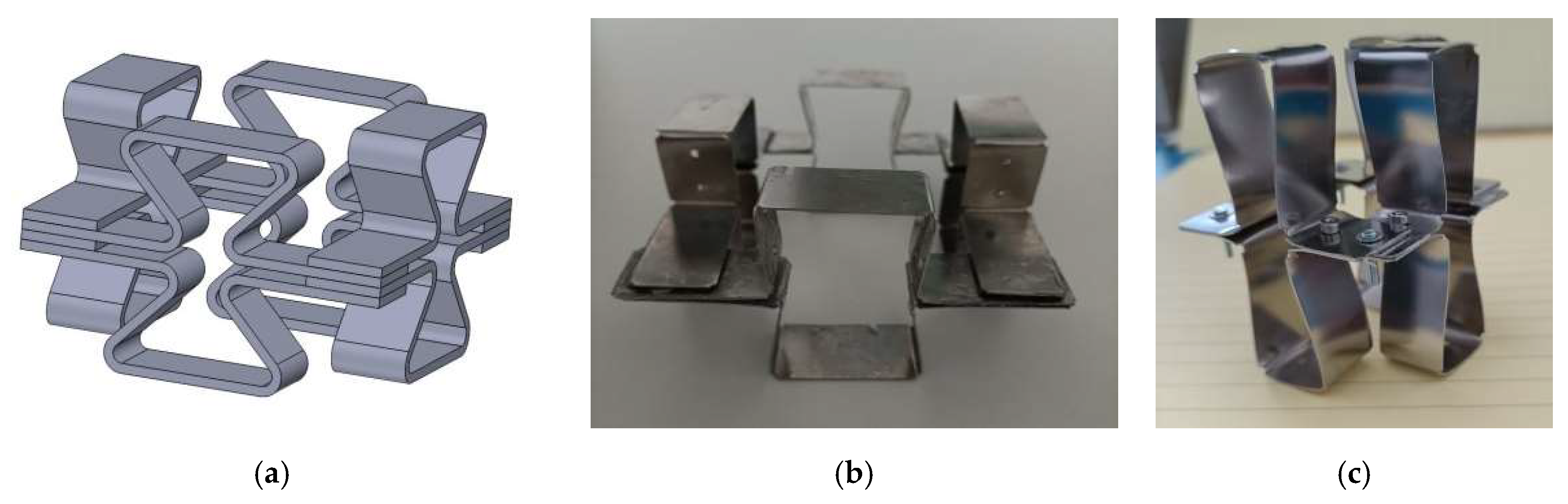
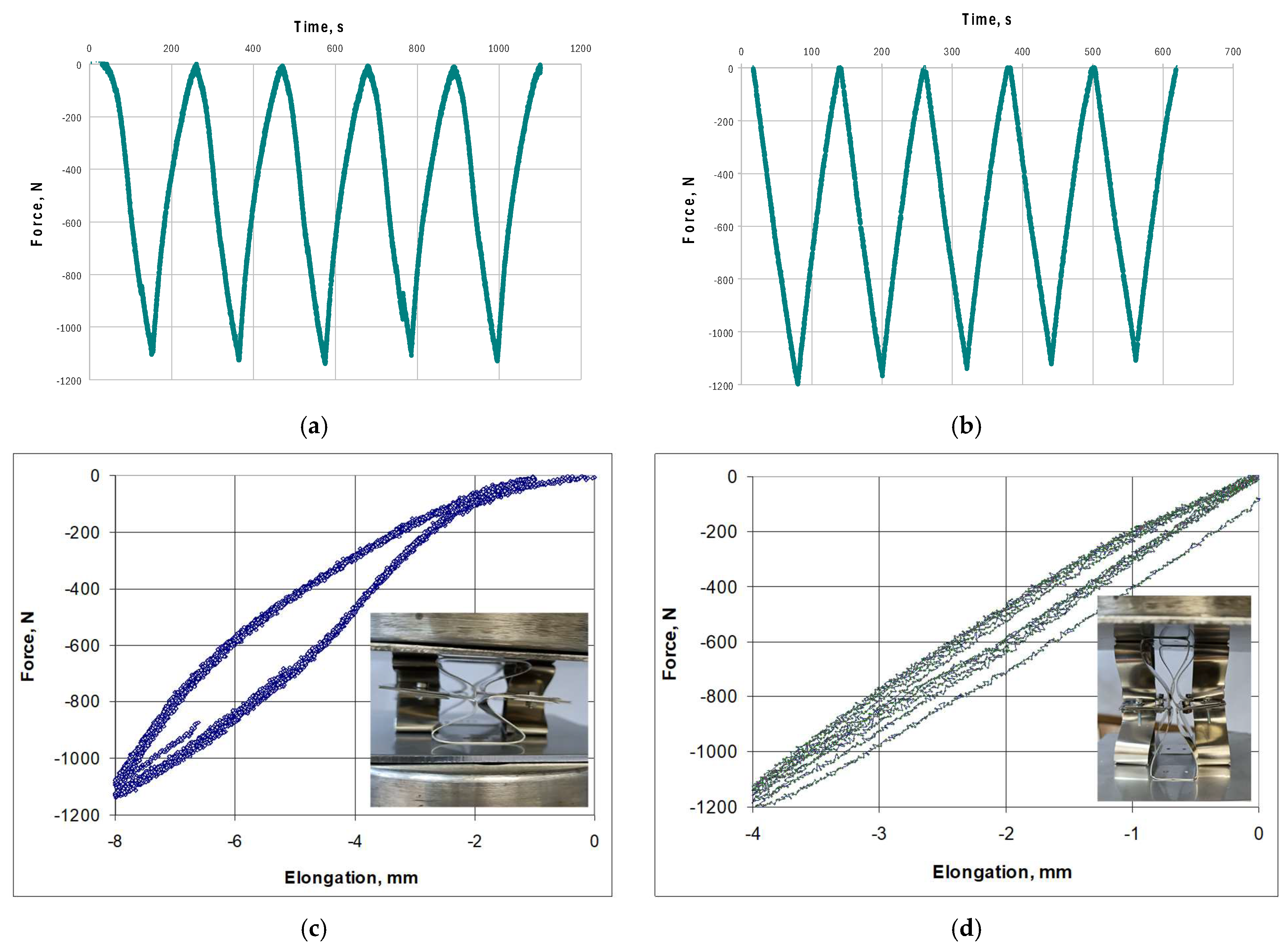
3. Models of Auxetic Structures

First, the behavior of individual re-entrant unit cells was studied (Figure 7a). Re-entrant-type unit cells made of elastic steel sheet were subjected to compression tests.
The spatial structures were prepared from strips of a Rostfreier Federbandstahl 1.4310 steel sheet, 0.45 mm thick (h + s Präzisions-Folien GmbH, Vohenstrauß, Germany). The strips and the holes in them were produced using a laser, with the sheet strips bent and connected with M1.5 screws to obtain the re-entrant cells. The holes for the connecting screws were 1.6 mm in diameter. The manual fabrication of the structures allowed us to obtain models that are only a practical illustration, and for detailed mechanical studies, a more expert approach is needed for the construction of the structures.
The observed dimensional changes are illustrated in the photographs below. It was demonstrated that a single re-entrant unit cell (h/l = 1.5, θ0 = 15°) subjected to compression can exhibit auxetic behavior as well as bulge.
The deformation of the re-entrant steel sheet unit cell shown in Figure 7b consisted of changing its dimensions in the vertical direction by 8 mm (Figure 7c) and by 12 mm (Figure 7d). The observed non-uniform deformation was due to small differences in the unit cell symmetry.
Similar behavior was observed for narrow unit cells (h/l = 2/3, θ0 = 15°) for which the geometric limit is θlimit = 19.3° (Figure 8).
In this case, the deformation occurred in two ways. Changing the height of the unit cell by 8 mm resulted in either auxetic behavior—Figure 8a,b, or non-auxetic behavior—Figure 8c,d. The difference was caused by the deformation of the short horizontal strut. Its contact surface changed from straight to the shape of an outstretched letter “w” (Figure 8d). It was found that the “w”-shape-forming effect of the horizontal strut can also occur in compression in wider cells, especially when pressure is applied at a particular point or when the bottom of the cell contacting the lower plate of the testing machine leads to this effect.
While a single steel sheet cell does not undergo lateral buckling under compression, planar structures of such cells are easily subjected to it. By combining the four re-entrant unit cells (Figure 9a), a volumetric structure was obtained, which was more appropriate for the squeezing process. A structure of this type is very sensitive to possible inaccuracies in the dimensions and requires very careful manufacturing, especially regarding the horizontal struts being in perfect contact with each other. The structures were made of steel sheets (15 mm wide, 0.25 mm thick) joined to form a volumetric structure, with cell parameters of h/l = 1.433, θ0 = 30° (Figure 9b) and h/l = 0.5, as well as θ0 = 5° (Figure 9c).
During the performed measurement, it was found that the compression of the structure from the initial state to state X (locking of the inclined struts, i.e., the ‘contact point’) corresponding to an angle of 41° occurs within the elastic range, which was connected to the cyclic compression and release.
In this case, one can speak of a springback of the structure, which returns to its original shape when the pressure is released. From the force vs. elongation curves shown below, it is clear that springback changes at different angle values and at different lengths of the inclined cell.
A larger angle θ0 results in greater springback (Figure 10a), which is expressed by a wider hysteresis loop. Its width is proportional to the elastic energy stored in the structure when compressed.
The cyclic compression process followed a characteristic pattern for both the tested structures. The presented curves for the changes in force over time for the compression process (Figure 10a,b) reflect the differences in the geometry of the structures. One can see a more curvilinear course for a structure with parameters h/l = 1.433, θ0 = 30° (shorter structure) and smaller values of the force required to squeeze this structure to the X position compared with a longer structure (with parameters h/l = 0.5, θ0 = 5°). For the longer structure, there was a tendency to continuously decrease the maximum value of the force needed to achieve the given amount of compression (Figure 10b).
A comparison of the experimental relationships in Figure 10c,d shows that the angle θ0 and the length of the inclined strut l affect the amount of stress and strain. This was also reflected in the width of the obtained hysteresis loop, which was narrower the greater the length of the inclined strut. In the structure with such elongated unit cells (Figure 10d), there was an observed bending of the inclined strut, which meant that a slightly higher force was required to compress this structure. It can also be taken into account that the width of the hysteresis loop was also affected by the fatigue of the material and slight plastic deformation of the structures because after the tests had been completed, a slight shortening of the structures was observed, from 40 mm to 36 mm (Figure 10a) and from 66 mm to 62 mm (Figure 10b).
In position X, for a structure with parameters h/l = 1.433 and θ0 = 30°, the Poisson’s ratio value was estimated to be about −1, and for a structure with parameters h/l = 0.5 and θ0 = 5°, the Poisson’s ratio value was as high as approximately −12. Nevertheless, the force vs. elongation curves obtained from the compression tests testify to the repeatability of the compression and release process, which is characteristic of the elastic range. It has also been found that, in the elastic range, all four connected unit cells were evenly deformed.
In tensile tests, on the other hand, a flexible 4 × 4 structure made of double torsion springs was used (Figure 11). This idea allows for large flexible deformations of metal structures by bending the strut joints more easily. In the initial state, the dimensions of the structure were X1 = 265 mm, X2 = 208 mm, for h = 40 mm, l = 30, θ0 = 30°.
The components from which the re-entrant cells are made include torsion springs made from 0.8 gauge DH steel wire (Reiner Schmid Produktions GmbH, Solingen, Germany). These concepts arise from the bending mechanism, which is involved in the deformation of the re-entrant structures. Torsion springs exhibit a natural bending mechanism and elastically retain mechanical energy when bent.
Tensile tests were conducted for the given values of maximum elongation in the vertical direction (Figure 12).
The tensile curves of the structures in the elastic range shown in Figure 12 illustrate successive attempts to increase the amplitude of the tension and release cycle from 4 mm to 12 mm. The tension and release cycle was repeated five times. It can be assumed that the tensile force vs. elongation curves for a given structure coincide. Much less force was needed for stretching a structure made of two unit cells than for stretching a 4 × 4 structure. The slight hysteresis observed may be due to the friction occurring in the torsion springs. It was found that for the range of stretching of the structures, the Poisson’s ratio varies slightly from about −1.4 to −1.7.

4. Conclusions

The presented examples of metallic mechanical metamaterials using re-entrant unit cells address a wide range of elastic properties. Through cyclical loading and release, the elastic properties lead to energy accumulation. The occurring changes in the linear dimensions of the structures lead to negative Poisson’s ratio values.
The geometric analysis performed showed the role of the h/l parameter in the obtained Poisson’s ratio. Large NPR values are possible for low values of h/l, although the initial angle of the structure θ0 and the degree of opening of the structure expressed by the change in angle Δθ are also relevant here. At the same time, it should be remembered that the re-entrant structures can undergo non-damaging deformation only for certain changes in angle Δθ, namely, in tension from the initial angle θ0 to 0°, and in compression from the initial angle θ0 to θlimit (for h/l < 2) and up to 90° (for h/l > 2). For structures made of unit cells with h/l < 2, there is a limit angle value θlimit. This angle limit θlimit also cannot be exceeded in the implementation of structures if h/l < 2. The value of this angle is θ(limit) = arcsin(h/2l) [55]. This entails that the initial angle θ0 affects the strut length [57].
Both the parameter h/l and the initial angle θ0 affect the values of the obtained dimensional changes in tension and compression; for example, for θ0 = 10°, large elongation is obtained for h/l = 0.5 and large compression for h/l = 2.5. On the other hand, high NPR values are possible for structures made of longer unit cells, i.e., for h/l < 1. It is also clear that the re-entrant cell structures exhibit auxetic behavior, i.e., the NPR.
In the produced models, thanks to the solutions applied, there was a reduction in the stress concentration at the strut joints. Both curved connections for structures in compression tests and spring connections for structures in tensile tests have performed well in this regard. A method of assembling structures has been successfully tested, which also has the potential for mass and automated production.
The assembled structures subjected to compression tests, especially those of longer unit cells (Figure 9b), showed little bending of the inclined struts, which, at a larger scale of this phenomenon, can diminish the auxetic effect [58].
Both the structures under compression and those under tension exhibited hysteresis loops of elastic strain energy, with the structures showing little change in linear dimensions after cyclic loading. This may indicate the presence of a small proportion of irreversible deformation. It has been confirmed that the cycle of loading and relaxation can be repeated multiple times, which is known as the low-cycle compression test [59].
The presented experimental models of structures, illustrating the phenomenon of auxetic behavior, should be regarded as an easy-to-implement proposal, with the imperfections occurring causing the noted deviations in the experimental curves (Figure 10 and Figure 12). In further studies, we intend to provide a better instrumentation for making elementary cells, as well as for combining them and assembling model structures.
In summary, the auxetic structures studied could potentially be used as “shock absorbers” for dissipating mechanical energy. In particular, the new concept of unit cells in which the struts are connected with springs can be used to develop new and reconfigurable structures with auxetic properties.

Author Contributions

Conceptualization: J.P.; Methodology: J.P.; Software: G.J. and J.P.; Validation: J.P. and G.J.; Formal Analysis: J.P.; Investigation: J.P. and G.J.; Resources: J.P.; Data Curation: J.P.; Writing—Original Draft Preparation: J.P.; Writing—Review & Editing: J.P. and M.P.; Visualization: M.P.; Supervision: J.P. and M.P.; Project Administration: M.P.; Funding Acquisition: J.P. All authors have read and agreed to the published version of the manuscript.

Funding

The research activities were co-financed by the funds granted under the Research Excellence Initiative of the University of Silesia in Katowice.

Data Availability Statement

The original contributions presented in the study are included in the article, further inquiries can be directed to the corresponding author.

Conflicts of Interest

The authors declare that they have no known conflicting social interests or personal connections that may have arisen and influenced the work reported in this paper. The study is part of a strategic area of interest covering the analysis and assembly of auxetic systems.

References

  1. Callister, W.D., Jr. Materials Science and Engineering. An Introduction, 7th ed.; John Wiley and Sons Inc.: Hoboken, NJ, USA, 2007. [Google Scholar]
  2. Ziolkowski, R.W. Metamaterials: The early years in the USA. EPJ Appl. Metamater. 2014, 1, 5. [Google Scholar] [CrossRef]
  3. Pendry, J.; Zhou, J.; Sun, J. Metamaterials: From Engineered Materials to Engineering Materials. Engineering 2022, 17, 1–2. [Google Scholar] [CrossRef]
  4. Boardman, A. Pioneers in metamaterials: John Pendry and Victor Veselago. J. Opt. 2011, 13, 020401. [Google Scholar] [CrossRef]
  5. Yu, X.; Zhou, J.; Liang, H.; Jiang, Z.; Wu, L. Mechanical metamaterials associated with stiffness, rigidity and compressibility: A brief review. Prog. Mater. Sci. 2018, 94, 114–173. [Google Scholar] [CrossRef]
  6. Sun, J.; Liu, X.; Zhou, J.; Kudyshev, Z.; Litchinitser, N.M. All-Dielectric Transition Magnetic Metamaterials. Sci. Rep. 2015, 5, 16154. [Google Scholar] [CrossRef]
  7. Sklan, S.R.; Li, B. Thermal metamaterials: Functions and prospects. Natl. Sci. Rev. 2018, 5, 138–141. [Google Scholar] [CrossRef]
  8. Available online: http://people.ee.duke.edu/~drsmith/metamaterials/metamaterials_homogenization.htm (accessed on 20 August 2024).
  9. Smith, D.R.; Pendry, J.B. Homogenization of metamaterials by field averaging. J. Opt. Soc. Am. B 2006, 23, 321. [Google Scholar] [CrossRef]
  10. Elipe, A.C.; Lantada, A.D. Comparative study of auxetic geometries by means of computer-aided design and Engineering. Smart Mater. Struct. 2012, 21, 105004. [Google Scholar] [CrossRef]
  11. Grima, J.N.; Evans, K.E. Auxetic behavior from rotating squares. J. Mater. Sci. Lett. 2000, 19, 1563–1565. [Google Scholar] [CrossRef]
  12. Almgren, R.F. An isotropic three-dimensional structure with Poisson’s ratio = −1. J. Elast. 1985, 15, 427–430. [Google Scholar] [CrossRef]
  13. Masters, I.G.; Evans, K.E. Models for the elastic deformation of honeycombs. Compos. Struct. 1996, 35, 403–422. [Google Scholar] [CrossRef]
  14. Gibson, L.; Ashby, M. Cellular Solids: Structure and Properties, 2nd ed.; Cambridge University Press: Cambridge, UK, 1999. [Google Scholar]
  15. Tarlochan, F. Sandwich Structures for Energy Absorption Applications: A Review. Materials 2021, 14, 4731. [Google Scholar] [CrossRef] [PubMed]
  16. Francisco, M.B.; Pereira, J.L.J.; Oliver, G.A.; da Silva, L.R.R.; Cunha, S.S., Jr.; Gomes, G.F. A review on the energy absorption response and structural applications of auxetic structures. Mech. Adv. Mater. Struct. 2022, 29, 5823–5842. [Google Scholar] [CrossRef]
  17. Hu, L.L.; Zhou, M.Z.; Deng, H. Dynamic crushing response of auxetic honeycombs under large deformation: Theoretical analysis and numerical simulation. Thin-Walled Struct. 2018, 131, 373–384. [Google Scholar] [CrossRef]
  18. Han, D.; Ren, X.; Zhang, Y.; Zhang, X.Y.; Zhang, X.G.; Luo, C.; Xie, Y.M. Lightweight auxetic metamaterials: Design and characteristic study. Compos. Struct. 2022, 293, 115706. [Google Scholar] [CrossRef]
  19. Han, D.; Zhang, Y.; Zhang, X.Y.; Xie, Y.M.; Ren, X. Lightweight auxetic tubular metamaterials: Design and mechanical characteristics. Comp. Struct. 2023, 311, 116849. [Google Scholar] [CrossRef]
  20. Shirzad, M.; Zolfagharian, A.; Bodaghi, M.; Nam, S.Y. Auxetic metamaterials for bone-implanted medical devices: Recent advances and new perspectives. Eur. J. Mech.-A Solids 2023, 98, 104905. [Google Scholar] [CrossRef]
  21. Fardan, M.F.; Lenggana, B.W.; Ubaidillah, U.; Choi, S.-B.; Susilo, D.D.; Khan, S.Z. Revolutionizing Prosthetic Design with Auxetic Metamaterials and Structures: A Review of Mechanical Properties and Limitations. Micromachines 2023, 14, 165. [Google Scholar] [CrossRef]
  22. Yang, C.; Vora, H.D.; Chang, Y. Behavior of auxetic structures under compression and impact forces. Smart Mater. Struct. 2018, 27, 025012. [Google Scholar] [CrossRef]
  23. Curtis, S.M.; Dengiz, D.; Bumke, L.; Quandt, E. Shape Memory Alloy Thin Film Auxetic Structures. In Proceedings of the International Conference on Shape Memory and Superelastic Technologies, SMST 2022, Carlsbad, CA, USA, 16–20 May 2022; ASM International: San Diego, CA, USA, 2022; pp. 11–13. [Google Scholar]
  24. Isaac, C.W.; Duddeck, F. Recent progress in 4D printed energy-absorbing metamaterials and structures. Virtual Phys. Prototyp. 2023, 18, e2197436. [Google Scholar] [CrossRef]
  25. Naboni, R.; Mirante, L. Metamaterial computation and fabrication of auxetic patterns for Architecture. Digit. Manuf. Rapid Prototyp. 2015, 2, 129–136. [Google Scholar] [CrossRef]
  26. Jiang, W.; Ren, X.; Wang, S.L.; Zhang, X.G.; Zhang, X.Y.; Luo, C.; Xie, Y.M.; Scarpa, F.; Alderson, A.; Evans, K.E. Manufacturing, characteristics and applications of auxetic foams: A state-of-the-art review. Compos. Part B 2022, 235, 109733. [Google Scholar] [CrossRef]
  27. Li, X.; Peng, W.; Wu, W.; Xiong, J.; Lu, Y. Auxetic mechanical metamaterials: From soft to stiff. Int. J. Extrem. Manuf. 2023, 5, 042003. [Google Scholar] [CrossRef]
  28. Balan, M.; Mertens, J.; Bahubalendruni, M.R. Auxetic mechanical metamaterials and their futuristic developments: A state-of-art review. Mater. Today 2023, 34, 105285. [Google Scholar] [CrossRef]
  29. Yin, H.; Xiao, Y.; Wen, G.; Qing, Q.; Deng, Y. Multiobjective optimization for foam-filled multi-cell thin-walled structures under lateral impact. Thin-Walled Struct. 2015, 94, 1–12. [Google Scholar] [CrossRef]
  30. Necemer, B.; Klemenc, J.; Glodež, S. The computational LCF-analyses of chiral and Re-entrant auxetic structure using the direct cyclic algorithm. Mater. Sci. Eng. A 2020, 789, 139618. [Google Scholar] [CrossRef]
  31. Ghiasvand, A.; Khanigi, A.F.; Guerrero, J.W.G.; Derazkola, H.A.; Tomków, J.; Janeczek, A.; Wolski, A. Investigating the Effects of Geometrical Parameters of Re-Entrant Cells of Aluminum 7075-T651 Auxetic Structures on Fatigue Life. Coatings 2023, 13, 405. [Google Scholar] [CrossRef]
  32. Dong, Z.; Li, Y.; Zhao, T.; Wu, W.; Xiao, D.; Liang, J. Experimental and numerical studies on the compressive mechanical properties of the metallic auxetic reentrant honeycomb. Mater. Des. 2019, 182, 108036. [Google Scholar] [CrossRef]
  33. Zhang, J.; Lu, G.; Wang, Z.; Ruan Alomarah, D.A.; Durandet, Y. Large Deformation of an Auxetic Structure in Tension: Experiments and Finite Element Analysis. Compos. Struct. 2017, 184, 92–101. [Google Scholar] [CrossRef]
  34. Sangsefidi, A.R.; Dibajian, S.H.; Kadkhodapour, J.; Anaraki, A.P.; Schmauder, S.; Schneider, Y. An Abaqus plugin for evaluation of the Auxetic structure performance. Eng. Comput. 2022, 38 (Suppl. S2), S1681–S1704. [Google Scholar] [CrossRef]
  35. Xiao, D. Insight into the negative Poisson’s ratio effect of metallic auxetic reentrant honeycomb under dynamic compression. Mater. Sci. Eng. A 2019, 763, 138151. [Google Scholar] [CrossRef]
  36. Francesconi, L.; Baldi, A.; Dominguez, G.; Taylor, M.L. An Investigation of the Enhanced Fatigue Performance of Low-porosity Auxetic Metamaterials. Exp. Mech. 2020, 60, 6093–6107. [Google Scholar] [CrossRef]
  37. Amin, F.; Najabat Ali, M.; Ansari, U.; Mir, M.; Minhas, M.A.; Shahid, W. Auxetic Coronary Stent Endoprosthesis: Fabrication and Structural Analysis. J Appl. Biomater. Funct. Mater. 2015, 13, e127–e135. [Google Scholar] [CrossRef]
  38. Zhou, Y.; Zhou, C.; Shu, Z.; Jia, L.-J. Effect of Two-Dimensional Re-Entrant Honeycomb Configuration on Elastoplastic Performance of Perforated Steel Plate. Appl. Sci. 2020, 10, 3067. [Google Scholar] [CrossRef]
  39. Nedoushan, R.J. Improvement of energy absorption of expanded metal tubular structures under compressive loads. Thin-Walled Struct. 2020, 157, 107058. [Google Scholar] [CrossRef]
  40. Arifurrahman, F.; Critchley, R.; Horsfallm, I. Experimental numerical study of auxetic sandwich panels on 160 g of PE4 blast loading. J. Sandw. Struct. Mater. 2021, 23, 3902–3931. [Google Scholar] [CrossRef]
  41. Box, F.; Johnson, C.G.; Pihler-Puzović, D. Hard auxetic metamaterials. Extrem. Mech. Lett. 2020, 40, 100980. [Google Scholar] [CrossRef]
  42. Dallago, M.; Raghavendra, S.; Luchin, V.; Zappini, G.; Pasini, D.; Benedetti, M. Geometric assessment of lattice materials built via selective Laser Melting. Mater. Today Proc. 2019, 7, 7353–7361. [Google Scholar] [CrossRef]
  43. Kranz, J.; Herzog, D.; Emmelmann, C. Design guidelines for laser additive manufacturing of lightweight structures in TiAl6V4. J. Laser Appl. 2015, 27, S14001. [Google Scholar] [CrossRef]
  44. Bourell, D.; Kruth, J.P.; Leu, M.; Levy, G.; Rosen, D.; Beese, A.M.; Clare, A. Materials for additive manufacturing. CIRP Ann. Manuf. Technol. 2017, 66, 659–681. [Google Scholar] [CrossRef]
  45. Yánez, A.; Cuadrado, A.; Martel, O.; Afonso, H.; Monopoli, D. Gyroid porous titanium structures: A versatile solution to be used as scaffolds in bone defect reconstruction. Mater. Des. 2018, 140, 21–29. [Google Scholar] [CrossRef]
  46. Yang, L.; Harrysson, O.; West, H.; Cormier, D. Compressive properties of Ti–6Al–4V auxetic mesh structures made by electron beam melting. Acta Mater. 2012, 60, 3370–3379. [Google Scholar] [CrossRef]
  47. Brown, T.D.; Dalton, P.D.; Hutmacher, D.W. Melt electrospinning today: An opportune time for an emerging polymer process. Prog. Polym. Sci. 2016, 56, 116–166. [Google Scholar] [CrossRef]
  48. Hassanin, H.; Abena, A.; Elsayed, M.A.; Essa, K. 4D printing of NiTi auxetic structure with improved ballistic performance. Micromachines 2020, 11, 745. [Google Scholar] [CrossRef] [PubMed]
  49. Shivdeo, A.; Hardikar, A.; Bhikule, R.; Wagholikar, S.; Borhade, O.; Walame, M.V. Analysis of 2D Auxetic Metamaterial as a Variable Macro and Micro Structural Filter. Int. Res. J. Eng. Technol. 2019, 6, 695–700. [Google Scholar]
  50. Ghaedizadeh, A.; Shen, J.; Ren, X.; Xie, Y.M.M. Tuning the Performance of Metallic Auxetic Metamaterials by Using Buckling and Plasticity. Materials 2016, 9, 54. [Google Scholar] [CrossRef]
  51. Dengiz, D.; Goldbeck, H.; Curtis, S.M.; Bumke, L.; Jetter, J.; Quandt, E. Shape Memory Alloy Thin Film Auxetic Structures. Adv. Mater. Technol. 2023, 8, 2201991. [Google Scholar] [CrossRef]
  52. He, G.; Tan, Q.; Jiang, G.; Li, Q. A novel mechanism for auxetic behavior in entangled materials with a spiral wire structure. Smart Mater. Struct. 2014, 23, 095011. [Google Scholar] [CrossRef]
  53. Joseph, A.; Mahesh, V.; Harursampath, D. On the application of additive manufacturing methods for auxetic structures: A review. Adv. Manuf. 2021, 9, 342–368. [Google Scholar] [CrossRef]
  54. Friis, E.A.; Lakes, R.S.; Park, J.B. Negative Poisson’s ratio polymeric and metallic foams. J. Mater. Sci. 1988, 23, 4406–4414. [Google Scholar] [CrossRef]
  55. Plewa, J.; Płońska, M.; Junak, G. Experimental study of auxetic structures made of reentrant cells (“bow” type). Materials 2024, 17, 3061. [Google Scholar] [CrossRef] [PubMed]
  56. Smith, C.W.; Grima, J.N.; Evans, K.E. A novel mechanism for generating auxetic behaviour in reticulated foams: Missing rib foam model. Acta Mater. 2000, 48, 4349–4356. [Google Scholar] [CrossRef]
  57. Levy, O.; Goldfarb, I. Design considerations for negative Poisson ratio structures under large deflection for MEMS applications. Smart Mater. Struct. 2006, 15, 1459–1466. [Google Scholar] [CrossRef]
  58. Lekesiz, H.; Bhullar, S.K.; Karaca, A.A.; Jun, M.B.G. Mechanical characterization of auxetic stainless steel thin sheets with reentrant Structure. Smart Mater. Struct. 2017, 26, 085022. [Google Scholar] [CrossRef]
  59. Lvov, V.A.; Senatov, F.S.; Korsunsky, A.M.; Salimon, A.I. Design and Mechanical Properties of 3D-Printed Auxetic Honeycomb Structure. Mater. Today Comm. 2020, 24, 1011173. [Google Scholar] [CrossRef]
Figure 1. Auxetic structure 5 × 5 made of re-entrant cells (bowties) in the initial state (a), and after compression (b).
Metals 14 01272 g001
Figure 2. Changes in the Poisson’s ratio as a function of the angle change Δθ for θ0 = 10° (a) and θ0 = 45° (b) for a 5 × 5 structure with parameters h/l = 0.5, 1, 1.5, 2, and 2.5.
Metals 14 01272 g002
Figure 3. Relative change in the linear dimensions in the horizontal direction as a function of the angle change Δθ for θ0 = 10° (a) and for θ0 = 45° (b).
Metals 14 01272 g003
Figure 4. Changes in the Poisson’s ratio as a function of change in the relative linear dimensions in the horizontal direction for two structures, with angle θ0 = 30° (a) and angle θ0 = 45° (b).
Metals 14 01272 g004
Figure 5. The dependence of the Poisson’s ratio on the change in angle Δθ (a) and the corresponding relationship between the relative change in the linear dimensions in the horizontal direction (X1) and in the vertical direction (X2)—(b), for h/l ≥ 2, accompanied by the structure’s diagram (c) and the dependence of the Poisson’s ratio on the change in dimensions in the horizontal direction—(d).
Metals 14 01272 g005aMetals 14 01272 g005b
Figure 6. Diagram of the structure (a) and the dependence of the Poisson’s ratio on the change of linear dimensions in the vertical direction (X2)—(b), for h/l < 2.
Metals 14 01272 g006
Figure 7. Schematic diagram of the unit cells (a) and a re-entrant unit cell of the steel sheet (parameters h/l = 30/20, θ0 = 15°) in a compression test (bd).
Metals 14 01272 g007
Figure 8. Re-entrant cell of the steel sheet (h/l = 20/30, θ0 = 15°) in a compression test (ad).
Metals 14 01272 g008
Figure 9. Structure 4 × 1 of two different types of re-entrant unit cells, where (a) schematic diagram, and of the steel sheet of the unit cells, with cell parameters h/l = 1.433, θ0 = 30° (b), and h/l = 0.5, θ0 = 5° (c).
Metals 14 01272 g009
Figure 10. Curves of cyclic compression and release of structures (a,b), and hysteresis showing changes in the heights of the structures depending on the applied force, for structures with parameters h/l = 1.433, θ0 = 30° (c), and with h/l = 0.5, θ0 = 5° (d), with photographs of the structures after compression—position X.
Metals 14 01272 g010
Figure 11. Torsion spring and its parameters (a), and the assembled structure 4 × 4 (b).
Metals 14 01272 g011
Figure 12. Experimental relationship between tensile force and elongation obtained for cyclic stretching (a) and release of structure 4 × 4 (upper curves) and structure 1 × 2 (lower curves), and corresponding photographs from the testing machine (b,c).
Metals 14 01272 g012
Disclaimer/Publisher’s Note: The statements, opinions and data contained in all publications are solely those of the individual author(s) and contributor(s) and not of MDPI and/or the editor(s). MDPI and/or the editor(s) disclaim responsibility for any injury to people or property resulting from any ideas, methods, instructions or products referred to in the content.

