
Root Causes of Thin-Plate Buckling Damage at the Aft-End in Crude Oil Tanker and Verification through Buckling Analysis


Abstract
:1. Introduction
- -
- Load combinations and analysis procedures were specified to determine the cause of buckling damage that occurred on ships in operation.
- -
- Due to the diversity of modeling, load conversion and correction work were emphasized, and essential processes were introduced.
- -
- An eigenvalue buckling analysis method that engineers can easily access was used, and the initial deflection effect was expressed as a deformation of the node in the determined mode.
- -
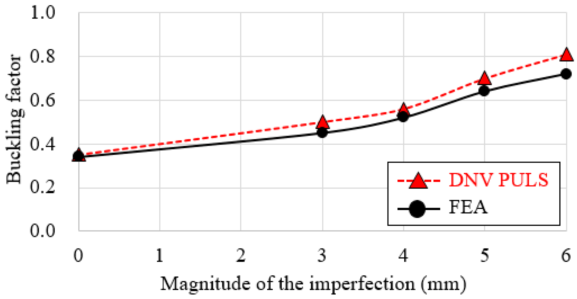
- Although the nonlinearity of the material was not considered, similarity in trend was confirmed when compared with the DNV analysis results.
2. Tanker Structural Design
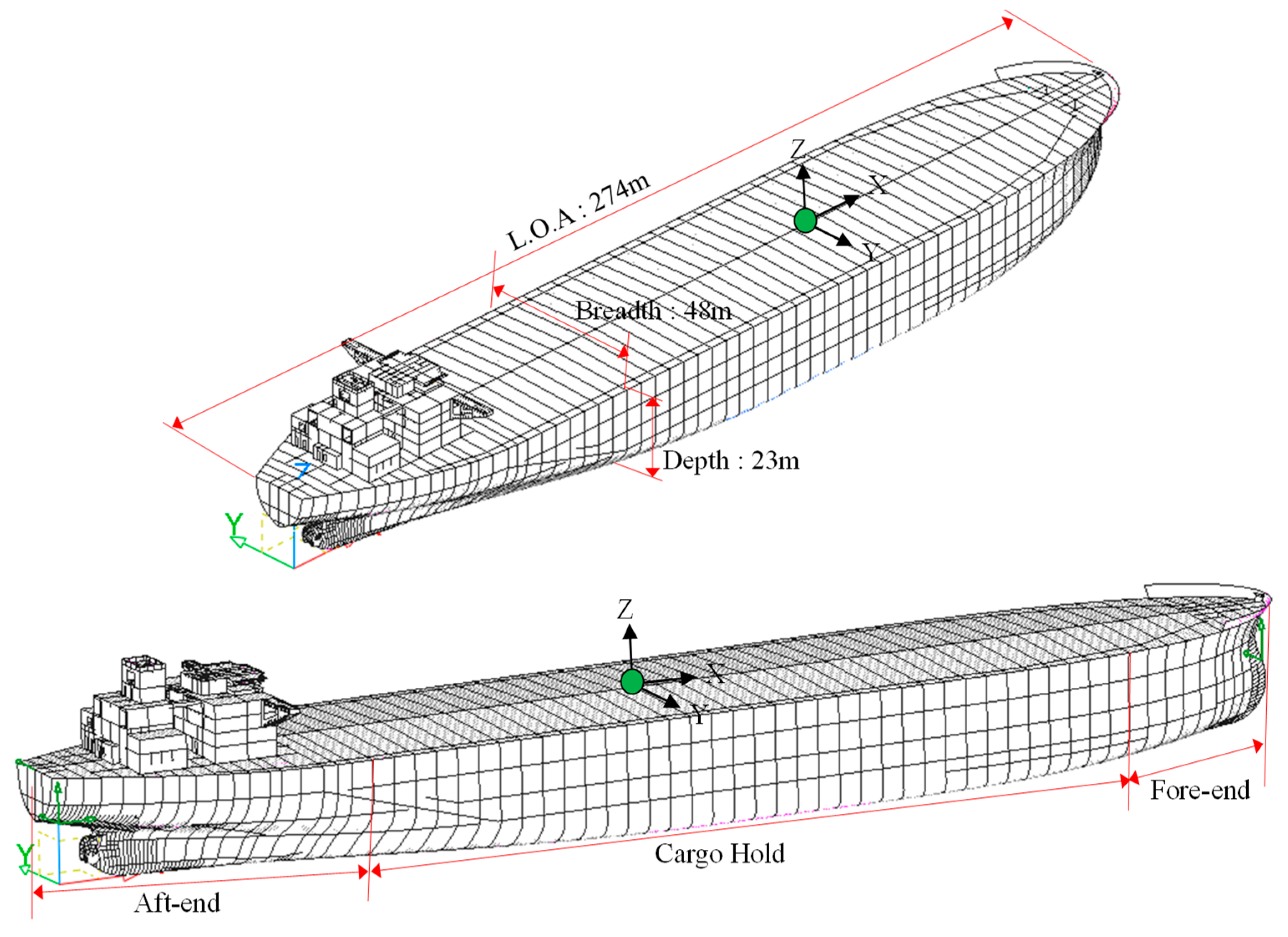
2.1. Main Specification and GA (General Arrangement)
2.2. Characteristics of Structural Design for the Stern Part
3. Finite Element Analysis and Discussion
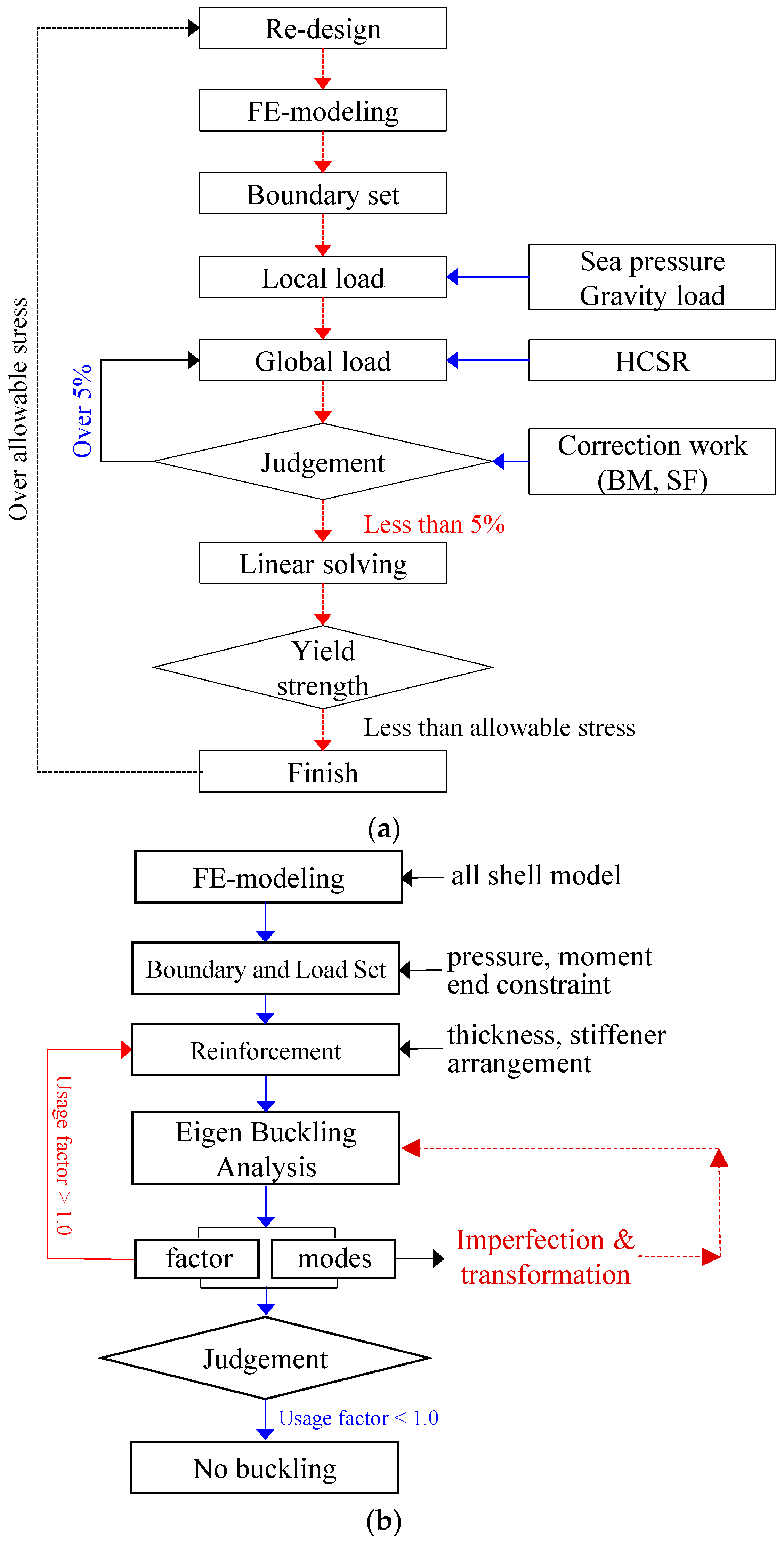
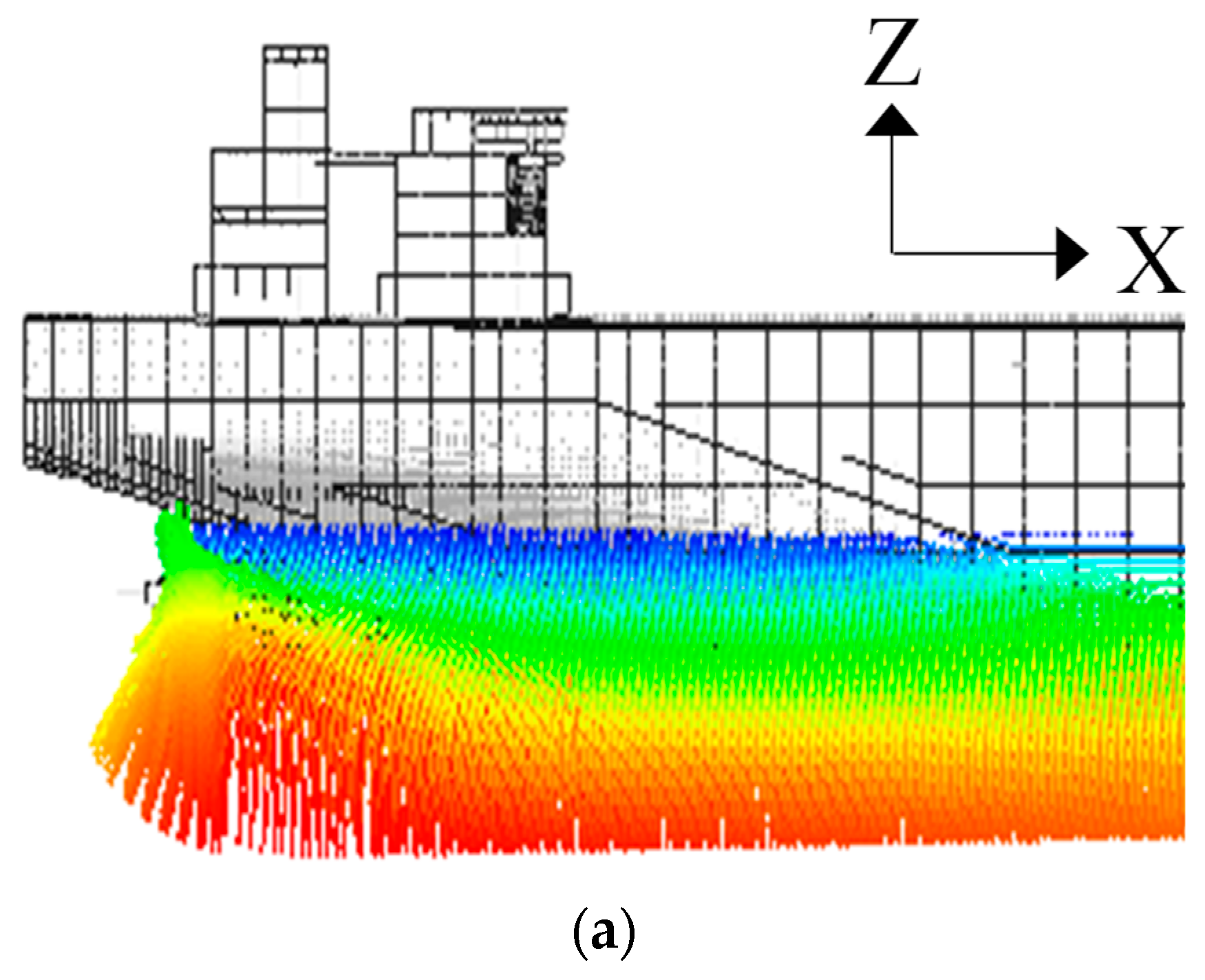
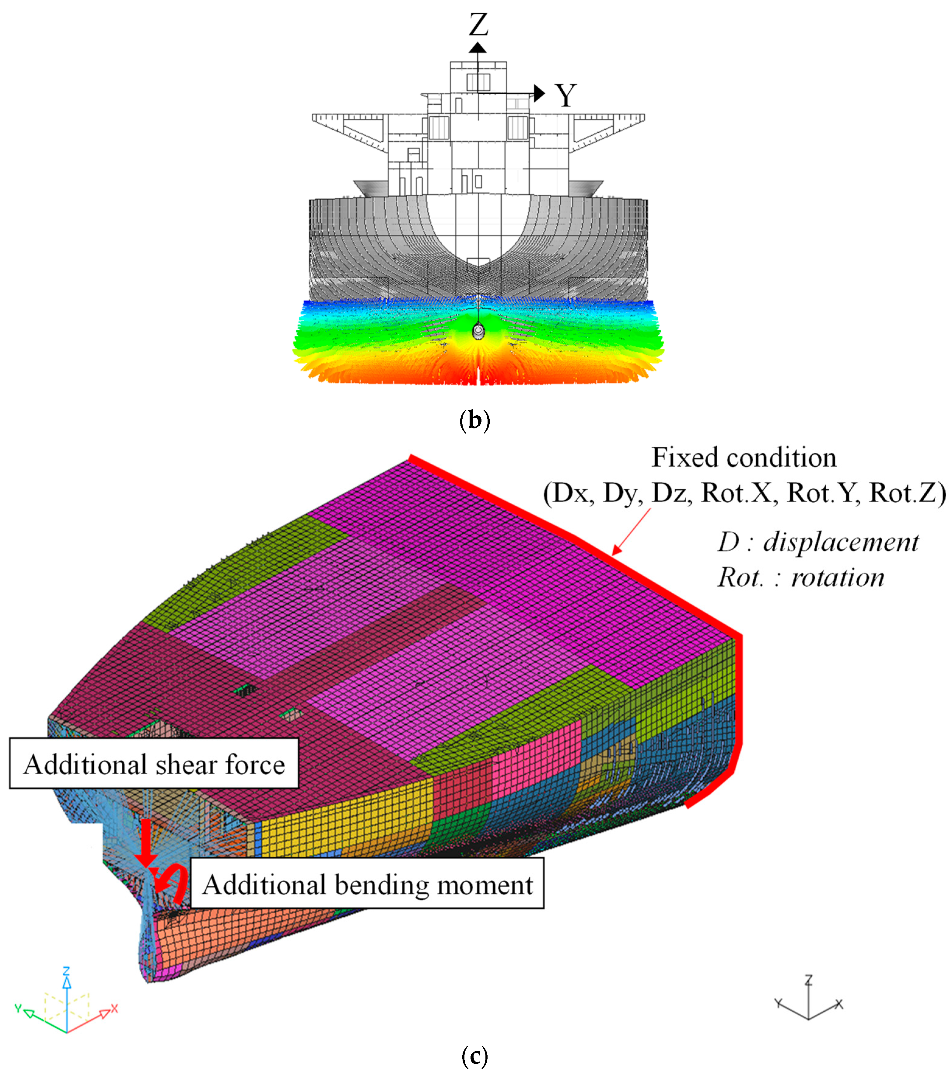
3.1. Modeling, Boundaries and Loading Conditions
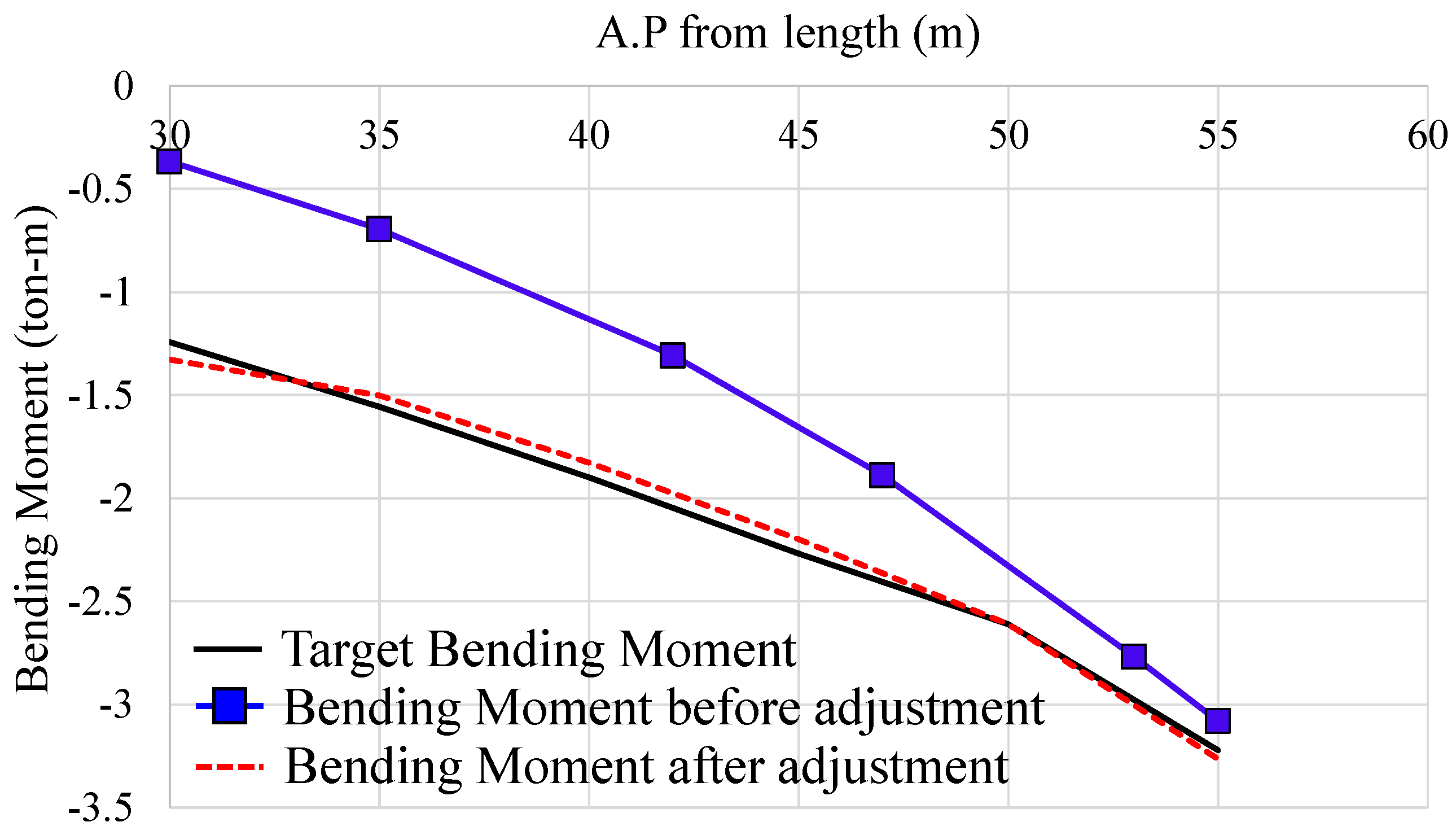
3.2. Process of Buckling Evaluation
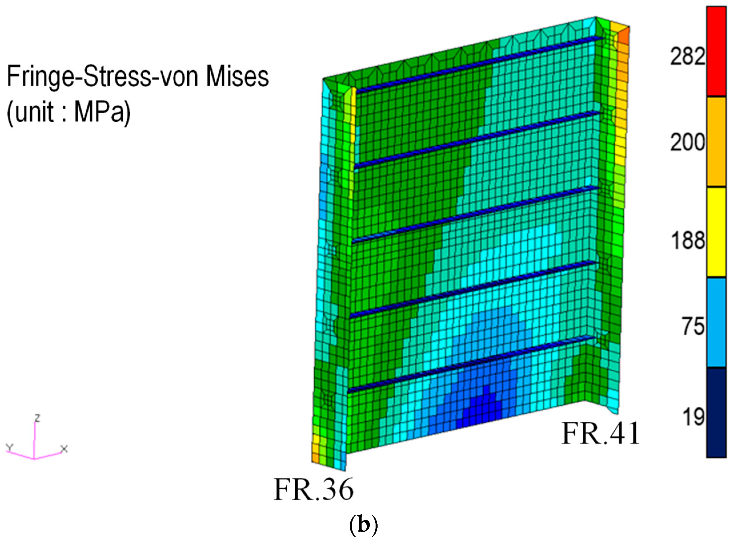
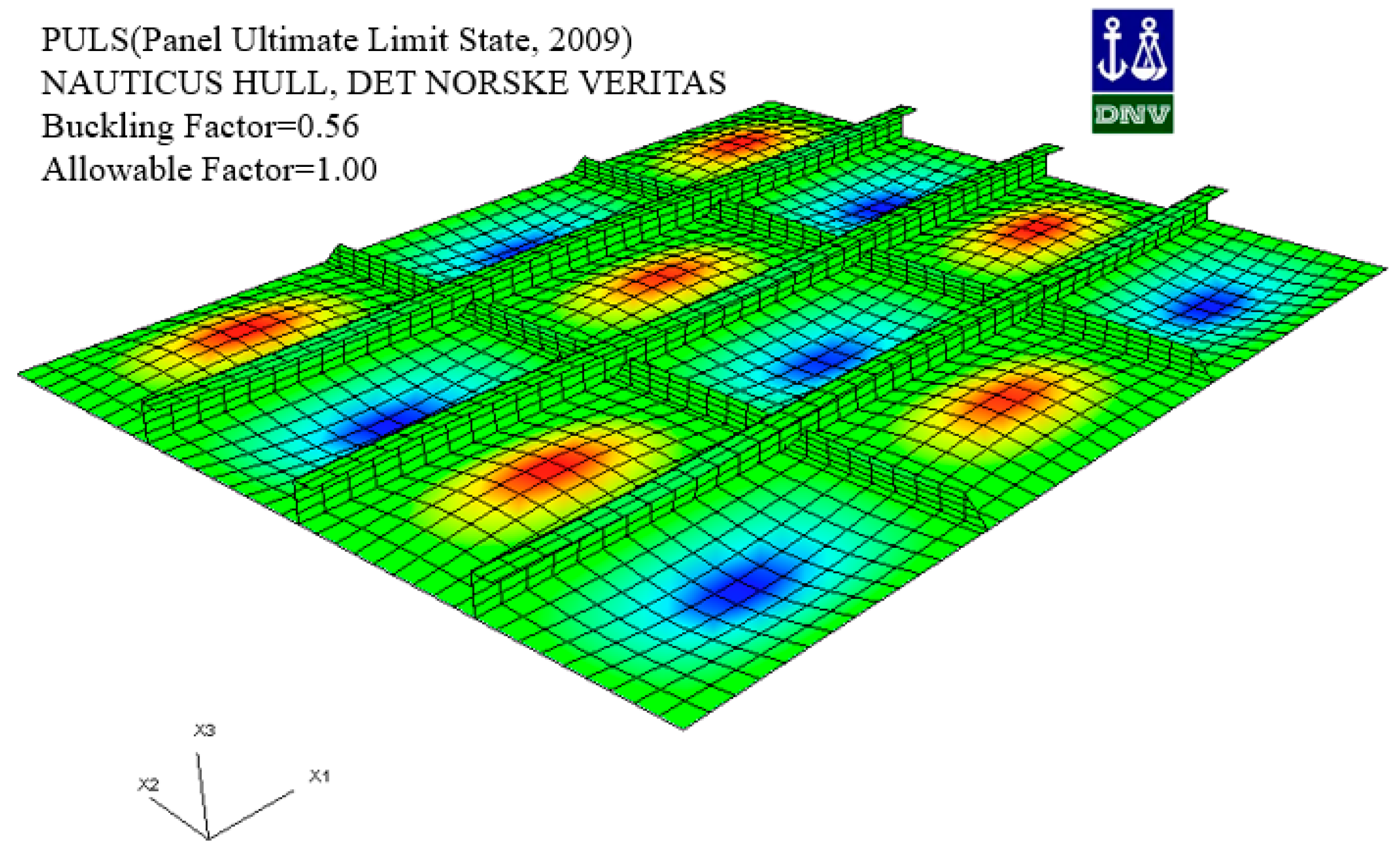
3.3. Buckling Evaluation and Strength Analysis of Stern
4. Concluding Remarks
- (1)
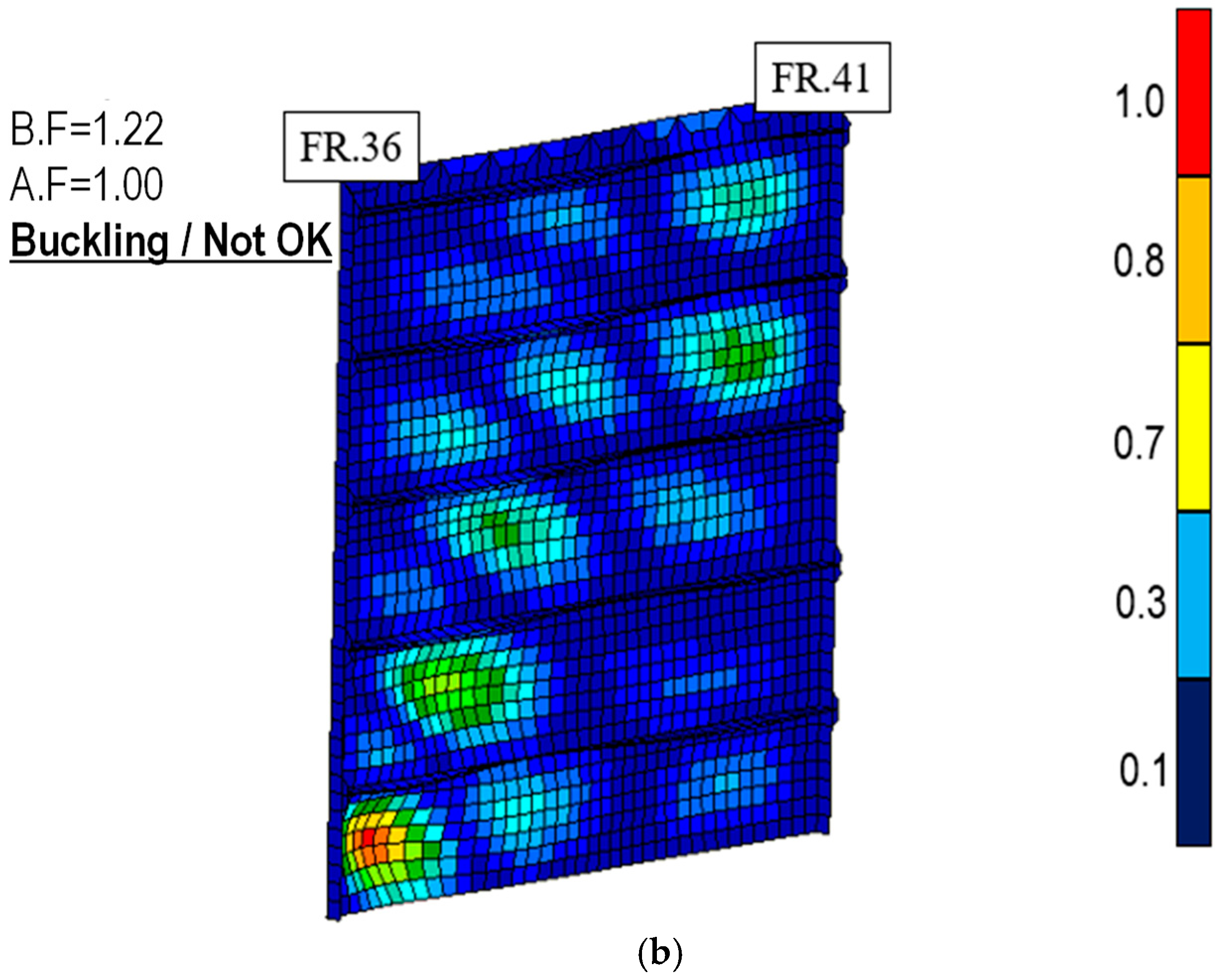
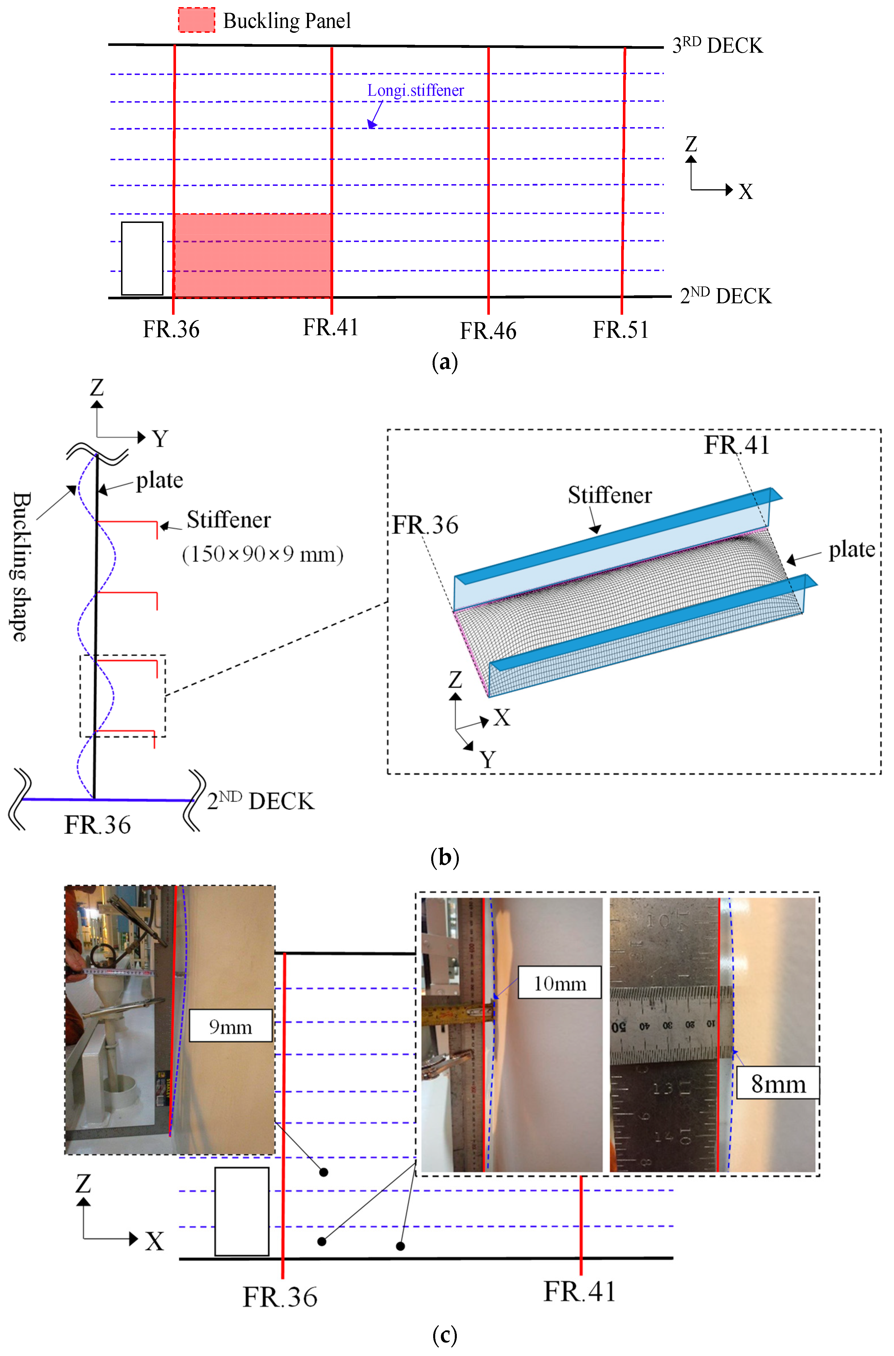
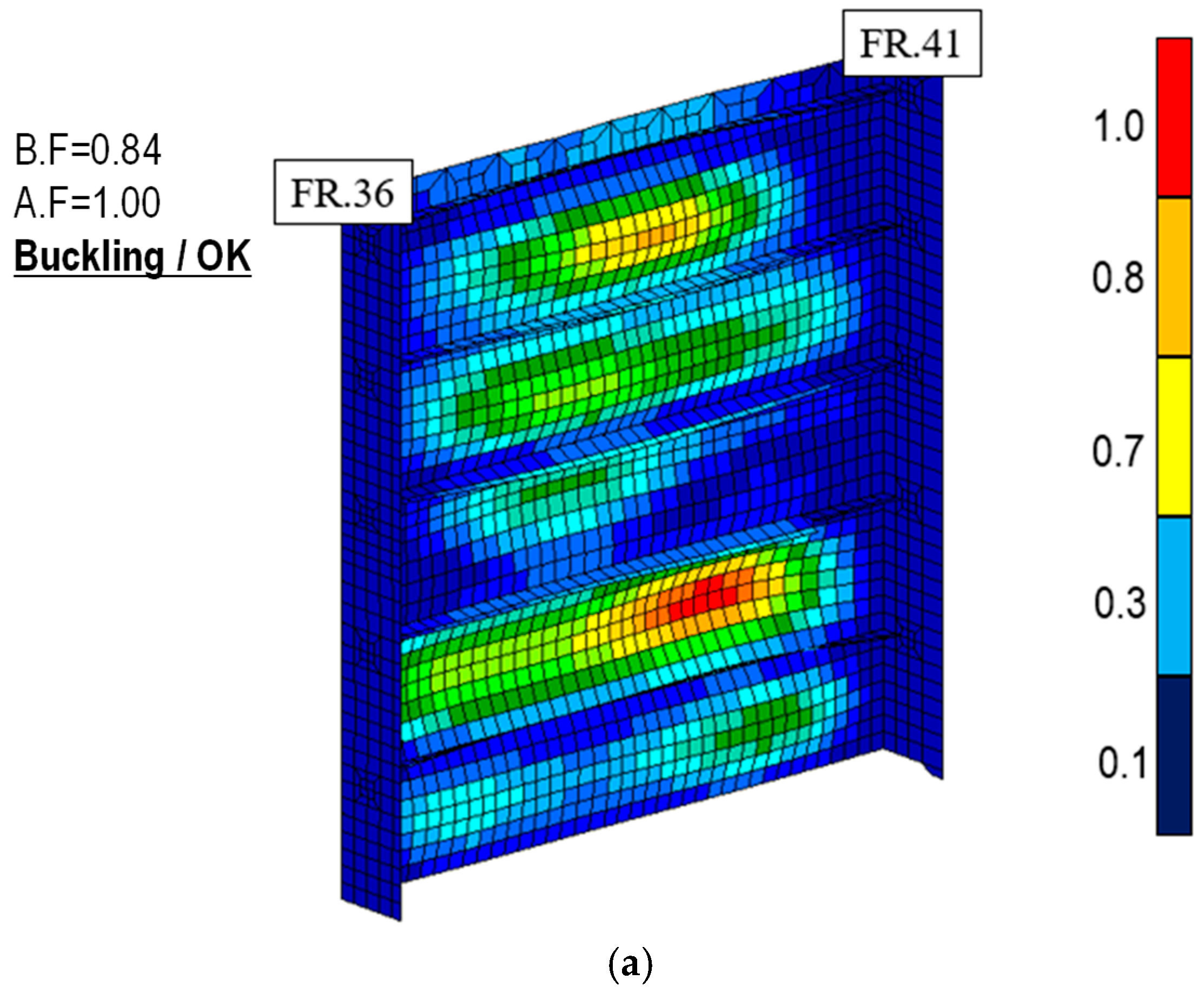
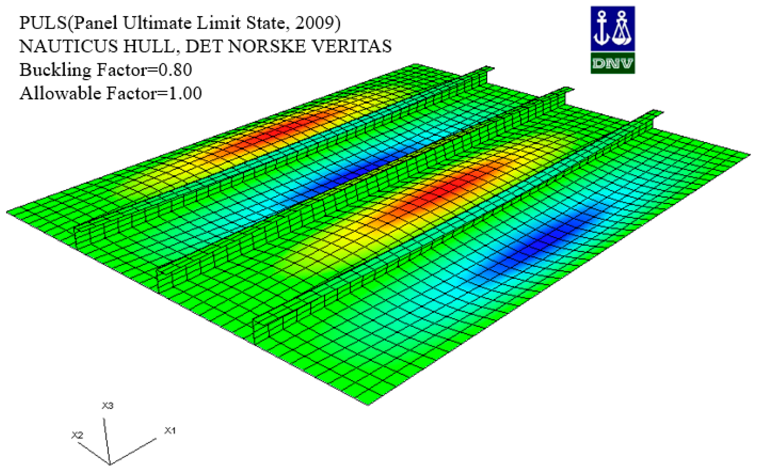
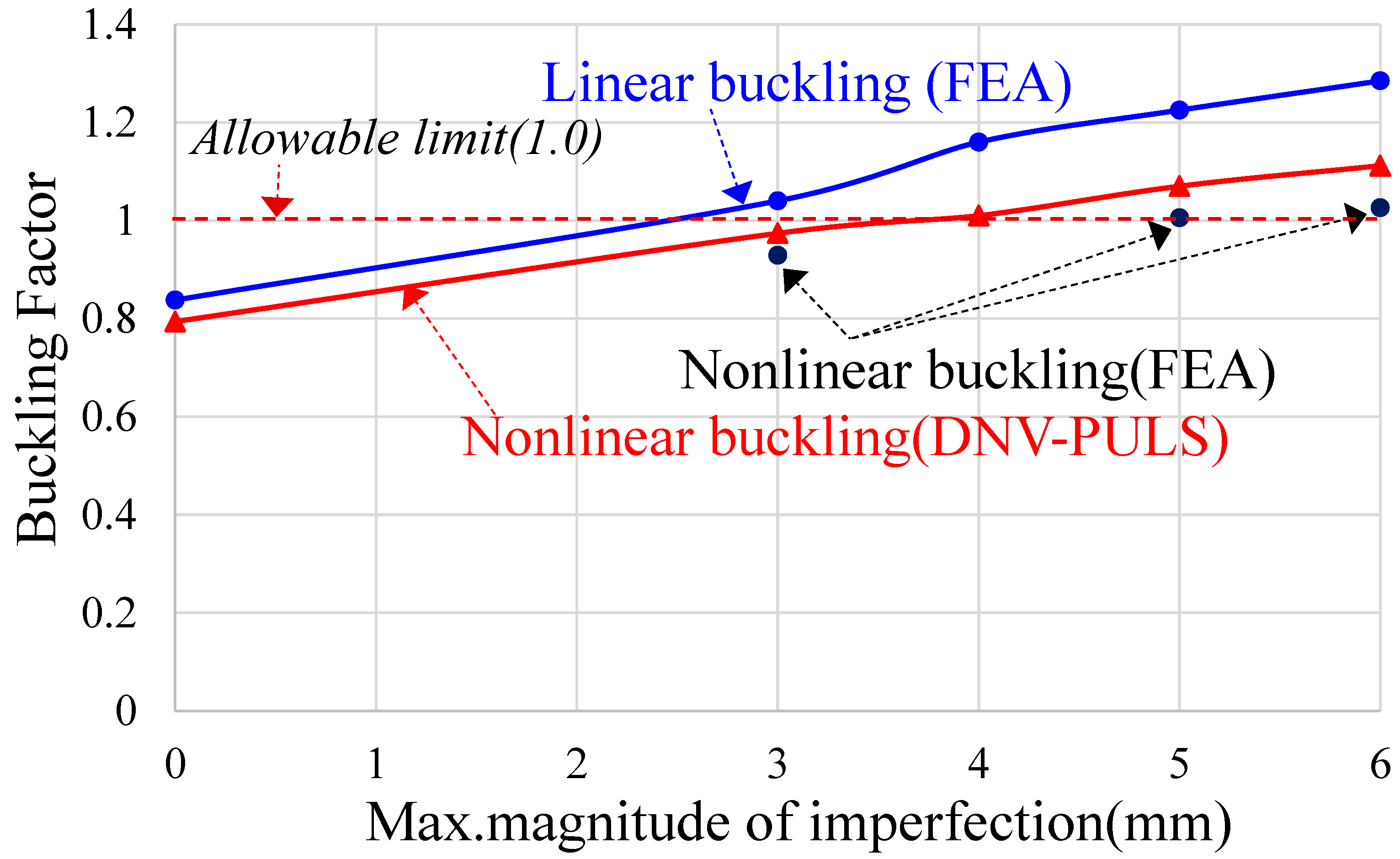
- When evaluating the buckling strength of a panel, even if the allowable criteria are met, there may be cases where buckling occurs during ship operation. One factor that can cause such damage is the initial deflection generated from welding.
- (2)
- As the magnitude of the initial deflection increases, it results in a higher evaluation of the hogging coefficient, which decreases the safety factor.
- (3)
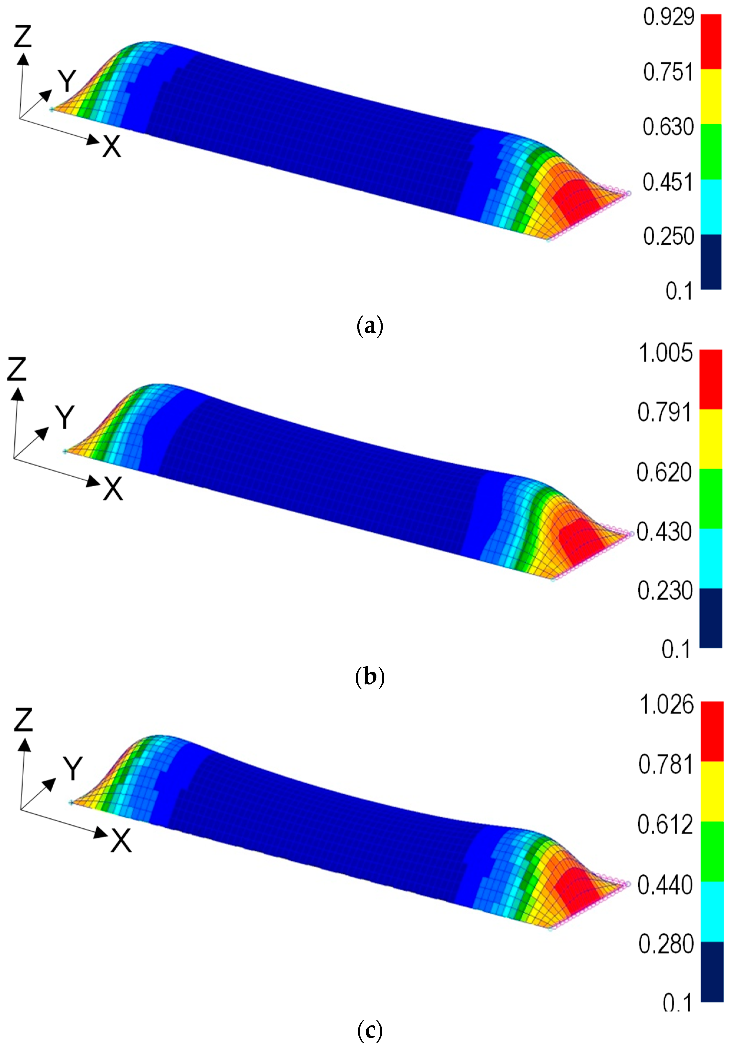
- The initial deflection effect can be possible to develop as a deformation of the node based on determined buckling mode. The determined buckling mode has the probability most similar to the collapsed shape.
- (4)
- In the FEA of the structure of the bow section, careful consideration should be given when determining boundary conditions and load application points, especially at locations with bulkheads. This is an important issue for implementing continuous behavior when the bow section experiences bending moments.
- (5)
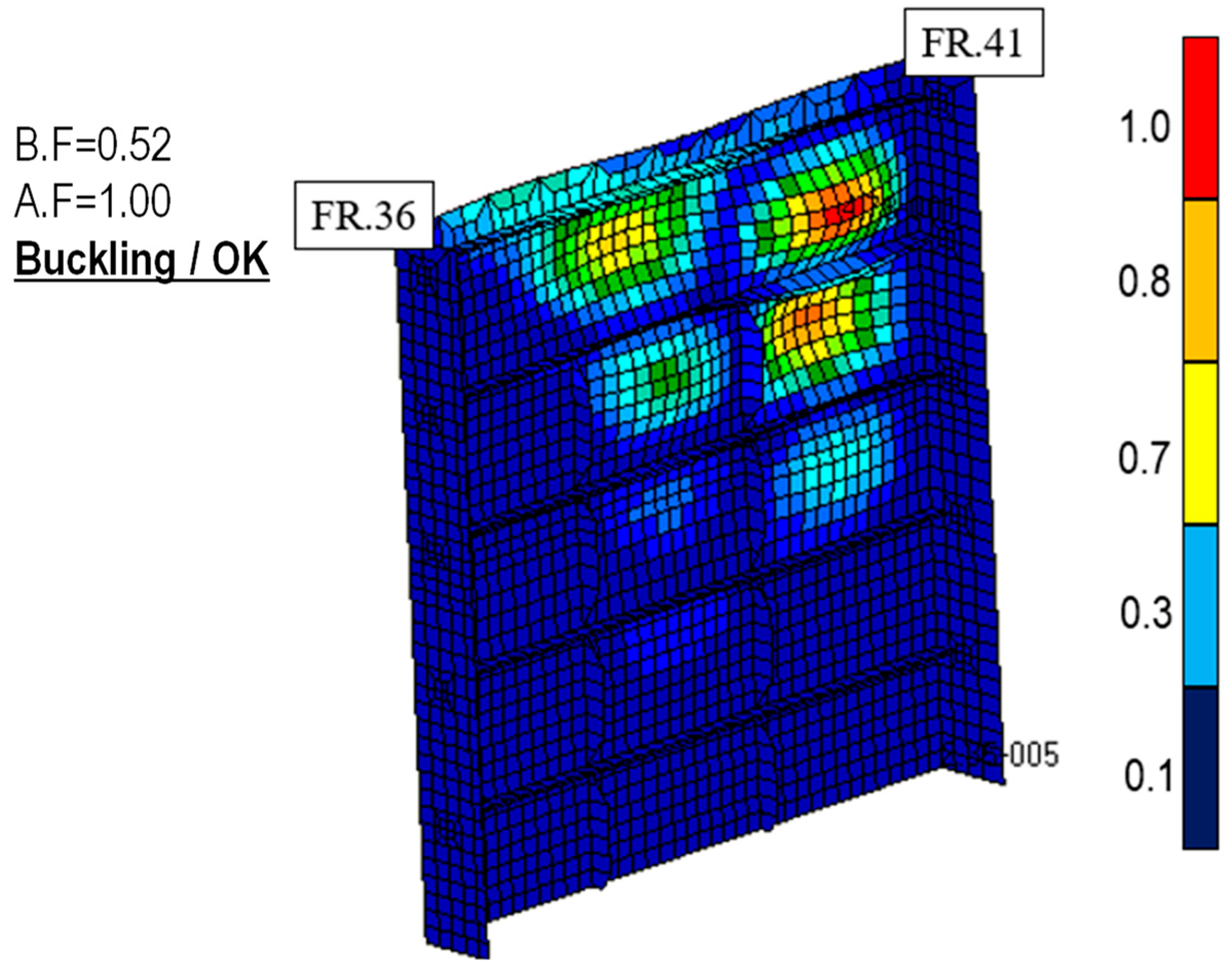
- Due to the response patterns of the analysis, modeling-based FEA and the limit state design-based PULS were similar, but the results of FEA showed a more conservative tendency under carling reinforcement.
- (6)
- In the case of analyzing using FE analysis modeling, load adjustments must be made to implement the maximum value identified in the longitudinal strength calculation, and this process plays an important role in determining the reliability of the analysis results.
- (7)
- The carling stiffener was added to change the buckling aspect ratio because the compressive load acts greatly in the width direction of the panel. This method is an efficient method to increase buckling safety without increasing the plate thickness.
- (8)
- As the magnitude of the initial imperfection increases, the buckling factor also increases. When conducting the buckling design of thin plates, it is necessary to secure a sufficient factor of safety under the assumption with imperfection by welding.
Author Contributions
Funding
Data Availability Statement
Conflicts of Interest
References
- Cho, S.R.; Song, I.C. Experimental Investigation on the Ultimate and Post-Ultimate Strength of Stiffened Plates under Axial Compression. J. Ship Ocean Technol. 2003, 7, 1–12. [Google Scholar]
- Oh, Y.C.; Ko, J.Y.; Lee, K.W. A Study on the Buckling and Ultimate Strength for Cylindrically Curved Plate subjected to Combined Load. In Proceedings of the Korean Institute of Navigation and Port Research Conference, Busan, Republic of Korea, 5–6 December 2007; Korean Institute of Navigation and Port Research: Busan, Republic of Korea; pp. 25–26. [Google Scholar]
- Park, J.S.; Ko, J.Y.; Oh, Y.C. Estimation of Buckling and Plastic Behaviour according to the Analysis Model of the Stiffened Plate. J. Korean Navig. Port Res. 2007, 31, 271–279. [Google Scholar]
- Jang, B.S.; Cho, H.Y. Comparison of Buckling Check Formulas and Optimal Design. J. Ocean Eng. Technol. 2009, 23, 71–78. [Google Scholar]
- Alashti, R.A.; Ahmadi, S.A. Buckling Analysis of Panels and Comparative Study on ABS and DNV Rules. Int. J. Marit. Technol. 2014, 2, 67–74. [Google Scholar]
- Radwan, M.; Kovesdi, B. Equivalent Geometric Imperfections for Local Buckling of Slender Box-section Columns. Period. Polytech. Civ. Eng. 2021, 65, 1279–1287. [Google Scholar] [CrossRef]
- Rörup, J.; Maciolowski, B.; Darie, I. FE-Based Strength Analysis of Ship Structures for a more Advanced Class Approval. In Proceedings of the PRADS2016, Copenhagen, Denmark, 4–8 September 2016; pp. 12–20. [Google Scholar]
- Rahman, M.M.; Kamol, R.S.; Islam, R. Structural Analysis of a Ship on Global Aspect using ANSYS. In Proceedings of the AIP Conference Proceedings; AIP Publishing: Long Island, NY, USA, 2017; pp. 1–9. [Google Scholar]
- Nassiraei, H.; Lotfollahi-Yaghin, M.A.; Ahmadi, H. Static strength of collar plate reinforced tubular T/Y-joints under brace compressive loading. J. Constr. Steel Res. 2016, 119, 39–49. [Google Scholar] [CrossRef]
- Pourostad, V.; Kuhlmann, U. Buckling resistance of stiffened panels subjected to constant transverse compression stresses. Proc. Civ. Eng. 2023, 6, 1799–1804. [Google Scholar] [CrossRef]
- Xu, B.; Wang, L.; Xiang, C.; Hand, Z. Analysis of Buckling Deformation for the Side Plate of Rectangular CSFT Column Based on Plate Theory with Bi-Axial Loads. Buildings 2022, 12, 626. [Google Scholar] [CrossRef]
- Chen, C.; Zhou, H.; Lv, Z.; Ge, X.; Xu, X. Experimental and Numerical Investigation of the Buckling Behaviour and Strength of Combined Opening Plate Girders in Passenger Ships. Metals 2023, 13, 1256. [Google Scholar] [CrossRef]
- Abedin, J.; Franklin, F.; Mahmud, S.I. Linear Longitudinal Strength Analysis of a Multipurpose Cargo Ship under Combined Bending and Torsional Load. J. Mar. Sci. Eng. 2024, 12, 59. [Google Scholar] [CrossRef]
- MSC Software. Patran 2012 User’s Guide; Chapter 6; Material Modeling: San Bruno, CA, USA, 2012; pp. 125–136. [Google Scholar]
- Common Structural Rules (CSR BC & OT). Section 3-Local Strength Analysis; Part 1, General Hull Requirement, Mesh Size; ICAS Req.: Hamburg, Germany, 2021; pp. 444–454. [Google Scholar]
- Paik, J.K.; Thayamballi, A.K. Ultimate Limit State Design of Steel-Plated Structures, 1st ed.; John Wiley & Sons, Ltd.: Hoboken, NJ, USA, 2003. [Google Scholar]
- International Association of Classification Societies (IACS). Shipbuilding and Remedial Quality Standard for New Construction; No.47 Ship Building and Repair Quality Standard; IACS Req.: Hamburg, Germany, 2012; pp. 6–14. [Google Scholar]
- HEXAGON. MSC Nastran 2018-Nonlinear (SOL 400) User’s Guide, Sec. 3, Nonlinear Option and Application; HEXAGON: Stockholm, Sweden, 2018; pp. 35–38. [Google Scholar]
- Det Norske Veritas (DNV). Nauticus Hull User Manual-Puls; Sec.3-Stiffened Plate Element; DNV: Oslo, Norway, 2006; pp. 23–41. [Google Scholar]


| Component | Dimension |
|---|---|
| Overall length (m) | 274.0 |
| Length between perpendiculars (m) | 264.0 |
| Overall breadth (m) | 48.0 |
| Depth of hull (m) | 23.0 |
| Draft (m) | 7.12 |
| Max. dead weight (ton) | 158,000 |
| Max. speed (knots) | 14 |
| Kinds of Members | Elastic Modulus (MPa) | Poisson’s Ratio | Elongation (%) | Yield Strength (MPa) | Tensile Ultimate Strength (MPa) |
|---|---|---|---|---|---|
| Side shell | 206,000 | 0.3 | 20 | 355 | 480 |
| Stiffener | 206,000 | 0.3 | 20 | 355 | 450 |
| Bulkhead | 206,000 | 0.3 | 22 | 315 | 480 |
| Weld metal | 206,000 | 0.3 | 20 | 670 | 720 |
| Kinds of Members | C | Mn | Si | P | S | Ni |
|---|---|---|---|---|---|---|
| Structural member | 0.18 | 1.0 | 0.20 | 0.035 | 0.035 | 0.40 |
| Weld metal | 0.06 | 1.40 | 0.40 | 0.011 | 0.010 | 2.50 |
| IMP. | B.F | A.F | Remarks |
|---|---|---|---|
| 0.0 mm | 0.84 | 1.00 | Ok |
| 3.0 mm | 1.03 | Not ok | |
| 4.0 mm | 1.16 | Not ok | |
| 5.0 mm | 1.22 | Not ok | |
| 6.0 mm | 1.28 | Not ok |
| IMP. | B.F | A.F | Remarks |
|---|---|---|---|
| 0.0 mm | 0.80 | 1.00 | Ok |
| 3.0 mm | 0.98 | Ok | |
| 4.0 mm | 1.03 | Not ok | |
| 5.0 mm | 1.08 | Not ok | |
| 6.0 mm | 1.12 | Not ok |
Disclaimer/Publisher’s Note: The statements, opinions and data contained in all publications are solely those of the individual author(s) and contributor(s) and not of MDPI and/or the editor(s). MDPI and/or the editor(s) disclaim responsibility for any injury to people or property resulting from any ideas, methods, instructions or products referred to in the content. |
© 2024 by the authors. Licensee MDPI, Basel, Switzerland. This article is an open access article distributed under the terms and conditions of the Creative Commons Attribution (CC BY) license (https://creativecommons.org/licenses/by/4.0/).
Share and Cite
Park, J.-S.; Yi, M.-S. Root Causes of Thin-Plate Buckling Damage at the Aft-End in Crude Oil Tanker and Verification through Buckling Analysis. Metals 2024, 14, 158. https://doi.org/10.3390/met14020158
Park J-S, Yi M-S. Root Causes of Thin-Plate Buckling Damage at the Aft-End in Crude Oil Tanker and Verification through Buckling Analysis. Metals. 2024; 14(2):158. https://doi.org/10.3390/met14020158
Chicago/Turabian StylePark, Joo-Shin, and Myung-Su Yi. 2024. "Root Causes of Thin-Plate Buckling Damage at the Aft-End in Crude Oil Tanker and Verification through Buckling Analysis" Metals 14, no. 2: 158. https://doi.org/10.3390/met14020158
APA StylePark, J.-S., & Yi, M.-S. (2024). Root Causes of Thin-Plate Buckling Damage at the Aft-End in Crude Oil Tanker and Verification through Buckling Analysis. Metals, 14(2), 158. https://doi.org/10.3390/met14020158