Article

Analysis of Edge Drop on Strip Due to Bending and Elastic Deformation of Back up Rolls in a Four-High Cold Mill

1
Facultad de Ingeniería Mecánica y Eléctrica Unidad Norte, Universidad Autónoma de Coahuila, Monclova 25750, Coahuila, Mexico
2
I.T. Morelia, Tecnológico Nacional de México, Av. Tecnológico 1500, Col. Lomas de Santiaguito, Morelia 58120, Michoacan, Mexico
*
Author to whom correspondence should be addressed.
Metals 2024, 14(2), 181; https://doi.org/10.3390/met14020181
Submission received: 16 December 2023 / Revised: 21 January 2024 / Accepted: 27 January 2024 / Published: 1 February 2024
(This article belongs to the Section Metal Casting, Forming and Heat Treatment)

Abstract

:
The superficial quality of the strip is a very important issue in steel production. Considering the dimensions, the thickness is one of the most important variables in the production of a strip. In the present study, the elastic curve of Back Up Rolls (BURs) is analyzed, considering them as simply supported beams as well as the effect of rolls on the profile of the strip, specifically in the strip edge producing edge drop. The analysis included theoretical and numerical measurements in the mill. The results showed that there is an instability zone of 76 mm in the strip edge, and this geometry is symmetrical in both ends of the strip. This study not only provides a theoretical basis for the edge drop, but also provides a basis for the understanding of deformation on rolls used in rolling mill processes and their effect on the thickness, profile, shape, and dimensional quality of strips. To reduce the edge drop and significantly improve the surface quality of the strip, it is suggested to complement the simulation by compensating for the elastic curve of BUR, in the process applying bending on Work Roll (WR) combined with the use of positive crowns on it.

Graphical Abstract

1. Introduction

The flatness, profile, and thickness of a strip are some of the most important variables of superficial quality of steel processed by flat rolling. Nowadays, there are many studies and developments of technology aiming to improve the quality of the strip. It is a complex matter because in a flat rolling process there are many variables which modify considerably the shape of the strip, mainly the flatness, profile, and thickness, which is most critical in the strip edge because it could cause the production of the strip to be out of standard or in extreme cases produce scrap coils due to the phenomenon known as drop end or edge drop. The edge drop is a little difference in the thickness of the strip between the center line and the strip edge which could be critical if it is not controlled thus causing a visual defect as shown in Figure 1.
Edge drop has been studied by some scientists, considering the importance of variables such as width of the strip, rolled material, taper roll contour, crown, etc. All of them used a FEM to analyze and propose a model of control for this phenomenon on a four-high cold rolling mill [1,2]. Chi et. al. [3] studied the same but applied to a four-high hot rolling mill; the difference between the studies was the influence of wear, which is more severe in hot rolling mills. The control and distribution of rolling forces is one of the variables that must be perfectly controlled [4,5], wherein the modern six-high tandem cold rolling mills and Sendzimir mills play an important role in controlling the edge drop control work roll (EDW). Cao et. al. [6] studied the use of a roll shifting system, and their conclusion was that cold rolling is the key process for the thin strip edge-drop control. Chang et al. [7] developed a model of roll stacks and strip deformation. They explained reasons for edge drop in the silicon strip cold rolling for the six- and four-high rolling mills and the edge drop was reduced considerably.
Edge drop and profile of strip are closely related; hence, the influence of the roll contours must be analyzed to understand and decrease this phenomenon. Guanghui et al. and Li et al. [8,9] studied the effect of smart crown on BUR for cold rolling mills and hot rolling mills, respectively. Wang et al. and Cao et al. [10,11] complement their studies using Continuous Variable Crown (CVC) in BUR and WR, and the conclusion of their studies was that the profile of the strip is closely related to contact pressure concentration between BUR and WR which is responsible for the deformation of the strip. Xiawei et.al. [12] confirmed the relationship between the profile of strips and the contours of WR. Since the transverse thickness distribution of the strip is strongly dependent on a roll’s shape, it is imperative to consider a work roll’s non-circular shape, particularly in thin strip edge drop, during the rolling process.
The edge drop is a problem located on the strip edge. Some other research focused in this area, such as the analysis of the pressure distribution on the strip edge in cold [13] and hot [14] rolling mills; in these cases, peaks of pressure were found near the edges of BURs. Cao et al. and Kong et al. [1,15] concluded that the pressure distribution changes with the strip width and can be improved by the dimensions of chamfers at the ends of BURs, whereby trying to produce flexion on WR and distribute the pressure to decrease the problem of profile and consequently the problem on strip edge. Yanlin et. al. [16] attribute the peaks of rolling pressure to the influence of temperature on the edge of the strip, and they analyzed the strip edge temperature drop and the influence of phases in electrical steel when there is a change in temperature.
The precision of thickness distribution and profile of strip are directly related to the rolling forces applied. Several scientists have developed analytical models for the prediction and control of strip profile in flat rolling [17,18], including in recent years the application of neural networks to improve the accuracy of roll forces [19,20]. Other scientists have studied strip profiles in asymmetrical rolling mills, investigating the influence of work roll crossing angle and work roll shifting; the results show that the thickness of the strip is consistent, and the profile of the strip is nearly flat [21].
Several investigations have focused on edge drop control and some improvements have been obtained; however, the problem of edge drop continues on the edge of the strip. The profile of the strip is the combination of all the variables described above, wherein to have a preliminary idea about the results, the understanding of bending in the rolls is an option. The WR is in contact with the strip, so the geometry of it will be stamped on the surface of the strip. However, the rolling forces are applied on BUR generating bending on it, which is transmitted by mechanical contact onto the strip; thus, it is necessary to complement the study with the theoretical analysis and numerical simulations of the elastic curve on BUR due to the distribution of rolling forces and geometrical characteristics. In the theoretical analysis, the obtained results of the equation for elastic curve were compared with simulations with the aid of FEM software (ANSYS 2023R2), validating the results with industrial data of compact X-ray thickness gauge from a four-high rolling mill, while looking for a new analysis process to establish the operational parameters in the function of the mechanical properties of the material and the actual shape of the rolls, in order to understand the edge drop defect. In this study, we propose a methodology to obtain quick results based on a simple theoretical model to aid in the decision-making in the plant.

2. Materials and Methods

The process of flat rolling for a four-high cold mill involves many variables of the operation process, geometrical dimensions, and mechanical properties of components implicated in the production of the strip. The analysis of elastic deformation of rolls and the application and transmission of rolling forces used to reduce the thickness of the strip is analyzed considering the system as a simply supported beam. The flat rolling process is a structural member that supports loads which are applied perpendicular to its longitudinal axis. For the determination of stress, distribution of pressure in this structural member and bending of rolls under rolling load, it is necessary to consider the equilibrium, the response of materials, and the geometry of the whole system. Figure 2 presents an illustration of the geometrical variables necessary for this analysis and the operational variables for the cold rolling process, which are defined for this particular case. The cold strip stand mill consists of four rolls, two BUR and two WR, whereby the mechanical and metallurgical properties of rolls and strip are indicated in Table 1. The structural mechanism of the flat rolling process is considered as a simply supported beam, analyzing the elastic deformation of rolls considering +0.039 mm crown on BUR and +0.101 mm on WR, chamfer of 76.2 mm × 6.604 mm on BUR, and no taper on WR.
A 3D-FEM was employed to simulate the rolling process, using the ANSYS Mechanical Static Structural Software (ANSYS 2023R2) considering the dimensions of mechanical components of the process. In the bearing areas of top BUR, the rolling forces are uniformly distributed. Elastic and plastic deformation is incorporated in the simulation by activating the large deflection option in ANSYS Mechanical. Due to the magnitude of the loads, the rolls undergo only elastic deformation while the strip undergoes plastic and elastic deformation. General joints in the lateral face of the rolls allowed only vertical movement in the direction of rolling force. The bottom rolls are fixed, and the boundary conditions of the simulation are shown in Figure 2. An element size of 0.05 m was used in an intelligent mesh generated by ANSYS, as shown in Figure 3. A SOLID186 element with three degrees of freedom per node (translation in the nodal x, y, and z directions) was used for the mesh defined by 20 nodes. Depending on the complexity of the geometry, this element can take hexahedral, tetrahedral, pyramid, or prism shape. The mesh had a total of 980,438 nodes and 544,956 elements. The contact region mesh (BUR-WR-Strip) was considered with a bonded system, and no sliding or separation between face and edges is implement without penetration [22].
Results obtained with theoretical analysis and simulation with FEM will be validated with results obtained from a compact X-ray thickness gauge installed in the last stand of a four-high cold mill. Thickness and Profile Gauge System with X-rays operate on the principle of transmission radiation. X-ray or isotope radiation emitted by a radiation source passes through the strip. A detector located on the opposite side of the strip measures the radiation intensity. The strip material absorbs some of the radiation and the remaining radiation reaches the detector. An ionization current proportional to the thickness of the strip is generated by the intensity of the remaining radiation. A measuring transducer converts the current into a digital signal and is transmitted to a gauge signal-processing computer. A computer in the control pulpit receives the signal from the gauge and shows the thickness of the strip.

3. Results

3.1. Theorical Analysis

The principal problem of mechanical materials is the determination of relationships between stresses and deformation produced by the applied forces in a structure or mechanical component. The bending study is complicated because the effect of applied forces is variable along the beam, and these variables are clearly identified as shear forces, bending moment, and elastic curve.
For our analysis, the flat rolling process is a statically determinate system of simply supported beam, such as is shown in Figure 4a, where the uniformly distributed load is applied on the strip while on the rolls several stresses are produced, and the deformation must be controlled to minimize edge drop. For our case, the two rolling forces of 4894 kN distribute along the strip width of 520.7 mm, resulting in the uniformly distributed load of 18,793.93 kN/m. The sections of the beams where load conditions are variable are normally called points of change or points of discontinuity, identified with the letters A, B, C, and D.
For any plane a-a, located along the segment A-B in the beam, the shear force maintained the constant value of 4894 kN, and the bending moment is defined by the following equation:
M A - B = R f A x
In the case of planes b-b, located in the section between points B and C, the shear forces are varying from 4894 kN to −4894 kN, and the bending moment is defined by the following equation:
M B - C = R f A x W 2 x α 2
To complete the analysis of the beam, considering any plane c-c, located along the segment C-D, the shear force maintained the constant value of −4894 kN, and the equation for the bending moment is determined with the following equation:
M = R f A x W 2 x α 2 + W 2 x α β 2
where α = 0.5778   m   (segment A-B in Figure 4a) and   β = 0.5207   m   (segment B-C in Figure 4a).
Considering that the differential equation of the elastic curve is the following:
E I d 2 y d 2 x = M
Integrating Equation (4), supposing that EI is constant, we find the slope of the bending moment equation, which is the following:
E I d y d x = M d x + C 1
Solving the equation for our case, the equation is the following:
E I d y d x = R f A x 2 2 W 6 x α 3 + W 6 x α β 3 + C 1
In this expression, the · takes a value of zero if the result inside is negative. Integrating one more time the slope of the bending moment equation, we obtain the elastic curve, which is the following:
E I y = M d x d x + C 1 x + C 2
Solving the double integration for our case, the final equation of the elastic curve is the following:
E I y = R f A x 3 6 W 24 x α 4 + W 24 x α β 4 + C 1 x + C 2
The numerical values of the constants of integration C1 y C2 are calculated according to boundary conditions.
The boundary conditions are as follows:
y = 0 ; a t   x = 0  
y = 0 ; a t   x = L R f
Applying the boundary conditions, the constants are as follows:
C 2 = 0 ;
C 1 = R f A L R f 2 6 + W 24   L R f L R f α 4 W 24   L R f L R f α β 4
The present study analyzed the rolling mill process, considering it as a simply supported beam; however, in the centerline the shear force is zero, meaning that it could be analyzed as a cantilever beam system while obtaining similar results.
The shear forces shown in Figure 4b are used for calculating the bending moment. The most important area of the analysis is the section between points B and C (strip edge), because at this zone the shear forces are changing from 4894 kN to −4894 kN. At this zone the phenomenon of reduction of strip by cold rolling is achieved, as shown in Figure 4c. At points B and C, the bending moment is lower than that at the center line mill, and there is a difference of 637 kN-m which represents 18.37% of the total bending moment. In the case of the graph shown in Figure 4d, the elastic curve has a similar result, whereby the difference of bending from strip edge to centerline mill is 0.024 mm, which represents 12.24% of total bending.

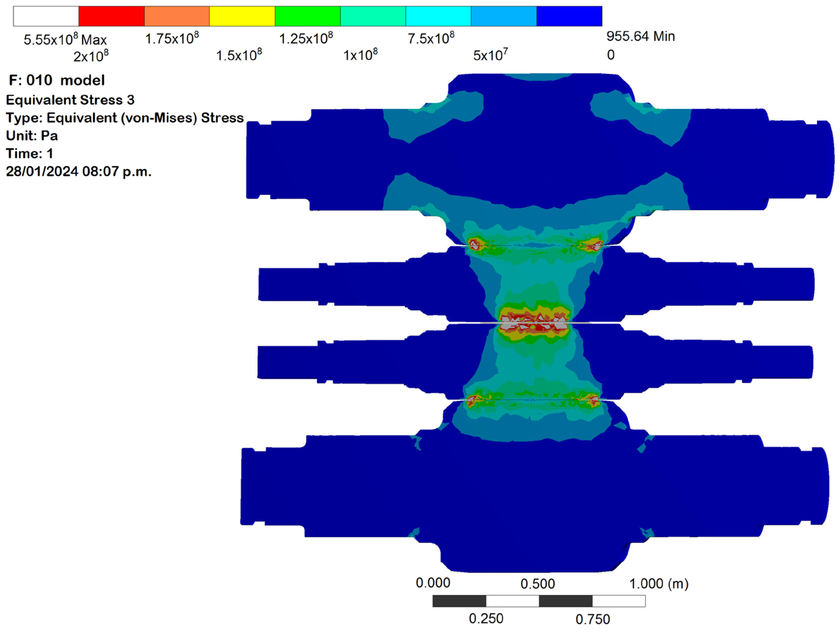
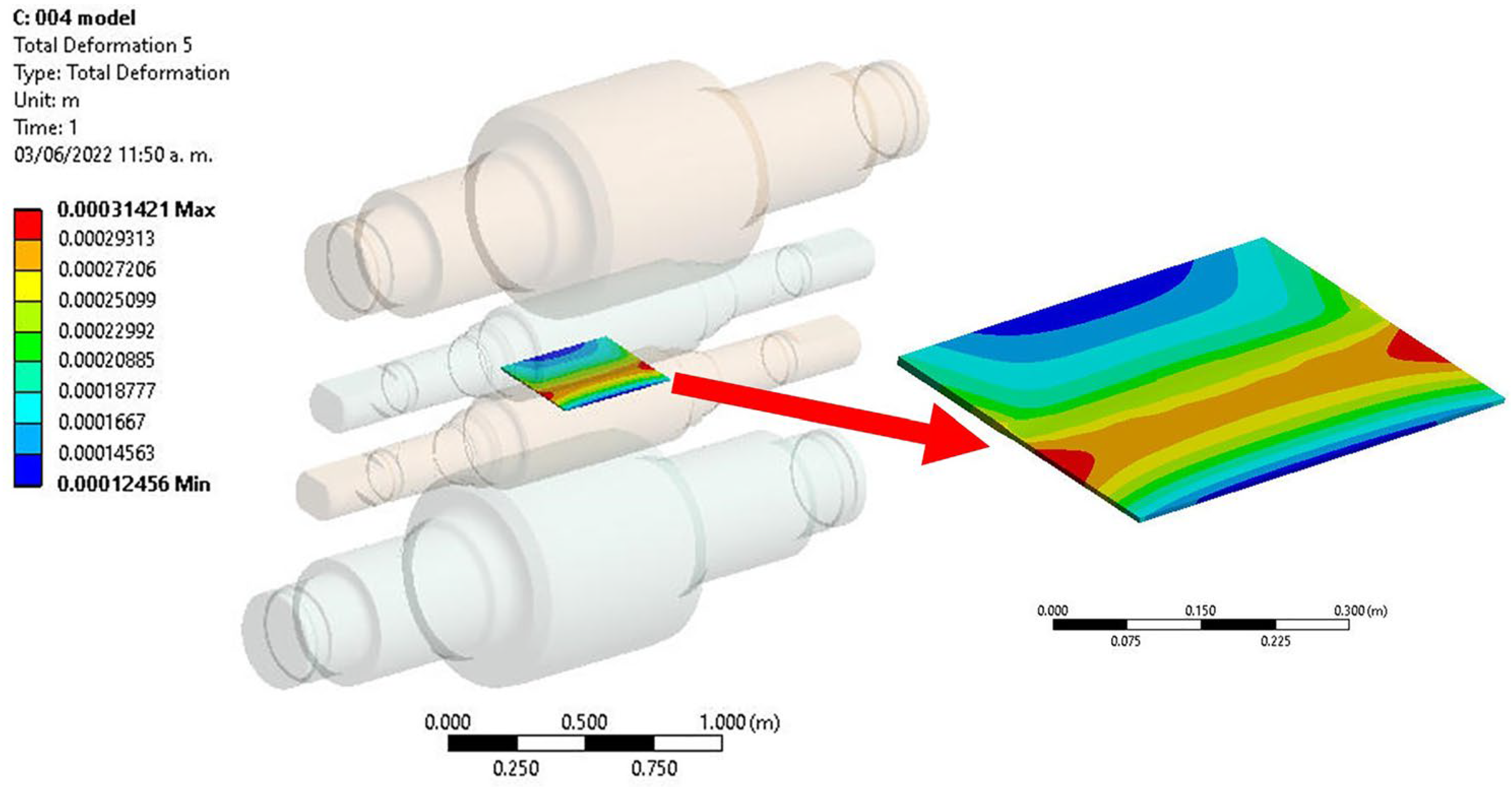
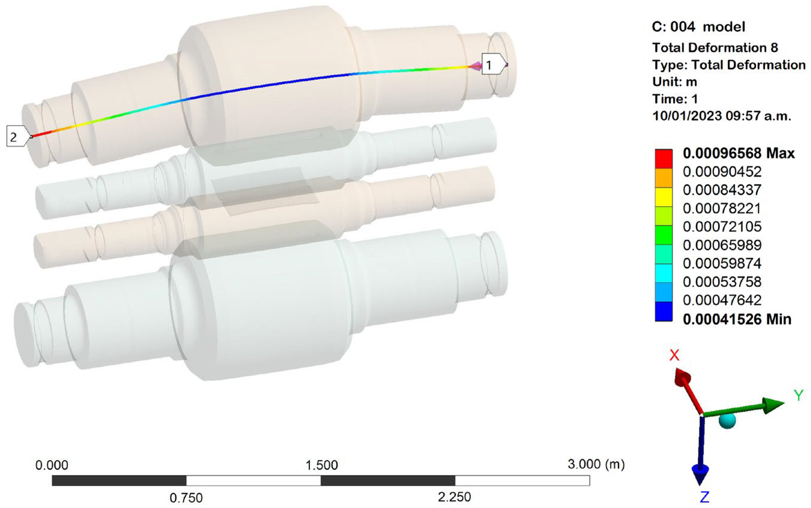
3.2. Results of the Simulation

Using the variables of production for the cold strip mill described above, this study is complemented with the distribution of stress and deformation of the strip. In the case of the analysis of stress, Figure 5 shows the distribution of stress, wherein we can observe maximum stress values of 200 MPa located in two contact zones; the first contact zone is between BUR and WR, and the second one is between the strip and WR; for the analysis of edge drop, the most important zone of the analysis is in the contact of WR with the strip. In this case, the illustration in Figure 5 shows the stress concentration in the strip edge; therefore, in this area it is normal to find the edge drop on the strip; it can be confirmed with the results of the simulation shown in a schematic illustration in Figure 6, where we can observe the maximum deformation on the strip edge.
The thickness of the strip obtained from the FEM simulation is shown in Figure 7. This illustration shows instability in all the width of the strip; however, in the strip edge the variation is more critical, the zone of instability has a length of approximately 76 mm, and the effect is similar on both edges of the strip. Comparing the last three figures of stress, deformation, and thickness, all of them confirm that the strip edges revealed a zone of stress concentration and instability causing the edge drop.
To obtain an idea of the elastic curve during the cold rolling process, Figure 8 shows the illustration of bending in the axis of BUR. In this illustration, we can see the maximum bending and deformation at the end of the neck for BUR; however, the zone of interest for the process of rolling and quality of the shape in the strip is the zone of contact between the rolls and the strip, particularly in this case in the strip width of 520.7 mm. The simulation results of this zone are compared in Figure 9 with the graph of the mathematical equation of elastic curve obtained from the theoretical analysis. The values have a small difference of 0.08 mm; however, the geometry of them is exactly the same, and this means that the simulation analysis of the rolling process for a four-high cold mill is in agreement with the theoretical analysis of the process as a simply supported beam.

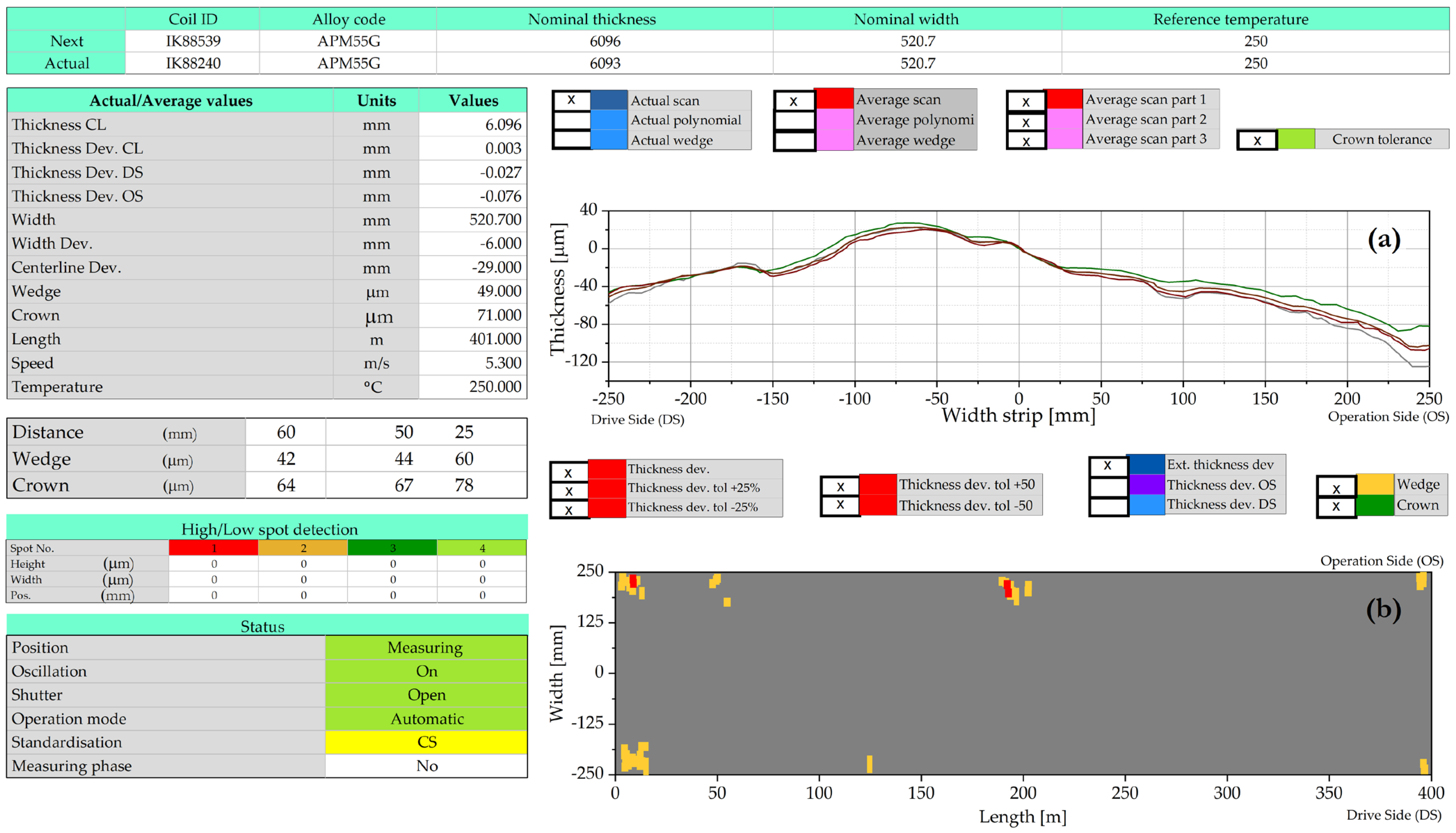
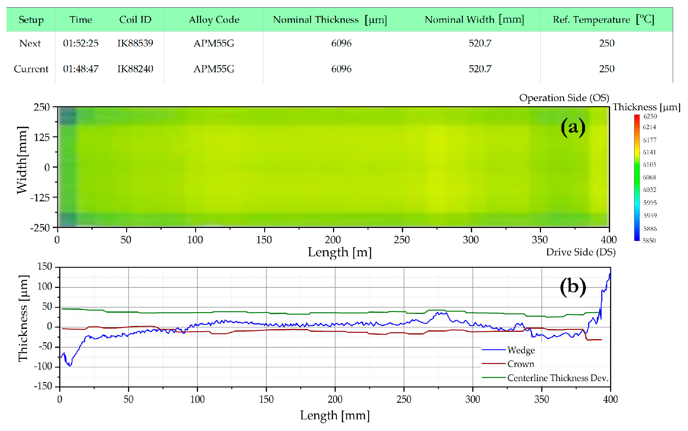
3.3. Industrial Results

The industrial validation of the scientific analysis is an essential tool to guarantee the efficiency of the study, as the objective of the industrial validation is to prove that the obtained results with simulation and calculated values of edge drop agree with the industrial results obtained with the use of compact X-ray thickness gauge installed in a four-high cold mill. Figure 10a displays an illustration of the average of profile width showing that in the strip there is a thickness variation of 180 µm, with more instability in the Operation Side (OS, −140 µm) than in the Drive Side (DS, 40 µm). It is confirmed in Figure 10b with the marks of alarm, showing that in the total coil length of 400 m the thickness deviation appears more frequently on OS than on DS.
According to the results of the graphs from control pulpit, the problem of edge drop is always critical in the strip edge, and it is confirmed in the images in Figure 11. Figure 11a illustrates in the strip edge a little difference in the color. It represents a value close to 73 µm which is considered as edge drop, indicating that there is a disturbance on the thickness of the strip of almost 70 mm width. Moreover, the most critical case is in the entry and tail of coils, because in this interval of time there is an instability, as shown in Figure 11b, which is almost 20 m long in the entry and tail of the coils.

4. Discussion

Rolling forces applied on the bearing zone produce the elastic curve on BUR and consequently the shape of the strip, affecting the flatness, profile, and reduction in thickness. To distribute the pressure and avoid the stress concentration variables such as taper roll contour, crown, and chamfers at the ends have been studied; however, the problem of drop edge continues on the strip edge. The points of change or points of discontinuity B and C correspond to the strip edge (see Figure 4c,d). Note that the geometry of curves for bending moment and elastic curve are symmetrically opposite, but the profile is similar. Analyzing the points of change B and C, the results showed that the difference between the values in the centerline and those of the strip edge are very similar for bending moment and elastic curve, at 18.37% vs. 12.24%, respectively.
The stress concentration indicates instability and consequently alterations on the flatness and thickness of the strip. The images of the simulation shown in Figure 5 are in agreement with the edge drop obtained in the strip edge shown in Figure 10b and Figure 11a. Moreover, the 76 mm width of instability obtained by simulation in the edges shown in Figure 7 matches the results of edge drop shown in Figure 10b and Figure 11a.
The geometry of the elastic curve obtained on BUR with theorical analysis shown in Figure 4d has the same profile of the elastic curve obtained by simulation software according to the image shown in Figure 8. WR transmits the mechanical contact and compresses the thickness of the strip generating the profile of strip shown in Figure 10a. It has a similar appearance with the profile of elastic curves described heretofore, which means that the mathematical model, simulation, and industrial results are in agreement, as can be observed in Figure 12, where the thickness deviation from Figure 10 is compared with the analytical thickness deviation obtained from Figure 9. The thickness deviation for the analytical method was calculated as the sum of the deflection of top and bottom rolls. The concordance between approaches does not match perfectly, since in industrial practice it is difficult (or even impossible) to meet the symmetrical conditions. However, the results are very acceptable considering the order of magnitude (µm) and simplicity of the theoretical analysis.
According to the results obtained with the theoretical analysis and simulation software, there is a relationship between all the analyzed variables with edge drop produced on the strip. It is critical in the strip edge or points B and C as established in this study. Moreover, industrial results indicated that edge drop is more critical in the entry and tail of the coil, due to a disturbance of the thickness and the instability of the process.
The geometry of theoretical and simulated results for elastic curve shown in Figure 9 are similar and symmetric on both sides of the strip. It is due to the conditions, considered as an ideal system. However, in the geometry of the strip shown in Figure 10a, there is a thickness deviation that appears more frequently in OS than in DS. Rongrong et. al. [23] described the destabilizing of a rolling mill due to the evident energy exchange process between BUR and WR, which is transmitted to the strip.

5. Conclusions

The bending phenomena of BUR in cold rolling was analyzed to understand edge drop using analytical calculations and numerical simulations and the results were compared with plant measurements. The aim of this research was to increase the understanding of the phenomenon and recreate it virtually to obtain a fast calculation to make operational decisions using a theoretical model of simply supported beam. The model predicts the thickness deviation of the strip quite well despite the simplicity of the expressions. The main suggestions are drawn as follows:
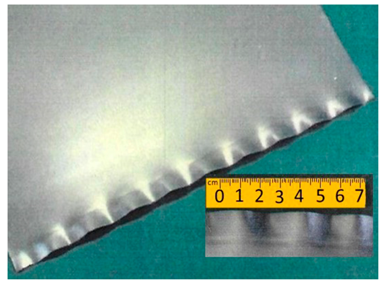
  • As a result of the distribution of forces and stress distribution on the trip, the phenomenon of edge drop in the cold rolling process is common, since the profile of the strip takes the geometry of the elastic curve of BUR. To reduce it, it is necessary to carry out an analysis of every roll mill as a particular case, looking to decrease or invert the elastic curve of BUR.
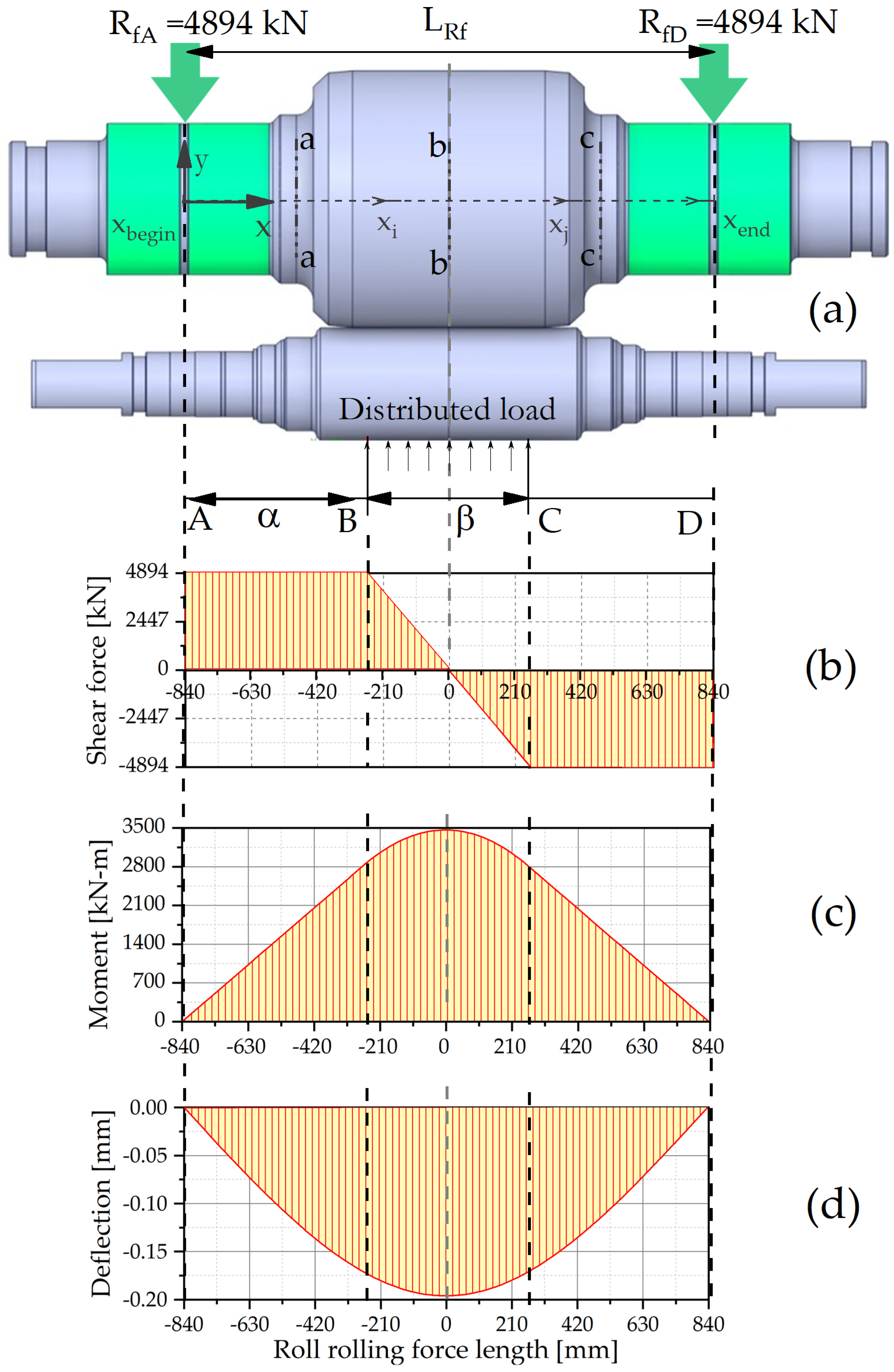
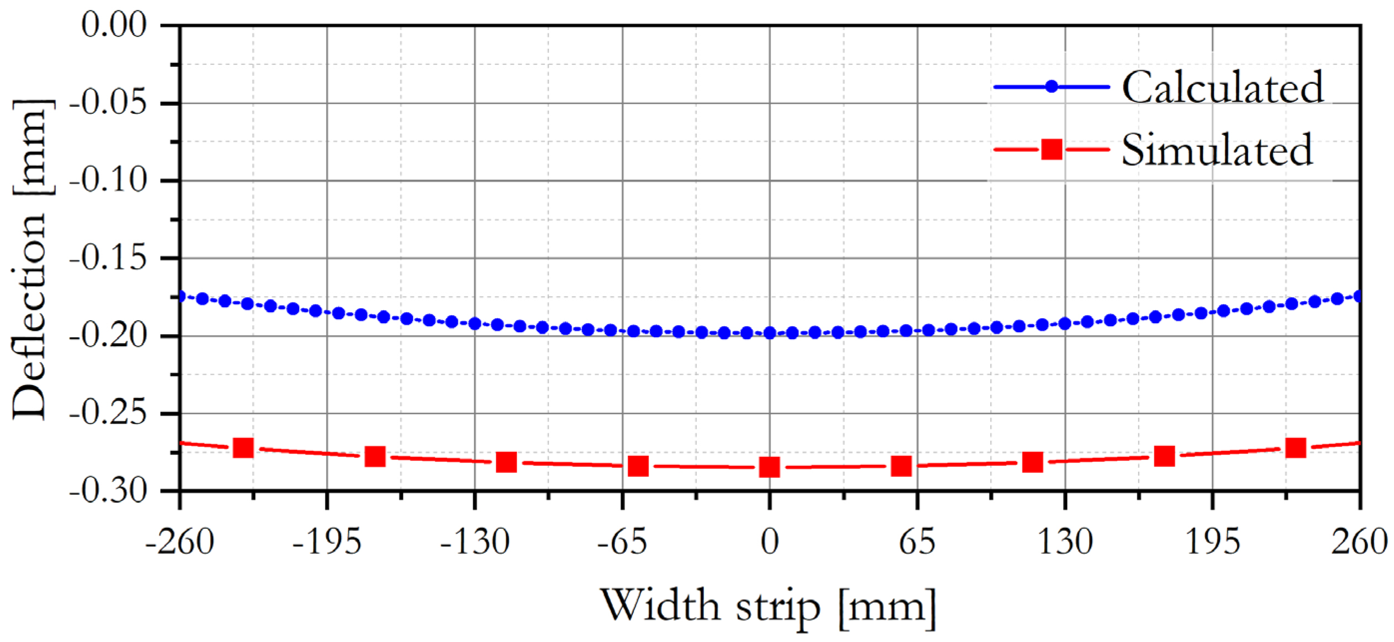
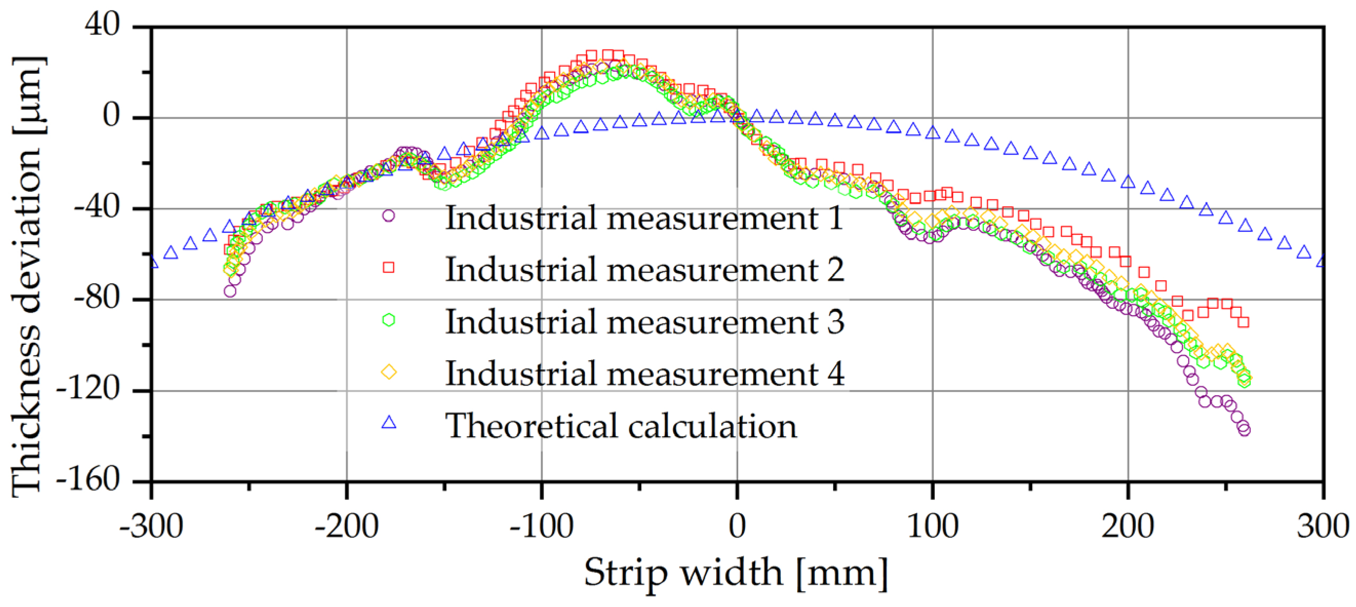
  • The evidence documents that the mathematical analysis and simulation are validated on an industrial scale and consistent results can be obtained, which helps considerably to understand the principle of edge drop. The elastic curve is a function of rolling mill design, mechanical properties of rolls, and operation variables for the rolling process. The problem of edge drop is a function of these variables, and to decrease the elastic curve, the use of adequate crowns of rolls is suggested for each rolling mill combined with the use of roll bending moment.
  • To decrease the elastic curve and consequently edge drop, it is recommendable to use BURs in a six-high cold mill over BURs in a four-high cold mill, combined with the use of positive crowns.

Author Contributions

Conceptualization, R.S. and I.C.; methodology, I.C. and A.P.; software, S.A.A. and A.R.M.; validation, R.S., I.C. and S.A.A.; formal analysis, A.P. and H.J.V.; investigation, R.S., I.C., S.A.A. and A.P.; resources, A.R.M. and H.J.V.; writing—original draft preparation, R.S. and I.C.; writing—review and editing, R.S., I.C. and S.A.A.; supervision, R.S. and I.C.; project administration, A.P., A.R.M. and H.J.V. All authors have read and agreed to the published version of the manuscript.

Funding

This research received no external funding.

Data Availability Statement

The raw data supporting the conclusions of this article will be made available by the authors on request.

Acknowledgments

The authors thank Dirección de Investigación y Posgrado from UAdeC for their continuous support of the Mechanical Engineering Department.

Conflicts of Interest

The authors declare no conflict of interest.

References

  1. Cao, J.-G.; Chai, X.-T.; Li, Y.-L.; Kong, N.; Jia, S.-H.; Zeng, W. Integrated design of roll contours for strip edge drop and crown control in tandem cold rolling mills. J. Am. Acad. Dermatol. 2018, 252, 432–439. [Google Scholar] [CrossRef]
  2. Wang, X.; Yang, Q.; He, H.; Sun, Y.; Xu, D.; Liu, Y. Effect of work roll shifting control on edge drop for 6-hi tandem cold mills based on finite element method model. Int. J. Adv. Manuf. Technol. 2020, 107, 2497–2511. [Google Scholar] [CrossRef]
  3. Yao, C.-H.; He, A.-R.; Shao, J.; Zhang, Y.-J.; Zhao, H.-S. Edge drop and high spot control of hot-rolled non-oriented electrical steel strip by taper roll shifting strategy. Ironmak. Steelmak. 2020, 47, 138–144. [Google Scholar] [CrossRef]
  4. Li, L.; Xie, H.; Liu, T.; Li, X.; Liu, X.; Huo, M.; Wang, E.; Li, J.; Liu, H.; Sun, L.; et al. Effects of Rolling Force on Strip Shape during Tandem Cold Rolling Using a Novel Multistand Finite Element Model. Steel Res. Int. 2022, 93, 2100359. [Google Scholar] [CrossRef]
  5. Li, L.; Xie, H.; Liu, T.; Huo, M.; Li, X.; Liu, X.; Wang, E.; Li, J.; Liu, H.; Sun, L.; et al. Numerical analysis of the strip crown inheritance in tandem cold rolling by a novel 3D multi-stand FE model. Int. J. Adv. Manuf. Technol. 2022, 120, 3683–3704. [Google Scholar] [CrossRef]
  6. Cao, J.-G.; Wang, Y.-L.; Li, H.-B.; Song, M.-Q.; Jia, S.-H.; Gong, G.-L. Study on the Shifting Model of Edge Drop Control in Ultra-Wide 6-High Tandem Cold Rolling Mill. Adv. Mater. Res. 2012, 452–453, 1257–1261. [Google Scholar] [CrossRef]
  7. Chang, A.; Di, H.S.; Bai, J.L.; Dong, Q.; Yang, D.J. Effect of Rolling Parameters on Edge-Drop in Cold Rolling. Iron Steel 2007, 42, 51–56. [Google Scholar] [CrossRef]
  8. Yang, G.; Cao, J.; Zhang, J.; Jia, S.; Tan, R. Backup roll contour of a SmartCrown tandem cold rolling mill. J. Univ. Sci. Technol. Beijing Miner. Met. Mater. 2008, 15, 357–361. [Google Scholar] [CrossRef]
  9. Li, L.; Xie, H.; Zhang, T.; Pan, D.; Li, X.; Chen, F.; Liu, T.; Liu, X.; Liu, H.; Sun, L.; et al. Influence of intermediate roll shifting on strip shape in a CVC-6 tandem cold mill based on a 3D multi-stand FE model. Int. J. Adv. Manuf. Technol. 2022, 121, 4367–4385. [Google Scholar] [CrossRef]
  10. Wang, X.; Li, F.; Li, B.; Dong, L.; Zhang, B. Design and Application of an Optimum Backup Roll Contour Configured with CVC Work Roll in Hot Strip Mill. ISIJ Int. 2012, 52, 1637–1643. [Google Scholar] [CrossRef]
  11. Cao, J.-G.; Wei, G.-C.; Zhang, J.; Chen, X.-L.; Zhou, Y.-Z. VCR and ASR technology for profile and flatness control in hot strip mills. J. Cent. South Univ. Technol. 2008, 15, 264–270. [Google Scholar] [CrossRef]
  12. Feng, X.; Wang, X.; Yang, Q.; Sun, J.; Wu, Z.; Guo, Y. Analysis of thin strip edge drop formation during cold rolling process. Aust. J. Mech. Eng. 2020, 20, 1–11. [Google Scholar] [CrossRef]
  13. Liu, X.-H.; Shi, X.; Li, S.-Q.; Xu, J.-Y.; Wang, G.-D. FEM Analysis of Rolling Pressure Along Strip Width in Cold Rolling Process. J. Iron Steel Res. Int. 2007, 14, 22–26. [Google Scholar] [CrossRef]
  14. Zhang, G.-M.; Xiao, H.; Wang, C.-H. Three-Dimensional Model for Strip Hot Rolling. J. Iron Steel Res. Int. 2006, 13, 23–26. [Google Scholar] [CrossRef]
  15. Kong, N.; Cao, J.; Wang, Y.; Tieu, A.K.; Yang, L.; Hou, A.; Wang, Z. Development of Smart Contact Backup Rolls in Ultra-wide Stainless Strip Rolling Process. Mater. Manuf. Process. 2014, 29, 129–133. [Google Scholar] [CrossRef]
  16. Li, Y.; Cao, J.; Qiu, L.; Kong, N.; He, A.; Zhou, Y. Effect of strip edge temperature drop of electrical steel on profile and flatness during hot rolling process. Adv. Mech. Eng. 2019, 11, 1–11. [Google Scholar] [CrossRef]
  17. Kim, T.H.; Lee, W.H.; Hwang, S.M. An Integrated FE Process Model for the Prediction of Strip Profile in Flat Rolling. ISIJ Int. 2003, 43, 1947–1956. [Google Scholar] [CrossRef]
  18. Liu, J.; Wan, L.; Xiao, D. Flatness Prediction of Cold Rolled Strip Based on EM-TELM. IEEE Access 2021, 9, 51484–51493. [Google Scholar] [CrossRef]
  19. Wang, Y.; Li, C.; Peng, L.; An, R.; Jin, X. Application of convolutional neural networks for prediction of strip flatness in tandem cold rolling process. J. Manuf. Process. 2021, 68, 512–522. [Google Scholar] [CrossRef]
  20. Sikdar, S.; Kumari, S. Neural network model of the profile of hot-rolled strip. Int. J. Adv. Manuf. Technol. 2009, 42, 450–462. [Google Scholar] [CrossRef]
  21. Aljabri, A.; Tibar, H.; Mahmoud, E.R.I.; Almohamadi, H.; Qu, F.; Jiang, Z. Theoretical Analysis of Rolling Force during Cold Rolling with Roll Crossing and Shifting System. J. Manuf. Mater. Process. 2023, 7, 104. [Google Scholar] [CrossRef]
  22. Servin-Castañeda, R.; Arreola-Villa, S.A.; Perez-Alvarado, A.; Calderón-Ramos, I.; Torres-Gonzalez, R.; Martinez-Hurtado, A. Influence of Work Hardening on the Surface of Backup Rolls for a 4-High Rolling Mill Fractured during Rolling Campaign. Materials 2022, 15, 3524. [Google Scholar] [CrossRef]
  23. Peng, R.; Zhang, X.; Shi, P. Vibration Characteristics of Hot Rolling Mill Rolls Based on Elastoplastic Hysteretic Deformation. Metals 2021, 11, 869. [Google Scholar] [CrossRef]
Figure 1. Illustration of defects on strip edge.
Metals 14 00181 g001
Figure 2. Schematic of the main dimensional and operation variables for a four-high cold mill.
Metals 14 00181 g002
Figure 3. Illustration of the mesh used for the Finite Element Model.
Metals 14 00181 g003
Figure 4. Diagrams of variables for the theorical analysis of the involved forces in a four-high cold mill. (a) Operation forces, (b) diagram of shear force, (c) diagram of moment and (d) diagram of deflection.
Metals 14 00181 g004
Figure 5. Schematic of stress concentration on four-high cold mill.
Metals 14 00181 g005
Figure 6. Illustration of strip deformation on four-high cold mill.
Metals 14 00181 g006
Figure 7. Illustration of strip thickness along the width of the strip.
Metals 14 00181 g007
Figure 8. Schematic illustration of elastic curve in BUR for four-high cold mill.
Metals 14 00181 g008
Figure 9. Comparison of theoretical and simulation results of the elastic curve in BUR for four-high cold mill.
Metals 14 00181 g009
Figure 10. Thickness deviation in strip edge. (a) Profile of thickness of the strip. (b) Map of deviation of thickness, yellow color indicates caution and red color indicates alarm.
Metals 14 00181 g010
Figure 11. Thickness deviation in entry and tail of strip. (a) Thickness of the strip along the coil. (b) Thickness deviation at the entry and exit of the strip.
Metals 14 00181 g011
Figure 12. Comparison between industrial measurements and theoretical results.
Metals 14 00181 g012
Table 1. Mechanical properties of components for a four-high rolling mill.
ApplicationMaterialChemical Composition (%Wt)Mechanical Properties
CSiMnCrMoVYield Limit (MPa)Hardness RangePoisson RatioModulus Elasticity (GPa)
BURForged Steel 5% Cr0.550.150.605.370.800.151200530–545 (HV)0.30200
WRForged Steel 3% Cr0.800.150.603.130.400.181000840–900 (HV)0.28190
StripStructural Steel0.260.40 250119–162 (HBW)0.26200
Disclaimer/Publisher’s Note: The statements, opinions and data contained in all publications are solely those of the individual author(s) and contributor(s) and not of MDPI and/or the editor(s). MDPI and/or the editor(s) disclaim responsibility for any injury to people or property resulting from any ideas, methods, instructions or products referred to in the content.

